Acura RL. Manual - part 509


  Index      Acura     Acura RL - service repair manual 2005-2008 year


Search            


Content   ..  507  508  509  510   ..


Acura RL. Manual - part 509


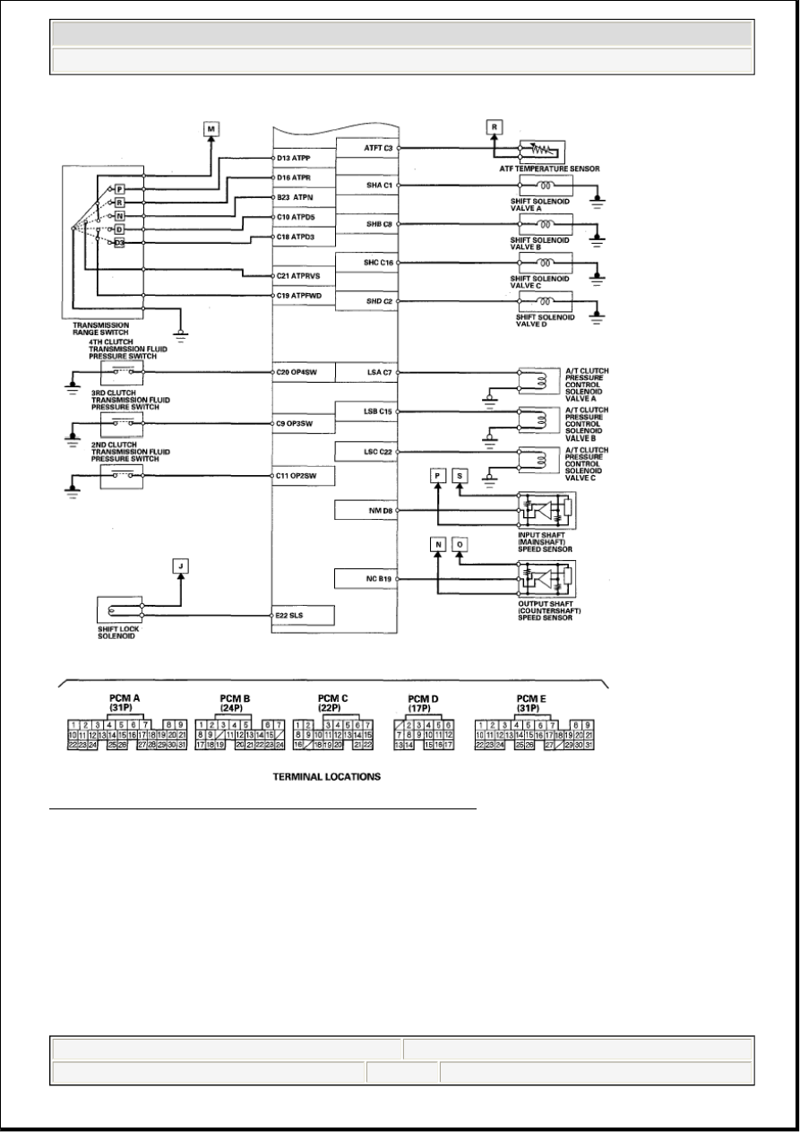
Fig. 15: PCM Electrical Connections Circuit Diagram (6 Of 6) 
Courtesy of AMERICAN HONDA MOTOR CO., INC. 

VACUUM HOSE ROUTING 


2007 Acura RL 

2005-08 ENGINE PERFORMANCE Fuel and Emissions Systems - RL


me 


Friday, June 05, 2009 2:33:27 PM

Page 31 

© 2005 Mitchell Repair Information Company, LLC. 

Fig. 16: Identifying Vacuum Hose Routing Components Location 
Courtesy of AMERICAN HONDA MOTOR CO., INC. 

VACUUM DISTRIBUTION 


2007 Acura RL 

2005-08 ENGINE PERFORMANCE Fuel and Emissions Systems - RL


me 


Friday, June 05, 2009 2:33:27 PM

Page 32 

© 2005 Mitchell Repair Information Company, LLC. 

Fig. 17: Vacuum Distribution Diagram 
Courtesy of AMERICAN HONDA MOTOR CO., INC. 

PCM INPUTS AND OUTPUTS AT CONNECTOR A (31P) 

Fig. 18: Identifying PCM Inputs And Outputs Connector Terminals A (31P) 
Courtesy of AMERICAN HONDA MOTOR CO., INC. 


2007 Acura RL 

2005-08 ENGINE PERFORMANCE Fuel and Emissions Systems - RL


me 


Friday, June 05, 2009 2:33:27 PM

Page 33 

© 2005 Mitchell Repair Information Company, LLC. 

CONNECTOR TERMINAL DESCRIPTION CHART 

NOTE:

Standard battery voltage is about 12 V.

Terminal number

Wire color

Terminal name

Description

Signal

1

BLK

PG2 (POWER 
GROUND)

Ground circuit for 
PCM circuit

Less than 1.0 Vat 
all times

2

BLK

PG1 (POWER 
GROUND)

Ground circuit for 
PCM circuit

Less than 1.0 V at 
all times

3

BRN/YEL

LG1 (LOGIC 
GROUND)

Ground circuit for 
PCM circuit

Less than 1.0 V at 
all times

4

YEL/BLK

IGP (POWER 
SOURCE)

Power source for 
PCM circuit

With ignition 
switch ON (II): 
battery voltage 
With ignition 
switch OFF: about 
0 V

5

RED/YEL

IAT (INTAKE AIR 
TEMPERATURE 
(IAT) SENSOR)

Detects IAT sensor 
signal

With ignition 
switch ON (II): 
about 0.1-4.8 V 
(depending on 
intake air 
temperature)

6

GRN/WHT

AFSHTCB2 (AIR 
FUEL RATIO (A/F) 
SENSOR HEATER 
CONTROL BANK 
2)

Drives front A/F 
sensor heater (Bank 
2, sensor 1)

With ignition 
switch ON (II): 
battery voltage 
With fully warmed 
up engine running: 
about 0 V or pulses

7

BLK/WHT

AFSHTCB1 (AIR 
FUEL RATIO (A/F) 
SENSOR HEATER 
CONTROL 
BANK1)

Drives rear A/F 
sensor heater (Bank 
1, sensor 1)

With ignition 
switch ON (II): 
battery voltage 
With fully warmed 
up engine running: 
about 0 V or pulses

8

GRN/RED

SO2SHTCB2 
(SECONDARY 
HEATED OXYGEN 
SENSOR 
(SECONDARY 
HO2S) HEATER 
CONTROL BANK 
2)

Drives front 
secondary HO2S 
heater (Bank 2, 
sensor 2)

With ignition 
switch ON (II): 
battery voltage 
With fully warmed 
up engine running: 
duty controlled

9

BLK/WHT

SO2SHTCB1 
(SECONDARY 
HEATED OXYGEN 
SENSOR 
(SECONDARY 
HO2S) HEATER 
CONTROL BANK 

Drives rear 
secondary HO2S 
heater (Bank 1, 
sensor 2)

With ignition 
switch ON (II): 
battery voltage 
With fully warmed 
up engine running: 
duty controlled


2007 Acura RL 

2005-08 ENGINE PERFORMANCE Fuel and Emissions Systems - RL


me 


Friday, June 05, 2009 2:33:27 PM

Page 34 

© 2005 Mitchell Repair Information Company, LLC. 


Content   ..  507  508  509  510   ..