Acura RL. Manual - part 149
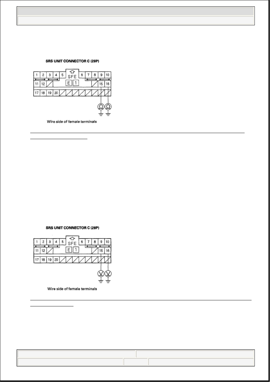
and between the No. 16 terminal and body ground. There should be an open circuit or at least 1
Mohms.
Fig. 243: Measuring Resistance Between No. 15 [No. 16] Terminal Of SRS Unit Connector C
(28P) And Body Ground
Courtesy of AMERICAN HONDA MOTOR CO., INC.
Is the resistance as specified?
YES - Go to step 9.
NO - Short to ground in the right side wire harness; replace the right side wire harness.
9. Reconnect the negative cable to the battery.
10. Turn the ignition switch ON (II).
11. Measure the voltage between the No. 15 terminal of SRS unit connector C (28P) and body ground,
and between the No. 16 terminal and body ground. There should be 1 V or less.
Fig. 244: Measuring Voltage Between No. 15 [No. 16] Terminal Of SRS Unit Connector C (28P)
And Body Ground
Courtesy of AMERICAN HONDA MOTOR CO., INC.
Is the voltage as specified?
YES - Go to step 12.
NO - Short to power in the right side wire harness; replace the right side wire harness.
2007 Acura RL
2005-08 RESTRAINTS SRS (Supplemental Restraint System) - RL
me
Friday, June 05, 2009 2:21:57 PM
Page 180 © 2005 Mitchell Repair Information Company, LLC.