Acura RL. Manual - part 132


  Index      Acura     Acura RL - service repair manual 2005-2008 year


Search            


Content   ..  130  131  132  133   ..


Acura RL. Manual - part 132


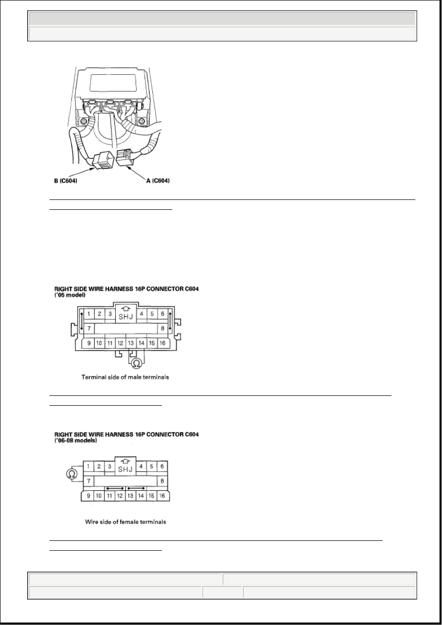
Fig. 137: Identifying Right Side Wire Harness 16P Connector C604 And Left Side Wire Harness 
Connector C604 - '06-08 Models
 
Courtesy of AMERICAN HONDA MOTOR CO., INC. 

14. Measure the resistance between the No. 13 [No. 1] and No. 14 [No. 7] terminals of the right side wire 

harness 16P connector C604. There should be 1.0 ohms or less. 

[ ] : '06-08 models 

Fig. 138: Measuring Resistance Between No. 13 And No. 14 Terminals Of Right Side Wire 
Harness 16P Connector C604
 
Courtesy of AMERICAN HONDA MOTOR CO., INC. 

Fig. 139: Measuring Resistance Between No. 1 And No. 7 Terminals Of Right Side Wire 
Harness 16P Connector C604
 
Courtesy of AMERICAN HONDA MOTOR CO., INC.


2007 Acura RL 

2005-08 RESTRAINTS SRS (Supplemental Restraint System) - RL


me 


Friday, June 05, 2009 2:21:56 PM

Page 112  © 2005 Mitchell Repair Information Company, LLC. 

Is the resistance as specified?  

YES - Open or increased resistance in the left side wire harness; replace left side wire harness. 

NO - Open or increased resistance in the right side wire harness; replace the right side wire harness. 

DTC 31-3X ("X" CAN BE 0 THRU 9 OR A THRU F): SHORT TO ANOTHER WIRE OR 
DECREASED RESISTANCE IN DRIVER'S SIDE AIRBAG INFLATOR 

Special Tools Required  

SRS inflator simulator 07SAZ-TB4011A  

SRS simulator lead E 07XAZ-S1A0200  

SRS short canceller 070AZ-SAA0100  

1. Clear the DTC memory (see CLEAR THE DTC MEMORY WITH THE HDS ).  

2. Turn the ignition switch ON (II), and check that the SRS indicator comes on for about 6 seconds and 

then goes off. 

Does the SRS indicator stay on, and is DTC 31-3x indicated?  

YES - Go to step 3. 

NO - Intermittent failure, the system is OK at this time. Go to TROUBLESHOOTING 
INTERMITTENT FAILURES
 . If another DTC is indicated, troubleshoot the DTC. 

3. Turn the ignition switch OFF. Disconnect the negative cable from the battery, then wait for 3 minutes. 

4. Disconnect the left side wire harness 2P connector (A) from the driver's side airbag (B). 

Fig. 140: Identifying Left Side Wire Harness 2P Connector And Driver's Side Airbag

NOTE:

Before doing this troubleshooting procedure, review SRS Precautions and 
Procedures (see PRECAUTIONS AND PROCEDURES ) and General 
Troubleshooting Information (see GENERAL TROUBLESHOOTING 
INFORMATION ).


2007 Acura RL 

2005-08 RESTRAINTS SRS (Supplemental Restraint System) - RL


me 


Friday, June 05, 2009 2:21:56 PM

Page 113  © 2005 Mitchell Repair Information Company, LLC. 

Courtesy of AMERICAN HONDA MOTOR CO., INC.

5. Connect the SRS inflator simulator (2 ohms connectors) and simulator lead E to the left side wire 

harness.  

6. Reconnect the negative cable to the battery.  

7. Clear the DTC memory.  

8. Read the DTC (see GENERAL TROUBLESHOOTING INFORMATION ). 

Is DTC 31-3x indicated?  

YES - Go to step 9. 

NO - Short to another wire in the driver's side airbag inflator; replace the driver's side airbag (see 
SIDE AIRBAG REPLACEMENT ). 

9. Turn the ignition switch OFF. Disconnect the negative cable from the battery, then wait for 3 minutes. 

10. Disconnect SRS unit connector C (28P) from the SRS unit (see step 7 ).  

11. Disconnect the SRS inflator simulator from the SRS simulator lead.  

12. Connect the SRS short canceller (070AZ-SAA0100) to the No. 1 and No. 2 terminals of SRS unit 

connector C (28P) (see OPENING THE SRS UNIT SHORTING CONNECTORS FOR 
DIAGNOSIS
 ).  

13. Measure the resistance between the terminals of the SRS simulator lead. There should be an open 

circuit or at least 1M ohms. 

Fig. 141: Measuring Resistance Between Terminals Of SRS Simulator Lead 
Courtesy of AMERICAN HONDA MOTOR CO., INC. 

Is the resistance as specified?  

YES - Faulty SRS unit or poor connection at SRS unit connector C (28P) and the SRS unit. Check the 
connection; if the connection is OK, replace the SRS unit (see SRS UNIT REPLACEMENT ). 

NO - Go to step 14. 

14. Disconnect right side wire harness 16P connector C604 (A) from the left side wire harness connector 


2007 Acura RL 

2005-08 RESTRAINTS SRS (Supplemental Restraint System) - RL


me 


Friday, June 05, 2009 2:21:56 PM

Page 114  © 2005 Mitchell Repair Information Company, LLC. 

C604 (B). 

'05 model  

Fig. 142: Identifying Right Side Wire Harness 16P Connector C604 And Left Side Wire Harness 
Connector C604 - '05 Model
 
Courtesy of AMERICAN HONDA MOTOR CO., INC. 

'06-08 models  

Fig. 143: Identifying Right Side Wire Harness 16P Connector C604 And Left Side Wire Harness 
Connector C604 - '06-08 Models
 
Courtesy of AMERICAN HONDA MOTOR CO., INC. 

15. Measure the resistance between the No. 13 [No. 1] terminal of the right side wire harness 16P 

connector C604 and body ground, and between the No. 14 [No. 7] terminal and body ground. There 
should be an open circuit or at least 1Mohms. 

[ ] : '06-08 models 


2007 Acura RL 

2005-08 RESTRAINTS SRS (Supplemental Restraint System) - RL


me 


Friday, June 05, 2009 2:21:56 PM

Page 115  © 2005 Mitchell Repair Information Company, LLC. 


Content   ..  130  131  132  133   ..