Acura CSX. Manual - part 704
03
04
05
01
−
−
−
−
−
−
YES
NO
YES
NO
YES
NO
24-133
LEFT SIDE IMPACT SENSOR
(SECOND) 2P CONNECTOR
LEFT SIDE IMPACT SENSOR
(SECOND) 2P CONNECTOR
LEFT SIDE IMPACT SENSOR
(SECOND) 2P CONNECTOR
B
070AZ-SNAA300
07SAZ-TB4011A
A
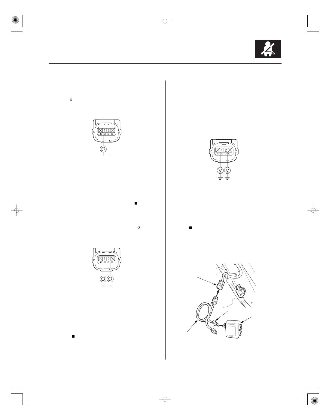
10. Measure the resistance between left side impact
sensor (second) 2P connector terminals No. 1 and
No. 2. There should be an open circuit or at least
1 M
.
Go to step 11.
Short in the floor wire harness; replace the
floor wire harness, then clear the DTC.
11. Measure the resistance between body ground and
left side impact sensor (second) 2P connector
terminals No. 1 and No. 2, individually. There
should be an open circuit or at least 1 M
.
Go to step 12.
Short to ground in the floor wire harness;
replace the floor wire harness, then clear the
DTC.
12. Reconnect the negative cable to the battery.
13. Turn the ignition switch to ON (II).
14. Measure the voltage between body ground and left
side impact sensor (second) 2P connector terminals
No. 1 and No. 2, individually. There should be less
than 0.2 V.
Go to step 15.
Short to power in the floor wire harness;
replace the floor wire harness, then clear the
DTC.
15. Turn the ignition switch to LOCK (0).
16. Connect the SRS inflator simulator (jumper
connector) and the red lead (A) of simulator lead L
to the floor wire harness 4P connector (B).
Terminal side of female terminals
Terminal side of female terminals
Terminal side of female terminals
Is the r esistance as specif ied?
Is the r esistance as specif ied?
Is the voltage as specif ied?
08/08/21 13:59:43 61SNR030_240_0133