Acura CSX. Manual - part 686
01
SNR9A00K791000R129XFAAT00
−
−
−
−
DTC 12-9x (‘‘x’’ can be 0 thru 9 or A thru F):
DTC 12-Bx (‘‘x’’ can be 0 thru 9 or A thru F):
Special Tools Required
YES
NO
YES
NO
24-61
A
070AZ-SNAA100
07SAZ-TB4011A
Short to Ground in the Front Passenger’s
Airbag First Inflator
Short to Ground in the Front Passenger’s
Airbag Second Inflator
• SRS inflator simulator 07SAZ-TB4011A
• SRS simulator lead J 070AZ-SNAA100
NOTE: Before doing this troubleshooting procedure,
review SRS Precautions and Procedures (see page
24-13), General Troubleshooting Information (see page
24-22), and Battery Terminal Disconnection and
Reconnection (see page 22-68).
1. Clear the DTC memory (see page 24-23).
2. Turn the ignition switch to ON (II), and check that
the SRS indicator comes on for about 6 seconds
and then goes off.
Go to step 3.
Intermittent failure, system is OK at this time.
Go to Troubleshooting Intermittent Failures
(see page 24-24). If another DTC is indicated,
troubleshoot the DTC.
3. Turn the ignition switch to LOCK (0). Disconnect the
negative cable from the battery, then wait at least 3
minutes.
4. Remove the lower glove box (see page 20-104),
then disconnect the front passenger’s airbag 4P
connector (A) from the dashboard wire harness.
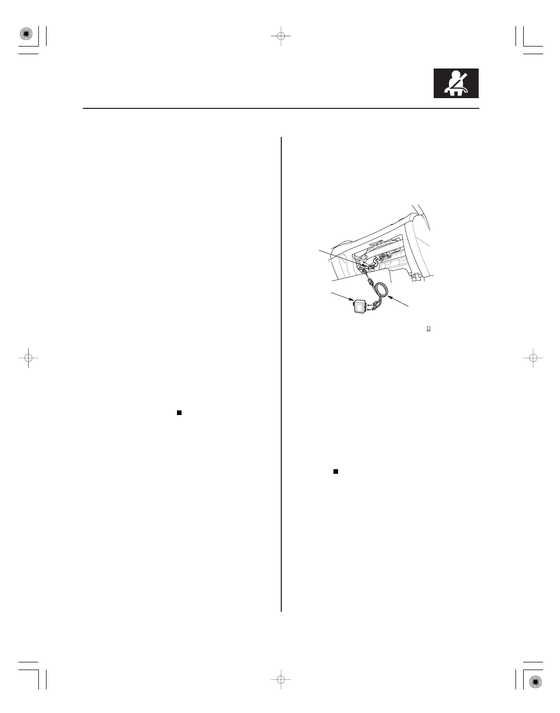
5. Connect the SRS inflator simulator (2
connectors) and simulator lead J to the dashboard
wire harness.
6. Reconnect the negative cable to the battery.
7. Clear the DTC memory.
8. Read the DTC (see page 24-22).
Go to step 9.
Short to ground in the front passenger’s
airbag first or second inflator; replace the front
passenger’s airbag (see page 24-189), then clear
the DTC.
9. Turn the ignition switch to LOCK (0). Disconnect the
negative cable from the battery, then wait at least 3
minutes.
10. Disconnect SRS unit connector A (28P) from the
SRS unit (see step 9 on page 24-21).
11. Disconnect the SRS inflator simulator from the SRS
simulator lead. Do not disconnect the simulator
lead from the dashboard wire harness 4P connector.
Does the SRS indicator stay on, and is DT C 12-9x
or 12-Bx indicated?
Is DT C 12-9x or 12-Bx indicated?
08/08/21 13:56:54 61SNR030_240_0061