Acura CSX. Manual - part 650
*33
*34
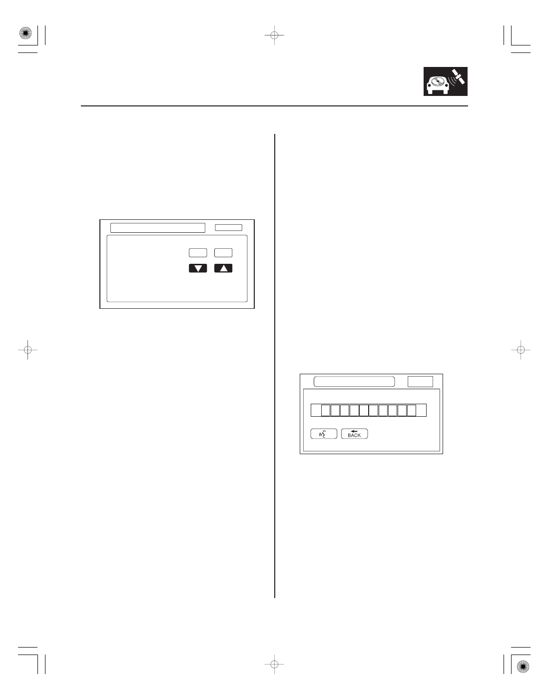
Demo Mode
Mic Level
23-311
Return
Demo Mode
OFF
Demo
Speed Rate
150 ms
ON
OFF
Mic Level
Return
Mic Level
Steering Switch
This screen is for factory use only, and should always
be set to OFF. Occasionally the DEMO setting is turned
ON when vehicles are being used at Auto Shows or
similar events. Turning this feature on, allows the
navigation system to automatically follow a route to a
destination when the vehicle is stationary. The Speed
changes the speed of the demo mode.
This diagnostic allows you to independently test the
microphone and the navigation TALK and BACK
buttons. They are used to activate the voice control
system. The microphone is located near the map light
in the roof console. It is directional, and works only with
the voice coming from the driver’s seat.
• Press the navigation TALK button on the steering
wheel, wait unit you hear a beep, and in a normal
voice say ‘‘testing’’. The TALK indicator on the screen
should momentarily turn green, and the text Now
Recording... should appear in yellow. If the talk
indicator shown on the screen does not briefly turn
green, check the wiring from the steering wheel
navigation TALK button to the navigation unit. If there
is no Mic Level movement when you speak, then you
should check the wires running from the microphone
in the roof console to the HandsFreeLink control unit
and the navigation unit. If the wires are OK, the
microphone must be faulty; replace the microphone
located in roof console (see page 23-358).
• Press the navigation BACK button on the steering
wheel. This should cause the Cancel indicator on the
screen to momentarily turn green. If it does not
briefly turn green, check the wiring from the steering
wheel navigation BACK button to the navigation unit.
08/08/21 14:16:43 61SNR030_230_0314