Acura CSX. Manual - part 606


  Index      Acura     Acura CSX - P/NO. 61SNR03 - service repair manual 2006-2009 year


Search            


Content   ..  604  605  606  607   ..


Acura CSX. Manual - part 606


*21

*22

*23

*24

Black Raster

Color Pattern

Monitor Adjustment

Touch Panel Check

23-138

Navigation System

Black Raster

Color Pattern

Return

Return

Red

Green

Blue

Monitor Adjuntment

Return

Tuning

Default

( 0, 0 )

Default

( 0, 0 )

Setting

H-POS

Return

X:0 Y:0

X:227 Y:111

X:479 Y:233

The entire display must be black. This diagnostic screen
checks for pixels that may be stuck (on). If pixels are
stuck on, replace the navigation unit.

The chart below shows the colors being used for the
various screens. This is for factory use only. To check
the color signal use the RGB test.

It is unlikely that you will ever need to adjust the
monitor position. This is for factory use only. The
Default button will reset the display position to factory
specifications. The factory default is 0, 0. The H-POS
button is for factory use only.

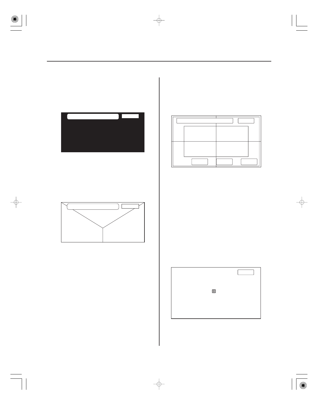
The panel touch sensing system consists of a touch
sensitive resistive membrane covering the display.
Contrary to other systems using infrared beams, the
screen has to be physically touched to make it work.
The display has the capability of 479 touch locations
(left to right), and 233 touch locations (top to bottom).
The upper left hand corner is position (0, 0) and the
lower right hand corner is (479, 233) as displayed.
Touching anywhere on the screen displays the
coordinate of the location, and a

icon appears where

you touched the screen. If any area of the screen either
doesn’t respond, or responds at some other location
when touched, then replace the navigation unit.

NOTE: Unlike earlier screens that used infrared sensors,
direct sunlight will not affect this test.

08/08/21 14:07:30 61SNR030_230_0141

*25

*26

Touch Panel Calibration

Unit Check

23-139

Return

Set

1

2

3

4

5

Please press the center of’’

’’button.

Select Check Units

Return

Display

Radio

Navi ECU

PC Card Info.

Hard Key

The display screen uses a touch sensitive membrane.
This means that every location of the entire surface of
the display is touch sensitive. This diagnostic allows
alignment of these touch locations with the location of
the buttons images on the screen.

Normally this should never need adjustment, and is
used only to adjust the touch locations for parallax (the
touch locations appear different when viewed at an
angle). However, if an adjustment is necessary, follow
this procedure:

• The screen consists of the

button icons. Touch the

center of the five

buttons on order 1

5.

• To store any change you make, touch the Set button.
• Use the Return key to exit the diagnostic.

Select the item you want to check, and the test starts.

• Display
• Radio
• Navi ECU
• PC Card Info
• Hard Key

08/08/21 14:07:30 61SNR030_230_0142

*27

*28

*29


Display

Radio

Navi ECU

23-140

Navigation System

Display

OK

OK

Connection

Version

040423

Radio

OK

Connection

OK

0 mV

AM Electric Field Intensity

0 mV

FM Electric Field Intensity

7150

CD Mech. Version

Navi ECU

OK

V

RAM

OK

OK

D

RAM

OK

GPS
DVD

ROM

Serial NO.

ABC01234567

Mem Clear

-

Return

Return

Return

This performs additional checks on the communication
bus between navigation CPU and the display. In
addition, the test checks the internal electronic
functions.

If the connection is NG, replace the navigation unit.

• Connection verifies internal communications.
• Version represents the software version for the

display.

This diagnostic screen checks the internals of the radio
(AM and FM) and CD player. If NG, replace the
navigation unit.

This screen looks for problems with the navigation unit.
When you initiate this diagnostic, the navigation unit
may freeze of delay up to a minute while the diagnostic
runs.

• If V-RAM or D-RAM is NG, then replace the navigation

unit.

• If GPS indicates NG (ANT), check the entire GPS

antenna wire from the navigation unit to the antenna.
If the wire is crushed or damaged, try a known-good
antenna. If this diagnostic reads OK, then order a new
GPS antenna. If the diagnostic still reads NG (ANT),
replace the navigation unit.

• DVD ROM represents the database version on the

DVD. You can also find this information in setup by
selecting System Information.

• Serial No. should be the same as the serial number

found on the underside of the navigation unit. You
need this number to obtain the security code from the
Interactive Network system.

• Mem Clear is for factory use, and should never be

used unless instructed by the factory. Accidental
selection will erase the client’s personal data, PINS,
and settings. If selected, a popup box appears asking
if you want to clear the memory. If so, select Yes.

08/08/21 14:07:31 61SNR030_230_0143

+ −

+ −

*30

*31

*32

*33

PC Card info

Hard Key

Car Status

23-141

PC Card Information

Return

Return

PC Card is not inserted.

PC Card Information

Return

Manufacturer

xxxxxx

Product Name

xxxxxx

FILES

Hard Key

Return

ZOOM OUT

ZOOM IN

CANCEL

SET UP

MAP

MENU

INFO

MODE

CH

CH

VOL

VOL

FF

REW

RPT

RDM

SEEK UP

SCAN

AUDIO

CD/AUX

AM/FM

SKIP

SKIP

SEEK DOWN

Keep Pushing to Return.

Car Status

0

VSP

0

ILL

0

BACK

Close

Display

0

ILL CANCEL

There is no PC card in the PC slot, and the screen
should display, PC card is not inserted.

If the factory provides a PC card and instructs you to
insert it, the screen displays the Manufacturer, and
Product Name as shown in the following screen. Touch
the FILES button to see the contents of the card.

This diagnostic screen checks the status of each of the
hard buttons surrounding the navigation display. When
you press each hard button, the corresponding item on
the screen should flash blue. Touch the return key, or
press and hold the joystick to exit.

NOTE: It is normal for the VOL (

,

) CH (

,

) and

MODE button to be inactive.

Use this screen to confirm that navigation unit is
properly receiving input signals. Signals equal to (0) are
OFF, and signals equal to (1) are ON. If the value on the
display does not match the actual vehicle status, then
check the wire carrying the signal.

• VSP-Vehicle Speed Pulse from ECM/PCM connector A

(Navigation unit connector A (17P) terminal No. 13)
a) OFF (0) when vehicle is not moving
b) ON (1) when vehicle is moving

The VSP comes from the ECM/PCM as a dedicated
signal. Internally, the navigation unit compares the
actual VP on the map against street data to adjust the
pulse to speed scaling factor.

• BACK-Reverse indication from taillight relay

(Navigation unit connector C (12P) terminal No. 7)
a) OFF (0) when shift lever is in any position other
than reverse
b) ON (1) when shift lever is in reverse

The Back signal is used by the navigation unit to allow
the map screen to show the VP moving backwards
when in reverse and to trigger the optional rear view
camera. This signal is needed because the Speed Pulse
does not provide any directional information to the
system.

• ILL CANCEL

a) OFF (0) when the dash lights brightness control
button is less than 90 % brightness with the
headlights turned on.
b) ON (1) when the dash lights brightness control
button is more than 90 % brightness with the
headlights turned on.

08/08/21 14:07:31 61SNR030_230_0144


Content   ..  604  605  606  607   ..