Acura CSX. Manual - part 587
*16
SNR9ANJJ10300000000FAAT26
−
+
−
−
−
−
−
−
Audio remote switch does not work properly
(without navigation)
YES
NO
YES
NO
AUDIO REMOTE SWITCH TABLE
YES
NO
23-65
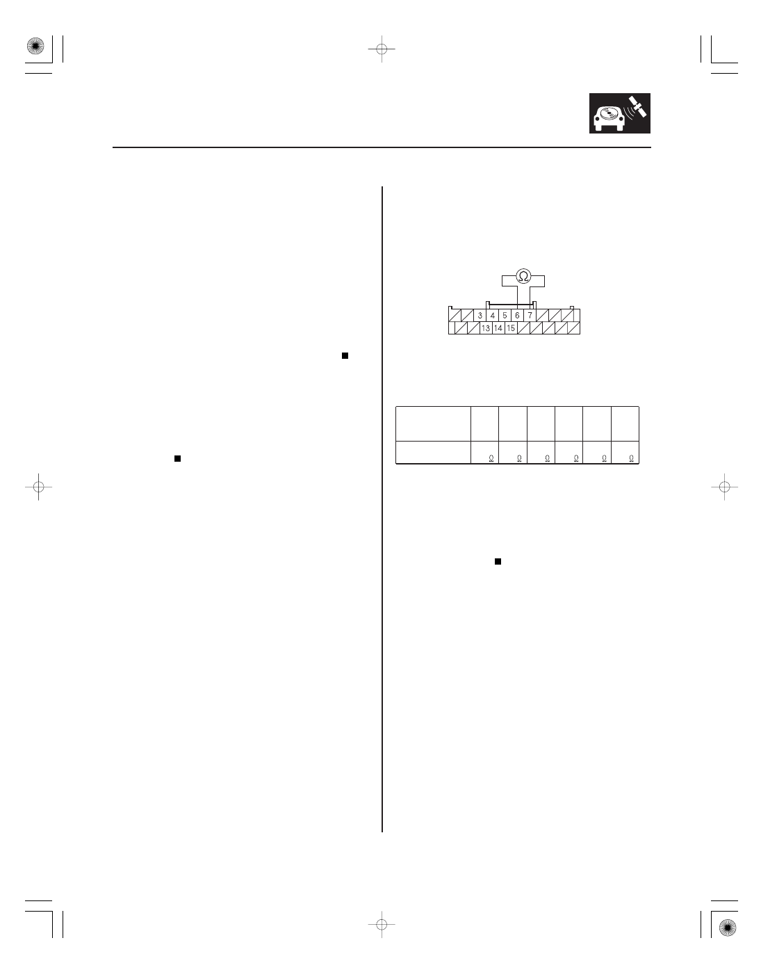
AUDIO UNIT CONNECTOR B (20P)
REMOTE GND (BRN)
AUDIO REMOTE SW (PNK)
NOTE:
• Check the vehicle battery condition first.
• Check the connectors for poor connections or loose
terminals.
1. Check the audio unit operation.
Go to step 2.
Replace the audio unit (see page 23-80).
2. Test the audio remote switch (see page 23-86).
Go to step 3.
Replace the audio remote switch (see page
23-86).
3. Remove the audio unit (see page 23-80).
4. Measure the resistance between audio unit
connector B (20P) terminals No. 6 and No. 7 as
specified in the table.
Go to step 5.
Repair open or high resistance in the circuit
between the audio unit and the audio remote
switch. If the wires are OK, replace the cable reel
(see page 24-200).
Button held down
VOL
DOWN
VOL UP CH ( ) CH ( ) MODE
No
button
pressed
Resistance
about
100
about
357
about
775
about
1.7 k
about
3.7 k
about
10 k
Wire side of female terminals
Is the audio unit oper ation OK ?
Is the audio r emote switch OK ?
Is the r esistance OK ?
08/08/21 14:05:32 61SNR030_230_0068