Acura CSX. Manual - part 490
05
01
SNR9A00G24113614601KBAT80
21-77
21-77
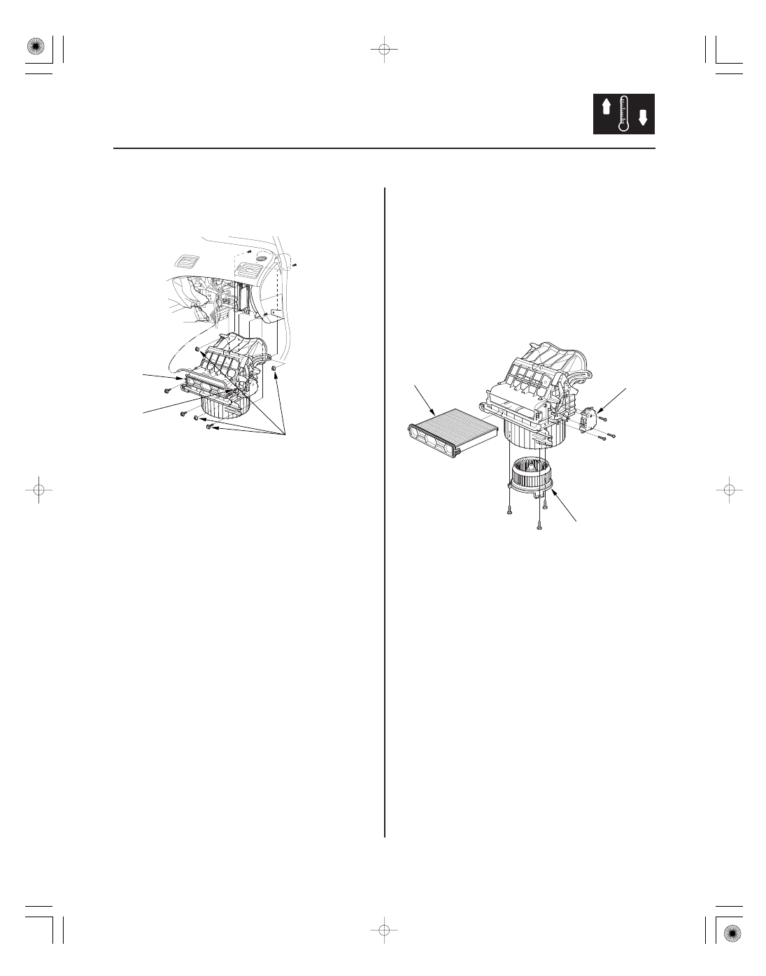
Blower Unit Component
Replacement
6 x 1.0 mm
9.8 N·m
(1.0 kgf·m, 7.2 lbf·ft)
B
A
C
B
A
6. Disconnect the connector (A) from the recirculation
control motor. Remove the self-tapping screws, the
bolt, the mounting nuts, and the blower unit (B).
7. Install the unit in the reverse order of removal.
Make sure that there is no air leakage.
Note these items when overhauling the blower unit:
• The recirculation control motor (A), blower motor (B),
and the dust and pollen filter (C) can be replaced
without removing the blower unit.
• Before reassembly, make sure that the recirculation
control linkage and door move smoothly without
binding.
• After reassembly, make sure the recirculation control
motor runs smoothly (see page 21-74).
08/08/21 14:43:40 61SNR030_210_0078