Acura CSX. Manual - part 416


  Index      Acura     Acura CSX - P/NO. 61SNR03 - service repair manual 2006-2009 year


Search            


Content   ..  414  415  416  417   ..


Acura CSX. Manual - part 416


01

SNR9AC7D52100068011KBAT00

01

SNR9AC7D52100000000BBAT01

19-169

19-169

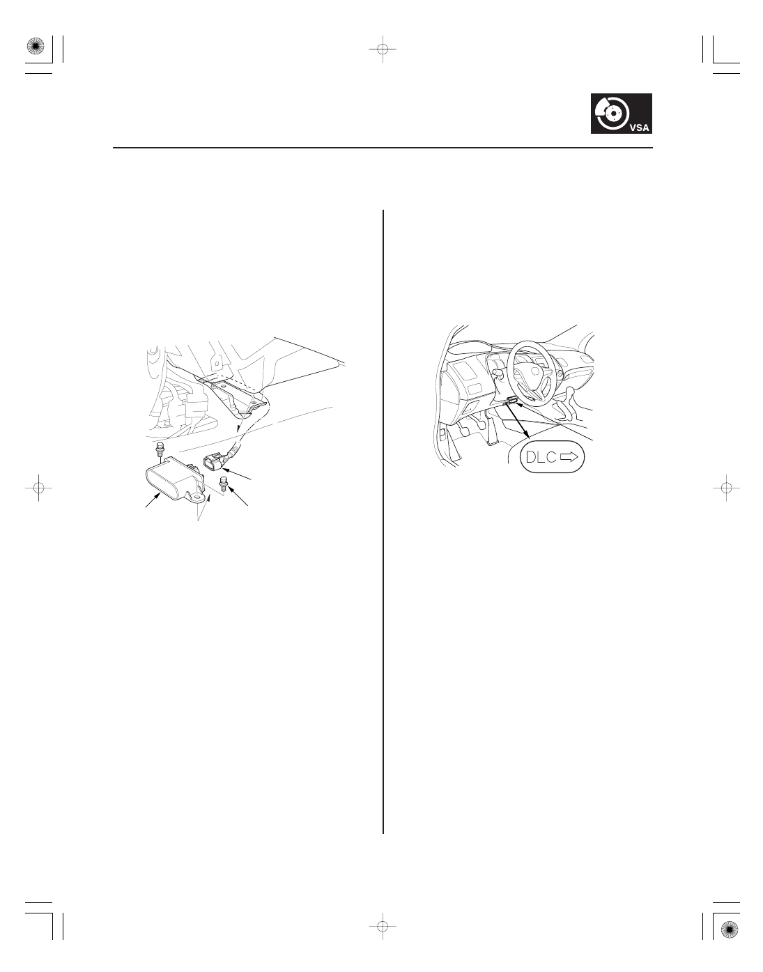
Yaw Rate-Lateral Acceleration
Sensor Replacement

VSA Sensor Neutral Position
Memorization

A

B

9.8 N·m
(1.0 kgf·m, 7.2 lbf·ft)

A

NOTE:

• Do not damage or drop the sensor as it is sensitive.
• Do not use power tools when replacing the sensor.

1. Turn the ignition switch to LOCK (0).

2. Remove the center console (see page 20-92).

3. Remove the yaw rate-lateral acceleration sensor

(A) mounting bolts.

4. Pull out the yaw rate-lateral acceleration sensor,

then disconnect the sensor connector (B).

5. Install the yaw rate-lateral acceleration sensor in

the reverse order of removal.

6. Do the VSA sensor neutral position memorization

(see page 19-169).

NOTE: Do not press the brake pedal during this
procedure.

1. Park the vehicle on a flat and level surface, with the

steering wheel in the straight ahead position.

2. With the ignition switch in LOCK (0), connect the

HDS to the data link connector (DLC) (A) under the
driver’s side of the dashboard.

3. Turn the ignition switch to ON (II).

4. Make sure the HDS communicates with the vehicle

and the VSA modulator-control unit. If it doesn’t
troubleshoot the DLC circuit (see page 11-204).

5. Select VSA ADJUSTMENT with the HDS, and

follow the screen prompts.

NOTE: See the HDS Help menu for specific
instructions.

6. Turn the ignition switch to LOCK (0).

08/08/21 15:06:46 61SNR030_190_0169

01

02

03

SNR9AC7D52100063651FEAT00

19-170

VSA System Components

VSA OFF Switch Test

A

B

VSA OFF SWITCH 5P CONNECTOR

GND

VSA OFF SW

VSA OFF SWITCH 5P CONNECTOR

ILL (

)

ILL (

)

1. Turn the ignition switch to LOCK (0).

2. Remove the driver’s dashboard lower cover

(see page 20-102).

3. Push out the VSA OFF switch (A) from the back of

the instrument panel.

4. Disconnect the VSA OFF switch 5P connector (B).

5. Check for continuity between the VSA OFF switch

5P connector terminals No. 1 and No. 2 . There
should be continuity when the button is pressed,
and no continuity when the button is released.

6. Check for continuity between VSA OFF switch 5P

connector terminals No. 4 and No. 5. There should
be continuity at all times.

7. Install the VSA OFF switch in the reverse order of

removal.

Terminal side of male terminals

Terminal side of male terminals

08/08/21 15:06:46 61SNR030_190_0170

01

SNR9AC7D52100063635KDAT00

Removal

19-171

VSA Modulator-Control Unit Removal and Installation

A

C

B

I

E

F

G

H

J

9.8 N·m (1.0 kgf·m, 7.2 lbf·ft)

9.8 N·m (1.0 kgf·m, 7.2 lbf·ft)

15 N·m (1.5 kgf·m, 11 lbf·ft)

D
22 N·m
(2.2 kgf·m, 16 lbf·ft)

NOTE:

• Do not spill brake fluid on the vehicle; it may damage the paint; if brake fluid gets on the paint, wash it off

immediately with water.

• Be careful not to damage or deform the brake lines during removal and installation.
• Plug the ends of the hoses and the joints to prevent spilling brake fluid.

1. Turn the ignition switch to LOCK (0).

2. Disconnect the VSA modulator-control unit 37P connector (A) by pushing the lock (B) and pulling down the lever

(C); the connector disconnects itself.

3. Disconnect the six brake lines from the VSA modulator-control unit.

NOTE: Brake lines are connected to the master cylinder (D) and to the right-front (E), the left-rear (F), the right-rear
(G), and the left-front (H) brake systems.

4. Remove the VSA modulator-control unit (I) with the bracket (J) from the body.

5. Remove the VSA modulator-control unit from the bracket.

08/08/21 15:06:47 61SNR030_190_0171

Installation

19-172

VSA System Components

1. Install the VSA modulator-control unit onto the bracket.

2. Install the bracket with the VSA modulator-control unit to the body.

3. Reconnect the six brake lines, then tighten the flare nuts to the specified torque.

4. Align the connecting surface of the VSA modulator-control unit 37P connector to the VSA modulator-control unit.

5. Pull up the lever of the VSA modulator-control unit 37P connector, then confirm the connector is fully seated.

6. Bleed the brake system (see page 19-9).

7. Do the VSA sensor neutral position memorization (see page 19-169).

8. Start the engine, and make sure the ABS and the VSA indicators go off.

9. Test-drive the vehicle, and make sure the ABS, and the VSA indicators do not come on.

NOTE: If the brake pedal is spongy, there may be air trapped in the modulator which could then be induced into
the normal brake system during modulation. Bleed the brake system again (see page 19-9).

08/08/21 15:06:47 61SNR030_190_0172


Content   ..  414  415  416  417   ..