Acura CSX. Manual - part 393
01
SNR9AC6K701000R5112FAAT00
+
−
−
−
−
−
−
DTC 51-12:
YES
NO
YES
NO
YES
NO
19-76
ABS Components
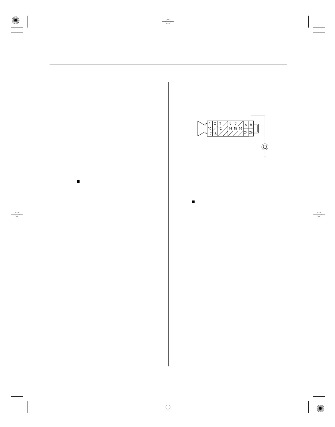
ABS MODULATOR-CONTROL UNIT 25P CONNECTOR
MR
B (RED)
Motor Drive Circuit Malfunction
1. Turn the ignition switch to ON (II).
2. Clear the DTC with the HDS.
3. Turn the ignition switch to LOCK (0), then turn it to
ON (II) again.
4. Check for DTCs with the HDS.
Go to step 5.
Intermittent failure, the system is OK at this
time. Check for loose terminals at the ABS
modulator-control unit 25P connector. Refer to
intermittent failures troubleshooting (see page
19-50).
5. Turn the ignition switch to LOCK (0).
6. Check the No. 3 (30 A) fuse in the under-hood fuse/
relay box.
Go to step 7.
Reinstall the checked fuse, then go to step 14.
7. Disconnect the ABS modulator-control unit 25P
connector (see step 2 on page 19-90).
8. Check for continuity between ABS modulator-
control unit 25P connector terminal No. 9 and body
ground.
Repair short to body ground in the wire
between the No. 3 (30 A) fuse in the under-hood
fuse/relay box and the ABS modulator-control
unit.
Install a new No. 3 (30 A) fuse in the under-
hood fuse/relay box, then go to step 9.
Wire side of female terminals
Is DT C 51-12 indicated?
Is the f use blown?
Is ther e continuity?
08/08/21 15:03:15 61SNR030_190_0076