Acura CSX. Manual - part 307


  Index      Acura     Acura CSX - P/NO. 61SNR03 - service repair manual 2006-2009 year


Search            


Content   ..  305  306  307  308   ..


Acura CSX. Manual - part 307


01

SNR9AA1E10480139301MEAT00

SPRING SPECIFICATIONS

Springs

Standard (New)-Unit: mm (in.)

Wire Diameter

O.D.

Free Length

No. of Coils

14-303

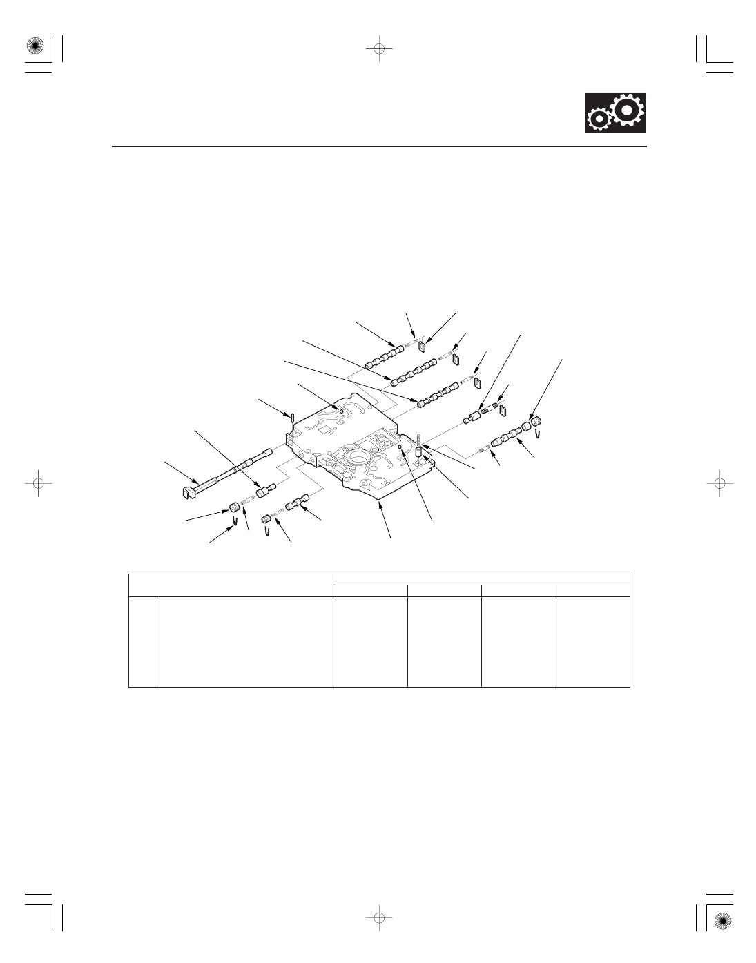
Main Valve Body Disassembly, Inspection, and Reassembly

A

SPRING SEAT

B

C

RELIEF VALVE

D

VALVE SLEEVE

MAIN VALVE BODY

CHECK BALL

COOLER CHECK
VALVE

F

E

LOCK-UP
CONTROL
VALVE

SHIFT VALVE E

SHIFT VALVE A

SHIFT VALVE B

SHIFT VALVE C

CHECK BALL

ROLLER

SERVO CONTROL VALVE

MANUAL VALVE

VALVE CAP

VALVE CAP CLIP

G

H

1. Clean all parts thoroughly in solvent, and dry them with compressed air. Blow out all passages.

2. Do not use a magnet to remove the check balls, it may magnetize the balls.

3. Inspect the valve body for scoring and damage.

4. Check all valves for free movement. If any fail to slide freely, do the valve body repair procedure (see page 14-301).

5. Coat all parts with ATF during assembly.

A

Shift valve A spring

0.8 (0.031)

5.6 (0.220)

28.1 (1.106)

15.9

B

Shift valve B spring

0.8 (0.031)

5.6 (0.220)

28.1 (1.106)

15.9

C

Shift valve C spring

0.8 (0.031)

5.6 (0.220)

28.1 (1.106)

15.9

D

Relief valve spring

1.0 (0.039)

9.6 (0.378)

34.1 (1.343)

10.2

E

Lock-up control valve spring

0.65 (0.026)

7.1 (0.280)

23.1 (0.909)

12.7

F

Cooler check valve spring

0.85 (0.033)

6.6 (0.260)

27.0 (1.063)

11.3

G

Servo control valve spring

0.7 (0.028)

6.6 (0.260)

35.7 (1.406)

17.2

H

Shift valve E spring

0.8 (0.031)

5.6 (0.220)

28.1 (1.106)

15.9

08/08/21 14:51:13 61SNR030_140_0305

01

02

03

SNR9AA1E10480113021MAAT00

ATF Pump Gears Side (Radial) Clearance:
Standard (New):
ATF Pump Drive Gear:
0.210

0.265 mm (0.0083

0.0104 in.)

ATF Pump Driven Gear:
0.070

0.125 mm (0.0028

0.0049 in.)

ATF Pump Drive/Driven Gear Thrust (Axial)
Clearance:
Standard (New): 0.03

0.06 mm (0.001

0.002 in.)

Service Limit:

0.07 mm (0.003 in.)

14-304

Valve Body

ATF Pump Inspection

A

B

C

D

A

B

C

B

A

D

1. Install the ATF pump drive gear (A), the driven gear

(B), and the ATF pump driven gear shaft (C) in the
main valve body (D). Lubricate all parts with ATF,
and install the ATF pump driven gear with its
grooved and chamfered side facing up.

2. Measure the side clearance of the ATF pump drive

gear (A) and the driven gear (B).

3. Remove the ATF pump driven gear shaft. Measure

the thrust clearance between the ATF pump driven
gear (A) and the valve body (B) using a straight
edge (C) and a feeler gauge (D).

08/08/21 14:51:13 61SNR030_140_0306

*01

SNR9AA1E10480150701MEAT00

SPRING SPECIFICATIONS

Springs

Standard (New)-Unit: mm (in.)

Wire Diameter

O.D.

Free Length

No. of Coils

14-305

Regulator Valve Body Disassembly, Inspection, and Reassembly

6 x 1.0 mm
12 N·m (1.2 kgf·m, 8.7 lbf·ft)

F

G

H

1ST ACCUMULATOR
PISTON

O-RING

REGULATOR VALVE BODY

LOCK-UP SHIFT VALVE

E

VALVE CAP CLIP

VALVE CAP

REGULATOR VALVE

TORQUE CONVERTER
CHECK VALVE

D

SPRING SEAT

A

B

C

ACCUMULATOR COVER

3RD ACCUMULATOR PISTON

REGULATOR
SPRING CAP

STOP BOLT
6 x 1.0 mm
12 N·m (1.2 kgf·m,
8.7 lbf·ft)

BAFFLE PLATE

1. Clean all parts thoroughly in solvent, and dry them with compressed air. Blow out all passages.

2. Inspect the valve body for scoring and damage.

3. Check all valves for free movement. If any fail to slide freely, do the valve body repair procedure (see page 14-301).

4. Hold the regulator spring cap in place while removing the stop bolt. The regulator spring cap is spring loaded.

5. Coat all parts with ATF during assembly.

6. Replace the O-rings with new ones.

7. When reassembling the valve body, align the hole in the regulator spring cap with the hole in the valve body, then

press the spring cap into the valve body, and tighten the stop bolt.

A

Stator reaction spring

4.5 (0.177)

35.4 (1.394)

30.3 (1.193)

1.92

B

Regulator valve spring A

1.9 (0.075)

14.7 (0.579)

80.6 (3.173)

16.1

C

Regulator valve spring B

1.6 (0.063)

9.2 (0.362)

44.0 (1.732)

12.5

D

Torque converter check valve spring

1.2 (0.047)

8.6 (0.339)

33.8 (1.331)

12.2

E

Lock-up shift valve spring

1.0 (0.039)

6.6 (0.260)

35.5 (1.398)

18.2

F

3rd accumulator spring

2.5 (0.098)

14.6 (0.575)

29.9 (1.177)

4.9

G

1st accumulator spring A

2.4 (0.094)

18.6 (0.732)

49.0 (1.929)

7.1

H

1st accumulator spring B

2.3 (0.091)

12.2 (0.480)

31.5 (1.240)

6.6

Replace.

08/08/21 14:51:14 61SNR030_140_0307

01

SNR9AA1E10480154501MEAT00

SPRING SPECIFICATIONS

Springs

Standard (New)-Unit: mm (in.)

Wire Diameter

O.D.

Free Length

No. of Coils

14-306

Valve Body

Servo Body Disassembly, Inspection, and Reassembly

6 x 1.0 mm
12 N·m (1.2 kgf·m, 8.7 lbf·ft)

O-RING

SERVO VALVE/SHIFT FORK SHAFT

SPRING SEAT

ACCUMULATOR COVER

F

5TH ACCUMULATOR PISTON

SERVO BODY

O-RING

SHIFT VALVE D

A

O-RING

4TH ACCUMULATOR PISTON

O-RING

B

C

2ND ACCUMULATOR PISTON

D

E

1. Clean all parts thoroughly in solvent, and dry them with compressed air. Blow out all passages.

2. Inspect the valve body for scoring and damage.

3. Check shift valve D for free movement. If any fail to slide freely, do the valve body repair procedure (see page

14-301).

4. When removing and installing the shift solenoid valves, refer to the shift solenoid valves removal and installation

(see page 14-307).

5. Coat all parts with ATF during assembly.

6. Replace the O-rings with new ones.

A

Shift valve D spring

0.8 (0.031)

5.6 (0.220)

28.1 (1.106)

15.9

B

4th accumulator spring B

2.3 (0.091)

12.2 (0.480)

31.5 (1.240)

6.6

C

4th accumulator spring A

2.4 (0.094)

18.6 (0.732)

49.0 (1.929)

7.1

D

2nd accumulator spring B

2.0 (0.079)

10.6 (0.417)

34.0 (1.339)

8.0

E

2nd accumulator spring A

2.2 (0.087)

16.6 (0.654)

48.2 (1.898)

8.5

F

5th accumulator spring

2.5 (0.098)

14.6 (0.575)

29.9 (1.177)

4.9

Replace.

Replace.

Replace.

Replace.

08/08/21 14:51:14 61SNR030_140_0308


Content   ..  305  306  307  308   ..