Acura CSX. Manual - part 299
+
−
+
−
+
+
+
−
+
−
01
SNR9AA1E10410744851KBAT00
14-276
A/T Gear Position Indicator
Paddle Shifter + (Upshift Switch) Replacement
A
B
C
D
SRS components are located in this area. Review the
SRS component locations (see page 24-11) and the
precautions and procedures (see page 24-13) before
doing repair or service.
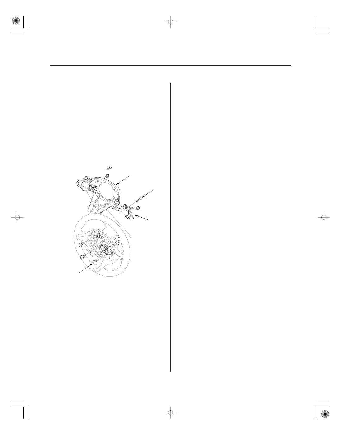
1. Remove the steering wheel (see page 17-6).
2. Remove the paddle shifter
(upshift switch) and
the paddle shifter
(downshift switch) connectors
from the connector holder, and disconnect the
connectors.
3. Remove the screws (A) securing the paddle
shifter
(upshift switch) and the paddle shifter
(downshift switch).
4. Remove the screws (B) securing the steering wheel
rear cover (C), then remove the steering wheel rear
cover.
5. Remove the paddle shifter
(upshift switch) (D)
from the rear cover.
6. Install a new paddle shifter
(upshift switch) in the
steering wheel rear cover.
7. Install the steering wheel rear cover, and secure the
rear cover with the screws.
8. Secure the paddle shifter
(upshift switch) and the
paddle shifter
(downshift switch) with the screws.
9. Connect the paddle shifter
(upshift switch) and
the paddle shifter
(downshift switch) connector,
and install the connectors in the connector holder.
10. Install the steering wheel (see page 17-8).
08/08/21 14:50:02 61SNR030_140_0278