Acura CSX. Manual - part 241
*04
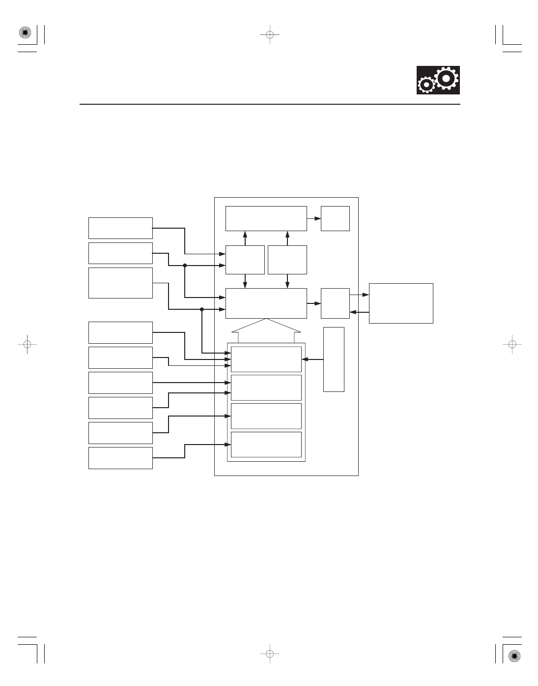
Clutch Pressure Control
14-45
PCM
Engine RPM Signal
Engine Coolant
Temperature
Sensor Signal
Input Shaft
(Mainshaft)
Speed Sensor Signal
Output Shaft
(Countershaft)
Speed Sensor Signal
ATF Temperature
Sensor Signal
Actual
Driving Shift
Position
Correction of Data
Correction of Engine
Coolant Temperature
Sensor Data
Manifold Absolute
Pressure Sensor Signal
3rd Clutch
Transmission Fluid
Pressure Switch Signal
2nd Clutch
Transmission Fluid
Pressure Switch Signal
Correction of ATF
Temperature Sensor
Signal Data
Correction of
Hydraulic Pressure
Applying Timing
Correction of Engine
Torque Signal Data
Master Target of
Controlling Current
Decision of
Shifting Mode
Ignition Timing
Requirement
PGM-FI
Control
System
Current
Feedback
A/T Clutch Pressure
Control Solenoid
Valves A, B, and C
PGM-FI
Control
System
Throttle Position
Sensor Signal
B
a
ro
me
tr
ic
P
re
s
s
u
re
Sensor
Si
gnal
The PCM actuates A/T clutch pressure control solenoid valves A, B, and C to control the clutch pressure. When shifting
between lower and higher gears, the clutch pressure regulated by A/T clutch pressure control solenoid valves A, B,
and C engages and disengages the clutch smoothly.
The PCM receives input signals from the various sensors and the switches, processes data, and outputs current to A/T
clutch pressure control solenoid valves A, B, and C.
08/08/21 14:38:23 61SNR030_140_0047