Acura CSX. Manual - part 227
10
11
12
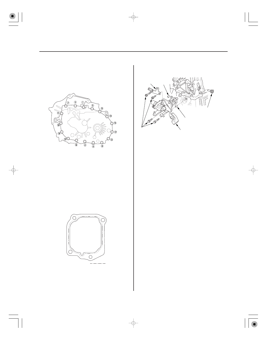
Specified Torque:
8 x 1.25 mm
27 N·m (2.8 kgf·m, 20 lbf·ft)
13-136
Manual Transmission
Liquid gasket
A
C
B
6 x 1.0 mm
12 N·m
(1.2 kgf·m,
8.7 lbf·ft)
D
39 N·m
(4.0 kgf·m,
29 lbf·ft)
B
14. Tighten the 8 mm flange bolts in a crisscross
pattern in several steps.
15. Clean any dirt or oil from the mating surface of the
change lever assembly and the transmission
housing. Apply liquid gasket, P/N 08718-0001,
evenly to the mating surface of the change lever
assembly and the transmission housing. Install the
component within 5 minutes of applying the liquid
gasket.
NOTE:
• If you apply liquid gasket P/N 08718-0012, the
component must be installed within 4 minutes.
• If too much time has passed after applying the
liquid gasket, remove the old liquid gasket and
residue, then reapply new liquid gasket.
16. Install the 8 x 14 mm dowel pins (B) and the change
lever assembly (C) with harness bracket A.
17. Apply liquid gasket, P/N 08718-0001, evenly to the
threads of the inter lock bolt (D). Install the
component within 5 minutes of applying the liquid
gasket.
NOTE:
• If you apply liquid gasket P/N 08718-0012, the
component must be installed within 4 minutes.
• If too much time has passed after applying the
liquid gasket, remove the old liquid gasket and
residue, then reapply new liquid gasket.
08/08/21 14:48:44 61SNR030_130_0138