Acura CSX. Manual - part 168
04
SNR9A00A20326437601FEAT00
11-341
11-341
Low Fuel Indicator Test
F
1/2
E LOW
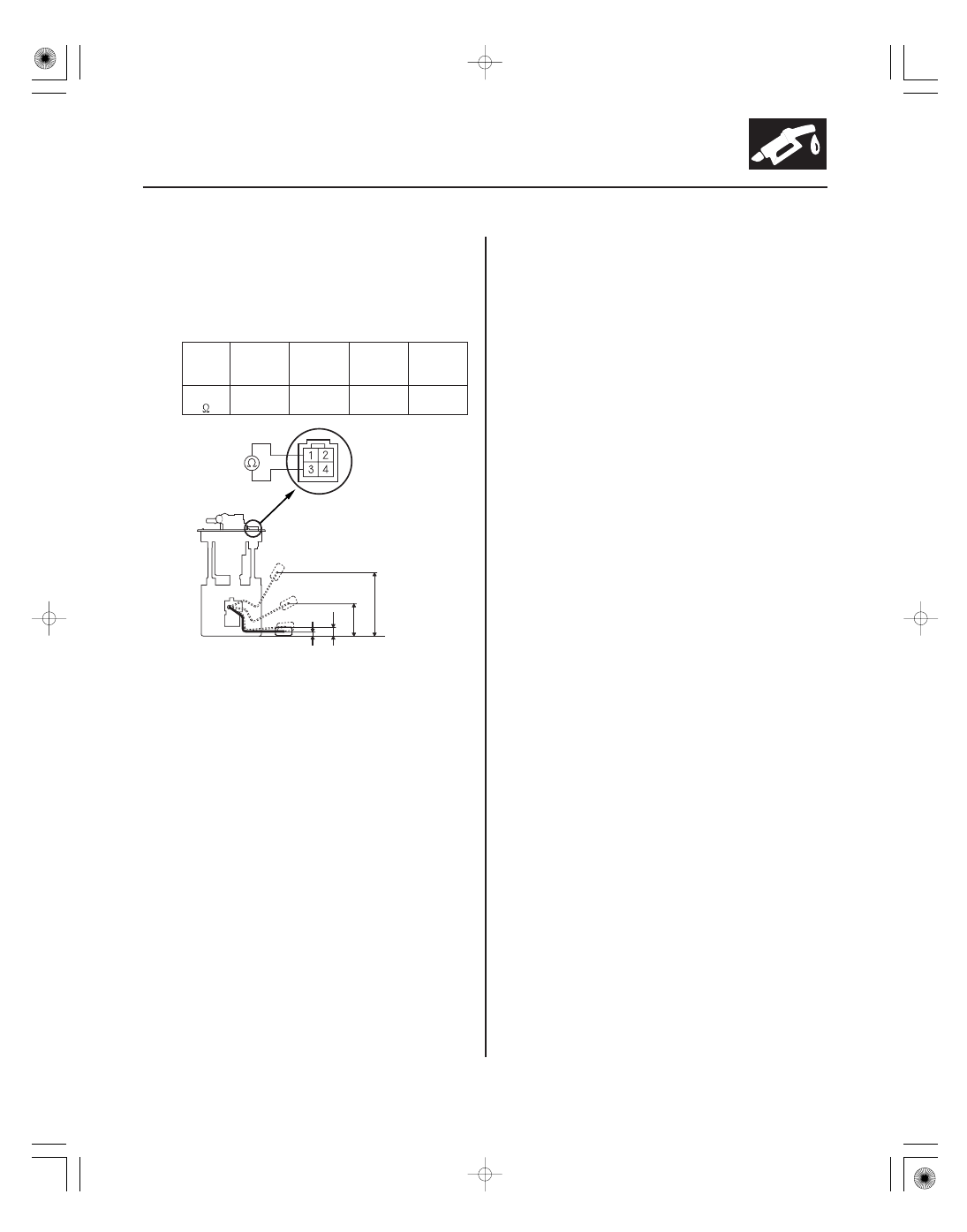
11. Measure the resistance between fuel tank unit 4P
connector terminals No. 1 and No. 3 with the float
at E (EMPTY), LOW (LOW FUEL INDICATOR), 1/2
(HALF FULL), and F (FULL) positions.
If you do not get the following readings, replace the
fuel gauge sending unit (see page 11-338).
F
139.8 mm
(5.5 in.)
1/2
72.1 mm
(2.8 in.)
LOW
19.5 mm
(0.77 in.)
E
8.9 mm
(0.35 in.)
(
)
19 to
21
205.8 to
215.8
537.5 to
707
772 to
788
12. Reconnect the fuel tank unit 4P connector.
13. Remove the No. 23 BACK UP (10 A) fuse from the
under-hood fuse/relay box for at least 10 seconds,
then reinstall it.
14. Turn the ignition switch to ON (II).
15. Check that the pointer of the fuel gauge indicates F
with the float at F.
• If the pointer of the fuel gauge does not indicate F,
replace the gauge assembly.
• If the gauge is OK, the test is complete.
NOTE:
• The pointer of the fuel gauge returns to the
bottom of the gauge dial when the ignition switch
is turned to ACC or to LOCK (0), regardless of the
fuel level.
• Remove the No. 23 BACK UP (10 A) fuse from the
under-hood fuse/relay box for at least 10 seconds
after completing troubleshooting, otherwise it
may take up to 20 minutes for the fuel gauge to
indicate the correct fuel level.
1. Do the gauge self-diagnostic function (see page
22-241).
• If the low fuel indicator flashes, go to step 2.
• If the low fuel indicator does not flash, replace
the gauge control module (tach) (see page
22-277).
2. Check for body electrical system DTCs.
• If any DTCs are indicated, do the indicated DTC’s
troubleshooting.
• If no DTCs are indicated, go to step 3.
3. Do the fuel gauge sending unit test (see page
11-340).
Float
Position
Resistance
Terminal side of
male terminals
08/08/21 14:31:02 61SNR030_110_0341