Acura CSX. Manual - part 141
01
02
−
−
−
−
YES
NO
YES
NO
11-237
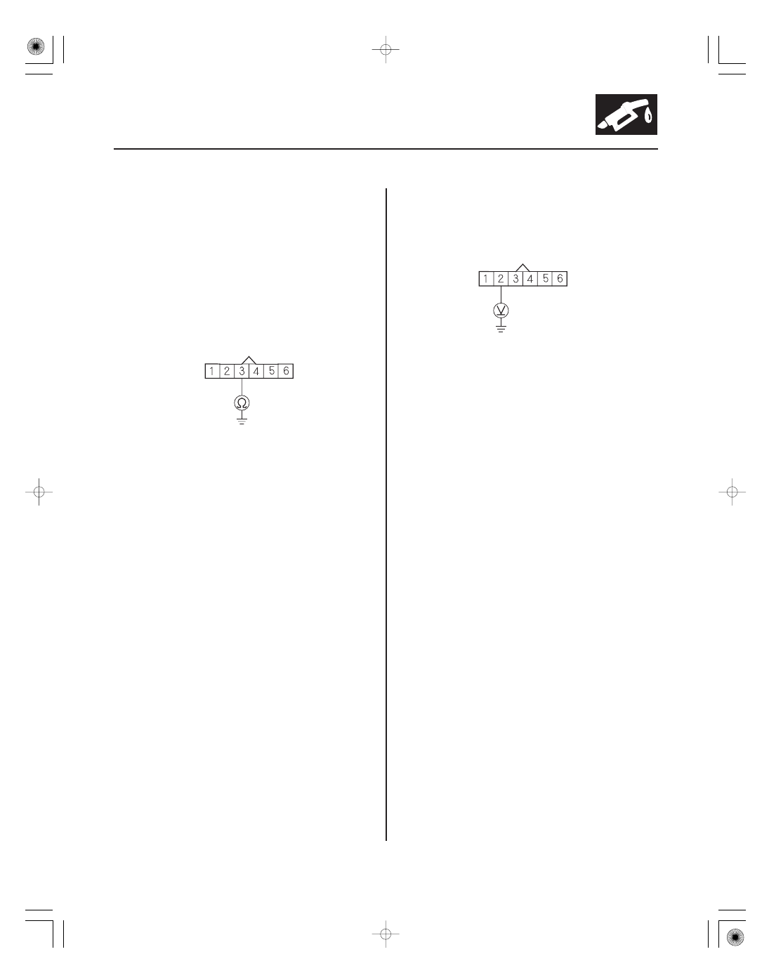
THROTTLE BODY 6P CONNECTOR
TPSB (RED/BLU)
THROTTLE BODY 6P CONNECTOR
VCC3 (BLU)
5. Turn the ignition switch to LOCK (0).
6. Disconnect the throttle body 6P connector.
7. Jump the SCS line with the HDS.
8. Disconnect ECM/PCM connector C (44P).
9. Check for continuity between throttle body 6P
connector terminal No. 3 and body ground.
Repair short in the wire between the throttle
body and the ECM/PCM (C21), then go to step 18.
Go to step 23.
10. Measure the voltage between throttle body 6P
connector terminal No. 2 and body ground.
Go to step 16.
Go to step 11.
11. Turn the ignition switch to LOCK (0).
12. Jump the SCS line with the HDS.
13. Disconnect ECM/PCM connector C (44P).
14. Disconnect the throttle body 6P connector.
Wire side of female terminals
Wire side of female terminals
Is ther e continuity?
Is ther e about 5 V ?
08/08/21 14:23:44 61SNR030_110_0237