Acura CSX. Manual - part 113
−
01
SNR9AA7K72100090325FAAT00
−
−
−
−
−
−
YES
NO
YES
NO
YES
NO
DTC P0325:
11-126
11-126
PGM-FI System
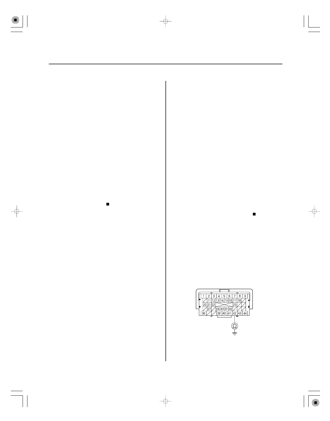
ECM/PCM CONNECTOR C (44P)
KS (RED/BLU)
72. Check for Temporary DTCs or DTCs with the HDS.
Check for poor connections or loose
terminals at the ignition coil(s), the injector(s), and
the ECM/PCM. If the ECM/PCM was updated,
substitute a known-good ECM/PCM (see page 11-7),
then go to step 71. If the ECM/PCM was substituted,
go to step 1.
Go to step 73.
73. Monitor the OBD STATUS for DTC P0301, P0302,
P0303, or P0304 in the DTCs MENU with the HDS.
If the ECM/PCM was updated,
troubleshooting is complete. If the ECM/PCM was
substituted, replace the original ECM/PCM
(see page 11-228). If any other Temporary DTCs or
DTCs were indicated in step 72, go to the indicated
DTC’s troubleshooting.
If the screen indicates FAILED, check for poor
connections or loose terminals at the ignition coil,
the injector, and the ECM/PCM. If the ECM/PCM
was updated, substitute a known-good ECM/PCM
(see page 11-7), then go to step 71. If the ECM/PCM
was substituted, go to step 1. If the screen indicates
EXECUTING, keep driving until a result comes on. If
the screen indicates OUT OF CONDITION, go to
step 71.
NOTE: Before you troubleshoot, record all freeze data
and any on-board snapshot, and review the general
troubleshooting information (see page 11-3).
1. Turn the ignition switch to ON (II).
2. Clear the DTC with the HDS.
3. Start the engine. Hold the engine speed between
3,000 rpm without load (A/T in P or N, M/T in
neutral) until the radiator fan comes on, then let it
idle.
4. Hold the engine speed between 3,000
4,000 rpm
for at least 10 seconds.
5. Check for Temporary DTCs or DTCs with the HDS.
Go to step 6.
Intermittent failure, the system is OK at this
time. Check for poor connections or loose terminals
at the knock sensor and the ECM/PCM.
6. Turn the ignition switch to LOCK (0).
7. Jump the SCS line with the HDS.
8. Disconnect the knock sensor 1P connector
(see page 11-223).
9. Disconnect ECM/PCM connector C (44P).
10. Check for continuity between ECM/PCM connector
terminal C42 and body ground.
Knock Sensor Circuit Malfunction
Terminal side of female terminals
Is DT C P0301, P0302, P0303, or P0304
indicated?
Does the scr een indicate PASSED?
Is DT C P0325 indicated?
08/08/21 14:18:52 61SNR030_110_0126