Acura CSX. Manual - part 47


  Index      Acura     Acura CSX - P/NO. 61SNR03 - service repair manual 2006-2009 year


Search            


Content   ..  45  46  47  48   ..


Acura CSX. Manual - part 47


06

07

6-40

Cylinder Head

B

A

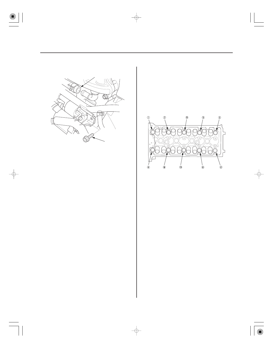
12. Remove the bolt (A) securing the connecting pipe.

13. Disconnect the water bypass hose (B).

14. Disconnect the following engine wire harness

connectors, and remove the wire harness clamps
from the cylinder head.

• Four fuel injector connectors
• Engine coolant temperature (ECT) sensor 1

connector

• Camshaft position (CMP) sensor A (Intake)

connector

• Camshaft position (CMP) sensor B (Exhaust)

connector

• Rocker arm oil control valve connector
• Rocker arm oil pressure switch connector
• EVAP canister purge valve connector
• Variable valve timing control (VTC) oil control

solenoid valve connector

• Exhaust gas recirculation (EGR) valve connector

(K20Z2 engine)

• Engine oil pressure switch connector

15. Remove the cam chain (see page 6-18).

16. Remove the rocker arm assembly:

• K20Z2 engine (see page 6-43)
• K20Z3 engine (see page 6-44)

17. Remove the cylinder head bolts. To prevent

warpage, loosen the bolts in sequence 1/3 turn at a
time. Repeat the sequence until all bolts are
loosened.

18. Remove the cylinder head.

01

01

SNR9A00A14616716091KBAT10

03

02

SNR9A00A14616716091KBAT20

6-41

6-41

CMP Pulse Plate A Replacement

CMP Pulse Plate B Replacement

14 x 1.0 mm
39 N·m
(4.0 kgf·m, 29 lbf·ft)

14 x 1.0 mm
39 N·m
(4.0 kgf·m, 29 lbf·ft)

1. Remove the cylinder head cover (see page 6-36).

2. Remove camshaft position (CMP) sensor A

(see page 11-295).

3. Hold the intake camshaft with an open-end wrench,

then loosen the bolt.

4. Remove CMP pulse plate A.

5. Install CMP pulse plate A in the reverse order of

removal.

1. Remove the cylinder head cover (see page 6-36).

2. Remove camshaft position (CMP) sensor B

(see page 11-222).

3. Hold the exhaust camshaft with an open-end

wrench, then loosen the bolt.

4. Remove CMP pulse plate B.

5. Install CMP pulse plate B in the reverse order of

removal.

Apply new engine oil to the
bolt threads.

Apply new engine oil to the
bolt threads.

01

02

SNR9A00A14680463351KBAT00

Removal

Installation

Specified Torque
VTC Actuator Mounting Bolt:
12 x 1.25 mm
113 N·m (11.5 kgf·m, 83 lbf·ft)
Exhaust Camshaft Sprocket Mounting Bolt:
10 x 1.25 mm
72 N·m (7.3 kgf·m, 53 lbf·ft)

6-42

Cylinder Head

VTC Actuator, Exhaust Camshaft Sprocket Replacement

1. Remove the cam chain (see page 6-18).

2. Hold the exhaust camshaft with an open-end

wrench, then loosen the variable valve timing
control (VTC) actuator mounting bolt and the
exhaust camshaft sprocket mounting bolt.

3. If the VTC actuator is reused, do these steps.

–1 Remove the intake camshaft, and seal the

advance holes and retard holes in the No. 1
camshaft journal with tape (see step 6 on page
6-11).

–2 Punch a hole in the tape over one of the

advance holes (see step 7 on page 6-11).

–3 Apply air to the advance hole to release the

lock (see step 8 on page 6-11).

–4 Remove the tape from the No. 1 camshaft

journal.

4. Remove the VTC actuator and the exhaust

camshaft sprocket.

1. Install the variable valve timing control (VTC)

actuator and exhaust camshaft sprocket.

NOTE: Install the VTC actuator to unlock position.

2. Apply new engine oil to the threads of the VTC

actuator mounting bolt and the exhaust camshaft
mounting bolt, then install them.

3. Hold the exhaust camshaft with an open-end

wrench, then tighten the mounting bolts.

4. Hold the exhaust camshaft with an open-end

wrench, and turn the VTC actuator clockwise until
you hear it click. Make sure to lock the VTC actuator
by turning it.

5. Install the cam chain (see page 6-21).

01

02

SNR9A00A14600017801MAAT00

*01

02

SNR9AEAA14666300000KAAT02

Cylinder Head Height
Standard (New): 103.95

104.05 mm

(4.093

4.096 in.)

K20Z2 engine

6-43

6-43

Cylinder Head Inspection for
Warpage

Rocker Arm Assembly Removal

PRECISION STRAIGHT EDGE

A

A

1. Remove the cylinder head (see page 6-38).

2. Inspect the camshaft:

• K20Z2 engine (see page 6-50)
• K20Z3 engine (see page 6-52)

3. Check the cylinder head for warpage. Measure

along the edges, and three ways across the center.

• If warpage is less than 0.05 mm (0.002 in.)

cylinder head resurfacing is not required.

• If warpage is between 0.05 mm (0.002 in.) and

0.2 mm (0.008 in.), resurface the cylinder head.

• Maximum resurface limit is 0.2 mm (0.008 in.)

based on a height of 104 mm (4.09 in.).

1. Remove the cam chain (see page 6-18).

2. Loosen the rocker arm adjusting screws (A).

3. Remove the camshaft holder bolts. To prevent

damaging the camshafts, loosen the bolts, in
sequence, two turns at a time in a crisscross
pattern.


Content   ..  45  46  47  48   ..