Intel 64 and IA-32 Architectures. Software Developer’s Manual (Collection, 2023) - page 145
SOFTWARE OPTIMIZATION FOR INTEL® AVX-512 INSTRUCTIONS
… 63 32 31
0 bits
31
29
7
1
3
ZMM0
… 63
32 31
0 bits
a15
a14
a13
a12
a11
a10
a9
a8
a7
a6
a5
a4
a3
a2
a1
a0
ZMM1
15
14
13
12
11
10
9
8
7
6
5
4
3
2
1
0
index
… 63 32 31
0 bits
b15
b14
b13
b12
b11
b10
b9
b8
b7
b6
b5
b4
b3
b2
b1
b0
ZMM2
31
30
29
28
27
26
25
24
23
22
21
20
19
18
17
16
index
… 63
32 31
0 bits
b15
b13
a7
a1
a3
ZMM0
SOM00011
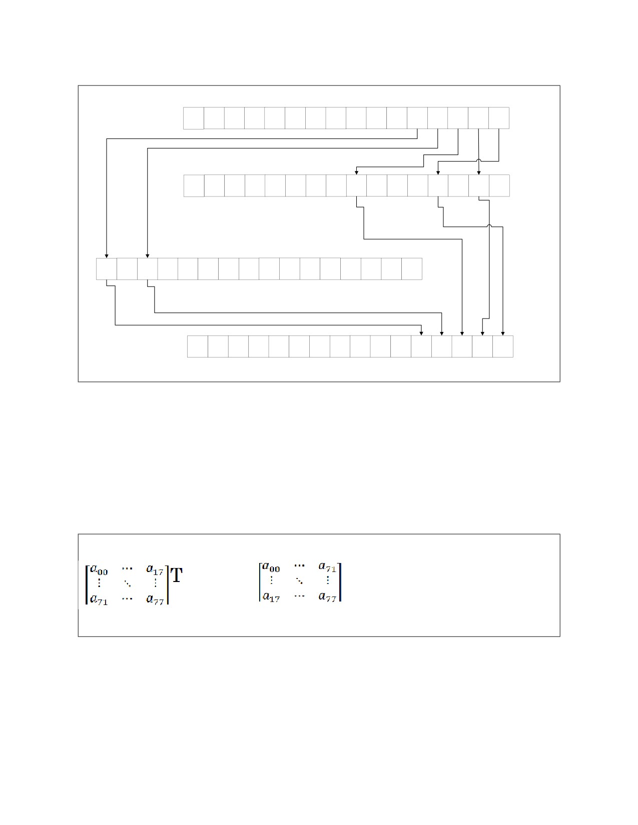
Figure 18-8. VPERMI2PS Instruction Operation
Note that the index register values must have the same resolution as the instruction and source registers
(word when working on words, dword when working on dwords, etc.).
18.8.1 Two Source Permute Example
In this example we will show the use of the two source permute instructions in a matrix transpose oper-
ation. The matrix we want to transpose is square 8x8 matrix of word elements.
→
18-29
SOFTWARE OPTIMIZATION FOR INTEL® AVX-512 INSTRUCTIONS
The corresponding C code is as follows (assuming each matrix occupies a continuous block of 8*8*2 =
128 bytes):
for(int iY = 0; iY < 8; iY++)
{
for(int iX = 0; iX < 8; iX++)
{
trasposedMatrix[iY*8+iX] = originalMatrix[iX*8+iY];
}
}
Here are three implementations for this matrix transpose.
• Alternative 1 is scalar code, which accesses each element of the source matrix and puts it to the
corresponding place in the destination matrix. This code does 64 (8x8) iterations per 1 matrix.
• Alternative 2 is Intel AVX2 code, which uses Intel AVX2 permutation and shuffle (unpack) instruc-
tions. Only 1 iteration per 8x8 matrix is required.
• Alternative 3 Intel AVX-512 code which uses the Two Source Permutation instructions. Note that this
code first loads permutation masks, and then matrix data. The mask used to perform the
permutation is stored in the following array:
short permMaskBuffer [8*8] = { 0, 8, 16, 24, 32, 40, 48, 56,
1, 9, 17, 25, 33, 41, 49, 57,
2, 10, 18, 26, 34, 42, 50, 58,
3, 11, 19, 27, 35, 43, 51, 59,
4, 12, 20, 28, 36, 44, 52, 60,
5, 13, 21, 29, 37, 45, 53, 61,
6, 14, 22, 30, 38, 46, 54, 62,
7, 15, 23, 31, 39, 47, 55, 63 };
Each alternative transposes 50 matrixes, 8x8 2-byte elements each.
18-30

SOFTWARE OPTIMIZATION FOR INTEL® AVX-512 INSTRUCTIONS
Example 18-13. Matrix Transpose Alternatives
Alternative 1: Scalar code
Alternative 2: Intel® AVX2 Code
Alternative 3: Intel® AVX-512 Code
mov rsi, pImage
mov rsi, pImage
mov rax, permMaskBuffer
mov rdi, pOutImage
mov rdi, pOutImage
vmovdqa32 zmm10, [rax]
xor rdx, rdx
xor rdx, rdx
vmovdqa32 zmm11, [rax+0x40]
matrix_loop:
matrix_loop:
mov rsi, pImage
xor rax, rax
vmovdqa xmm0, [rsi]
mov rdi, pOutImage
outerloop:
vmovdqa xmm1, [rsi+0x10]
xor rdx, rdx
xor rbx, rbx
vmovdqa xmm2, [rsi+0x20]
matrix_loop:
innerloop:
vmovdqa xmm3, [rsi+0x30]
vmovdqa32 zmm2, [rsi]
mov rcx, rax
vmovdqa32 zmm3, [rsi+0x40]
shl rcx, 3
vinserti128 ymm0, ymm0,
vmovdqa32 zmm0, zmm10
add rcx, rbx
[rsi+0x40], 0x1
vmovdqa32 zmm1, zmm11
mov r8w, word ptr [rsi+rcx*2]
vinserti128 ymm1, ymm1,
vpermi2w zmm0, zmm2, zmm3
mov rcx, rbx
[rsi+0x50], 0x1
vpermi2w zmm1, zmm2, zmm3
shl rcx, 3
vinserti128 ymm2, ymm2,
vmovdqa32 [rdi], zmm0
[rsi+0x60], 0x1
add rcx, rax
vmovdqa32 [rdi+0x40], zmm1
vinserti128 ymm3, ymm3,
mov word ptr [rdi+rcx*2], r8w
[rsi+0x70], 0x1
add rbx, 1
add rdx, 1
cmp rbx, 8
add rsi, 64*2
vpunpcklwd ymm4, ymm0, ymm1
jne innerloop
add rdi, 64*2
vpunpckhwd ymm5, ymm0, ymm1
add rax, 1
cmp rdx, 50
vpunpcklwd ymm6, ymm2, ymm3
cmp rax, 8
jne matrix_loop
vpunpckhwd ymm7, ymm2, ymm3
jne outerloop
add rdx, 1
vpunpckldq ymm0, ymm4, ymm6
add rsi, 64*2
vpunpckhdq ymm1, ymm4, ymm6
add rdi, 64*2
vpunpckldq ymm2, ymm5, ymm7
cmp rdx, 50
vpunpckhdq ymm3, ymm5, ymm7
jne matrix_loop
vpermq ymm0, ymm0, 0xD8
vpermq ymm1, ymm1, 0xD8
vpermq ymm2, ymm2, 0xD8
vpermq ymm3, ymm3, 0xD8
vmovdqa [rdi], ymm0
vmovdqa [rdi+0x20], ymm1
vmovdqa [rdi+0x40], ymm2
vmovdqa [rdi+0x60], ymm3
add rdx, 1
add rsi, 64*2
add rdi, 64*2
cmp rdx, 50
jne matrix_loop
Baseline 1x
Speedup: 13.7x
Speedup: 37.3x
(2.7x vs Intel® AVX2 code)
18-31

SOFTWARE OPTIMIZATION FOR INTEL® AVX-512 INSTRUCTIONS
18.9
BROADCAST
18.9.1 Embedded Broadcast
Intel AVX-512 introduces embedded broadcast operations, in which a broadcast operation is implied
within the syntax of a non-broadcast instruction. A source from memory can be broadcast, that is,
repeated, across all the elements of the effective source operand, up to 16 times for a 32-bit data
element, and up to 8 times for a 64-bit data element, without using an additional source register. This is
useful when we want to reuse the same scalar operand for all the operations in a vector instruction.
Embedded broadcast is only enabled on instructions with an element size of 32 or 64 bits; however, new
FP16 instructions allow embedded broadcast. Please see Section 19.4.7, “FP16 Conversions to and from
Other Data Types” for more information. In the case of older technologies, byte and word element broad-
casts do not support embedded broadcast. Use a broadcast instruction, rather than embedded broad-
cast, to broadcast a byte or word.
Using embedded broadcast can reduce the number of registers used in the code, which may be helpful
when register pressure exists.
In addition, when using embedded broadcast the load micro-op is in the same instruction as the opera-
tion micro-op, and therefore can benefit from micro fusion.
For example, replace the following code:
vbroadcastss zmm3, [rax]
vmulps zmm1, zmm2, zmm3
with:
vmulps zmm1, zmm2, [rax] {1to16}
The {1to16} primitive does the following:
1. Loads one float32 (single precision) element from memory.
2. Replicates it 16 times to form a vector of 16 32-bit floating point elements.
Intel AVX-512 instructions with store semantics and pure load instructions do not support broadcast
primitives.
18.9.2 Broadcast Executed on Load Ports
In Skylake Server microarchitecture, a broadcast instruction with a memory operand of 32 bits or above
is executed on the load ports; it is not executed on port 5 as other shuffles are. Alternative 2 in the
following example shows how executing the broadcast on the load ports reduces the workload on port 5
and increases performance. Alternative 3 shows how embedded broadcast benefits from both executing
the broadcast on the load ports and micro fusion.
Example 18-14. Broadcast Executed on Load Ports Alternatives
Alternative 1: 32-bit Load and
Alternative 2: Broadcast with a 32-
Alternative 3: 32-bit Embedded
Register Broadcast
bit Memory Operand
Broadcast
loop:
loop:
loop:
vmovd xmm0, [rax]
vpbroadcastd zmm0, [rax]
vpaddd zmm2, zmm1, [rax]{1to16}
vpbroadcastd zmm0, xmm0
vpaddd zmm2, zmm1, zmm0
vpermd zmm2, zmm3, zmm2
vpaddd zmm2, zmm1, zmm0
vpermd zmm2, zmm3, zmm2
add rax, 0x4
vpermd zmm2, zmm3, zmm2
add rax, 0x4
sub rdx, 0x1
add rax, 0x4
sub rdx, 0x1
jnz loop
sub rdx, 0x1
jnz loop
jnz loop
18-32

SOFTWARE OPTIMIZATION FOR INTEL® AVX-512 INSTRUCTIONS
Example 18-14. Broadcast Executed on Load Ports Alternatives (Contd.)
Alternative 1: 32-bit Load and
Alternative 2: Broadcast with a 32-
Alternative 3: 32-bit Embedded
Register Broadcast
bit Memory Operand
Broadcast
Baseline 1x
Speedup: 1.57x
Speedup: 1.9x
The following example shows that on Skylake Server microarchitecture, 16-bit broadcast is executed on
port 5 and therefore does not gain from the memory operand broadcast.
Example 18-15. 16-bit Broadcast Executed on Port 5
Alternative 1: 16-bit Load and Register Broadcast
Alternative 2: Broadcast with a 16-bit Memory Operand
loop:
loop:
vmovd xmm0, [rax]
vpbroadcastw zmm0, [rax]
vpbroadcastw zmm0, xmm0
vpaddw zmm2, zmm1, zmm0
vpaddw zmm2, zmm1, zmm0
vpermw zmm2, zmm3, zmm2
vpermw zmm2, zmm3, zmm2
add rax, 0x2
add rax, 0x4
sub rdx, 0x1
sub rdx, 0x1
jnz loop
jnz loop
Baseline 1x
Speedup: equal to baseline
Notice that embedded broadcast is not supported for 16-bit memory operands.
18.10 EMBEDDED ROUNDING
By default, the Rounding Mode is set by bits 13:14 of the MXCSR register.
Intel AVX-512 introduces a new instruction attribute called Static (per instruction) Rounding Mode (RM)
or Rounding Mode override. This attribute allows a specific arithmetic rounding mode to be applied,
ignoring the value of the RM bits in the MXCSR. In combination with the rounding-mode, Intel AVX-512
also has an SAE (“suppress-all-exceptions”) attribute, to disable reporting any floating-point exception
flag in the MXCSR. SAE is always implied when rounding-mode is enabled.
Static Rounding Mode and SAE control can be enabled in the encoding of the instruction by setting the
EVEX.b bit to 1 in a register-register vector instruction. In this case, vector length is assumed to be the
maximal possible vector length (512-bit in case of Intel AVX-512). The table below summarizes the
possible static rounding-mode assignments in Intel AVX-512. Note that some instructions already allow
the rounding mode to be statically specified via immediate bits. In such case, the immediate bits take
precedence over the embedded rounding mode in the same way as they take precedence over the bits in
MXCSR.RM
18.10.1 Static Rounding Mode
Static rounding mode functions and descriptions are listed below.
18-33

SOFTWARE OPTIMIZATION FOR INTEL® AVX-512 INSTRUCTIONS
Table 18-2. Static Rounding Mode Functions
Function
Description
{rn-sae}
Round to nearest (even) + SAE
{rd-sae}
Round down (toward -infinity) + SAE
{ru-sae}
Round up (toward +infinity) + SAE
{rz-sae}
Round toward zero (Truncate) + SAE
The following code snippet shows a usage example.
Example 18-16. Embedded vs Non-embedded Rounding
Using Embedded Rounding
Without Embedded Rounding
;rax & rcx point to temporary dword values in memory used
to load and save (for restoring) MXCSR value
vaddps zmm7 {k6}, zmm2, zmm4, {ru-sae}
vstmxcsr [rax]
;load mxcsr value to memory
mov ebx, [rax]
;move to register
and ebx, 0xFFFF9FFF ;zero RM bits
or ebx, 0x5F80
;put {ru} to RM bits and suppress all
exceptions
mov [rcx], ebx
;move new value to the memory
vldmxcsr [rcx]
;save to MXCSR
vaddps zmm7 {k6}, zmm2, zmm4 ;operation itself
vldmxcsr [rax]
;restore previous MXCSR value
This piece of code would perform the single-precision floating point addition of vectors zmm2 and zmm4
with round-towards-plus-infinity, leaving the result in vector zmm7 using k6 as a conditional writemask.
Note that MXCSR.RM bits are ignored and unaffected by the outcome of this instruction.
The following are examples of instructions instances where the static rounding-mode is not allowed.
; rounding-mode already specified in the instruction immediate
vrndscaleps zmm7 {k6}, zmm2 {rd}, 0x00
; instructions with memory operands
vmulps zmm7 {k6}, zmm2, [rax] {rd}
; instructions with vector length different than maximal vector length (512-bit)
vaddps ymm7 {k6}, ymm2, ymm4 {rd}
; non-floating point instructions
vpaddd zmm7 {k6}, zmm2, zmm4 {rd}
18-34

SOFTWARE OPTIMIZATION FOR INTEL® AVX-512 INSTRUCTIONS
18.11 SCATTER INSTRUCTION
This instruction performs a non-continuous store of data (scatter). Given a base address, a set of signed
offsets and a data item, the instruction writes each element in the data register to the memory location
computed from the base address and corresponding offset. The instruction stores up to 16 elements (8
elements for qword indices) in a doubleword vector or 8 elements in a quadword vector, to the memory
locations pointed to by the base address and index vector. Elements are stored only if their corresponding
mask bit is one. The figure below describes the following operation.
vscatterdpd
[rax + zmm0]{k1} , zmm1
In this example, rax contains the base address, zmm0 contains a set of offsets, and zmm1 contains data to
be written.
… 63 32 31
0 bits
a15
a14
a13
a12
a11
a10
a9
a8
a7
a6
a5
a4
a3
a2
a1
a0
Data
… 63
32 31
0 bits
b15
b14
b13
b12
b11
b10
b9
b8
b7
b6
b5
b4
b3
b2
b1
b0
Offset
Base
GPR
Address
(BA)
Mem at
Mem at
Mem at
ax
a1
a0
[BA+bx]
[BA+b1]
[BA+b0]
SOM00012
Figure 18-9. VSCATTERDPD Instruction Operation
18.11.1 Data Scatter Example
Given an array of unique indexes, ranging from 0 to N, we want to sort the array of N values, according
to the corresponding index, while converting the values from long long integers (64 bits) to floating point
numbers (32 bits).
for ( int i=0; i < N; i++ )
{
dst[ ind [i] ] = (float)src[i];
}
Here are three implementations of the code above.
18-35

SOFTWARE OPTIMIZATION FOR INTEL® AVX-512 INSTRUCTIONS
• Alternative 1 is pure scalar code.
• Alternative 2 is a software sequence for scatter.
• Alternative 3 is a hardware scatter.
NOTE
A hardware Scatter operation issues as many store operations, as the number of
elements in the vector. Do not use a scatter operation to store sequential elements, which
can be stored with one vmov instruction.
Example 18-17. Scatter
Scalar
mov rax, pImage
//input
mov rcx, pOutImage //output
mov rbx, pIndex
//indexes
mov rdx, len
//length
xor r9, r9
mainloop:
mov r9d, [rbx+rdx-0x4]
vcvtsi2ss xmm0, xmm0, qword ptr [rax+rdx*2-0x8]
vmovss [rcx+r9*4], xmm0
sub rdx, 4
jnz mainloop
Baseline 1x
Software Sequence
Hardware Scatter
18-36

SOFTWARE OPTIMIZATION FOR INTEL® AVX-512 INSTRUCTIONS
Example 18-17. Scatter
shufMaskP:
mov rax, pImage
//input
.quad·0x0000000200000001
mov rcx, pOutImage //output
.quad·0x0000000400000003
mov rbx, pIndex
//indexes
.quad·0x0000000600000005
mov rdx, len
//length
.quad·0x0000000800000007
mainloop:
vmovdqa32 zmm0, [rbx+rdx-0x40]
mov rax, pImage
//input
vmovdqa32 zmm1, [rax+rdx*2-0x80]
mov rcx, pOutImage //output
vcvtuqq2ps ymm1, zmm1
mov rbx, pIndex
//indexes
vmovdqa32 zmm2, [rax+rdx*2-0x40]
mov rdx, len
//length
vcvtuqq2ps ymm2, zmm2
mov r9, shufMaskP
vshuff32x4 zmm1, zmm1, zmm2, 0x44
vmovaps ymm2, [r9]
kxnorw k1,k1,k1
mainloop:
vscatterdps [rcx+4*zmm0] {k1}, zmm1
vmovaps zmm1, [rax + rdx*2 - 0x80] //load data
sub rdx, 0x40
vcvtuqq2ps ymm0, zmm1 //convert to float
jnz mainloop
movsxd r9, [rbx + rdx - 0x40] //load 8th index
vmovss [rcx + 4*r9], xmm0
vpermd ymm0, ymm2, ymm0
movsxd r9, [rbx + rdx - 0x3c] //load 7th index
vmovss [rcx + 4*r9], xmm0
vpermd ymm0, ymm2, ymm0
movsxd r9, [rbx + rdx - 0x38] //load 6th index
vmovss [rcx + 4*r9], xmm0
vpermd ymm0, ymm2, ymm0
movsxd r9, [rbx + rdx - 0x34] //load 5th index
vmovss [rcx + 4*r9], xmm0
vpermd ymm0, ymm2, ymm0
movsxd r9, [rbx + rdx - 0x30] //load 4th index
vmovss [rcx + 4*r9], xmm0
vpermd ymm0, ymm2, ymm0
movsxd r9, [rbx + rdx - 0x2c] //load 3rd index
vmovss [rcx + 4*r9], xmm0
vpermd ymm0, ymm2, ymm0
18-37

SOFTWARE OPTIMIZATION FOR INTEL® AVX-512 INSTRUCTIONS
Example 18-17. Scatter
movsxd r9, [rbx + rdx - 0x28] //load 2nd index
vmovss [rcx + 4*r9], xmm0
vpermd ymm0, ymm2, ymm0
movsxd r9, [rbx + rdx - 0x24] //load 1st index
vmovss [rcx + 4*r9], xmm0
vmovaps zmm1, [rax + rdx*2 - 0x40] //load data
vcvtuqq2ps ymm0, zmm1 //convert to float
movsxd r9, [rbx + rdx - 0x20] //load 8th index
vmovss [rcx + 4*r9], xmm0
vpermd ymm0, ymm2, ymm0
movsxd r9, [rbx + rdx - 0x1c] //load 7th index
vmovss [rcx + 4*r9], xmm0
vpermd ymm0, ymm2, ymm0
movsxd r9, [rbx + rdx - 0x18] //load 6th index
vmovss [rcx + 4*r9], xmm0
vpermd ymm0, ymm2, ymm0
movsxd r9, [rbx + rdx - 0x14] //load 5th index
vmovss [rcx + 4*r9], xmm0
vpermd ymm0, ymm2, ymm0
movsxd r9, [rbx + rdx - 0x10] //load 4th index
vmovss [rcx + 4*r9], xmm0
vpermd ymm0, ymm2, ymm0
movsxd r9, [rbx + rdx - 0xc] //load 3rd index
vmovss [rcx + 4*r9], xmm0
vpermd ymm0, ymm2, ymm0
movsxd r9, [rbx + rdx - 0x8] //load 2nd index
vmovss [rcx + 4*r9], xmm0
vpermd ymm0, ymm2, ymm0
movsxd r9, [rbx + rdx - 0x4] //load 1st index
vmovss [rcx + 4*r9], xmm0
sub rdx, 0x40
jnz mainloop
Speedup: 1.48x
Speedup: 1.53x
18.12 STATIC ROUNDING MODES, SUPPRESS-ALL-EXCEPTIONS (SAE)
The Suppress-all-exceptions (SAE) feature was added to Intel AVX-512 floating-point instructions. This
feature is helpful when spurious flag settings are undesirable. Although current implementations of
vector math functions usually allow spurious flag settings, they can cause problems for applications that
run with exceptions enabled. Standard-compliant code does not allow spurious flag settings.
In addition to standard-mandated uses (IEEE, OpenCL), static rounding modes have applications in math
libraries that operate under the default rounding mode (which can be dynamically set).
18.13 QWORD INSTRUCTION SUPPORT
Intel AVX-512 extends QWORD support to many instructions introduced in Intel AVX and Intel AVX2.
QWORD support was added to the instructions as detailed in the following sections.
18-38

SOFTWARE OPTIMIZATION FOR INTEL® AVX-512 INSTRUCTIONS
18.13.1 QUADWORD Support in Arithmetic Instructions
Intel AVX-512 adds new quadword extension to vpmaxsq, vpmaxuq, vpminsq, vpminuq, and vpmullq.
The following example will store to array c the max value between the sum and the multiply of two 64bit
numbers.
const int N = miBufferWidth;
const __int64* restrict a = A;
const __int64* restrict b = B;
__int64* restrict c = Cref;
for (int i = 0; i < N; i++){
__int64 sum = a[i] + b[i];
__int64 mul = a[i] * b[i];
c[i] = mul > sum ? mul : sum;
}
The code below shows how the new support reduces instruction count from 118 in Intel AVX2 to 30 in
Intel AVX-512 and results in a 3.1x speedup.
Example 18-18. QWORD Example, Intel® AVX2 vs. Intel® AVX-512
Intel® AVX2 Intrinsics
Intel® AVX-512 Intrinsics
for (int i = 0; i < N; i+= 32){
for (int i = 0; i < N; i+= 32){
__m256i aa, bb, aah, bbh, mul, sum;
__m512i aa, bb, mul, sum;
#pragma unroll(8)
#pragma unroll(4)
for (int j = 0; j < 8; j++){
for (int j = 0; j < 4; j++){
aa = _mm256_loadu_si256((const
aa = _mm512_loadu_si512((const
__m256i*)(a+i+4*j));
__m512i*)(a+i+8*j));
bb = _mm256_loadu_si256((const
bb = _mm512_loadu_si512((const
__m256i*)(b+i+4*j));
__m512i*)(b+i+8*j));
sum = _mm256_add_epi64(aa, bb);
sum = _mm512_add_epi64(aa, bb);
mul = _mm256_mul_epu32(aa, bb);
mul = _mm512_mullo_epi64(aa, bb);
aah = _mm256_srli_epi64(aa, 32);
aa = _mm512_max_epi64(sum, mul);
bbh = _mm256_srli_epi64(bb, 32);
_mm512_storeu_si512((__m512i*)(c+8*j), aa);
aah = _mm256_mul_epu32(aah, bb);
bbh = _mm256_mul_epu32(bbh, aa);
}
aah = _mm256_add_epi32(aah, bbh);
aah = _mm256_slli_epi64(aah, 32);
c += 32;
mul = _mm256_add_epi64(mul, aah);
}
aah = _mm256_cmpgt_epi64(mul, sum);
aa = _mm256_castpd_si256 (
_mm256_blendv_pd(_mm256_castsi256_pd (sum),
_mm256_castsi256_pd(mul), _mm256_castsi256_pd(
aah)));
_mm256_storeu_si256((__m256i*)(c+4*j),
aa);
}
c += 32;
}
Baseline 1x
Speedup: 3.1x
18-39

SOFTWARE OPTIMIZATION FOR INTEL® AVX-512 INSTRUCTIONS
Example 18-18. QWORD Example, Intel® AVX2 vs. Intel® AVX-512 (Contd.)
Intel® AVX2 Assembly
Intel® AVX-512 Assembly
loop:
loop:
vmovdqu32 ymm28, ymmword ptr [rax+rcx*8+0x20]
vmovups zmm0, zmmword ptr [rax+rcx*8]
inc r9d
inc r9d
vmovdqu32 ymm26, ymmword ptr [r11+rcx*8+0x20]
vmovups zmm5, zmmword ptr [rax+rcx*8+0x40]
vmovdqu32 ymm17, ymmword ptr [r11+rcx*8]
vmovups zmm10, zmmword ptr [rax+rcx*8+0x80]
vmovdqu32 ymm19, ymmword ptr [rax+rcx*8]
vmovups zmm15, zmmword ptr [rax+rcx*8+0xc0]
vmovdqu ymm13, ymmword ptr [rax+rcx*8+0x40]
vmovups zmm1, zmmword ptr [r11+rcx*8]
vmovdqu ymm11, ymmword ptr [r11+rcx*8+0x40]
vmovups zmm6, zmmword ptr [r11+rcx*8+0x40]
vpsrlq ymm25, ymm28, 0x20
vmovups zmm11, zmmword ptr [r11+rcx*8+0x80]
vpsrlq ymm27, ymm26, 0x20
vmovups zmm16, zmmword ptr [r11+rcx*8+0xc0]
vpsrlq ymm16, ymm19, 0x20
vpaddq zmm2, zmm0, zmm1
vpsrlq ymm18, ymm17, 0x20
vpmullq zmm3, zmm0, zmm1
vpaddq ymm6, ymm28, ymm26
vpaddq zmm7, zmm5, zmm6
vpsrlq ymm10, ymm13, 0x20
vpmullq zmm8, zmm5, zmm6
vpsrlq ymm12, ymm11, 0x20
vpaddq zmm12, zmm10, zmm11
vpaddq ymm0, ymm19, ymm17
vpmullq zmm13, zmm10, zmm11
vpmuludq ymm29, ymm25, ymm26
vpaddq zmm17, zmm15, zmm16
vpmuludq ymm30, ymm27, ymm28
vpmullq zmm18, zmm15, zmm16
vpaddd ymm31, ymm29, ymm30
vpmaxsq zmm4, zmm2, zmm3
vmovdqu32 ymm29, ymmword ptr [r11+rcx*8+0x80]
vpmaxsq zmm9, zmm7, zmm8
vpsllq ymm5, ymm31, 0x20
vpmaxsq zmm14, zmm12, zmm13
vmovdqu32 ymm31, ymmword ptr [rax+rcx*8+0x80]
vpmaxsq zmm19, zmm17, zmm18
vpsrlq ymm30, ymm29, 0x20
vmovups zmmword ptr [rsi], zmm4
vpmuludq ymm20, ymm16, ymm17
vmovups zmmword ptr [rsi+0x40], zmm9
vpmuludq ymm21, ymm18, ymm19
vmovups zmmword ptr [rsi+0x80], zmm14
vpmuludq ymm4, ymm28, ymm26
vmovups zmmword ptr [rsi+0xc0], zmm19
vpaddd ymm22, ymm20, ymm21
add rcx, 0x20
vpaddq ymm7, ymm4, ymm5
add rsi, 0x100
vpsrlq ymm28, ymm31, 0x20
cmp r9d, r8d
vmovdqu32 ymm20, ymmword ptr [r11+rcx*8+0x60]
jb loop
vpsllq ymm24, ymm22, 0x20
vmovdqu32 ymm22, ymmword ptr [rax+rcx*8+0x60]
vpsrlq ymm21, ymm20, 0x20
vpaddq ymm4, ymm22, ymm20
vpcmpgtq ymm8, ymm7, ymm6
vblendvpd ymm9, ymm6, ymm7, ymm8
vmovups ymmword ptr [rsi+0x20], ymm9
vpmuludq ymm14, ymm10, ymm11
vpmuludq ymm15, ymm12, ymm13
vpmuludq ymm8, ymm28, ymm29
vpmuludq ymm9, ymm30, ymm31
vpmuludq ymm23, ymm19, ymm17
vpaddd ymm16, ymm14, ymm15
vpsrlq ymm19, ymm22, 0x20
vpaddd ymm10, ymm8, ymm9
vpaddq ymm1, ymm23, ymm24
18-40

SOFTWARE OPTIMIZATION FOR INTEL® AVX-512 INSTRUCTIONS
Example 18-18. QWORD Example, Intel® AVX2 vs. Intel® AVX-512 (Contd.)
Intel® AVX2 Assembly
Intel® AVX-512 Assembly
vpsllq ymm18, ymm16, 0x20
vmovdqu32 ymm28, ymmword ptr [rax+rcx*8+0xc0]
vpsllq ymm12, ymm10, 0x20
vpmuludq ymm23, ymm19, ymm20
vpmuludq ymm24, ymm21, ymm22
vpaddd ymm25, ymm23, ymm24
vmovdqu32 ymm19, ymmword ptr [rax+rcx*8+0xa0]
vpsllq ymm27, ymm25, 0x20
vpsrlq ymm25, ymm28, 0x20
vpsrlq ymm16, ymm19, 0x20
vpcmpgtq ymm2, ymm1, ymm0
vblendvpd ymm3, ymm0, ymm1, ymm2
vpaddq ymm0, ymm13, ymm11
vmovups ymmword ptr [rsi], ymm3
vpmuludq ymm17, ymm13, ymm11
vpmuludq ymm11, ymm31, ymm29
vpaddq ymm1, ymm17, ymm18
vpaddq ymm13, ymm31, ymm29
vpaddq ymm14, ymm11, ymm12
vmovdqu32 ymm17, ymmword ptr [r11+rcx*8+0xa0]
vmovdqu ymm12, ymmword ptr [r11+rcx*8+0xe0]
vpsrlq ymm18, ymm17, 0x20
vpcmpgtq ymm2, ymm1, ymm0
vpmuludq ymm26, ymm22, ymm20
vpcmpgtq ymm15, ymm14, ymm13
vblendvpd ymm3, ymm0, ymm1, ymm2
vblendvpd ymm0, ymm13, ymm14, ymm15
vmovdqu ymm14, ymmword ptr [rax+rcx*8+0xe0]
vmovups ymmword ptr [rsi+0x40], ymm3
vmovups ymmword ptr [rsi+0x80], ymm0
vpaddq ymm5, ymm26, ymm27
vpsrlq ymm11, ymm14, 0x20
vpsrlq ymm13, ymm12, 0x20
vpaddq ymm1, ymm19, ymm17
vpaddq ymm0, ymm14, ymm12
vmovdqu32 ymm26, ymmword ptr [r11+rcx*8+0xc0]
vpmuludq ymm20, ymm16, ymm17
add rcx, 0x20
vpmuludq ymm21, ymm18, ymm19
vpaddd ymm22, ymm20, ymm21
vpsrlq ymm27, ymm26, 0x20
vpsllq ymm24, ymm22, 0x20
vpmuludq ymm29, ymm25, ymm26
vpmuludq ymm30, ymm27, ymm28
vpmuludq ymm15, ymm11, ymm12
vpmuludq ymm16, ymm13, ymm14
vpmuludq ymm23, ymm19, ymm17
vpaddd ymm31, ymm29, ymm30
vpaddd ymm17, ymm15, ymm16
18-41

SOFTWARE OPTIMIZATION FOR INTEL® AVX-512 INSTRUCTIONS
Example 18-18. QWORD Example, Intel® AVX2 vs. Intel® AVX-512 (Contd.)
vpaddq ymm2, ymm23, ymm24
vpsllq ymm19, ymm17, 0x20
vpcmpgtq ymm6, ymm5, ymm4
vblendvpd ymm7, ymm4, ymm5, ymm6
vpsllq ymm6, ymm31, 0x20
vmovups ymmword ptr [rsi+0x60], ymm7
vpaddq ymm7, ymm28, ymm26
vpcmpgtq ymm3, ymm2, ymm1
vpmuludq ymm5, ymm28, ymm26
vpmuludq ymm18, ymm14, ymm12
vblendvpd ymm4, ymm1, ymm2, ymm3
vpaddq ymm8, ymm5, ymm6
vpaddq ymm1, ymm18, ymm19
vmovups ymmword ptr [rsi+0xa0], ymm4
vpcmpgtq ymm9, ymm8, ymm7
vpcmpgtq ymm2, ymm1, ymm0
vblendvpd ymm10, ymm7, ymm8, ymm9
vblendvpd ymm3, ymm0, ymm1, ymm2
vmovups ymmword ptr [rsi+0xc0], ymm10
vmovups ymmword ptr [rsi+0xe0], ymm3
add rsi, 0x100
cmp r9d, r8d
jb loop
Baseline 1x
Speedup: 3.1x
18.13.2 QUADWORD Support in Convert Instructions
The following tables demonstrate the new quadword extension in convert instructions.
Table 18-3. Vector Quadword Extensions
From / To
Vector SP
Vector DP
Vector int64
Vector uint64
Vector SP
-
vcvtps2qq
vcvtps2uqq
Vector DP
-
vcvtpd2qq
vcvtpd2qq
Vector int64
vcvtqq2ps
vcvtqq2pd
-
Vector uint64
vcvtqq2ps
vcvtuqq2pd
-
Table 18-4. Scalar Quadword Extensions
From / To
Scalar SP
Scalar DP
Scalar int64
Scalar uint64
Scalar SP
-
vcvtss2si
vcvtss2usi
Scalar DP
-
vcvtsd2si
vcvtsd2usi
Scalar int64
vcvtsi2sd
vcvtsi2sd
-
Scalar uint64
vcvtusi2sd
vcvtusi2sd
-
18-42

SOFTWARE OPTIMIZATION FOR INTEL® AVX-512 INSTRUCTIONS
18.13.3 QUADWORD Support for Convert with Truncation Instructions
The following tables demonstrate the new quadword extension in convert with truncate instructions.
Table 18-5. Vector Quadword Extensions
From / To
Vector int64
Vector uint64
Vector SP
vcvttps2qq
vcvttps2uqq
Vector DP
vcvttpd2qq
vcvttpd2qq
Table 18-6. Scalar Quadword Extensions
From / To
Scalar int64
Scalar uint64
Scalar SP
vcvttss2si
vcvttss2usi
Scalar DP
vcvttsd2si
vcvttsd2usi
18.14 VECTOR LENGTH ORTHOGONALITY
All Intel AVX-512 instructions, in processors that support Vector Length Extensions (VL), can operate at
three vector lengths: 128-bit, 256-bit and 512-bit. All of these vector lengths are supported by all Intel
AVX-512 instructions, except instructions with Embedded Rounding.
In the instruction encoding, the same two bits are used for encoding vector length and embedded
rounding control, therefore when embedded rounding is used, the vector length is automatically
assumed to be 512 bits (maximum vector length in Intel AVX-512).
See also Section 18.10, “Embedded Rounding”.
18.15 INTEL® AVX-512 INSTRUCTIONS FOR TRANSCENDENTAL SUPPORT
This section lists and describes the new instructions introduced by Intel AVX-512 for transcendental
support.
18.15.1 VRCP14, VRSQRT14 - Software Sequences for 1/x, x/y, sqrt(x)
Syntax:
VRCP14PD/PS dest, src
VRSQRT14PD/PS dest, src
18.15.1.1 Application Examples
There are software sequences for Reciprocal, Division, Square Root, and Inverse Square Root instruc-
tions.
Software sequences for 1/x, x/y, sqrt(x) are beneficial for throughput (not so much for latency, unless
the accuracy is quite low). They are typically implemented via Newton-Raphson approximations, or poly-
nomial approximations.
One advantage of VRCP14 and VRSQRT14 is the improved accuracy, compared with the legacy RCPPS,
RSQRTPS. This helps shorten the computation, in particular for double precision (which requires two
instead of three Newton-Raphson iterations for a 50-52 bit approximation).
Another advantage of these instructions is that they have double-precision versions (while the legacy
RCP/RSQRT instructions did not). This further boosts double-precision performance. On Skylake Server
18-43
SOFTWARE OPTIMIZATION FOR INTEL® AVX-512 INSTRUCTIONS
microarchitecture, double precision reciprocal and square root software sequences have significantly
better throughput than the VDIV and VSQRT instructions in 512-bit vector mode Double Precision Tran-
scendental Argument Reductions (e.g., log, cbrt).
In functions such as log() or the cube root (cbrt), a rounded VRCP14PD result can be used in place of an
expensive reciprocal table lookup. The same technique could be used before via RCPPS, but was less effi-
cient for double-precision.
See Section 18.15.3, “VRNDSCALE - Vector Round Scale” for a log() argument reduction example.
18.15.2 VGETMANT VGETEXP - Vector Get Mantissa and Vector Get Exponent
Syntax:
VGETMANTPD/PS dest_mant, src, imm
VGETEXPPD/PS dest_exp, src
18.15.2.1 Application Examples
Logarithm Function
log2(x) = VGETEXP(x) + log2(VGETMANT(x,8))
log(x) = VGETEXP(x)*log(2.0) + log(VGETMANT(x,8))
As seen above, the computation is reduced to computing log(VGETMANT(x,8)), where VGETMANT(x,8) is
guaranteed to be in [1,2) for all valid function inputs, and NaN for invalid inputs (x<0).
A variety of algorithms can be applied to compute the logarithm of the mantissa. The selection of a
particular algorithm may depend on the desired accuracy, on optimization goals (latency or throughput
optimized), or on specifics of the microarchitecture. Some algorithms may use other normalization
options for the mantissa: [0.5, 1) or [0.75, 1.5); however, the basic identity underlying the computation
is shown above.
See Section 18.15.5, “VSCALEF - Vector Scale” for details on Xalpha (constant alpha) and division.
18.15.3 VRNDSCALE - Vector Round Scale
Syntax:
VRNDSCALEPD/PS dest, src, imm
18.15.3.1 Application Examples
Lookup tables are frequently used in transcendental function implementations. The table index is most
often based on a few leading bits of the input. VRNDSCALE can be used as part of the argument reduction
process, to form the floating-point input value corresponding to the table index. The following example
implements the argument reduction for log(x), where 1 x < 2:
y = RCP14(x);
// y is in (0.5, 1]
y0=RNDSCALE(y, k*16);
// y0 has k mantissa bits (leading 1
// included)
R = x?y0 - 1;
// |R|<2-14+2-k.
Therefore log(x) = -log(y0) + log(1+R).
log(1+R)can be computed via a polynomial, and log(y0) can be retrieved from a lookup table of 2k-1+1
elements, or 2k-1 elements, at the expense of an additional check.
18-44
SOFTWARE OPTIMIZATION FOR INTEL® AVX-512 INSTRUCTIONS
18.15.4 VREDUCE - Vector Reduce
Syntax:
VREDUCEPD/PS dest, src, imm
18.15.4.1 Application Examples
The most significant benefit of VREDUCE is latency reduction in common transcendental operations such
as exp2 and pow (which includes an exp2 operation). Uses in other transcendental functions such as
atan() are also possible.
See Section 18.15.5, “VSCALEF - Vector Scale”.
18.15.5 VSCALEF - Vector Scale
Syntax:
VSCALEFPD/PS dest, src1, src2
18.15.5.1 Application Examples
exp2 (2x)
exp2(x) = VSCALEF( 2VREDUCE(x, RD_mode), x)
R(x) = VREDUCE(x, RD_mode) = x - floor(x) is in [0, 1). 2R(x) is computed by other means, such as
polynomial approximation, or table lookup with polynomial approximation. VSCALEF correctly handles
overflow and underflow. It is also defined to handle exp() special cases correctly (such as when the input
is an Infinity), so there is no need for special paths in a vector implementation. In the absence of
VSCALEF, inputs that are very large in magnitude require a separate path.
Since explicit exponent manipulation is no longer needed, VSCALEF also helps improve throughput.
Exp(x)
Exp(x) = VSCALEF( 2R(x), x*(1/log(2.0)),
where,
R(x) = x - log(2.0)*floor(x*(1/log(2.0));
R(x) is accurately computed by using a sufficiently long log(2.0) approximation (longer than the native
floating-point format).
As with exp2(), the advantages of using VSCALEF are better throughput and elimination of secondary
branches.
xalpha
(constant alpha)
For example, alpha=1/3 (the cube root function, cbrt).
The basic reduction for this computation is:
xalpha = VSCALEF( (VGETMANT(x, imm))alpha?2VREDUCE (VGETEXP(x)*alpha, RD_mode),
VGETEXP(x)*alpha)
selecting the immediate (imm) is based on the value of the alpha constant.
Division:
a/b = VSCALEF(VGETMANT(a,0)/VGETMANT(b,0), VGETEXP(a)-VGETEXP(b))
This reduction allows for a branch-free implementation of divide, that covers overflow, underflow, and
special inputs (zeroes, Infinities, or denormals).
|VGETMANT(x,0)| is in [1,2) for all non-NaN inputs.
VGETMANT(a,0)/VGETMANT(b,0) can be computed to the desired accuracy.
18-45
SOFTWARE OPTIMIZATION FOR INTEL® AVX-512 INSTRUCTIONS
The suppress-all-exceptions (SAE) feature available in Intel AVX-512 can help ensure spurious flag
settings do not occur. Flags can be set correctly as part of the computation (except for divide-by-zero,
which requires an additional step).
For high accuracy or IEEE compliance, the hardware instruction typically provides better performance,
especially in terms of latency.
18.15.6 VFPCLASS - Vector Floating Point Class
Syntax:
VFPCLASSPD/PS dest_mask, src, imm
18.15.6.1 Application Examples
The VFPCLASS instruction is used to detect special cases so they can be directed to a special path, or
alternatively, handled with masked operations in the main path. See two examples below.
Reciprocal Sequence, Square Root Sequence:
The reduced argument for the 1/x computation is e=1-x*RCP14(x). This expression evaluates to NaN
when x is ±0 or ±Inf, as RCP14 returns the correct result for these special cases. VFPCLASS enables you
to set mask=1 for x=±0 or ±Inf, and mask=0 for all other x. This mask can then be used to select
between the RCP14 output (result for special cases), or the result of a reciprocal refinement computation
starting with RCP14 (for typical inputs).
In a similar manner, a square root computation based on RSQRT14 can use the VFPCLASS instruction to
create a mask for =±0 or x=+Inf.
Pow(x,y) function:
The main path of pow(x,y)=2y*log2(x) does not operate on x?0, x=Inf/NaN, or y=Inf/NaN. One
VFPCLASS op can be used to set special_x_mask=1 for x?0 or x=Inf/NaN. A second VFPCLASS op would
be used to set special_y_mask=1 for y=Inf/NaN. A branch to a secondary path is taken if either mask is
set.
18.15.7 VPERM, VPERMI2, VPERMT2 - Small Table Lookup Implementation
18.15.7.1 Application Examples
Math library functions are frequently implemented using table lookups. In vector mode, large table
lookups would use vector gather. Small table lookups can be implemented via the VPERM* instructions,
which are significantly faster.
Examples of common transcendental functions that achieved very significant speedup using VPERM* for
table lookups: exp(), log(), pow() - both single and double precision.
18.16 CONFLICT DETECTION
The Intel AVX-512 Conflict Detection instructions are instructions that, together with Intel AVX-512
Foundation instructions, enable efficient vectorization of loops with possible vector dependencies (i.e.,
conflicts) through memory. VPCONFLICT performs horizontal comparisons of elements within a single
vector register. VPCONFLICT compares each element of a vector register with all previous elements in
that register, and outputs the results of all of the comparisons. These horizontal comparisons can be used
for other purposes.
Other conflict detection instructions allow for efficient manipulation of the comparison results. The
VPLZCNT instruction lets us generate controls for in-register permute operations used to combine vector
elements with matching values.
18-46
SOFTWARE OPTIMIZATION FOR INTEL® AVX-512 INSTRUCTIONS
18.16.1 Vectorization with Conflict Detection
The Intel AVX-512CD instructions allow efficient vectorization of loops with reads and writes through an
array of pointers (e.g., *ptr[i] += val[i]) or an indirectly addressed array (e.g., A[B[i]] += val[i]).
Consider the following histogram computation:
for(int i = 0; i < num_inputs; i++)
{
histogram[input[i] & (num_bins - 1)]++;
}
If input[0] = input[1] = 3, we will get an incorrect answer if we use SIMD instructions to read histo-
gram[input[0]] and histogram[input[1]] into a register (with a gather), increment them, and then write
them back (with a scatter). After this sequence, the value in histogram[3] will be 1, when it should be 2.
The problem occurs because we have duplicate indices; this creates a dependence between the write to
the histogram in iteration 0 and the read from the histogram in iteration 1 - the read should get the value
of the previous write.
To detect this scenario, look for duplicate indices (or pointer values), using the VPCONFLICT instruction.
This instruction compares each element of a vector register with all previous elements in that register.
Example:
vpconflictd zmm0, zmm1
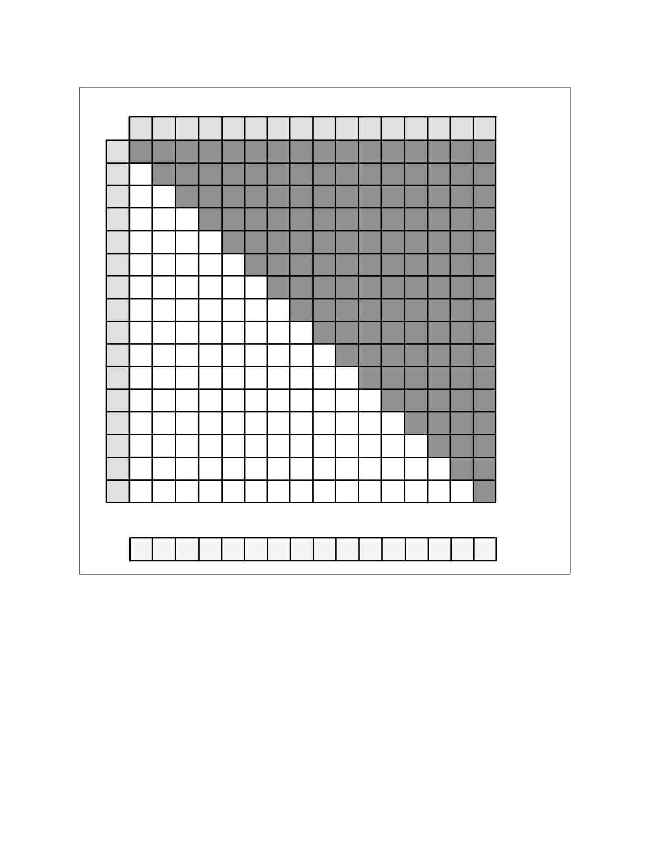
The figure below is an example that shows the execution of a VPCONFLICTD instruction. The input,
ZMM1, contains 16 integers, shown in the light grey boxes. ZMM1 is at the top of the figure, and also
visually transposed along the left-hand side of the figure. The white boxes show the equality comparisons
that the hardware performs between different elements of ZMM1, and the outcome of each comparison
(0 = not equal, 1 = equal). Each comparison output is a single bit in the output of the instruction.
Comparisons that are not performed (i.e., the dark grey boxes) produce a single '0' bit in the output.
Finally, the output register, ZMM0, is shown at the bottom of the figure. Each element is shown as a
decimal representation of the bits above it.
Use VPCONFLICT in different ways to help vectorize loops.
The simplest option is to check for any duplicate indices in a given SIMD register. If there are none, SIMD
instructions can be used to compute all elements simultaneously. If conflicts are present, execute a
scalar loop for that group of elements.
Branching to a scalar version of the loop on any duplicate indices can work well if duplicates are
extremely rare. However, if the chance of getting even one duplicate in a given iteration of the vectorized
loop is large enough, then it is better to use SIMD as much as possible, to exploit as much parallelism as
possible.
18-47
SOFTWARE OPTIMIZATION FOR INTEL® AVX-512 INSTRUCTIONS
ZMM1
… 63 32 31
0 bits
3
10
3
9
4
6
7
0
1
50
2
8
1
3
3
5
ZMM1
3
10
0
3
1
0
9
0
0
0
4
0
0
0
0
6
0
0
0
0
0
7
0
0
0
0
0
0
0
0
0
0
0
0
0
0
1
0
0
0
0
0
0
0
0
50
0
0
0
0
0
0
0
0
0
2
0
0
0
0
0
0
0
0
0
0
8
0
0
0
0
0
0
0
0
0
0
0
1
0
0
0
0
0
0
0
0
1
0
0
0
…
3
1
0
1
0
0
0
0
0
0
0
0
0
0
63
3
1
0
1
0
0
0
0
0
0
0
0
0
0
1
32
31
5
0
0
0
0
0
0
0
0
0
0
0
0
0
0
0
0
bits
… 63 32 31
0 bits
8198
0
6
0
0
0
0
0
8
0
0
0
0
2
0
0
ZMM0
Figure 18-10. VPCONFLICTD Instruction Execution
For loops performing updates to memory locations, such as in the histogram example, minimize store-
load forwarding by merging the updates to each distinct index while the data is in registers, and only
perform a single write to each memory location. Further, the merge can be performed in a parallel
fashion.
18-48
SOFTWARE OPTIMIZATION FOR INTEL® AVX-512 INSTRUCTIONS
ZMM1
… 63 32 31
0 bits
3
10
3
9
4
6
7
0
1
50
2
8
1
3
3
5
Step 1
Step 2
SOM 00014
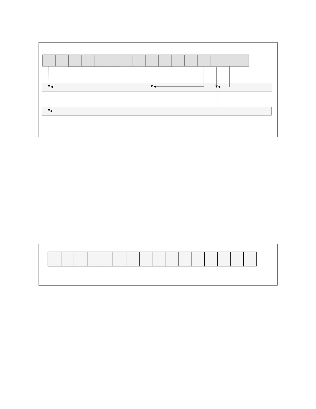
Figure 18-11. VPCONFLICTD Merging Process
The figure above shows the merging process for the example set of indices. While the figure shows only
the indices, it actually merges the values. Most of the indices are unique, and thus require no merging.
Step 1 combines three pairs of indices: two pairs of '3's and one pair of '1's. Step 2 combines the inter-
mediate results for the '3's from step 1, so that there is now a single value for each distinct index. Notice
that in only two steps, the four elements with an index value of 3 are merged, because we performed a
tree reduction; we merged pairs of results or intermediate results at each step.
The merging (combining or reduction) process shown above is done with a set of permute operations.
The initial permute control is generated with a VPLZCNT+VPSUB sequence. VPLZCNT provides the
number of leading zeros for each vector element (i.e., contiguous zeros in the most significant bit posi-
tions). Subtracting the results of VPLZCNT from the number of bits in each vector element, minus one,
provides the bit position of the most significant '1' bit in the result of the VPCONFLICT instruction, or
results in a '-1' for an element if it has no conflicts. In the example above this sequence results in the
following permute control.
13
-1
-2
-1
-1
-1
-1
-1
-3
-1
-1
-1
-1
-1
-1
-1
SOM00015
Figure 18-12. VPCONFLICTD Permute Control
The permute loop for merging matching indices and generating the next set of permute indices repeats
until all values in the permute control become equal to ‘-1’.
The assembly code below shows both the scalar version of a histogram loop, and the vectorized version
with a tree reduction. Speedups are modest because the loop contains little computation; the SIMD
benefit comes almost entirely from vectorizing just the logical AND operation and the increment. SIMD
speedups can be much higher for loops containing more vectorizable computation.
18-49

SOFTWARE OPTIMIZATION FOR INTEL® AVX-512 INSTRUCTIONS
Example 18-19. Scatter Implementation Alternatives
Scalar Code (Unrolled Two Times)
Intel® AVX-512 Code
mov r9d, bins_minus_1
vmovaps zmm4, all_1 // {1, 1, …, 1}
mov ebx, num_inputs
vmovaps zmm5, all_negative_1
mov r10, pInput
vmovaps zmm6, all_31
mov r15, pHistogram
vmovaps zmm7, all_bins_minus_1
xor rax, rax
mov ebx, num_inputs
histogram_loop:
mov r10, pInput
lea ecx, [rax + rax]
mov r15, pHistogram
inc eax
xor rcx, rcx
movsxd rcx, ecx
histogram_loop:
mov esi, [r10+rcx*4]
vpandd zmm3, zmm7, [r10+rcx*4]
and esi, r9d
vpconflictd zmm0, zmm3
mov r8d, [r10+rcx*4+4]
kxnorw k1, k1, k1
movsxd rsi, esi
vmovaps zmm2, zmm4
and r8d, r9d
vpxord zmm1, zmm1, zmm1
movsxd r8, r8d
vpgatherdd zmm1{k1}, [r15+zmm3*4]
inc dword ptr [r15+rsi*4]
vptestmd k1, zmm0, zmm0
inc dword ptr [r15+r8*4]
kortestw k1, k1
cmp eax, ebx
je update
jb histogram_loop
vplzcntd zmm0, zmm0
vpsubd zmm0, zmm6, zmm0
conflict_loop:
vpermd zmm8{k1}{z}, zmm0, zmm2
vpermd zmm0{k1}, zmm0, zmm0
vpaddd zmm2{k1}, zmm2, zmm8
vpcmpned k1, zmm5, zmm0
kortestw k1, k1
jne conflict_loop
update:
vpaddd zmm0, zmm2, zmm1
kxnorw k1, k1, k1
add rcx, 16
vpscatterdd [r15+zmm3*4]{k1}, zmm0
cmp ecx, ebx
jb histogram_loop
Scalar, Baseline, 1x
Speedup: 1.11x (random inputs); 1.34x (input values
identical)
Notice that the end result of the conflict loop (i.e., the resulting vector after all merging is done, ZMM2 in
the above sequence) holds the complete set of partial sums. That is, for each element, the result contains
the value of that element merged with all earlier elements with the same index value. Using the earlier
example values, ZMM2 contains the result shown in Figure 18-13.
18-50

SOFTWARE OPTIMIZATION FOR INTEL® AVX-512 INSTRUCTIONS
4
1
1
1
1
1
1
1
2
1
1
1
1
2
1
1
SOM00016
Figure 18-13. VPCONFLICTD ZMM2 Result
While the above sequence does not take advantage of this, other use cases might.
18.16.2 Sparse Dot Product with VPCONFLICT
A sparse vector may be stored as a pair of arrays: one containing non-zero values, and one containing
the original locations of those values in the vector. Note that the indices are sorted in increasing order.
… 127 64 63
0 bits
1.0
5.0
-2.0
8.0
0.1
3.5
3.1
5.0
A_value
… 63 32 31
0 bits
87
41
32
15
10
4
3
0
A_index
SOM00017
Figure 18-14. Sparse Vector Example
To perform a dot product of two sparse vectors efficiently, we need to find elements with matching
indices; those are the only ones on which we should perform the multiply and accumulation. The scalar
method for doing this is to start at the beginning of the two index arrays, compare those indices, and if
there is a match, do the multiply and accumulate, then advance the indices of both vectors. If there is no
match, we advance the index of the lagging vector.
18-51
SOFTWARE OPTIMIZATION FOR INTEL® AVX-512 INSTRUCTIONS
A_offset = 0; B_offset = 0; sum = 0;
while ((A_offset < A_length) && (B_offset < B_length))
{
if (A_index[A_offset] == B_index[B_offset]) // match
{
sum += A_value[A_offset] * B_value[B_offset];
A_offset++;
B_offset++;
}
else if (A_index[A_offset] < B_index[B_offset])
{
A_offset++;
}
else
{
B_offset++;
}
}
The Intel AVX-512CD instructions provide an efficient way to vectorize this loop. Instead of comparing
one index from each vector at a time, we can compare eight of them. First we combine eight indices from
each vector into a single vector register. Then, the VPCONFLICT instruction compares the indices. We use
the output to create a mask of elements in vector A that have a match, and also to create permute
controls to move the corresponding values of B to the same location, so that we can use a vector FMA
instruction.
Example 18-20 shows the assembly code for both the scalar and vector versions of a single comparison
and FMA. For brevity, the offset updates and looping are omitted.
18-52

SOFTWARE OPTIMIZATION FOR INTEL® AVX-512 INSTRUCTIONS
Example 18-20. Scalar vs. Vector Update Using AVX-512CD
Scalar Code
Intel® AVX-512 Code
mov rdx, A_index
mov rdx, A_index
mov rcx, A_offset
mov rcx, A_offset
mov rax, A_value
mov rax, A_value
mov r12, B_index
mov r12, B_index
mov r13, B_offset
mov r13, B_offset
mov rbx, B_value
mov rbx, B_value
mov r14, all_31s // array of {31, 31, …}
mov r10d, [rdx+rcx*4]
vmovaps zmm2, [r14]
mov r11d, [r12+r13*4]
mov r15, upconvert_control // array of {0, 7, 0, 6, 0, 5,
cmp r10d, r11d
0, 4, 0, 3, 0, 2, 0, 1, 0, 0}
jne skip_fma
vmovaps zmm1, [r15]
vpternlogd zmm0, zmm0, zmm0, 255
// do the fma on a match
movl esi, 21845
movsd xmm5, [rbx+r13*8]
kmovw k1, esi // odd bits set
mulsd xmm5, [rax+rcx*8]
addsd xmm4, xmm5
// read 8 indices for A
skip_fma:
vmovdqu ymm5, [rdx+rcx*4]
// read 8 indices for B, and put
// them in the high part of zmm6
vinserti64x4 zmm6, zmm5, [r12+r13*4], 1
vpconflictd zmm7, zmm6
// extract A vs. B comparisons
vextracti64x4 ymm8, zmm7, 1
// convert comparison results to
// permute control
vplzcntd zmm9, zmm8
vptestmd k2, zmm8, zmm0
vpsubd zmm10, zmm2, zmm9
// upconvert permute controls from
// 32b to 64b, since data is 64b
vpermd zmm11{k1}, zmm1, zmm10
// Move A values to corresponding
// B values, and do FMA
vpermpd zmm12{k2}{z}, zmm11, [rax+rcx*8]
vfmadd231pd zmm4, zmm12, [rbx+r13*8]
Baseline, 1x
Speedup, 4.4x
18.17 INTEL® AVX-512 VECTOR BYTE MANIPULATION INSTRUCTIONS
(VBMI)
Intel® AVX-512 VBMI instructions are a set of 512-bit instructions that are designed to speed up bit
manipulation operations. The following sections describe the new instructions and show simple usage
examples. See the Intel® 64 and IA-32 Architectures Software Developer’s Manual for complete instruction defini-
tions. Processors that provide VBMI1 and VBMI2 are enumerated by the CPUID feature flags
CPUID:(EAX=07H, ECX=0):ECX[bit 01] = 1 and CPUID:(EAX=07H, ECX=0):ECX[bit 06] = 1, respec-
tively.
18-53
SOFTWARE OPTIMIZATION FOR INTEL® AVX-512 INSTRUCTIONS
18.17.1 Permute Packet Bytes Elements Across Lanes (VPERMB)
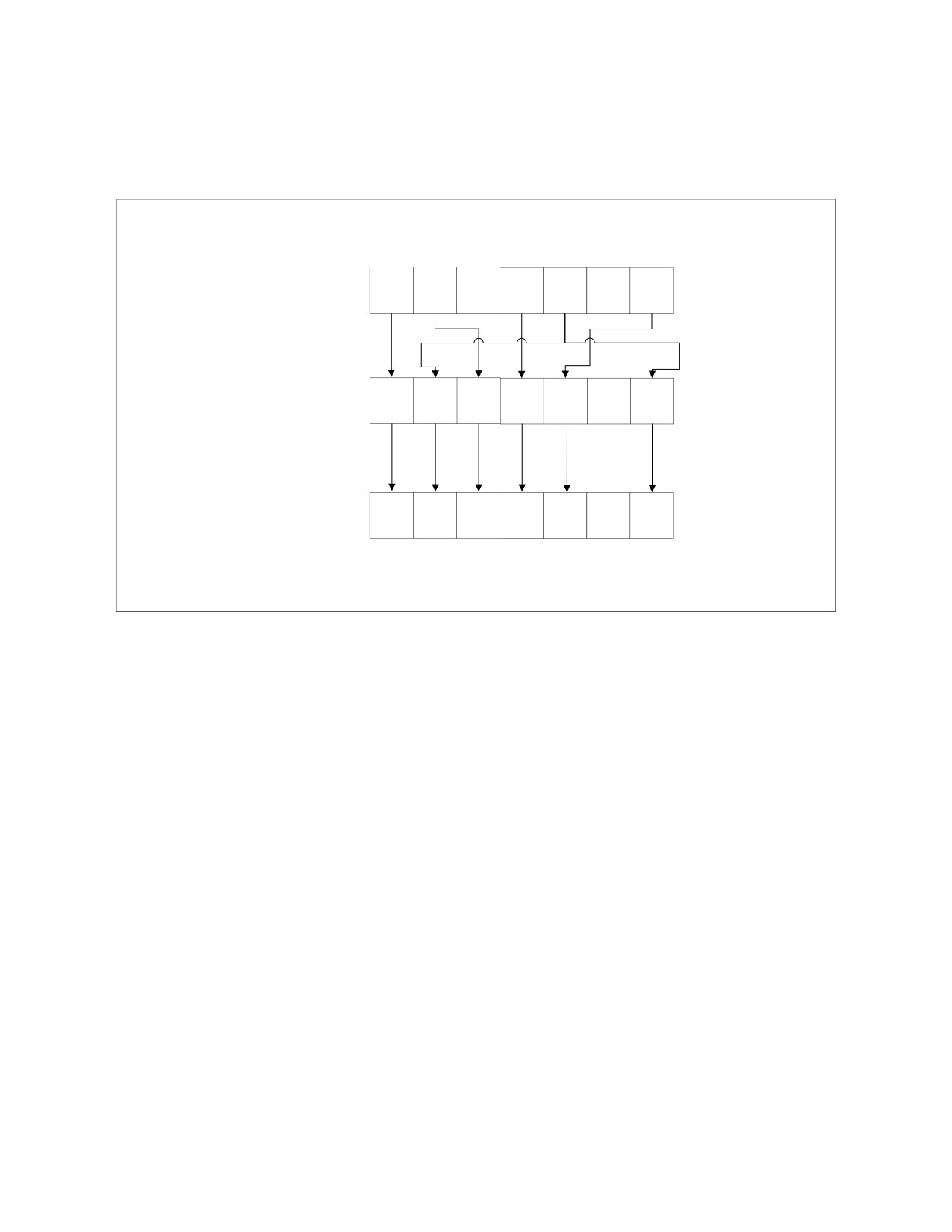
The VPERMB instruction is a single source, any-to-any byte permute instruction. The following figure
shows a VPERMB instruction operation example.
VPERMB zmm0, zmm1, zmm2
zmm2 src2:
A0
A1
A2
A3
A4
A63
zmm1 src1:
0
4
1
3
63
4
zmm0 dst:
A0
A4
A1
A3
A63
A4
SOM00018
Figure 18-15. VPERMB Instruction Operation
VPERMB Operation:
// vpermb zmm Dst {k1}, zmm Src1, zmm Src2
bool zero_masking=false;
unsigned char *Dst, *Src1, *Src2;
for(int i=0;i<64;i++){
if(k1[i]){
Dst[i]= Src2[Src1[i]];
}else{
Dst[i]= zero_masking? 0 : Dst[i];
}
}
The following example shows a 64-byte lookup table implementation.
Scalar code:
void lookup(unsigned char* in_bytes, unsigned char* out_bytes, unsigned char* dictionary_bytes, int numOfElements){
for(int i = 0; i < numOfElements; i++) {
out_bytes[i] = dictionary_bytes[in_bytes[i] & 63];
}
}
18-54
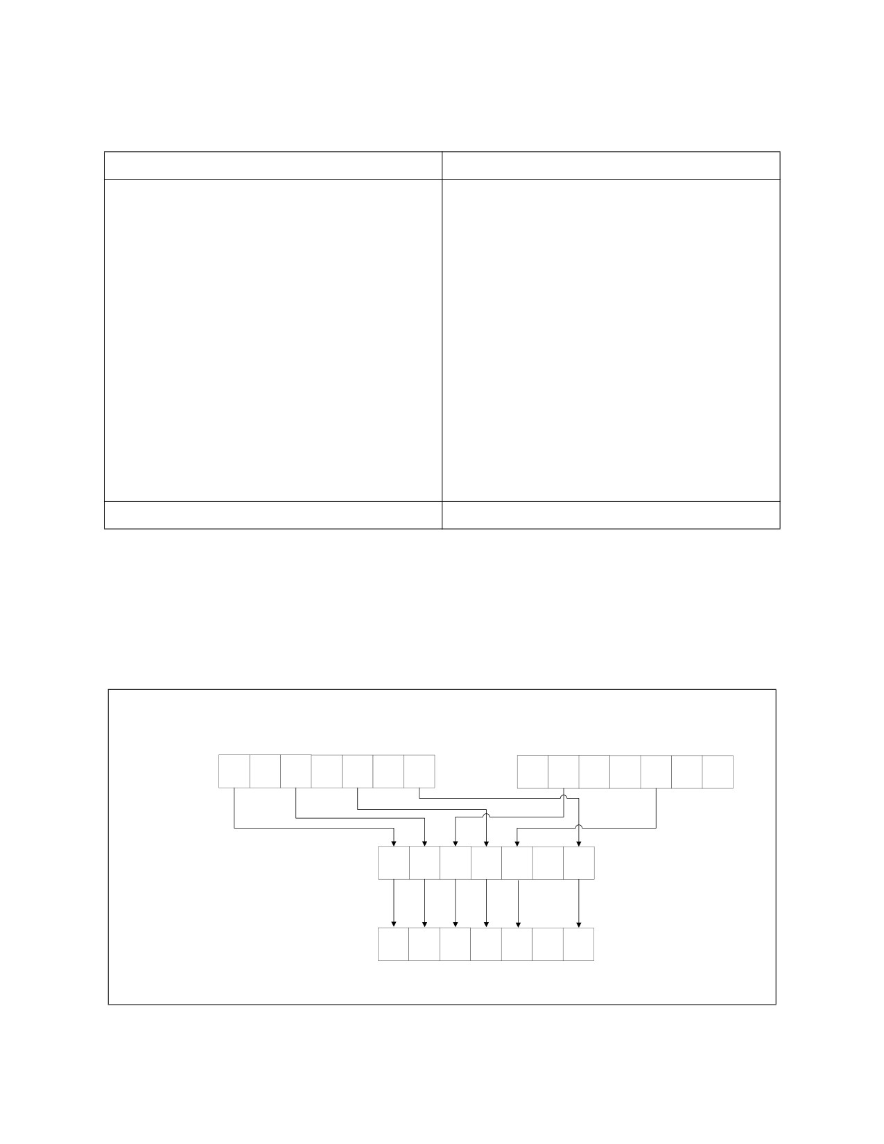
SOFTWARE OPTIMIZATION FOR INTEL® AVX-512 INSTRUCTIONS
Example 18-21. Improvement with VPERMB Implementation
Alternative 1: Vector Implementation Without VBMI
Alternative 2: VPERMB Implementation
mov rsi, dictionary_bytes
mov rsi, dictionary_bytes
mov r11, in_bytes
mov r11, in_bytes
mov rax, out_bytes
mov rax, out_bytes
mov r9d, numOfElements
mov r9d, numOfElements
xor r8, r8
xor r8, r8
vpmovzxbw zmm3, [rsi]
vmovdqu32 zmm2, [rsi]
vpmovzxbw zmm4, [rsi+32]
loop:
loop:
vmovdqu32 zmm1, [r11+r8*1]
vpmovzxbw zmm1, [r11+r8*1]
vpermb zmm1, zmm1, zmm2
vpmovzxbw zmm2, [r11+r8*1+32]
vmovdqu32 [rax+r8*1], zmm1
vpermi2w zmm1, zmm3, zmm4
add r8, 64
vpermi2w zmm2, zmm3, zmm4
cmp r8, r9
vpmovwb [rax+r8*1], zmm1
jl loop
vpmovwb [rax+r8*1+32], zmm2
add r8, 64
cmp r8, r9
jl loop
Base Measurement: 1x
Speedup: 6.5x
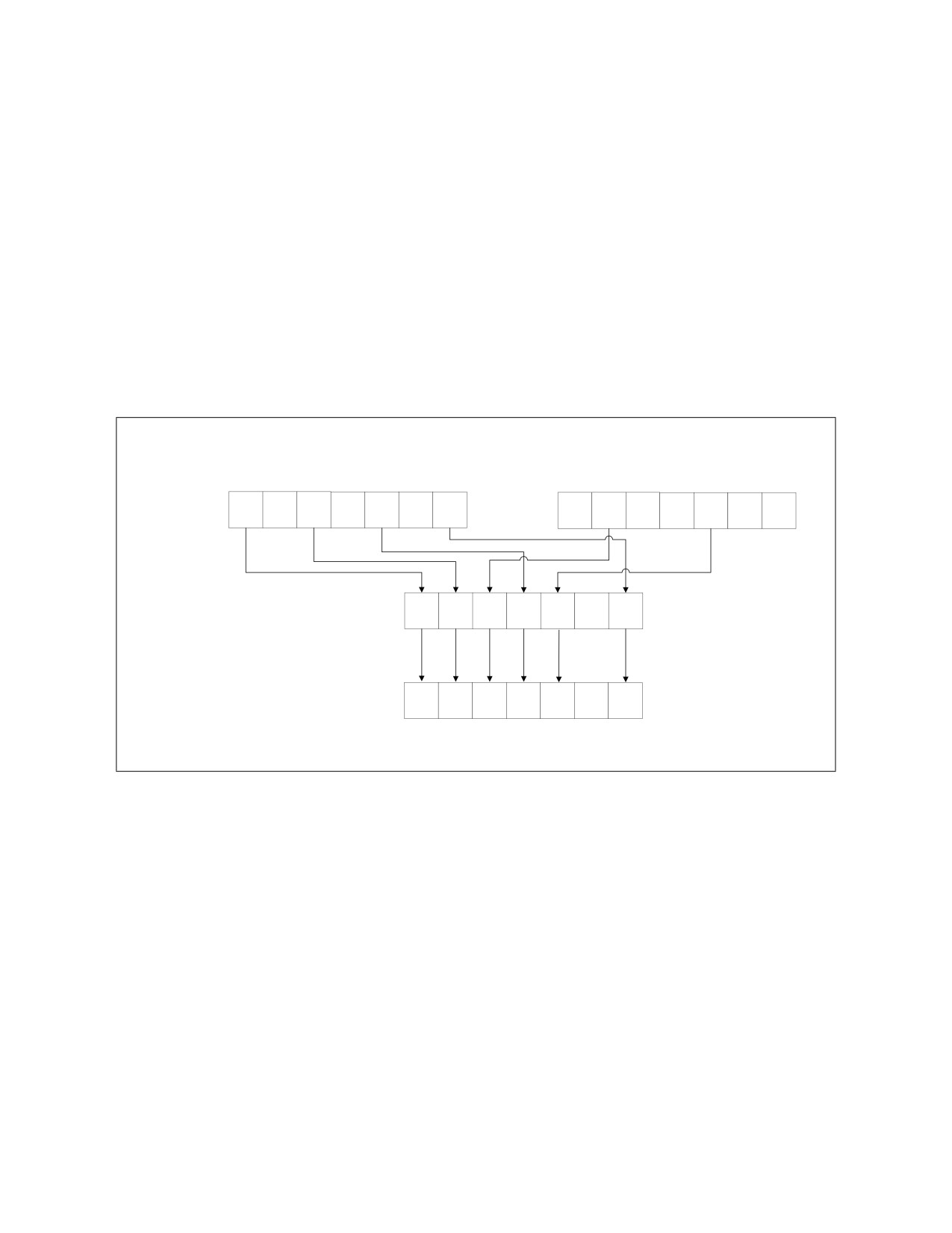
18.17.2 Two-Source Byte Permute Across Lanes (VPERMI2B, VPERMT2B)
The VPERMI2B and VPERMT2B instructions are two-source byte, permute instructions. The destination is
also an operation source; in VPERMI2B the destination is the operation index, and in VPERMT2B the
destination is one of the data sources.
The following figure shows a VPERMI2B instruction operation example.
VPERMI2B zmm0, zmm1, zmm2
Index:
0
1
2
3
4
…
63
64
65
66
67
68
…
127
zmm1 src1:
A0
A1
A2
A3
A4
A63
zmm2 src2:
B0
B1
B2
B3
B4
B63
zmm0 (index and source):
0
2
65
4
68
63
zmm0 (dst):
A0
A2
B1
A4
B4
A63
SOM00019
Figure 18-16. VPERMI2B Instruction Operation
18-55
SOFTWARE OPTIMIZATION FOR INTEL® AVX-512 INSTRUCTIONS
VPERMI2B Operation:
/// vpermi2b Dst{k1}, Src1, Src2
bool zero_masking=false;
unsigned char *Dst, *Src1, *Src2;
for(int i=0;i<64;i++){
if(k1[i]){
Dst[i]= Dst [i]>63 ? Src1[Dst [i] & 63] : Src2[Dst [i] & 63] ;
}else{
Dst[i]= zero_masking? 0 : Dst[i];
}
}
The following figure shows a VPERMT2B instruction operation example.
VPERMT2B zmm0, zmm1, zmm2
Index:
0
1
2
3
4
…
63
64
65
66
67
68
…
127
zmm0
zmm1 src1:
A0
A1
A2
A3
A4
A63
B0
B1
B2
B3
B4
B63
data source:
zmm2 src2:
0
2
65
4
68
63
zmm0 (dst):
A0
A2
B1
A4
B4
A63
SOM00020
Figure 18-17. VPERMT2B Instruction Operation
VPERMT2B Operation:
// vpermt2b Dst{k1}, Src1, Src2
bool zero_masking=false;
unsigned char *Dst, *Src1, * Src2;
data2= copy(Dst);
for(int i=0;i<64;i++){
if(k1[i]){
Dst[i]= Src2[i]>63 ? Src1[Src2 [i] & 63] : Dst[Src2[i] & 63] ;
}else{
Dst[i]= zero_masking? 0 : Dst[i];
}
}
18-56

SOFTWARE OPTIMIZATION FOR INTEL® AVX-512 INSTRUCTIONS
The following example shows a 128-byte lookup table implementation.
C Code:
void lookup(unsigned char* in_bytes, unsigned char* out_bytes, unsigned char* dictionary_bytes, int numOfElements){
for(int i = 0; i < numOfElements; i++) {
out_bytes[i] = dictionary_bytes[in_bytes[i] & 127];
}
}
Example 18-22. Improvement with VPERMI2B Implementation
Alternative 1: Vector Implementation Without VBMI
Alternative 2: VPERMI2B Implementation
//get data sent to function
mov rsi, dictionary_bytes
mov rsi, dictionary_bytes
mov r11, in_bytes
mov r11, in_bytes
mov rax, out_bytes
mov rax, out_bytes
mov r9d, numOfElements
mov r9d, numOfElements
xor r8, r8
xor r8, r8
vmovdqu32 zmm2, [rsi]
//Reorganize dictionary
vmovdqu32 zmm3, [rsi+64]
vpmovzxbw zmm10, [rsi]
loop:
vpmovzxbw zmm15, [rsi+64]
vmovdqu32 zmm1, [r11+r8*1]
vpsllw zmm15, zmm15, 8
vpermi2b zmm1, zmm2, zmm3
vpord zmm10, zmm15, zmm10
vmovdqu32 [rax+r8*1], zmm1
vpmovzxbw zmm11, [rsi+32]
add r8, 64
vpmovzxbw zmm15, [rsi+96]
cmp r8, r9
vpsllw zmm15, zmm15, 8
jl loop
vpord zmm11, zmm15, zmm11
//initialize constants
mov r10, 0x00400040
vpbroadcastw zmm12, r10d
mov r10, 0
vpbroadcastd zmm13, r10d
mov r10, 0x00ff00ff
vpbroadcastd zmm14, r10d
//start iterations
loop:
vpmovzxbw zmm1, [r11+r8*1]
vpandd zmm2, zmm1, zmm12
vpcmpw k1, zmm2, zmm13, 4
vpermi2w zmm1, zmm10, zmm11
vpsrlw zmm1{k1}, zmm1, 8
vpandd zmm1, zmm1, zmm14
vpmovwb [rax+r8*1], zmm1
add r8, 32
cmp r8, r9
jl loop
Base Measurement: 1x
Speedup: 5.3x
18-57
SOFTWARE OPTIMIZATION FOR INTEL® AVX-512 INSTRUCTIONS
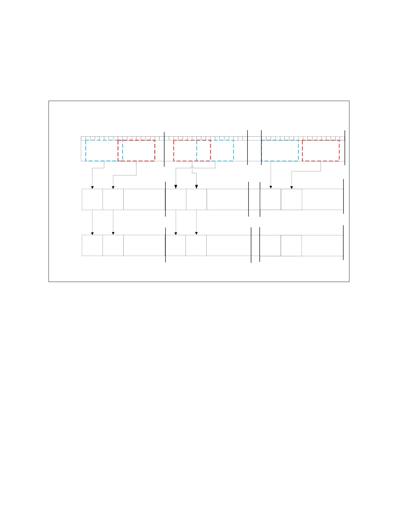
18.17.3 Select Packed Unaligned Bytes from Quadword Sources (VPMULTISHIFTQB)
The VPMULTISHIFTQB instruction selects eight unaligned bytes from each input qword element of the
second source operand and writes eight assembled bytes for each qword element in the destination
operand.
The following figure shows a VPMULTISHIFTQB instruction operation example.
VPMULTISHIFTQB zmm0, zmm1, zmm2
qword2
qword8
qword1
0
1
2
3
4
5
6
7
8
9
10
11
12
13
14
15
63
0
1
2
3
4
5
6
7
8
9
10
11
12
13
14
15
63
0
1
2
3
4
5
6
7
8
9
10
11
12
13
14
15
63
zmm2 src2:
A1-8
A8-15
B2-9
B7-14
H0-7
H9-16
zmm1 src1:
1
8
7
2
0
9
Index: 0
Index: 1
Index: 8
Index: 9
zmm0 dst:
A1-8
A8-15
B2-9
B7-14
H0-7
H9-16
SOM00022
Figure 18-18. VPMULTISHIFTQB Instruction Operation
VPMULTISHIFTQB Operation:
// vpmultishiftqb Dst{k1},Src1,Src2
bool zero_masking=false;
unsigned char *Dst, * Src1;
unsigned __int64 *Src2;
bit * k1;
for(int i=0;i<8;i++){
for(int j=0;j<8;j++){
if(k1[i*8 +j]){
Dst[i*8 +j]= (src2[i]>> Src1[i*8 +j]) &0xFF ;
}else{
Dst[i*8 +j]= zero_masking? 0 : Dst[i*8 +j];
}
}
}
18-58

SOFTWARE OPTIMIZATION FOR INTEL® AVX-512 INSTRUCTIONS
The following example converts a 5-bit unsigned integer array to a 1-byte unsigned integer array.
C code:
void decompress (unsigned char* compressedData, unsigned char* decompressedData, int numOfElements){
for(int i = 0; i < numOfElements; i += 8){
unsigned __int64 * data = (unsigned __int64 * )compressedData;
decompressedData[i+0] = * data & 0x1f;
decompressedData[i+1] = (*data >> 5 ) & 0x1f;
decompressedData[i+2] = (*data >> 10 ) & 0x1f;
decompressedData[i+3] = (*data >> 15 ) & 0x1f;
decompressedData[i+4] = (*data >> 20 ) & 0x1f;
decompressedData[i+5] = (*data >> 25 ) & 0x1f;
decompressedData[i+6] = (*data >> 30 ) & 0x1f;
decompressedData[i+7] = (*data >> 35 ) & 0x1f;
compressedData += 5;
}
}
Example 18-23. Improvement with VPMULTISHIFTQB Implementation
Alternative 1: Vector Implementation Without VBMI
Alternative 2: VPMULTISHIFTQB Implementation
mov rdx, compressedData
//constants :
mov r9, decompressedData
__declspec (align(64)) const unsigned __int8
mov eax, numOfElements
permute_ctrl[64] = {
shr eax,3
0, 1, 2, 3, 4, 0, 0, 0
xor rsi, rsi
5, 6, 7, 8, 9, 0, 0, 0
loop:
10, 11, 12, 13, 14, 0, 0, 0
mov rcx, qword ptr [rdx]
15, 16, 17, 18, 19, 0, 0, 0
mov r10, rcx
20, 21, 22, 23, 24, 0, 0, 0
and r10, 0x1f
25, 26, 27, 28, 29, 0, 0, 0
mov r11, rcx
30, 31, 32, 33, 34, 0, 0, 0
mov byte ptr [r9+rsi*8], r10b
35, 36, 37, 38, 39, 0, 0, 0
mov r10, rcx
};
shr r10, 0xa
__declspec (align(64)) const unsigned __int8
add rdx, 0x5
multishift_ctrl[64] = {
and r10, 0x1f
0, 5, 10, 15, 20, 25, 30, 35
mov byte ptr [r9+rsi*8+0x2], r10b
0, 5, 10, 15, 20, 25, 30, 35
mov r10, rcx
0, 5, 10, 15, 20, 25, 30, 35
shr r10, 0xf
0, 5, 10, 15, 20, 25, 30, 35
and r10, 0x1f
0, 5, 10, 15, 20, 25, 30, 35
mov byte ptr [r9+rsi*8+0x3], r10b
0, 5, 10, 15, 20, 25, 30, 35
mov r10, rcx
0, 5, 10, 15, 20, 25, 30, 35
shr r10, 0x14
0, 5, 10, 15, 20, 25, 30, 35
and r10, 0x1f
};
mov byte ptr [r9+rsi*8+0x4], r10b
//asm:
mov r10, rcx
mov rsi, compressedData
shr r10, 0x19
mov rdi, decompressedData
and r10, 0x1f
mov r8d, numOfElements
mov byte ptr [r9+rsi*8+0x5], r10b
lea r8, [rdi+r8]
mov r10, rcx
mov r9, 0x1F1F1F1F
shr r11, 0x5
vpbroadcastd zmm12, r9d
shr r10, 0x1e
vmovdqu32 zmm10, permute_ctrl
vmovdqu32 zmm11, multishift_ctrl
18-59

SOFTWARE OPTIMIZATION FOR INTEL® AVX-512 INSTRUCTIONS
Example 18-23. Improvement with VPMULTISHIFTQB Implementation (Contd.)
and r11, 0x1f
loop:
shr rcx, 0x23
vmovdqu32 zmm1, [rsi]
and r10, 0x1f
vpermb zmm2, zmm10, zmm1
and rcx, 0x1f
vpmultishiftqb zmm2, zmm11, zmm2
mov byte ptr [r9+rsi*8+0x1], r11b
vpandq zmm2, zmm12, zmm2
mov byte ptr [r9+rsi*8+0x6], r10b
vmovdqu32 [rdi], zmm2
mov byte ptr [r9+rsi*8+0x7], cl
add rdi, 64
inc rsi
add rsi, 40
cmp rsi, rax
cmp rdi, r8
jb loop
jl loop
Base Measurement: 1x
Speedup: 26x
18.18 FMA LATENCY
When executing in 512-bit register port scheme, Port 0 FMA has a latency of 4 cycles, and Port 5 FMA has
a latency of 6 cycles. Bypass can have a -2 (fast bypass) to +1 cycle delay. Therefore, instructions that
execute on the Skylake microarchitecture FMA have a latency of 4-7 cycles.
The instructions are divided into the following two groups.
• Group A Instructions: vadd*; vfmadd*; vfnmsub*; vfnmadd*; vfnmsub*; vmax*; vmin*; vmul*;
vscalef*; vsub*; vcvt*; vgetexp*; vfixupimm*; vrange*; vgetmant*; vreduce*; vcmp*, vcomi*,
vdpp*, vhadd*, vhsub*, vrndscale*, vround*
• Group B Instructions: vpmaddubsw; vpmaddwd; vpmuldq; vpmulhrsw; vpmulhuw; vpmulhw;
vpmullw; vpmuludq
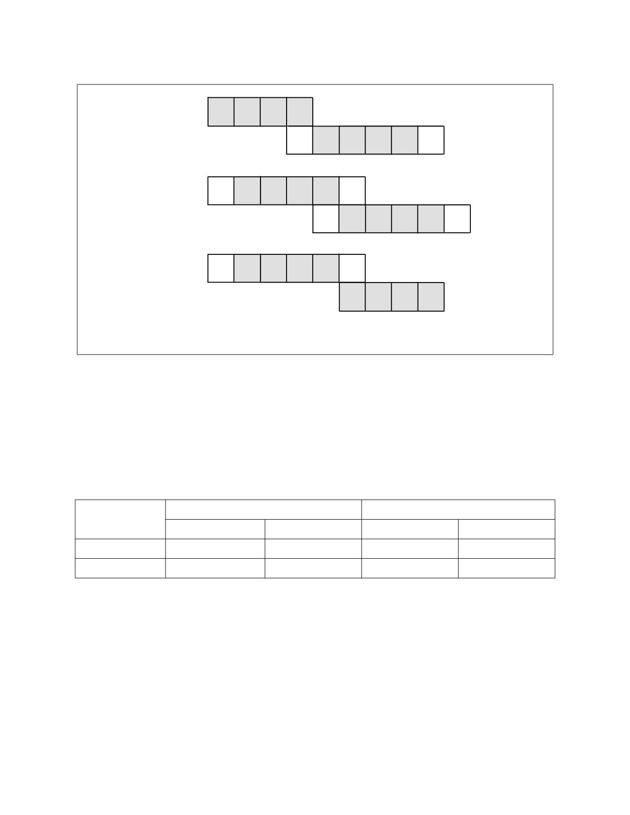
The FMA unit supports fast bypass when all instruction sources come from the FMA unit. In this case
Group A has a latency of 4 cycles for both ports 0 and 5, and Group B has a latency of 5 cycles for both
ports 0 and 5.
The figure below explains fast bypass when all sources come from the FMA unit.
18-60
SOFTWARE OPTIMIZATION FOR INTEL® AVX-512 INSTRUCTIONS
FMA port0
1
2
3
4
FMA port5
1
2
3
4
5
6
FMA port5
1
2
3
4
5
6
FMA port5
1
2
3
4
5
6
FMA port5
1
2
3
4
5
6
FMA port0
1
2
3
4
SOM00021
Figure 18-19. Fast Bypass When All Sources Come from FMA Unit
The grey boxes represent compute cycles. The white boxes represent data transfer for the port5 FMA
unit.
If fast bypass is not used, that is, when not all sources come from the FMA unit, group A instructions have
a latency of 4 cycles on Port0 and 6 cycles on port5, while group B instructions have an additional cycle
and hence have a latency of 5 cycles on Port0 and 7 cycles on port5.
The following table summarizes the FMA unit latency for the various options.
Table 18-7. FMA Unit Latency
Fast Bypass (FMA Data Reuse)
No Fast Bypass (No FMA Data Reuse)
Instruction Group
Port 0
Port 5
Port 0
Port 5
Group A
4
4
4
6
Group B
5
5
5
7
18-61
SOFTWARE OPTIMIZATION FOR INTEL® AVX-512 INSTRUCTIONS
18.19 MIXING INTEL® AVX OR INTEL® AVX-512 EXTENSIONS WITH INTEL®
STREAMING SIMD EXTENSIONS (INTEL® SSE) CODE
There are two main instruction groups that affect the processor states:
• Group A: Instruction types that either set bits 128-511 of vector registers 0-15 to zero, or do not
modify them at all.
— Intel SSE instructions.
— 128-bit Intel AVX instructions, 128-bit Intel AVX-512 instructions.
— 256-bit (ymm16-ymm31) Intel AVX-512 instructions.
— 512-bit (zmm16-zmm31) Intel AVX-512 instructions.
— AVX-512 instructions that write to mask registers k0-k7.
— GPR instructions.
• Group B: Instructions types that modify bits 128-511 of vector registers 0-15.
— 256-bit (ymm0-ymm15) Intel AVX instructions, Intel AVX-512 instructions.
— 512-bit (zmm0-zmm15) Intel AVX-512 instructions.
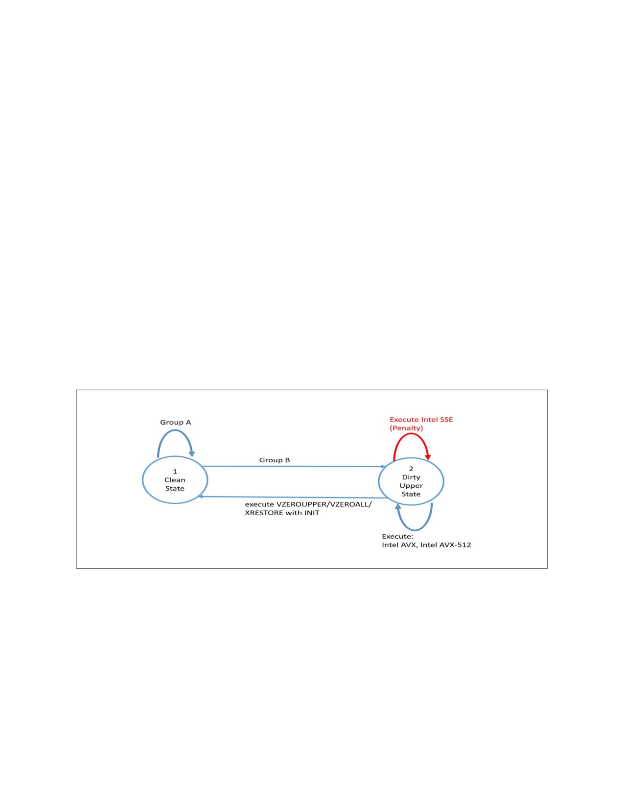
The following figure illustrates Skylake Server microarchitecture's model for mixing Intel AVX instruc-
tions or Intel AVX-512 instructions with Intel SSE instructions.
The implementation is similar to Skylake client microarchitecture, where every Intel SSE instruction
executed in Dirty Upper State (2) needs to preserve bits 128-511 of the destination register, and there-
fore the operation has an additional dependency on the destination register and a blend operation with
bits 128-511.
Figure 18-20. Mixing Intel AVX Instructions or Intel AVX-512 Instructions with Intel SSE Instructions
Recommendations:
• When mixing group B instructions with Intel SSE instructions, or suspecting that such a mixture
might occur, use the VZEROUPPER instruction whenever a transition is expected.
• Add VZEROUPPER after group B instructions were executed and before any function call that might
lead to an Intel SSE instruction execution.
• Add VZEROUPPER at the end of any function that uses group B instructions.
• Add VZEROUPPER before thread creation if not already in a clean state so that the thread does not
inherit a Dirty Upper State.
18-62

SOFTWARE OPTIMIZATION FOR INTEL® AVX-512 INSTRUCTIONS
18.20 MIXING ZMM VECTOR CODE WITH XMM/YMM
Skylake microarchitecture has two port schemes, one for using 256-bit or less registers, and another for
using 512-bit registers.
When using registers up to or including 256 bits, FMA operations dispatch to ports 0 and 1 and SIMD
operations dispatch to ports 0, 1 and 5. When using 512-bit register operations, both FMA and SIMD
operations dispatch to ports 0 and 5.
The maximum register width in the reservation station (RS) determines the 256 or 512 port scheme.
Notice that when using AVX-512 encoded instructions with YMM registers, the instructions are considered
to be 256-bit wide.
The result of the 512-bit port scheme is that XMM or YMM code dispatches to 2 ports (0 and 5) instead of
3 ports (0, 1, and 5) and may have lower throughput and longer latency compared to the 256-bit port
scheme.
Example 18-24. 256-bit Code vs. 256-bit Code Mixed with 512-bit Code
256-bit Code Only
256-bit Code Mixed with 512-bit Code
Loop:
Loop:
vpbroadcastd
ymm0, dword ptr [rsp]
vpbroadcastd
zmm0, dword ptr [rsp]
vfmadd213ps
ymm7, ymm7, ymm7
vfmadd213ps
ymm7, ymm7, ymm7
vfmadd213ps
ymm8, ymm8, ymm8
vfmadd213ps
ymm8, ymm8, ymm8
vfmadd213ps
ymm9, ymm9, ymm9
vfmadd213ps
ymm9, ymm9, ymm9
vfmadd213ps
ymm10, ymm10, ymm10
vfmadd213ps
ymm10, ymm10, ymm10
vfmadd213ps
ymm11, ymm11, ymm11
vfmadd213ps
ymm11, ymm11, ymm11
vfmadd213ps
ymm12, ymm12, ymm12
vfmadd213ps
ymm12, ymm12, ymm12
vfmadd213ps
ymm13, ymm13, ymm13
vfmadd213ps
ymm13, ymm13, ymm13
vfmadd213ps
ymm14, ymm14, ymm14
vfmadd213ps
ymm14, ymm14, ymm14
vfmadd213ps
ymm15, ymm15, ymm15
vfmadd213ps
ymm15, ymm15, ymm15
vfmadd213ps
ymm16, ymm16, ymm16
vfmadd213ps
ymm16, ymm16, ymm16
vfmadd213ps
ymm17, ymm17, ymm17
vfmadd213ps
ymm17, ymm17, ymm17
vfmadd213ps
ymm18, ymm18, ymm18
vfmadd213ps
ymm18, ymm18, ymm18
vpermd
ymm1, ymm1, ymm1
vpermd
ymm1, ymm1, ymm1
vpermd
ymm2, ymm2, ymm2
vpermd
ymm2, ymm2, ymm2
vpermd
ymm3, ymm3, ymm3
vpermd
ymm3, ymm3, ymm3
vpermd
ymm4, ymm4, ymm4
vpermd
ymm4, ymm4, ymm4
vpermd
ymm5, ymm5, ymm5
vpermd
ymm5, ymm5, ymm5
vpermd
ymm6, ymm6, ymm6
vpermd
ymm6, ymm6, ymm6
dec rdx
dec rdx
jnle Loop
jnle Loop
Baseline 1x
Slowdown: 1.3x
In the 256-bit code only example, the FMAs are dispatched to ports 0 and 1, and permd is dispatched to
port 5 as the broadcast instruction is 256 bits wide. In the 256-bit and 512-bit mixed code example, the
broadcast is 512 bits wide; therefore, the processor uses the 512-bit port scheme where the FMAs
dispatch to ports 0 and 5 and permd to port 5, thus increasing the pressure on port 5.
18.21 SERVERS WITH A SINGLE FMA UNIT
Some processors based on Skylake microarchitecture have two Intel AVX-512 FMA units, on ports 0 and
5, while other processors based on Skylake microarchitecture have a single Intel AVX-512 FMA unit,
which is located on port 0.
18-63

SOFTWARE OPTIMIZATION FOR INTEL® AVX-512 INSTRUCTIONS
Code that is optimized to run on a processor with two FMA units might not be optimal when run on a
processor with one FMA unit.
The following example code shows how to detect whether a system has one or two Intel AVX-512 FMA
units. It includes the following:
• An Intel AVX-512 warmup.
• A function that executes only FMA instructions.
• A function that executes both FMA and shuffle instructions.
• Code that, based on the results of these two tests, identifies whether the processor has one or two
FMA units.
Notice that each test is executed three times to improve test accuracy.
In order to reduce the program overhead, it is highly recommended not to execute this test in every func-
tion call, but as part of installation, or once at startup.
The differentiation between the two processors is based on the ratio between the two throughput tests.
Processors with two FMA units are able to run the FMA-only test twice as fast as the FMA and shuffle test.
However, a processor with one FMA unit will run both tests at the same speed.
Example 18-25. Identifying One or Two FMA Units in a Processor Based on Skylake Microarchitecture
#include <string.h>
#include <stdlib.h>
#include <immintrin.h>
#include <stdio.h>
#include <stdint.h>
static uint64_t rdtsc(void) {
unsigned int ax, dx;
__asm__ __volatile__ ("rdtsc" : "=a"(ax), "=d"(dx));
return ((((uint64_t)dx) << 32) | ax);
}
uint64_t fma_shuffle_tpt(uint64_t loop_cnt){
uint64_t loops = loop_cnt;
__declspec(align(64)) double one_vec[8] = {1, 1, 1, 1,1, 1, 1, 1};
__declspec(align(64)) int shuf_vec[16] = {0, 1, 2, 3,4, 5, 6, 7,8, 9, 10, 11,12, 13, 14, 15};
__asm
{
vmovups zmm0, [one_vec]
vmovups zmm1, [one_vec]
vmovups zmm2, [one_vec]
18-64

SOFTWARE OPTIMIZATION FOR INTEL® AVX-512 INSTRUCTIONS
Example 18-25. Identifying One or Two FMA Units in a Processor Based on Skylake Microarchitecture (Contd.)
vmovups zmm3, [one_vec]
vmovups zmm4, [one_vec]
vmovups zmm5, [one_vec]
vmovups zmm6, [one_vec]
vmovups zmm7, [one_vec]
vmovups zmm8, [one_vec]
vmovups zmm9, [one_vec]
vmovups zmm10, [one_vec]
vmovups zmm11, [one_vec]
vmovups zmm12, [shuf_vec]
vmovups zmm13, [shuf_vec]
vmovups zmm14, [shuf_vec]
vmovups zmm15, [shuf_vec]
vmovups zmm16, [shuf_vec]
vmovups zmm17, [shuf_vec]
vmovups zmm18, [shuf_vec]
vmovups zmm19, [shuf_vec]
vmovups zmm20, [shuf_vec]
vmovups zmm21, [shuf_vec]
vmovups zmm22, [shuf_vec]
vmovups zmm23, [shuf_vec]
vmovups zmm30, [shuf_vec]
mov rdx, loops
loop1:
vfmadd231pd zmm0, zmm0, zmm0
vfmadd231pd zmm1, zmm1, zmm1
vfmadd231pd zmm2, zmm2, zmm2
vfmadd231pd zmm3, zmm3, zmm3
vfmadd231pd zmm4, zmm4, zmm4
vfmadd231pd zmm5, zmm5, zmm5
vfmadd231pd zmm6, zmm6, zmm6
vfmadd231pd zmm7, zmm7, zmm7
vfmadd231pd zmm8, zmm8, zmm8
vfmadd231pd zmm9, zmm9, zmm9
vfmadd231pd zmm10, zmm10, zmm10
vfmadd231pd zmm11, zmm11, zmm11
vpermd zmm12, zmm30, zmm30
vpermd zmm13, zmm30, zmm30
vpermd zmm14, zmm30, zmm30
vpermd zmm15, zmm30, zmm30
vpermd zmm16, zmm30, zmm30
vpermd zmm17, zmm30, zmm30
vpermd zmm18, zmm30, zmm30
vpermd zmm19, zmm30, zmm30
vpermd zmm20, zmm30, zmm30
vpermd zmm21, zmm30, zmm30
vpermd zmm22, zmm30, zmm30
vpermd zmm23, zmm30, zmm30
dec rdx
jg loop1
}
}
18-65

SOFTWARE OPTIMIZATION FOR INTEL® AVX-512 INSTRUCTIONS
Example 18-25. Identifying One or Two FMA Units in a Processor Based on Skylake Microarchitecture (Contd.)
uint64_t fma_only_tpt(int loop_cnt){
uint64_t loops = loop_cnt;
__declspec(align(64)) double one_vec[8] = {1, 1, 1, 1,1, 1, 1, 1};
__asm
{
vmovups zmm0, [one_vec]
vmovups zmm1, [one_vec]
vmovups zmm2, [one_vec]
vmovups zmm3, [one_vec]
vmovups zmm4, [one_vec]
vmovups zmm5, [one_vec]
vmovups zmm6, [one_vec]
vmovups zmm7, [one_vec]
vmovups zmm8, [one_vec]
vmovups zmm9, [one_vec]
vmovups zmm10, [one_vec]
vmovups zmm11, [one_vec]
mov rdx, loops
loop1:
vfmadd231pd zmm0, zmm0, zmm0
vfmadd231pd zmm1, zmm1, zmm1
vfmadd231pd zmm2, zmm2, zmm2
vfmadd231pd zmm3, zmm3, zmm3
vfmadd231pd zmm4, zmm4, zmm4
vfmadd231pd zmm5, zmm5, zmm5
vfmadd231pd zmm6, zmm6, zmm6
vfmadd231pd zmm7, zmm7, zmm7
vfmadd231pd zmm8, zmm8, zmm8
vfmadd231pd zmm9, zmm9, zmm9
vfmadd231pd zmm10, zmm10, zmm10
vfmadd231pd zmm11, zmm11, zmm11
dec rdx
jg loop1
}
}
int main()
{
int i;
uint64_t fma_shuf_tpt_test[3];
uint64_t fma_shuf_tpt_test_min;
uint64_t fma_only_tpt_test[3];
uint64_t fma_only_tpt_test_min;
uint64_t start = 0;
uint64_t number_of_fma_units_per_core = 2;
18-66

SOFTWARE OPTIMIZATION FOR INTEL® AVX-512 INSTRUCTIONS
Example 18-25. Identifying One or Two FMA Units in a Processor Based on Skylake Microarchitecture (Contd.)
/*********************************************************/
/* Step 1: Warmup */
/*********************************************************/
fma_only_tpt(100000);
/*********************************************************/
/* Step 2: Execute FMA and Shuffle TPT Test */
/*********************************************************/
for(i = 0; i < 3; i++){
start = rdtsc();
fma_shuffle_tpt(1000);
fma_shuf_tpt_test[i] = rdtsc() - start;
}
/*********************************************************/
/* Step 3: Execute FMA only TPT Test */
/*********************************************************/
for(i = 0; i < 3; i++){
start = rdtsc();
fma_only_tpt(1000);
fma_only_tpt_test[i] = rdtsc() - start;
}
/*********************************************************/
/* Step 4: Decide if 1 FMA server or 2 FMA server */
/*********************************************************/
fma_shuf_tpt_test_min = fma_shuf_tpt_test[0];
fma_only_tpt_test_min = fma_only_tpt_test[0];
for(i = 1; i < 3; i++){
if ((int)fma_shuf_tpt_test[i] < (int)fma_shuf_tpt_test_min) fma_shuf_tpt_test_min = fma_shuf_tpt_test[i];
if ((int)fma_only_tpt_test[i] < (int)fma_only_tpt_test_min) fma_only_tpt_test_min = fma_only_tpt_test[i];
}
if(((double)fma_shuf_tpt_test_min/(double)fma_only_tpt_test_min) < 1.5){
number_of_fma_units_per_core = 1;
}
printf("%d FMA server\n", number_of_fma_units_per_core);
return 0;
}
18-67

SOFTWARE OPTIMIZATION FOR INTEL® AVX-512 INSTRUCTIONS
18.22 GATHER/SCATTER TO SHUFFLE (G2S/STS)
18.22.1 Gather to Shuffle in Strided Loads
In cases where there is data locality between gathered elements in memory, performance can be
improved by replacing the gather instruction with a software sequence.
This section discusses the very common strided load pattern. Strided loads are sets of loads where the
offset in memory between two consecutive loads is constant.
The following examples show three different code variations performing an Array of Structures (AOS) to
Structure of Arrays (SOA) transformation. The code separates the real and imaginary elements in a
complex array into two separate arrays.
Consider the following C code:
for(int i=0;i<len;i++){
Real_buffer[i] = Complex_buffer[i].real;
Imaginary_buffer[i] = Complex_buffer[i].imag;
}
Example 18-26. Gather to Shuffle in Strided Loads Example
Alternative 1: Intel® AVX-512 vpgatherdd
Alternative 2: G2S Using Intel® AVX-512 vpermi2d
loop:
vmovups zmm4, [rdx+r9*8]
vpcmpeqb k1, xmm0, xmm0
vmovups zmm0, [rdx+r9*8+0x40]
vpcmpeqb k2, xmm0, xmm0
vmovups zmm5, [rdx+r9*8+0x80]
movsxd rdx, edx
vmovups zmm1, [rdx+r9*8+0xc0]
movsxd rdi, esi
vmovaps zmm2, zmm7
inc esi
vmovaps zmm3, zmm7
shl rdi, 0x7
vpermi2d zmm2, zmm4, zmm0
vpxord zmm2, zmm2, zmm2
vpermt2d zmm4, zmm6, zmm0
lea rax, [r8+rdx*8]
vpermi2d zmm3, zmm5, zmm1
add edx, 0x20
vpermt2d zmm5, zmm6, zmm1
vpgatherdd zmm2{k1}, [rax+zmm1*4]
vmovdqu32 [rcx+r9*4], zmm2
vpxord zmm3, zmm3, zmm3
vmovdqu32 [rcx+r9*4+0x40], zmm3
vpxord zmm4, zmm4, zmm4
vmovdqu32 [r8+r9*4], zmm4
vpxord zmm5, zmm5, zmm5
vmovdqu32 [r8+r9*4+0x40], zmm5
vpgatherdd zmm3{k2}, [rax+zmm0*4]
add r9, 0x20
vpcmpeqb k3, xmm0, xmm0
cmp r9, r10
vpcmpeqb k4, xmm0, xmm0
jb loop
vmovups [r9+rdi*1], zmm2
vmovups [rcx+rdi*1], zmm3
vpgatherdd zmm4{k3}, [rax+zmm1*4+0x80]
vpgatherdd zmm5{k4}, [rax+zmm0*4+0x80]
vmovups [r9+rdi*1+0x40], zmm4
vmovups [rcx+rdi*1+0x40], zmm5
cmp esi, r14d
jb loop
Baseline 1x
Speedup: 4.8x
18-68

SOFTWARE OPTIMIZATION FOR INTEL® AVX-512 INSTRUCTIONS
The following constants were loaded into zmm registers and used as gather and permute indices:
Zmm0 (Alternative 1), zmm6 (Alternative 2)
__declspec (align(64)) const __int32 gather_imag_index[16] = {1, 3, 5, 7, 9, 11, 13, 15, 17, 19, 21, 23,
25, 27, 29, 31};
Zmm1 (Alternative 1), zmm7 (Alternative 2)
__declspec (align(64)) const __int32 gather_real_index[16] = {0, 2, 4, 6, 8, 10, 12, 14, 16, 18, 20, 22,
24, 26, 28, 30};
Recommendation: For best performance, replace strided loads where the stride is short, with a
sequence of loads and permutes.
18.22.2 Scatter to Shuffle in Strided Stores
The following is an Scatter to Shuffle example that replaces scatter with permute and store instructions
Consider the following C code:
for(int i=0;i<len;i++){
Complex_buffer[i].real = Real_buffer[i];
Complex_buffer[i].imag = Imaginary_buffer[i];
}
Example 18-27. Gather to Shuffle in Strided Stores Example
Alternative 1: Intel® AVX-512 vscatterdps
Alternative 2: S2S using Intel® AVX-512 vpermi2d
loop:
loop:
vpcmpeqb k1, xmm0, xmm0
vmovups zmm4, [rax+r8*4]
lea r11, [r8+rcx*4]
vmovups zmm2, [r10+r8*4]
vpcmpeqb k2, xmm0, xmm0
vmovaps zmm3, zmm1
vmovups zmm2, [rax+rsi*4]
add r8, 0x10
vmovups zmm3, [r9+rsi*4]
vpermi2d zmm3, zmm4, zmm2
vscatterdps [r11+zmm1*4]{k1}, zmm2
vpermt2d zmm4, zmm0, zmm2
vscatterdps [r11+zmm0*4]{k2}, zmm3
vmovups [r9+rsi*4], zmm3
add rsi, 0x10
vmovups [r9+rsi*4+0x40], zmm4
add rcx, 0x20
add rsi, 0x20
cmp rsi, r10
cmp r8, r11
jl loop
jl loop
Baseline 1x
Speedup: 4.4x
The following constants were used as scatter indices:
Zmm1:
__declspec (align(64)) const __int32 scatter_real_index[16] = {0, 2, 4, 6, 8, 10, 12, 14, 16, 18, 20, 22,
24, 26, 28, 30};
Zmm0:
__declspec (align(64)) const __int32 scatter_imag_index[16] = {1, 3, 5, 7, 9, 11, 13, 15, 17, 19, 21,
23, 25, 27, 29, 31};
18-69
SOFTWARE OPTIMIZATION FOR INTEL® AVX-512 INSTRUCTIONS
The following constants were used as permute indices:
Zmm1:
__declspec (align(64)) const __int32 first_half[16] = {0, 16, 1, 17, 2, 18, 3, 19, 4, 20, 5, 21, 6, 22, 7,
23};
Zmm0:
__declspec (align(64)) const __int32 second_half[16] = {8, 24, 9, 25, 10, 26, 11, 27, 12, 28, 13, 29, 14,
30, 15, 31};
18.22.3 Gather to Shuffle in Adjacent Loads
In cases where the gathered elements are grouped into adjacent sequences, the gather instruction can
be replaced by a software sequence to improve performance.
The following example shows how to load vectors when elements are adjacent.
Notice that in this case the order of the elements in the arrays is set according to an index buffer and
therefore the software optimization discussed in Section 18.22.1, “Gather to Shuffle in Strided Loads” is
not applicable in this case.
Consider the following C code:
typedef struct{
double var[4];
} ElemStruct;
const int* indices = Indices;
const ElemStruct *in = (const ElemStruct*) InputBuffer;
double* restrict out = OutputBuffer;
for (int i = 0; i < width; i++){
for (int j = 0; j < 4; j++){
out[i*4+j] = in[indices[i]].var[j];
}
}
18-70

SOFTWARE OPTIMIZATION FOR INTEL® AVX-512 INSTRUCTIONS
Example 18-28. Gather to Shuffle in Adjacent Loads Example
Alternative 1: vgatherdpd Implementation
Alternative 2: Load and Masked broadcast
loop:
loop:
vpbroadcastd ymm3, [r9+rsi*4]
movsxd r11, [r10+rcx*4]
mov r15d, esi
shl r11, 0x5
vpbroadcastd xmm2, [r9+rsi*4+0x4]
vmovupd ymm0, [r9+r11*1]
add rsi, 0x2
movsxd r11, [r10+rcx*4+0x4]
vpbroadcastd ymm3{k1}, xmm2
shl r11, 0x5
vpmulld ymm4, ymm3, ymm1
vbroadcastf64x4 zmm0{k1}, [r9+r11*1]
vpaddd ymm5, ymm4, ymm0
mov r11d, ecx
vpcmpeqb k2, xmm0, xmm0
shl r11d, 0x2
shl r15d, 0x2
add rcx, 0x2
movsxd r15, r15d
movsxd r11, r11d
vpxord zmm6, zmm6, zmm6
vmovups [r8+r11*8], zmm0
vgatherdpd zmm6{k2}, [r10+ymm5*1]
cmp rcx, rsi
vmovups [r11+r15*8], zmm6
jl loop
cmp rsi, rdi
jl loop
Baseline 1x
Speedup: 2.2x
The following constants were used in the vgatherdpd implementation:
ymm0:
__declspec (align(64)) const __int32 index_inc[8] = {0, 8, 16, 24, 0, 8, 16, 24};
ymm1:
__declspec (align(64)) const __int32 index_scale[8] = {32, 32, 32, 32, 32, 32, 32, 32};
K1 register value is 0xF0.
18.23 DATA ALIGNMENT
This section explains the benefit of aligning data when using the Intel AVX-512 instructions and proposes
some methods to improve performance when such alignment is not possible. Most examples in this
section are variations of the SAXPY kernel. SAXPY is the Scalar Alpha * X + Y algorithm.
The C code below is a C implementation of SAXPY.
for (int i = 0; i < n; i++)
{
c[i] = alpha * a[i] + b[i];
}
18.23.1 Align Data to 64 Bytes
Aligning data to vector length is recommended. For best results, when using Intel AVX-512 instructions,
align data to 64-bytes.
When doing a 64-byte Intel AVX-512 unaligned load/store, every load/store is a cache-line split, since
the cache-line is 64 bytes. This is double the cache line split rate of Intel AVX2 code that uses 32-byte
registers. A high cache-line split rate in memory-intensive code can cause poor performance.
18-71

SOFTWARE OPTIMIZATION FOR INTEL® AVX-512 INSTRUCTIONS
The following table shows how the performance of the memory intensive SAXPY code is affected by
misaligning input and output buffers. The data in the table is based on the following code.
Example 18-29. Data Alignment
__asm {
mov rax, src1
mov rbx, src2
mov rcx, dst
mov rdx, len
xor rdi, rdi
vbroadcastss zmm0, alpha
mainloop:
vmovups zmm1, [rax]
vfmadd213ps zmm1, zmm0, [rbx]
vmovups [rcx], zmm1
vmovups zmm1, [rax+0x40]
vfmadd213ps zmm1, zmm0, [rbx+0x40]
vmovups [rcx+0x40], zmm1
vmovups zmm1, [rax+0x80]
vfmadd213ps zmm1, zmm0, [rbx+0x80]
vmovups [rcx+0x80], zmm1
vmovups zmm1, [rax+0xC0]
vfmadd213ps zmm1, zmm0, [rbx+0xC0]
vmovups [rcx+0xC0], zmm1
add rax, 256
add rbx, 256
add rcx, 256
add rdi, 64
cmp rdi, rdx
jl mainloop
}
The following table summarizes the data alignment effects on SAXPY performance with speedup values
for the various options.
Table 18-8. Data Alignment Effects on SAXPY Performance vs. Speedup Value
Data Alignment Effects on SAXPY Performance
Speedup
Alternative 1: Both sources and the destination are 64-byte aligned.
Baseline, 1.0
Alternative 2: Both sources are 64-byte aligned, destination has a 4 byte offset from the alignment.
0.66x
Alternative 3: Both sources and the destinations have 4 bytes offset from the alignment.
0.59x
Alternative 4: One source has a 4 byte offset from the alignment, the other source and the destination
0.77x
are 64-byte aligned.
18-72
SOFTWARE OPTIMIZATION FOR INTEL® AVX-512 INSTRUCTIONS
18.24 DYNAMIC MEMORY ALLOCATION AND MEMORY ALIGNMENT
Consider the following structure:
float3_SOA {
__declspec(align(64)) float x[16];
__declspec(align(64)) float y[16];
};
The memory allocated for the structure is aligned to 64 bytes if you use this structure as follows:
float3_SOA f;
However, if you use dynamic memory allocation as follows, the declspec directive is ignored and the 64-
byte memory alignment is not guaranteed:
float3_SOA* stPtr = new float3_SOA();
In this case, you should use dynamic aligned memory allocation and/or redefine operator new.
Recommendation: Align data to 64 bytes, when possible, using the following guidelines.
• Use dynamic data alignment using the _mm_malloc intrinsic instruction with the Intel® Compiler, or
_aligned_malloc of the Microsoft* Compiler. For example:
//dynamically allocating 64byte aligned buffer with 2048 float elements.
InputBuffer = (float*) _mm_malloc (2048*sizeof(float), 64);
• Use static data alignment using __declspec(align(64)). For example:
//Statically allocating 64byte aligned buffer with 2048 float elements.
__declspec(align(64)) float InputBuffer[2048];
18.25 DIVISION AND SQUARE ROOT OPERATIONS
It is possible to speed up single-precision divide and square root calculations using the
VRSQRT14PS/VRSQRT14PD and VRCP14PS/VRCP14PD instructions. These instructions yield an approxi-
mation (with 14 bits accuracy) of the Reciprocal Square Roots / Reciprocal Divide of their input.
The Intel AVX-512 implementation of these instructions is pipelined and has:
• For 256-bit vectors: latency of 4 cycles with a throughput of one instruction every cycle.
• For 512-bit vectors: latency of 6 cycles with a throughput of one instruction every 2 cycles.
Skylake microarchitecture introduces the packed-double (PD) variants of reciprocal square-root and
reciprocal divide: VRSQRT14PD and VRCP14PD (respectively).
The VRSQRT14PS/VRSQRT14PD and VRCP14PS/VRCP14PD instructions can be used with a single
Newton-Raphson iteration or other polynomial approximation to achieve almost the same precision as
the VDIVPS and VSQRTPS instructions (see the Intel® 64 and IA-32 Architectures Software Developer's
Manuals for more information on these instructions), and may yield a much higher throughput.
If the full precision (IEEE) must be maintained, a low latency and high throughput can be achieved due
to the significant performance improvement of the Skylake microarchitecture to DIVPS and SQRTPS,
comparing to their performance on previous microarchitectures. This is illustrated in Figure 18-11.
NOTE
In some cases, when the divide or square root operations are part of a larger algorithm
that hides some of the latency of these operations, the approximation with Newton-
Raphson can slow down execution, because more micro-ops, coming from the additional
instructions, fill the pipe.
18-73

SOFTWARE OPTIMIZATION FOR INTEL® AVX-512 INSTRUCTIONS
The following sections show the operations with recommended calculation methods depending on the
desired accuracy level.
NOTE
There are two definitions for approximation error of a value and it's approximation
approx:
Absolute error = | - approx|
Relative error = | - approx| / ||
In this chapter, the “number of bits” error is relative, and not the error of absolute values.
The value to which we compare our approximation should be as accurate as possible,
better double accuracy.
18.25.1 Divide and Square Root Approximation Methods
Table 18-9. Skylake Microarchitecture Recommendations for DIV/SQRT Based Operations (Single Precision)
Operation
Accuracy
Recommended Method
24 bits (IEEE)
DIVPS
Divide
23 bits
RCP14PS + MULPS + 1 Newton-Raphson iteration
14 bits
RCP14PS + MULPS
22 bits
SQRTPS + DIVPS
Reciprocal Square Root
23 bits
RSQRT14PS + 1 Newton-Raphson iteration
14 bits
RSQRT14PS
24 bits (IEEE)
SQRTPS
Square Root
23 bits
RSQRT14PS + MULPS + 1 Newton-Raphson iteration
14 bits
RSQRT14PS + MULPS
Table 18-10. Skylake Microarchitecture Recommendations for DIV/SQRT Based Operations (Double Precision)
Operation
Accuracy
Recommended Method
53 bits (IEEE)
DIVPD
52 bits
RCP14PD + MULPD + 2 Newton-Raphson iterations
Divide
26 bits
RCP14PD + MULPD + 1 Newton-Raphson iterations
14 bits
RCP14PD + MULPD
18-74

SOFTWARE OPTIMIZATION FOR INTEL® AVX-512 INSTRUCTIONS
Table 18-10. Skylake Microarchitecture Recommendations for DIV/SQRT Based Operations (Double Precision)
53 bits (IEEE)
SQRTPD + DIVPD
52 bits
RSQRT14PD+2 N-R + error correction or SQRTPD + DIVPD
Reciprocal Square Root
50 bits
RSQRT14PD + Polynomial approximation
26 bits
RSQRT14PD+1 N-R
14 bits
RSQRT14PD
51 bits (IEEE)
SQRTPD
52 bits
RSQRT14PD + MULPD + Polynomial approximation
Square Root
26 bits
RSQRT14PD + MULPD + 1 N-R
14 bits
RSQRT14PD + MULPD
18.25.2 Divide and Square Root Performance
Performance of vector divide and square root operations on Broadwell and Skylake microarchitectures is
shown below.
Table 18-11. 256-bit Intel AVX2 Divide and Square Root Instruction Performance
Broadwell Microarchitecture
DIVPS
SQRTPS
DIVPD
SQRTPD
Latency
17
21
23
35
Throughput
10
14
16
28
Skylake Microarchitecture
DIVPS
SQRTPS
DIVPD
SQRTPD
Latency
11
12
14
18
Throughput
5
6
8
12
Table 18-12. 512-bit Intel AVX-512 Divide and Square Root Instruction Performance
Skylake Microarchitecture
DIVPS
SQRTPS
DIVPD
SQRTPD
Latency
17
19
23
31
Throughput
10
12
16
24
18.25.3 Approximation Latencies
This section shows the latency and throughput for the approximation methods, and DIV and SQRT
instructions. The tables below show that in most cases the throughput gain of the approximation
methods is (at least) double that of their IEEE counterparts, in simple loops that compute division or
square root.
The throughput benefits of approximation sequences are diminished when the loop iterations contain a
lot of other computation (besides divide or square root).
As a rule of thumb, approximations of near-IEEE accuracy are recommended when the loop iteration
contains no more than 8-10 additional single precision operations, or no more than 12-15 additional
double precision operations. The tables below show that these accurate approximations are beneficial for
18-75

SOFTWARE OPTIMIZATION FOR INTEL® AVX-512 INSTRUCTIONS
throughput optimizations only. The less accurate approximations can help with latency, as well as
throughput.
It should also be mentioned that Newton-Raphson approximations do not handle the following special
cases correctly: denormal inputs, zeroes, or Infinities. Some sequences also lose accuracy for near-
denormal inputs, due to underflow in intermediate steps. While zero and Infinity inputs are relatively
easy to fix with a few additional operations (as done in some of the sequences below), denormal divisors
cannot be addressed without significant performance impact. The approximation sequences work best
for “middle-of-the-range” inputs that are not close to overflow or underflow thresholds.
The table below shows the latency and throughput of single precision Intel AVX-512 divide and square
root instructions, compared to the approximation methods on Skylake microarchitecture.
Table 18-13. Latency/Throughput of Different Methods of Computing Divide and Square Root on Skylake
Microarchitecture for Different Vector Widths, on Single Precision
256-bit Intel® AVX-512
512-bit Intel® AVX-512
Operation
Method
Accuracy
Instructions
Instructions
Throughput
Latency
Throughput
Latency
DIVPS
24 bits
5
11
10
17
(IEEE)
Divide (a/b)
RCP14PS + MULPS + 1
23 bits
2
16
3
20
Newton-Raphson Iteration
RCP14PS + MULPS
14 bits
1
8
2
10-12
SQRTPS
24 bits
6
12
12
19
(IEEE)
Square root
RSQRT14PS + MULPS + 1
23 bits
3
16
5
20
Newton-Raphson Iteration
RSQRT14PS + MULPS
14 bits
2
9
3
12
SQRTPS + DIVPS
22 bits
11
23
22
36
Reciprocal
RSQRT14PS + 1 Newton-
23 bits
3.67
20
4.89
25
square root
Raphson Iteration
RSQRT14PS
14 bits
1
4
2
6
18-76

SOFTWARE OPTIMIZATION FOR INTEL® AVX-512 INSTRUCTIONS
Table 18-14. Latency/Throughput of Different Methods of Computing Divide and Square Root on Skylake
Microarchitecture for Different Vector Widths, on Double Precision
256-bit Intel® AVX-512
512-bit Intel® AVX-512
Operation
Method
Accuracy
Instructions
Instructions
Throughput
Latency
Throughput
Latency
DIVPD
53 bits
8
14
16
23
(IEEE)
RCP14PD + MULPD + 2
22 bits
3.2
27
4.7
28.4
Newton-Raphson Iterations
Divide (a/b)
RCP14PD + MULPD + 1
26 bits
2
16
3
20
Newton-Raphson Iteration
RCP14PD + MULPD
14 bits
1
8
2
10-12
SQRTPD
53 bits
12
18
24
31
(IEEE)
RSQRT14PD + MULPD +
22 bits
4.82
24.541
6.4
28.481
Polynomial Approximation
Square root
RSQRT14PD + MULPD +
26 bits
3.76
17
5
20
1 N-R
RSQRT14PD + MULPD
14 bits
2
9
3
12
SQRTPD + DIVPD
51 bits
20
32
40
53
RSQRT14PD + 2-NR + error
52 bits
5
29.38
6.53
34
correction
Reciprocal
square root
RSQRT14PD+2 N-R
50 bits
3.79
25.73
5.51
30
RSQRT14PD+1 N-R
26 bits
2.7
18
4.5
21.67
RSQRT14PD
14 bits
1
4
2
6
NOTES:
1. These numbers are not rounded because their code sequence contains several FMA (Fused-multiply-add) instructions,
which have a varying latency of 4/6. Therefore the latency for these sequences is not necessarily fixed.
18-77

SOFTWARE OPTIMIZATION FOR INTEL® AVX-512 INSTRUCTIONS
18.25.4 Code Snippets
Example 18-30. Vectorized 32-bit Float Division
Single Precision, Divide, 24 Bits (IEEE)
float a = 10;
float b = 5;
__asm {
vbroadcastss zmm0, a
// fill zmm0 with 16 elements of a
vbroadcastss zmm1, b
// fill zmm1 with 16 elements of b
vdivps zmm2, zmm0, zmm1
// zmm2 = 16 elements of a/b
}
Single Precision, Divide, 23 Bits
Single Precision, Divide, 14 Bits
/* Input:
/* Input:
zmm0 = vector of a’s
zmm0 = vector of a’s
zmm1 = vector of b’s
zmm1 = vector of b’s
Output:
Output:
zmm3 = vector of a/b
zmm2 = vector of a/b
*/
*/
__asm {
__asm {
vrcp14ps zmm2, zmm1
vrcp14ps zmm2, zmm1
vmulps zmm3, zmm0, zmm2
vmulps zmm2, zmm0, zmm2
vmovaps zmm4, zmm0
}
vfnmadd231ps zmm4, zmm3, zmm1
vfmadd231ps zmm3, zmm4, zmm2
}
18-78

SOFTWARE OPTIMIZATION FOR INTEL® AVX-512 INSTRUCTIONS
Example 18-31. Reciprocal Square Root
Single Precision, Reciprocal Square Root, 22 Bits
/* Input:
zmm0 = vector of a’s
zmm1 = vector of 1’s
Output:
zmm2 = vector of 1/sqrt (a)
*/
float one = 1.0;
__asm {
vbroadcastss zmm1, one
// zmm1 = vector of 16 1’s
vsqrtps zmm2, zmm0
vdivps zmm2, zmm1, zmm2
}
Single Precision, Reciprocal Square Root, 23 Bits
Single Precision, Reciprocal Square Root, 14 Bits
/* Input:
/* Input:
zmm0 = vector of a’s
zmm0 = vector of a’s
Output:
Output:
zmm2 = vector of 1/sqrt (a)
zmm2 = vector of 1/sqrt (a)
*/
*/
float half = 0.5;
__asm {
vrsqrt14ps zmm2, zmm0
__asm {
}
vbroadcastss zmm1, half
// zmm1 = vector of 16 0.5’s
vrsqrt14ps zmm2, zmm0
vmulps zmm3, zmm0, zmm2
vmulps zmm4, zmm1, zmm2
vfnmadd231ps zmm1, zmm3, zmm4
vfmsub231ps zmm3, zmm0, zmm2
vfnmadd231ps zmm1, zmm4, zmm3
vfmadd231ps zmm2, zmm2, zmm1
}
18-79

SOFTWARE OPTIMIZATION FOR INTEL® AVX-512 INSTRUCTIONS
Example 18-32. Square Root
Single Precision, Square Root, 24 Bits (IEEE)
/* Input:
zmm0 = vector of a’s
Output:
zmm2 = vector of sqrt (a)
*/
__asm {
vsqrtps zmm2, zmm0
}
Single Precision, Square Root, 23 Bits
Single Precision, Square Root, 14 Bits
/* Input:
/* Input:
zmm0 = vector of a’s
zmm0 = vector of a’s
Output:
Output:
zmm0 = vector of sqrt (a)
zmm0 = vector of sqrt (a)
*/
*/
float half = 0.5;
__asm {
vrsqrt14ps zmm1, zmm0
__asm {
vfpclassps k2, zmm0, 0xe
vbroadcastss zmm3, half
knotw k3, k2
vrsqrt14ps zmm1, zmm0
vmulps zmm0{k3}, zmm0, zmm1
vfpclassps k2, zmm0, 0xe
}
vmulps zmm2, zmm0, zmm1, {rn-sae}
vmulps zmm1, zmm1, zmm3
knotw k3, k2
vfnmadd231ps zmm0{k3}, zmm2, zmm2
vfmadd213ps zmm0{k3}, zmm1, zmm2
}
18-80

SOFTWARE OPTIMIZATION FOR INTEL® AVX-512 INSTRUCTIONS
Example 18-33. Dividing Packed Doubles
Double Precision, Divide, 53 Bits (IEEE)
Double Precision, Divide, 52 Bits
/* Input:
/* Input:
zmm0 = vector of a’s
zmm15 = vector of a’s
zmm1 = vector of b’s
zmm0 = vector of b’s
Output:
Output:
zmm2 = vector of a/b
zmm0 = vector of a/b
*/
*/
__asm {
double One = 1.0;
vdivpd zmm2, zmm0, zmm1
}
__asm {
vrcp14pd zmm1, zmm0
vmovapd zmm4, zmm0
vbroadcastsd zmm2, one
vfnmadd213pd zmm0, zmm1, zmm2, {rn-sae}
vfpclasspd k2, zmm1, 0x1e
vfmadd213pd zmm0, zmm1, zmm1, {rn-sae}}
knotw k3, k2
vfnmadd213pd zmm4, zmm0, zmm2, {rn-sae}
vblendmpd zmm0 {k2}, zmm0, zmm1
vfmadd213pd zmm0 {k3}, zmm4, zmm0, {rn-sae}
vmulpd zmm0, zmm0, zmm15
}
Double Precision, Divide, 26 Bits
Double Precision, Divide, 14 Bits
/* Input:
/* Input:
zmm0 = vector of a’s
zmm0 = vector of a’s
zmm1 = vector of b’s
zmm1 = vector of b’s
Output:
Output:
zmm3 = vector of a/b
zmm2 = vector of a/b
*/
*/
__asm {
__asm {
vrcp14pd zmm2, zmm1
vrcp14pd zmm2, zmm1
vmulpd zmm3, zmm0, zmm2
vmulpd zmm2, zmm0, zmm2
vmovapd zmm4, zmm0
}
vfnmadd231pd zmm4, zmm3, zmm1
vfmadd231pd zmm3, zmm4, zmm2
}
18-81

SOFTWARE OPTIMIZATION FOR INTEL® AVX-512 INSTRUCTIONS
Example 18-34. Reciprocal Square Root of Doubles
Double Precision, Reciprocal Square Root, 51 Bits
/* Input:
zmm0 = vector of a’s
zmm1 = vector of 1’s
Output:
zmm0 = vector of 1/sqrt (a)
*/
__asm {
vsqrtpd zmm0, zmm0
vdivpd zmm0, zmm1, zmm0
}
Double Precision, Reciprocal Square Root, 52 Bits
Double Precision, Reciprocal Square Root, 50 Bits
/* Input:
/* Input:
zmm4 = vector of a’s
zmm3 = vector of a’s
Output:
Output:
zmm0 = vector of 1/sqrt (a)
zmm4 = vector of 1/sqrt (a)
*/
*/
// duplicates x eight times
// duplicates x eight times
#define DUP8_DECL(x) x, x, x, x, x, x, x, x
#define DUP8_DECL(x) x, x, x, x, x, x, x, x
// used for aligning data structures to n bytes
// used for aligning data structures to n bytes
#define ALIGNTO(n) __declspec(align(n))
#define ALIGNTO(n) __declspec(align(n))
ALIGNTO(64) __int64 one[ ] =
ALIGNTO(64) __int64 one[ ] =
{DUP8_DECL(0x3FF0000000000000)};
{DUP8_DECL(0x3FF0000000000000)};
ALIGNTO(64) __int64 dc1[ ] =
ALIGNTO(64) __int64 dc1[ ] =
{DUP8_DECL(0x3FE0000000000000)};
{DUP8_DECL(0x3FE0000000000000)};
ALIGNTO(64) __int64 dc2[ ] =
ALIGNTO(64) __int64 dc2[ ] =
{DUP8_DECL(0x3FD8000004600001)};
{DUP8_DECL(0x3FD8000004600001)};
ALIGNTO(64) __int64 dc3[ ] =
ALIGNTO(64) __int64 dc3[ ] =
{DUP8_DECL(0x3FD4000005E80001)};
{DUP8_DECL(0x3FD4000005E80001)};
__asm {
__asm {
vbroadcastsd zmm4, big_num
vmovapd zmm5, one
vmovapd zmm0, one
vmovapd zmm6, dc1
vmovapd zmm5, dc1
vmovapd zmm8, dc3
vmovapd zmm6, dc2
vmovapd zmm7, dc2
vmovapd zmm7, dc3
vrsqrt14pd zmm2, zmm3
vrsqrt14pd zmm3, zmm4
vfpclasspd k1, zmm3, 0x5e
vfpclasspd k1, zmm4, 0x5e
vmulpd zmm0, zmm2, zmm3, {rn-sae}
vmulpd zmm1, zmm3, zmm4, {rn-sae}
vfnmadd231pd zmm0, zmm2, zmm5
vfnmadd231pd zmm0, zmm3, zmm1
vmulpd zmm1, zmm2, zmm0
vfmsub231pd zmm1, zmm3, zmm4, {rn-sae}
vmovapd zmm4, zmm8
vfnmadd213pd zmm1, zmm3, zmm0
vfmadd213pd zmm4, zmm0, zmm7
vmovups zmm0, zmm7
vfmadd213pd zmm4, zmm0, zmm6
vmulpd zmm2, zmm3, zmm1
vfmadd213pd zmm4, zmm1, zmm2
vfmadd213pd zmm0, zmm1, zmm6
vorpd zmm4{k1}, zmm2, zmm2
vfmadd213pd zmm0, zmm1, zmm5
}
vfmadd213pd zmm0, zmm2, zmm3
vorpd zmm0{k1}, zmm3, zmm3
}
18-82

SOFTWARE OPTIMIZATION FOR INTEL® AVX-512 INSTRUCTIONS
Example 18-34. Reciprocal Square Root of Doubles (Contd.)
Double Precision, Reciprocal Square Root, 26 Bits
Double Precision, Reciprocal Square Root, 14 Bits
/* Input:
/* Input:
zmm0 = vector of a’s
zmm0 = vector of a’s
Output:
Output:
zmm1 = vector of 1/sqrt (a)
zmm2 = vector of 1/sqrt (a)
*/
*/
double half = 0.5;
__asm {
vrsqrt14pd zmm2, zmm0
__asm {
}
vrsqrt14pd zmm1, zmm0
vmulpd zmm0, zmm0, zmm1
vbroadcastsd zmm3, half
vmulpd zmm2, zmm1, zmm3
vfnmadd213pd zmm2, zmm0, zmm3
vfmadd213pd zmm1, zmm2, zmm1
}
Example 18-35. Square Root of Packed Doubles
Double Precision, Square Root, 53 Bits (IEEE)
Double Precision, Square Root, 52 Bits
/* Input:
/* Input:
zmm0 = vector of a’s
zmm0 = vector of a’s
Output:
Output:
zmm2 = vector of sqrt (a)
zmm0 = vector of sqrt (a)
*/
*/
__asm {
double half = 0.5;
vsqrtpd zmm2, zmm0
}
__asm {
vbroadcastsd zmm4, half
vrsqrt14pd zmm1, zmm0
vfpclasspd k2, zmm0, 0xe
vmulpd zmm2, zmm0, zmm1, {rn-sae}
vmulpd zmm1, zmm1, zmm4
knotw k3, k2
vmovapd zmm3, zmm4
vfnmadd231pd zmm3, zmm1, zmm2, {rn-sae}
vfmadd213pd zmm2, zmm3, zmm2, {rn-sae}
vfmadd213pd zmm1, zmm3, zmm1, {rn-sae}
vfnmadd231pd zmm0 {k3}, zmm2, zmm2, {rn-sae}
vfmadd213pd zmm0 {k3}, zmm1, zmm2
}
18-83

SOFTWARE OPTIMIZATION FOR INTEL® AVX-512 INSTRUCTIONS
Example 18-35. Square Root of Packed Doubles (Contd.)
Double Precision, Square Root, 26 Bits
Double Precision, Square Root, 14 Bits
/* Input:
/* Input:
zmm0 = vector of a’s
zmm0 = vector of a’s
Output:
Output:
zmm0 = vector of sqrt (a)
zmm0 = vector of sqrt (a)
*/
*/
// duplicates x eight times
__asm {
#define DUP8_DECL(x) x, x, x, x, x, x, x, x
vrsqrt14pd zmm1, zmm0
vfpclasspd k2, zmm0, 0xe
// used for aligning data structures to n bytes
knotw k3, k2
#define ALIGNTO(n) __declspec(align(n))
vmulpd zmm0 {k3}, zmm0, zmm1
}
ALIGNTO(64) __int64 OneHalf[ ] =
{DUP8_DECL(0X3FE0000000000000)};
__asm {
vrsqrt14pd zmm1, zmm0
vfpclasspd k2, zmm0, 0xe
knotw k3, k2
vmulpd zmm0 {k3}, zmm0, zmm1
vmulpd zmm1, zmm1, ZMMWORD PTR [OneHalf]
vfnmadd213pd zmm1, zmm0, ZMMWORD PTR [OneHalf]
vfmadd213pd zmm0 {k3}, zmm1, zmm0
}
18.26 CLDEMOTE
Using the CLDEMOTE instruction, a processor puts a cache line into the last shared level of the cache
hierarchy so that other CPU cores 'find' the same cache line in the last shared level and expensive cross-
core snoop is avoided. The most significant advantage of CLDEMOTE is that multiple consumers can
access the shared cache line amortizing each snoop request portion.
18.26.1 Producer-Consumer Communication in Software
In a multiprocessor environment, data sharing between the producers and consumers is an undisputed
event. A cache hierarchy solves the major problem of accessing the line from the main memory resulting
in faster data transfers. Typical cache hierarchy contains:
• Private L1 data and L1 instruction cache.
• A shared L2 cache for sibling hardware thread.
• A common L3 cache for all the CPU cores.
When a producer consumes data from the I/O or produces it, it is brought into the producer's L1 cache.
Consumers read the data by initiating read requests, translating it into cross-core snoops, request, and
response events. Consumers report L3 cache miss events and producer cores responding to the
consumer core's snoop request. Multiplexing these cross-cores requests and responses when dealing
with multiple consumers is detrimental.
18-84
SOFTWARE OPTIMIZATION FOR INTEL® AVX-512 INSTRUCTIONS
18.27 TIPS ON COMPILER USAGE
This section explains some of the important compiler options that can be used with the Intel compiler to
derive the best performance on a Skylake server. For complete information on the compiler options and
tuning tips, see the main product documentation at: https://software.intel.com/en-us/intel-software-
technical-documentation. For example, the Intel® C++ Compiler 17.0 Developer Guide and Reference
can be found here: https://software.intel.com/en-us/intel-cplusplus-compiler-17.0-user-and-reference-
guide.
Many options have names that are the same on Linux* and Windows*, except that the Windows* form
starts with an initial Q. Within text, such option names are shown as [Q]option-name.
The default optimization level is O2 (unless -g is specified, in which case the default is O0). Level O2
enables many compiler optimizations including vectorization. Optimization level O3 is recommended for
loop-intensive and HPC applications, as it enables more aggressive loop and memory-access optimiza-
tions, such as loop fusion and loop blocking to allow more efficient use of the caches.
For best performance on Skylake server microarchitecture, applications should be compiled with the
processor-specific option [Q]xCORE-AVX512. Note that an executable compiled with these options will
not run on non-Intel processors or on Intel processors that support only lower instruction sets.
For users who want to generate a common binary that can be executed on Skylake server microarchitec-
ture and the Intel® Xeon Phi™ processors based on Knights Landing microarchitecture, use the option
[Q]xCOMMON-AVX512. Note that this option has a performance cost on both Skylake server microarchi-
tecture and Intel® Xeon Phi™ processors compared with executables generated with the target-specific
options [Q]xCORE-AVX512 on Skylake server, and [Q]xMIC-AVX512 on Intel® Xeon Phi™ processors.
In addition, users can tune the zmm code generation done by the compiler for Skylake server microar-
chitecture using the additional option -qopt-zmm-usage=low|high (/Qopt-zmm-usage:low|high on
Windows). The argument value of low provides a smooth transition experience from AVX2 ISA to AVX512
ISA on a Skylake server microarchitecture target, such as for enterprise applications. Tuning for ZMM
instruction use via explicit vector syntax such as #pragma omp simd simdlen() is recommended. The
argument value of high is recommended for applications, such as HPC codes, that are bounded by vector
computation to achieve more compute per instruction through use of the wider vector operations. The
default value is low for Skylake server microarchitecture-family compilation targets, such as [Q]xCORE-
AVX512 and high for CORE/MIC AVX512 combined compilation targets such as [Q]xCOMMON-AVX512.
It is also possible to generate a fat binary that supports multiple instruction sets by using the [Q]axtarget
option. For example, if the application is compiled with [Q]axCORE-AVX512,CORE-AVX2 the compiler
might generate specialized code for the Skylake server microarchitecture and AVX2 targets, while also
generating a default code path that will run on any Intel or compatible, non-Intel processor that supports
at least Intel® Streaming SIMD Extensions 2 (Intel® SSE2). At runtime, the application automatically
detects whether it is running on an Intel processor. If so, it selects the most appropriate code path for
Intel processors; if not, the default code path is selected. It is also important to note that irrespective of
the options used, the compiler might insert calls into specialized library routines, such as optimized
versions of memset/memcpy, that will dispatch to the appropriate codepath at runtime based on
processor detection.
The option -qopt-report[n] (/Qopt-report[:n] on Windows) generates a report on the optimizations
performed by the compiler, by default it is written to a file with a .optrpt file extension. n specifies the
level of detail, from 0 (no report) to 5 (maximum detail). The option -qopt-report-phase (/Qopt-report-
phase on Windows) controls report generation from various compiler phases, but it is recommended to
use the default setting where the report is generated for all compiler phases. The report is a useful tool
to gain insight into the performance optimizations performed, or not performed, by the compiler, and
also to understand the interactions between multiple optimizations such as inlining, OpenMP* paralleliza-
tion, loop optimizations (such as loop distribution or loop unrolling) and vectorization. The report is based
on static compiler analysis. Hence the reports are most useful when correlated with dynamic perfor-
mance analysis tools, such as Intel® VTune™ Amplifier or Vectorization Advisor (part of Intel® Advisor
XE), that do hotspot analysis and provide other dynamic information. Once this information is available,
the optimization information can be studied for hotspots (functions/loopnests) in compiler reports. It is
important to note that the compiler can generate multiple versions of loop-nests, so it is useful to
correlate the analysis with the version actually executed at runtime. The phase ordering of the compiler
loop optimizations is intended to enable optimal vectorization. Often, understanding the loop optimiza-
18-85
SOFTWARE OPTIMIZATION FOR INTEL® AVX-512 INSTRUCTIONS
tion parameters helps to further tune performance. In many cases, finer control of these loop optimiza-
tions is available via pragmas, directives, and options.
If the application contains OpenMP pragmas or directives, it can be compiled with -qopenmp (/Qopenmp
on Windows) to enable full OpenMP based multi-threading and vectorization. Alternatively, the SIMD
vectorization features of OpenMP alone can be enabled by using the option -qopenmp-simd (/Qopenmp-
simd on Windows).
For doing studies where compiler-based vectorization has to be turned off completely, use the options
-no-vec -no-simd -qno-openmp-simd (/Qvec- /Qsimd- /Qopenmp-simd- on Windows).
Data alignment plays an important role in improving the efficiency of vectorization. This usually involves
two distinct steps from the user or application:
• Align the data.
When compiling a Fortran program, it is possible to use the option -align array64byte
(/align:array64byte on Windows) to align the start of most arrays at a memory address that is
divisible by 64. For C/C++ programs, data allocation can be done using routines such as
_mm_malloc(…, 64) to align the return-value pointer at 64 bytes. For more information on data
• Convey the alignment information to the compiler using appropriate clauses, pragmas, and
directives.
Compiler-based software data prefetching can be enabled with the options -O3 -xcore-avx512 -qopt-
prefetch[=n] (-O3 /QxCORE-AVX512 /Qopt-prefetch[=n] on Windows), for n=0 (no prefetching) to 5
(maximal prefetching). Using a value of n=5 enables aggressive compiler prefetching, disregarding any
hardware prefetching, for strided loads/stores and indexed loads/stores which appear inside loops. Using
a value of n=2 reduces the amount of compiler prefetching and restricts it only to direct memory
accesses where the compiler heuristics determine that the hardware prefetcher may not be able to
handle well. It is recommended to try values of n=2 to 5 to determine the best prefetching strategy for a
particular application. It is also possible to use the -qopt-prefetch-distance=n1[,n2] (/Qopt-prefetch-
distance=n1[,n2] on Windows) option to fine-tune application performance.
• Useful values to try for n1: 0,4,8,16,32,64.
• Useful values to try for n2: 0,1,2,4,8.
Loop-nests that have a relatively low trip-count value at runtime in hotspots can sometimes lead to sub-
optimal AVX-512 performance unless the trip-count is conveyed to the compiler. In many such cases, the
compiler will be able to generate better code and deliver better performance if values of loop trip-counts,
loop-strides, and array extents (such as for Fortran multi-dimensional arrays) are all known to the
compiler. If that is not possible, it may be useful to add appropriate loop_count pragmas to such loops.
Interprocedural optimization (IPO) is enabled using the option -ipo (/Qipo on Windows). This option can
be enabled on all the source-files of the application or it can be applied selectively to the source files
containing the application hot-spots. IPO permits inlining and other inter-procedural optimizations to
happen across these multiple source files. In some cases, this option can significantly increase compile
time and code size. Using the option -inline-factor=n (/Qinline-factor:n on Windows) controls the
amount of inlining done by the compiler. The default value of n is 100, indicating 100%, or a scale factor
of 1. For example, if a value of 200 is specified, all inlining options that define upper limits are multiplied
by a factor of 2, thus enabling more inlining than the default.
Profile-guided optimizations (PGO) are enabled using the options -prof-gen and -prof-use (/Qprof-gen
and /Qprof-use on Windows). Typically, using PGO increases the effectiveness of using IPO.
The option -fp-model name (/fp:name on Windows) controls tradeoffs between performance, accuracy
and reproducibility of floating-point results at a high level. The default value for name is fast=1.
Changing it to fast=2 enables more aggressive optimizations at a slight cost in accuracy or reproduc-
ibility. Using the value precise for name disallows optimizations that might produce slight variations in
floating-point results. When name is double, extended or source, intermediate results are computed in
the corresponding precision. In most situations where enhanced floating-point consistency and repro-
ducibility are needed -fp-model precise -fp-model source (/fp:precise /fp:source on Windows) are
recommended.
18-86
SOFTWARE OPTIMIZATION FOR INTEL® AVX-512 INSTRUCTIONS
The option -fimf-precision=name (/Qimf-precision=name on Windows) is used to set the accuracy for
math library functions. The default is OFF, which means that the compiler uses its own default heuristics.
Possible values of name are high, medium, and low. Reduced precision might lead to increased perfor-
mance and vice versa, particularly for vectorized code. The options -[no-]prec-div and -[no-]prec-sqrt
improve[reduce] precision of floating-point divides and square root computations. This may slightly
degrade [improve] performance. For more details on floating-point options, see https://soft-
ware.intel.com/en-us/articles/consistency-of-floating-point-results-using-the-intel-compiler.
The option -[no-]ansi-alias (/Qansi-alias[-] on Windows) enables [disables] ANSI and ISO C Standard
aliasing rules. By default, this option is enabled on Linux, but disabled on Windows. On Windows, espe-
cially for C++ programs, adding /Qansi-alias to the compilation options enable the compiler to perform
additional optimizations, particularly taking advantage of the type-based disambiguation rules of the
ANSI Standard, which says for example, that pointer and float variables do not overlap.
If the optimization report specifies that compiler optimizations may have been disabled to reduce
compile-time, use the option -qoverride-limits to override such disabling in the compiler and ensure opti-
mization is applied. This can sometimes be important for applications, especially ones with functions that
have big bodies. Note that using this additional option may increase compile time and compiler memory
usage significantly in some cases.
The list below shows a sampling of loop-level controls available for fine-tuning optimizations - including
a way to turn off a particular transformation reported by the compiler.
•
#pragma simd reduction(+:sum)
The loop is transformed as is, no other loop-optimizations will change the simd-loop.
•
#pragma loop_count min(220) avg (300) max (380)
Fortran syntax: !dir$ loop count(16)
•
#pragma vector aligned nontemporal
•
#pragma novector // to suppress vectorization
•
#pragma unroll(4)
•
#pragma unroll(0) // to suppress loop unrolling
•
#pragma unroll_and_jam(2) // before an outer loop
•
#pragma nofusion
•
#pragma distribute_point
If placed as the first statement right after the for-loop, distribution will be suppressed for that loop.
Fortran syntax: !dir$ distribute point
•
#pragma prefetch *:<hint>:<distance>
Apply uniform prefetch distance for all arrays in a loop.
•
#pragma prefetch <var>:<hint>:<distance>
Fine-grained control for each array
•
#pragma noprefetch [<var>]
Turns off prefetching [for a particular array]
•
#pragma forceinline (recursive)
18-87

SOFTWARE OPTIMIZATION FOR INTEL® AVX-512 INSTRUCTIONS
If placed before a call, this is a hint to the compiler to recursively inline the entire call-chain.
18-88