Intel 64 and IA-32 Architectures. Software Developer’s Manual (Collection, 2023) - page 60
PERFORMANCE MONITORING
• Core Crystal Clock — This is a clock that runs at fixed frequency; it coordinates the clocks on all packages
across the system.
• Non-halted Clockticks — Measures clock cycles in which the specified logical processor is not halted and is
not in any power-saving state. When Intel Hyper-Threading Technology is enabled, ticks can be measured on a
per-logical-processor basis. There are also performance events on dual-core processors that measure
clockticks per logical processor when the processor is not halted.
• Non-sleep Clockticks — Measures clock cycles in which the specified physical processor is not in a sleep
mode or in a power-saving state. These ticks cannot be measured on a logical-processor basis.
• Time-stamp Counter — See Section 18.17, “Time-Stamp Counter.”
• Reference Clockticks — TM2 or Enhanced Intel SpeedStep technology are two examples of processor
features that can cause processor core clockticks to represent non-uniform tick intervals due to change of bus
ratios. Performance events that counts clockticks of a constant reference frequency was introduced Intel Core
Duo and Intel Core Solo processors. The mechanism is further enhanced on processors based on Intel Core
microarchitecture.
Some processor models permit clock cycles to be measured when the physical processor is not in deep sleep (by
using the time-stamp counter and the RDTSC instruction). Note that such ticks cannot be measured on a per-
logical-processor basis. See Section 18.17, “Time-Stamp Counter,” for detail on processor capabilities.
The first two methods use performance counters and can be set up to cause an interrupt upon overflow (for
sampling). They may also be useful where it is easier for a tool to read a performance counter than to use a time
stamp counter (the timestamp counter is accessed using the RDTSC instruction).
For applications with a significant amount of I/O, there are two ratios of interest:
• Non-halted CPI — Non-halted clockticks/instructions retired measures the CPI for phases where the CPU was
being used. This ratio can be measured on a logical-processor basis when Intel Hyper-Threading Technology is
enabled.
• Nominal CPI — Time-stamp counter ticks/instructions retired measures the CPI over the duration of a
program, including those periods when the machine halts while waiting for I/O.
20.7.1 Non-Halted Reference Clockticks
Software can use UnHalted Reference Cycles on either a general purpose performance counter using event mask
0x3C and UMASK 0x01 or on fixed function performance counter 2 to count at a constant rate. These events count
at a consistent rate irrespective of P-state, TM2, or frequency transitions that may occur to the processor. The
UnHalted Reference Cycles event may count differently on the general purpose event and fixed counter.
20.7.2 Cycle Counting and Opportunistic Processor Operation
As a result of the state transitions due to opportunistic processor performance operation (see Chapter 15, “Power
and Thermal Management”), a logical processor or a processor core can operate at frequency different from the
Processor Base frequency.
The following items are expected to hold true irrespective of when opportunistic processor operation causes state
transitions:
• The time stamp counter operates at a fixed-rate frequency of the processor.
• The IA32_MPERF counter increments at a fixed frequency irrespective of any transitions caused by opportu-
nistic processor operation.
• The IA32_FIXED_CTR2 counter increments at the same TSC frequency irrespective of any transitions caused
by opportunistic processor operation.
• The Local APIC timer operation is unaffected by opportunistic processor operation.
• The TSC, IA32_MPERF, and IA32_FIXED_CTR2 operate at close to the maximum non-turbo frequency, which is
equal to the product of scalable bus frequency and maximum non-turbo ratio.
Vol. 3B
20-139

PERFORMANCE MONITORING
20.7.3 Determining the Processor Base Frequency
For Intel processors in which the nominal core crystal clock frequency is enumerated in CPUID.15H.ECX and the
core crystal clock ratio is encoded in CPUID.15H (see Table 3-8 “Information Returned by CPUID Instruction”), the
nominal TSC frequency can be determined by using the following equation:
Nominal TSC frequency = ( CPUID.15H.ECX[31:0] * CPUID.15H.EBX[31:0] ) ÷ CPUID.15H.EAX[31:0]
For Intel processors in which CPUID.15H.EBX[31:0] ÷ CPUID.0x15.EAX[31:0] is enumerated but CPUID.15H.ECX
is not enumerated, Table 20-91 can be used to look up the nominal core crystal clock frequency.
Table 20-91. Nominal Core Crystal Clock Frequency
Processor Families/Processor Number Series1
Nominal Core Crystal Clock Frequency
Intel® Xeon® Scalable Processor Family with CPUID signature 06_55H.
25 MHz
6th and 7th generation Intel® Core™ processors and Intel® Xeon® W Processor Family.
24 MHz
Next Generation Intel Atom® processors based on Goldmont Microarchitecture with
19.2 MHz
CPUID signature 06_5CH (does not include Intel Xeon processors).
NOTES:
1. For any processor in which CPUID.15H is enumerated and MSR_PLATFORM_INFO[15:8] (which gives the scalable bus frequency) is
available, a more accurate frequency can be obtained by using CPUID.15H.
20.7.3.1 For Intel® Processors Based on Sandy Bridge, Ivy Bridge, Haswell, and Broadwell
Microarchitectures
The scalable bus frequency is encoded in the bit field MSR_PLATFORM_INFO[15:8] and the nominal TSC frequency
can be determined by multiplying this number by a bus speed of 100 MHz.
20.7.3.2 For Intel® Processors Based on Nehalem Microarchitecture
The scalable bus frequency is encoded in the bit field MSR_PLATFORM_INFO[15:8] and the nominal TSC frequency
can be determined by multiplying this number by a bus speed of 133.33 MHz.
20.7.3.3 For Intel Atom® Processors Based on Silvermont Microarchitecture (Including Intel Processors
Based on Airmont Microarchitecture)
The scalable bus frequency is encoded in the bit field MSR_PLATFORM_INFO[15:8] and the nominal TSC frequency
can be determined by multiplying this number by the scalable bus frequency. The scalable bus frequency is
encoded in the bit field MSR_FSB_FREQ[2:0] for Intel Atom processors based on the Silvermont microarchitecture,
and in bit field MSR_FSB_FREQ[3:0] for processors based on the Airmont microarchitecture; see Chapter 2,
“Model-Specific Registers (MSRs)‚” in the Intel® 64 and IA-32 Architectures Software Developer’s Manual, Volume
4.
20.7.3.4 For Intel® Core™ 2 Processor Family and for Intel® Xeon® Processors Based on Intel Core
Microarchitecture
For processors based on Intel Core microarchitecture, the scalable bus frequency is encoded in the bit field
MSR_FSB_FREQ[2:0] at (0CDH), see Chapter 2, “Model-Specific Registers (MSRs)‚” in the Intel® 64 and IA-32
Architectures Software Developer’s Manual, Volume 4. The maximum resolved bus ratio can be read from the
following bit field:
• If XE operation is disabled, the maximum resolved bus ratio can be read in MSR_PLATFORM_ID[12:8]. It
corresponds to the Processor Base frequency.
20-140
Vol. 3B
PERFORMANCE MONITORING
• IF XE operation is enabled, the maximum resolved bus ratio is given in MSR_PERF_STATUS[44:40], it
corresponds to the maximum XE operation frequency configured by BIOS.
XE operation of an Intel 64 processor is implementation specific. XE operation can be enabled only by BIOS. If
MSR_PERF_STATUS[31] is set, XE operation is enabled. The MSR_PERF_STATUS[31] field is read-only.
20.8
IA32_PERF_CAPABILITIES MSR ENUMERATION
The layout of IA32_PERF_CAPABILITIES MSR is shown in Figure 20-65; it provides enumeration of a variety of
interfaces:
•
IA32_PERF_CAPABILITIES.LBR_FMT[bits 5:0]: encodes the LBR format, details are described in Section
18.4.8.1.
•
IA32_PERF_CAPABILITIES.PEBSTrap[6]: Trap/Fault-like indicator of PEBS recording assist; see Section
20.6.2.4.2.
•
IA32_PERF_CAPABILITIES.PEBSArchRegs[7]: Indicator of PEBS assist save architectural registers; see Section
20.6.2.4.2.
•
IA32_PERF_CAPABILITIES.PEBS_FMT[bits 11:8]: Specifies the encoding of the layout of PEBS records; see
Section 20.6.2.4.2.
•
IA32_PERF_CAPABILITIES.FREEZE_WHILE_SMM[12]: Indicates IA32_DEBUGCTL.FREEZE_WHILE_SMM is
supported if 1, see Section 20.8.1.
•
IA32_PERF_CAPABILITIES.FULL_WRITE[13]: Indicates the processor supports IA32_A_PMCx interface for
updating bits 32 and above of IA32_PMCx; see Section 20.2.6.
•
IA32_PERF_CAPABILITIES.PEBS_BASELINE [bit 14]: If set, the following is true:
— The IA32_PEBS_ENABLE MSR (address 3F1H) exists and all architecturally enumerated fixed and general-
purpose counters have corresponding bits in IA32_PEBS_ENABLE that enable generation of PEBS records.
The general-purpose counter bits start at bit IA32_PEBS_ENABLE[0], and the fixed counter bits start at bit
IA32_PEBS_ENABLE[32].
— The format of the PEBS record is enumerated by IA32_PERF_CAPABILITIES.PEBS_FMT; see Section
20.6.2.4.2.
— Extended PEBS is supported. All counters support the PEBS facility, and all events (both precise and non-
precise) can generate PEBS records when PEBS is enabled for that counter. Note that not all events may be
available on all counters.
— Adaptive PEBS is supported. The PEBS_DATA_CFG MSR (address 3F2H) and adaptive record enable bits
(IA32_PERFEVTSELx.Adaptive_Record and IA32_FIXED_CTR_CTRL.FCx_Adaptive_Record) are supported.
The definition of the PEBS_DATA_CFG MSR, including which bits are supported and how they affect the
record, is enumerated by IA32_PERF_CAPABILITIES.PEBS_FMT; see Section 20.9.2.3.
— NOTE: Software is recommended to feature PEBS Baseline when the following is true: IA32_PERF_CAPA-
BILITIES.PEBS_BASELINE[14] && IA32_PERF_CAPABILITIES.PEBS_FMT[11:8] ≥ 4.
•
IA32_PERF_CAPABILITIES.PERF_METRICS_AVAILABLE[15]: If set, indicates that the architecture provides
built in support for TMA L1 metrics through the PERF_METRICS MSR, see Section 20.3.9.3.
•
IA32_PERF_CAPABILITIES.PEBS_OUTPUT_PT_AVAIL[16]: If set on parts that enumerate support for Intel PT
(CPUID.0x7.0.EBX[25]=1), setting IA32_PEBS_ENABLE.PEBS_OUTPUT to 01B will result in PEBS output being
written into the Intel PT trace stream. See Section 20.5.5.2.
Vol. 3B
20-141

PERFORMANCE MONITORING
63
16 15
13 12
11
8
7 6
5 4 3 2 1 0
PEBS_OUTPUT_PT_AVAIL (R/O)
PERF_METRICS_AVAILABLE (R/O)
FW_WRITE (R/O)
SMM_FREEZE (R/O)
PEBS_REC_FMT (R/O)
PEBS_ARCH _REG (R/O)
PEBS_TRAP (R/O)
LBR_FMT (R/O)
Reserved
Figure 20-65. Layout of IA32_PERF_CAPABILITIES MSR
20.8.1 Filtering of SMM Handler Overhead
When performance monitoring facilities and/or branch profiling facilities (see Section 18.5, “Last Branch, Interrupt,
and Exception Recording (Intel® Core™ 2 Duo and Intel Atom® Processors)”) are enabled, these facilities capture
event counts, branch records and branch trace messages occurring in a logical processor. The occurrence of inter-
rupts, instruction streams due to various interrupt handlers all contribute to the results recorded by these facilities.
If CPUID.01H:ECX.PDCM[bit 15] is 1, the processor supports the IA32_PERF_CAPABILITIES MSR. If IA32_PERF_-
CAPABILITIES.FREEZE_WHILE_SMM[Bit 12] is 1, the processor supports the ability for system software using
performance monitoring and/or branch profiling facilities to filter out the effects of servicing system management
interrupts.
If the FREEZE_WHILE_SMM capability is enabled on a logical processor and after an SMI is delivered, the processor
will clear all the enable bits of IA32_PERF_GLOBAL_CTRL, save a copy of the content of IA32_DEBUGCTL and
disable LBR, BTF, TR, and BTS fields of IA32_DEBUGCTL before transferring control to the SMI handler.
The enable bits of IA32_PERF_GLOBAL_CTRL will be set to 1, the saved copy of IA32_DEBUGCTL prior to SMI
delivery will be restored , after the SMI handler issues RSM to complete its servicing.
It is the responsibility of the SMM code to ensure the state of the performance monitoring and branch profiling facil-
ities are preserved upon entry or until prior to exiting the SMM. If any of this state is modified due to actions by the
SMM code, the SMM code is required to restore such state to the values present at entry to the SMM handler.
System software is allowed to set IA32_DEBUGCTL.FREEZE_WHILE_SMM[bit 14] to 1 only supported as indicated
by IA32_PERF_CAPABILITIES.FREEZE_WHILE_SMM[Bit 12] reporting 1.
20.9
PEBS FACILITY
20.9.1 Extended PEBS
• The Extended PEBS feature supports Processor Event Based Sampling (PEBS) on all counters, both fixed
function and general purpose; and all performance monitoring events, both precise and non-precise. PEBS can
be enabled for the general purpose counters using PEBS_EN_PMCi bits of IA32_PEBS_ENABLE (i = 0, 1,..m).
PEBS can be enabled for 'i' fixed function counters using the PEBS_EN_FIXEDi bits of IA32_PEBS_ENABLE (i =
0, 1, ...n).
20-142
Vol. 3B

PERFORMANCE MONITORING
63
n
32 31
m
1 0
● ● ●
● ● ●
PEBS_EN_FIXEDn (R/W)
PEBS_EN_FIXED1 (R/W)
PEBS_EN_FIXED0 (R/W)
PEBS_EN_PMCm (R/W)
PEBS_EN_PMC1 (R/W)
PEBS_EN_PMC0 (R/W)
Reserved
RESET Value - 00000000 _00000000 H
Figure 20-66. Layout of IA32_PEBS_ENABLE MSR
A PEBS record due to a precise event will be generated after an instruction that causes the event when the counter
has already overflowed. A PEBS record due to a non-precise event will occur at the next opportunity after the
counter has overflowed, including immediately after an overflow is set by an MSR write.
Currently, IA32_FIXED_CTR0 counts instructions retired and is a precise event. IA32_FIXED_CTR1, IA32_-
FIXED_CTR2 … IA32_FIXED_CTRm count as non-precise events.
The Applicable Counter field in the Basic Info Group of the PEBS record indicates which counters caused the PEBS
record to be generated. It is in the same format as the enable bits for each counter in IA32_PEBS_ENABLE. As an
example, an Applicable Counter field with bits 2 and 32 set would indicate that both general purpose counter 2 and
fixed function counter 0 generated the PEBS record.
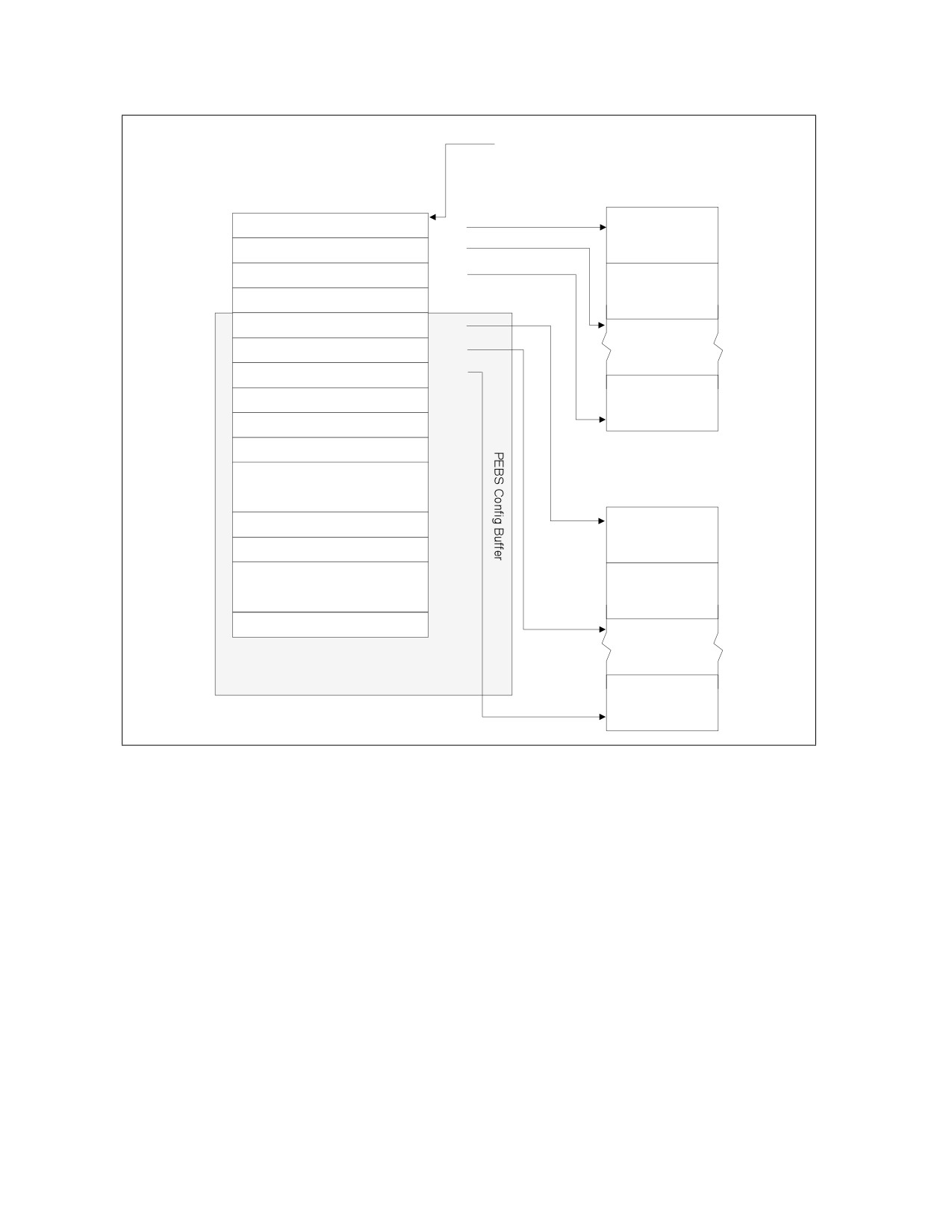
• To properly use PEBS for the additional counters, software will need to set up the counter reset values in PEBS
portion of the DS_BUFFER_MANAGEMENT_AREA data structure that is indicated by the IA32_DS_AREA
register. The layout of the DS_BUFFER_MANAGEMENT_AREA is shown in Figure 20-67. When a counter
generates a PEBS records, the appropriate counter reset values will be loaded into that counter. In the above
example where general purpose counter 2 and fixed function counter 0 generated the PEBS record, general
purpose counter 2 would be reloaded with the value contained in PEBS GP Counter 2 Reset (offset 50H) and
fixed function counter 0 would be reloaded with the value contained in PEBS Fixed Counter 0 Reset (offset
80H).
Vol. 3B
20-143
PERFORMANCE MONITORING
IA32_DS_AREA MSR
DS Buffer Management
BTS Buffer
63
BTS Buffer Base
0
00H
Branch Record 0
BTS Index
08H
BTS Absolute Maximum
10H
Branch Record 1
BTS Interrupt Threshold
18H
PEBS Buffer Base
20H
PEBS Index
28H
PEBS Absolute Maximum
30H
PEBS Interrupt Threshold
38H
Branch Record N
PEBS GP Counter 0 Reset
40H
PEBS GP Counter 1 Reset
●●●
PEBS Buffer
PEBS GP Counter m Reset
PEBS Record 0
PEBS Fixed Counter 0 Reset
80H
●●●
PEBS Record 1
PEBS Fixed Counter n Reset
PEBS Record N
Figure 20-67. PEBS Programming Environment
Extended PEBS support debuts on Intel Atom® processors based on the Goldmont Plus microarchitecture and
future Intel® Core™ processors based on the Ice Lake microarchitecture.
20.9.2 Adaptive PEBS
The PEBS facility has been enhanced to collect the following CPU state in addition to GPRs, EventingIP, TSC, and
memory access related information collected by legacy PEBS:
• XMM registers
• LBR records (TO/FROM/INFO)
The PEBS record is restructured where fields are grouped into Basic group, Memory group, GPR group, XMM group,
and LBR group. A new register MSR_PEBS_DATA_CFG provides software the capability to select data groups of
interest and thus reduce the record size in memory and record generation latency. Hence, a PEBS record's size and
layout vary based on the selected groups. The MSR also allows software to select LBR depth for branch data
records.
By default, the PEBS record will only contain the Basic group. Optionally, each counter can be configured to
generate a PEBS records with the groups specified in MSR_PEBS_DATA_CFG.
20-144
Vol. 3B
PERFORMANCE MONITORING
Details and examples for the Adaptive PEBS capability follow below.
20.9.2.1 Adaptive_Record Counter Control
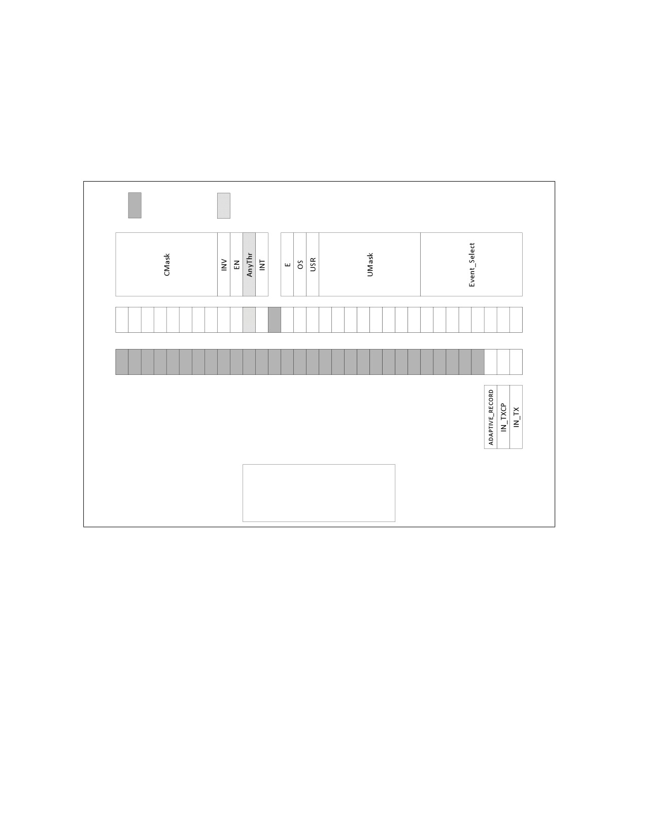
• IA32_PERFEVTSELx.Adaptive_Record[34]: If this bit is set and IA32_PEBS_ENABLE.PEBS_EN_PMCx is set for
the corresponding GP counter, an overflow of PMCx results in generation of an adaptive PEBS record with state
information based on the selections made in MSR_PEBS_DATA_CFG. If this bit is not set, a basic record is
generated.
Reserved
Deprecated
31
23
15
7
0
63
55
47
39
32
IA32_PerfEvtSelX
Address Range: 0x186 to 0x18D
Scope: Thread
Reset value: 0x00000000.0000000
Figure 20-68. Layout of IA32_PerfEvtSelX MSR Supporting Adaptive PEBS
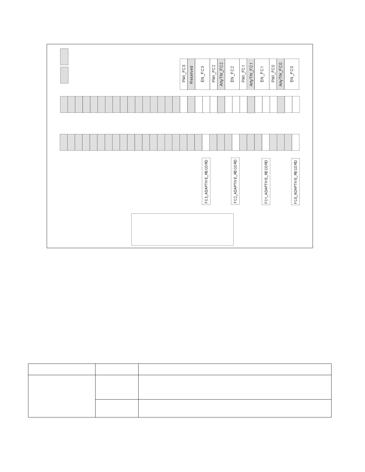
• IA32_FIXED_CTR_CTRL.FCx_Adaptive_Record: If this bit is set and IA32_PEBS_ENABLE.PEBS_EN_FIXEDx is
set for the corresponding Fixed counter, an overflow of FixedCtrx results in generation of an adaptive PEBS
record with state information based on the selections made in MSR_PEBS_DATA_CFG. If this bit is not set, a
basic record is generated.
Vol. 3B
20-145
PERFORMANCE MONITORING
Reserved
Deprecated
23
15
7
0
31
55
47
39
32
63
IA32_Fixed_CTR_CTRL
Add ress: 3 8DH
Scope: Thread
Reset value: 0 x0 000000 0.0 00000 00
Figure 20-69. Layout of IA32_FIXED_CTR_CTRL MSR Supporting Adaptive PEBS
20.9.2.2 PEBS Record Format
The data fields in the PEBS record are aggregated into five groups which are described in the sub-sections below.
Processors that support Adaptive PEBS implement a new MSR called MSR_PEBS_DATA_CFG which allows software
to select the data groups to be captured. The data groups are not placed at fixed locations in the PEBS record, but
are positioned immediately after one another, thus making the record format/size variable based on the groups
selected.
20.9.2.2.1 Basic Info
The Basic group contains essential information for software to parse a record along with several critical fields. It is
always collected.
Table 20-92. Basic Info Group
Field Name
Bit Width
Description
Record Format
[47:0]
This field indicates which data groups are included in the record. The field is zero if
none of the counters that triggered the current PEBS record have their
Adaptive_Record bit set. Otherwise it contains the value of MSR_PEBS_DATA_CFG.
[63:48]
This field provides the size of the current record in bytes. Selected groups are
packed back-to-back in the record without gaps or padding for unselected groups.
20-146
Vol. 3B

PERFORMANCE MONITORING
Table 20-92. Basic Info Group (Contd.)
Instruction Pointer
[63:0]
This field reports the Eventing Instruction Pointer (EventingIP) of the retired
instruction that triggered the PEBS record generation. Note that this field is
different than R/EIP which records the instruction pointer of the next instruction
to be executed after record generation. The legacy R/EIP field has been removed.
Applicable Counters
[63:0]
The Applicable Counters field indicates which counters triggered the generation of
the PEBS record, linking the record to specific events. This allows software to
correlate the PEBS record entry properly with the instruction that caused the
event, even when multiple counters are configured to generate PEBS records and
multiple bits are set in the field.
TSC
[63:0]
This field provides the time stamp counter value when the PEBS record was
generated.
20.9.2.2.2 Memory Access Info
This group contains the legacy PEBS memory-related fields; see Section 20.3.1.1.2.
Table 20-93. Memory Access Info Group
Field Name
Bit Width
Description
Memory Access Address
[63:0]
This field contains the linear address of the source of the load, or linear address of
the destination (target) of the store. This value is written as a 64-bit address in
canonical form.
Memory Auxiliary Info
[63:0]
When a MEM_TRANS_RETIRED.* event is configured in a General Purpose counter,
this field contains an encoded value indicating the memory hierarchy source which
satisfied the load. These encodings are detailed in Table 20-4 and Table 20-13. If
the PEBS assist was triggered for a store uop, this field will contain information
indicating the status of the store, as detailed in Table 20-14.
Memory Access Latency1
[63:0]
When a MEM_TRANS_RETIRED.* event is configured in a General Purpose counter,
this field contains the latency to service the load in core clock cycles.
TSX Auxiliary Info
[31:0]
This field contains the number of cycles in the last TSX region, regardless of
whether that region had aborted or committed.
[63:32]
This field contains the abort details. Refer to Section 20.3.6.5.1.
NOTES:
1. In certain conditions, high latencies in fields under “Memory Access Latency” may be observed even when the Data Src of the “Mem-
ory Auxiliary Info” field indicates a close source.
Beginning with 12th generation Intel Core processors, the memory access information group has been updated.
New fields added are shaded gray in Table 20-94.
Vol. 3B
20-147

PERFORMANCE MONITORING
Table 20-94. Updated Memory Access Info Group
Field Name
Sub-field Name
Bits
Description
Access Address
DLA
[63:0]
This field reports the data linear address (DLA) of the memory access in
(offset 0H)
canonical form.
A zero value indicates the processor could not retrieve the address of the
particular access.
Access Info
Data Src
[3:0]
An encoded value indicating the memory hierarchy source which satisfied the
(offset 8H)
access. These encodings are detailed in Table 20-4.
A zero value indicates the processor could not retrieve the data source of the
particular access.
STLB-miss
[4]
A value of 1 indicates the access has missed the Second-level TLB (STLB).
Is-Lock
[5]
A value of 1 indicates the access was part of a locked (atomic) memory trans-
action.
Data-Blk
[6]
A value of 1 indicates the load was blocked since its data could not be forwarded
from a preceding store.
Address-Blk
[7]
A value of 1 indicates the load was blocked due to potential address conflict with
a preceding store.
Access Latency
Instruction
[15:0]
Measured instruction latency in core cycles.
Latency
(offset 10H)
For loads, the latency starts by the dispatch of the load operation for execution
and lasts until completion of the instruction it belongs to.
This field includes the entire latency including time for data-dependency
resolution or TLB lookups.
Cache Latency
[47:32]
Measured cache access latency in core cycles.
For loads, the latency starts by the actual cache access until the data is returned
by the memory subsystem.
For stores, the latency starts when the demand write accesses the L1 data-
cache and lasts until the cacheline write is completed in the memory subsystem.
This field does not include non-data-cache latency such as memory ordering
checks or TLB lookups.
TSX
Transaction
[31:0]
This field contains the number of cycles in the last TSX region, regardless of
Latency
whether that region had aborted or committed.
(offset 18H)
Abort Info
[63:32]
This field contains the abort details. Refer to Section 20.3.6.5.1.
To determine which fields are supported for certain performance monitoring events, consult the Memory Info attri-
bute in the event lists at https://download.01.org/perfmon/.
NOTE
There may be additional block reasons, even if Data-Blk and Address-Blk are both clear, e.g., non-
optimal instruction latency.
On P-core, the new Data-Blk and Address-Blk bits require the event LD_BLOCKS.STORE_FORWARD
(r8203) to be configured in a programmable counter.
20.9.2.2.3 GPRs
This group is captured when the GPR bit is enabled in MSR_PEBS_DATA_CFG. GPRs are always 64 bits wide. If they
are selected for non 64-bit mode, the upper 32-bit of the legacy RAX - RDI and all contents of R8-15 GPRs will be
filled with 0s. In 64bit mode, the full 64 bit value of each register is written.
20-148
Vol. 3B

PERFORMANCE MONITORING
The order differs from legacy. The table below shows the order of the GPRs in Ice Lake microarchitecture.
Table 20-95. GPRs in Ice Lake Microarchitecture
Field Name
Bit Width
RFLAGS
[63:0]
RIP
[63:0]
RAX
[63:0]
RCX*
[63:0]
RDX*
[63:0]
RBX*
[63:0]
RSP*
[63:0]
RBP*
[63:0]
RSI*
[63:0]
RDI*
[63:0]
R8
[63:0]
R15
[63:0]
The machine state reported in the PEBS record is the committed machine state immediately after the instruction
that triggers PEBS completes.
For instance, consider the following instruction sequence:
MOV eax, [eax]; triggers PEBS record generation
NOP
If the mov instruction triggers PEBS record generation, the EventingIP field in the PEBS record will report the
address of the mov, and the value of EAX in the PEBS record will show the value read from memory, not the target
address of the read operation. And the value of RIP will contain the linear address of the nop.
20.9.2.2.4 XMMs
This group is captured when the XMM bit is enabled in MSR_PEBS_DATA_CFG and SSE is enabled. If SSE is not
enabled, the fields will contain zeroes. XMM8-XMM15 will also contain zeroes if not in 64-bit mode.
Table 20-96. XMMs
Field Name
Bit Width
XMM0
[127:0]
XMM15
[127:0]
Vol. 3B
20-149
PERFORMANCE MONITORING
20.9.2.2.5 LBRs
To capture LBR data in the PEBS record, the LBR bit in MSR_PEBS_DATA_CFG must be enabled. The number of LBR
entries included in the record can be configured in the LBR_entries field of MSR_PEBS_DATA_CFG.
Table 20-97. LBRs
Field Name
Bit Width
Description
LBR[].FROM
[63:0]
Branch from address.
LBR[].TO
[63:0]
Branch to address.
LBR[].INFO
[63:0]
Other LBR information, like timing. This field is described in more
detail in Section 18.12.1, “MSR_LBR_INFO_x MSR.”
LBR entries are recorded into the record starting at LBR[TOS] and proceeding to LBR[TOS-1] and following. Note
that LBR index is modulo the number of LBRs supporting on the processor.
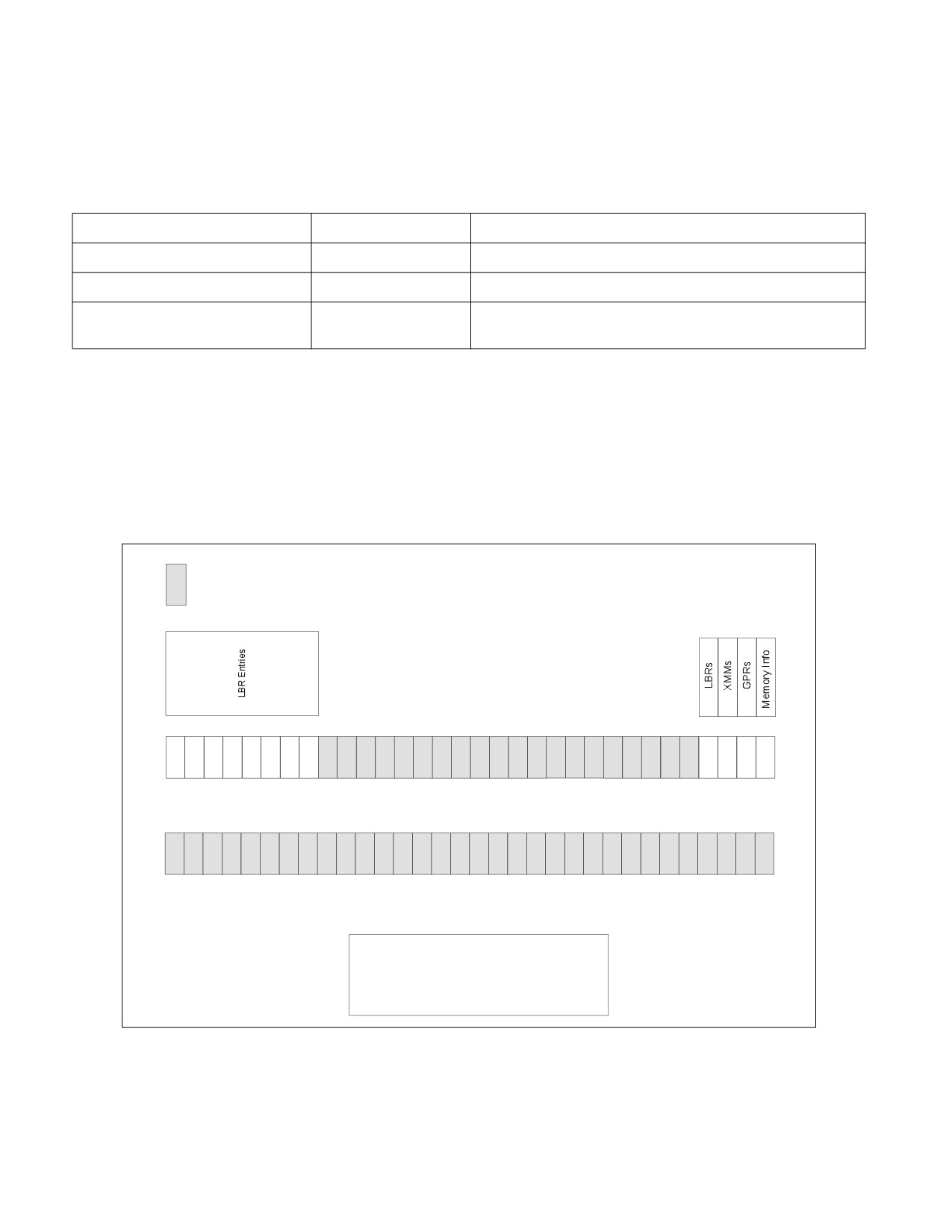
20.9.2.3 MSR_PEBS_DATA_CFG
Bits in MSR_PEBS_DATA_CFG can be set to include data field blocks/groups into adaptive records. The Basic Info
group is always included in the record. Additionally, the number of LBR entries included in the record is configu-
rable.
Reserved
23
15
7
31
31
55
47
39
63
63
MSR_PEBS_DATA_CFG
Address: 3F2H
Scope: Thread
Reset value : 0x00000000 .00000000
Figure 20-70. MSR_PEBS_DATA_CFG
20-150
Vol. 3B

PERFORMANCE MONITORING
Table 20-98. MSR_PEBS_CFG Programming1
Bit
Bit Index
Access
Description
Memory Info
0
R/W
Setting this bit will capture memory information such as the linear address,
data source and latency of the memory access in the PEBS record.
GPRs
1
R/W
Setting this bit will capture the contents of the General Purpose registers
in the PEBS record.
XMMs
2
R/W
Setting this bit will capture the contents of the XMM registers in the PEBS
record.
LBRs
3
R/W
Setting this bit will capture LBR TO, FROM, and INFO in the PEBS record.
Reserved2
23:4
NA
Reserved
LBR Entries
31:24
R/W
Set the field to the desired number of entries minus 1. For example, if the
LBR_entries field is 0, a single entry will be included in the record. To
include 32 LBR entries, set the LBR_entries field to 31 (0x1F). To ensure
all PEBS records are 16-byte aligned, it is recommended to select an even
number of LBR entries (programmed into LBR_entries as an odd number).
NOTES:
1. A write to the MSR will be ignored when IA32_MISC_ENABLE.PERFMON_AVAILABLE is zero (default).
2. Writing to the reserved bits will cause a GP fault.
20.9.2.4 PEBS Record Examples
The following example shows the layout of the PEBS record when all data groups are selected (all valid bits in
MSR_PEBS_DATA_CFG are set) and maximum number of LBRs are selected. There are no gaps in the PEBS record
when a subset of the groups are selected, thus keeping the layout compact. Implementations that do not support
some features will have to pad zeroes in the corresponding fields.
Table 20-99. PEBS Record Example 1
Offset
Group Name
Field Name
Legacy Name (If Different)
0x0
Basic Info
Record Format
New
Record Size
New
0x8
Instruction Pointer
EventingRIP
0x10
Applicable Counters
0x18
TSC
0x20
Memory Info
Memory Access Address
DLA
0x28
Memory Auxiliary Info
DATA_SRC
0x30
Memory Access Latency
Load Latency
0x38
TSX Auxiliary Info
HLE Information
Vol. 3B
20-151

PERFORMANCE MONITORING
Table 20-99. PEBS Record Example 1
0x40
GPRs
RFLAGS
0x48
RIP
0x50
RAX
0x88
RDI
0x90
R8
0xC8
R15
0xD0
XMMs
XMM0
New
0x1C0
XMM15
0x1D0
LBRs
LBR[TOS].FROM
New
0x1D8
LBR[TOS].TO
0x1E0
LBR[TOS].INFO
0x4B8
LBR[TOS +1].FROM
0x4C0
LBR[TOS +1].TO
0x4C8
LBR[TOS +1].INFO
The following example shows the layout of the PEBS record when Basic, GPR, and LBR group with 3 LBR entries are
selected.
Table 20-100. PEBS Record Example 2
Offset
Group Name
Field Name
Legacy Name (If Different)
0x0
Basic Info
Record Format
New
Record Size
New
0x8
Instruction Pointer
EventingRIP
0x10
Applicable Counters
0x18
TSC
20-152
Vol. 3B

PERFORMANCE MONITORING
Table 20-100. PEBS Record Example 2
0x20
GPRs
RFLAGS
0x28
RIP
0x30
RAX
0x68
RDI
0x70
R8
0xA8
R15
0xB0
LBRs
LBR[TOS].FROM
New
0xB8
LBR[TOS].TO
0xC0
LBR[TOS].INFO
0xE0
LBR[TOS +1].FROM
0xE8
LBR[TOS +1].TO
0xF0
LBR[TOS +1].INFO
20.9.3 Precise Distribution of Instructions Retired (PDIR) Facility
Precise Distribution of Instructions Retired Facility is available via PEBS on some microarchitectures. Refer to
Section 20.3.4.4.4. Counters that support PDIR also vary. See the processor specific sections for availability.
20.9.4 Reduced Skid PEBS
For precise events, upon triggering a PEBS assist, there will be a finite delay between the time the counter over-
flows and when the microcode starts to carry out its data collection obligations. The Reduced Skid mechanism miti-
gates the “skid” problem by providing an early indication of when the counter is about to overflow, allowing the
machine to more precisely trap on the instruction that actually caused the counter overflow thus greatly reducing
skid.
This mechanism is a superset of the PDIR mechanism available in the Sandy Bridge microarchitecture. See Section
20.3.4.4.4
In the Goldmont microarchitecture, the mechanism applies to all precise events including, INST_RETIRED, except
for UOPS_RETIRED. However, the Reduced Skid mechanism is disabled for any counter when the INV, ANY, E, or
CMASK fields are set.
With Reduced Skid PEBS, the skid is precisely one event occurrence. Hence if counting INST_RETIRED, PEBS will
indicate the instruction that follows that which caused the counter to overflow.
For the Reduced Skid mechanism to operate correctly, the performance monitoring counters should not be recon-
figured or modified when they are running with PEBS enabled. The counters need to be disabled (e.g., via
IA32_PERF_GLOBAL_CTRL MSR) before changes to the configuration (e.g., what event is specified in IA32_PERFE-
VTSELx or whether PEBS is enabled for that counter via IA32_PEBS_ENABLE) or counter value (MSR write to
IA32_PMCx and IA32_A_PMCx).
Vol. 3B
20-153

PERFORMANCE MONITORING
20.9.5 EPT-Friendly PEBS
The 3rd generation Intel Xeon Scalable Family of processors based on Ice Lake microarchitecture (and later proces-
sors) and the 12th generation Intel Core processor (and later processors) support VMX guest use of PEBS when the
DS Area (including the PEBS Buffer and DS Management Area) is allocated from a paged pool of EPT pages. In such
a configuration PEBS DS Area accesses may result in VM exits (e.g., EPT violations due to “lazy” EPT page-table
entry propagation), and in such cases the PEBS record will not be lost but instead will “skid” to after the subsequent
VM Entry back to the guest. For precise events the guest will observe that the record skid by one event occurrence,
while for non-precise events the record will skid by one instruction.
20.9.6 PDist: Precise Distribution
PDist eliminates any skid or shadowing effects from PEBS. With PDist, the PEBS record will be generated precisely
upon completion of the instruction or operation that causes the counter to overflow (there is no “wait for next
occurrence” by default).
PDist is supported by selected counters, and is only supported when those counters are programmed to count
select precise events1. The legacy PEBS behavior applies to counters that do not support PDist, unless specified
otherwise. PDist requires that the INV, ANY, E, and CMASK fields are cleared. Which counters support PDist, and
which events are supported for PDist, is model-specific. Further, the counter reload value must not be lesser than
127 for PDist to operate.
For the PDist mechanism to operate correctly, the performance monitoring counters should not be reconfigured or
modified when they are running with PEBS enabled. The counters need to be disabled (e.g., via IA32_PERF_-
GLOBAL_CTRL MSR) before changes to the configuration (e.g., what event is specified in IA32_PERFEVTSELx or
whether PEBS is enabled for that counter via IA32_PEBS_ENABLE) or counter value (MSR write to IA32_PMCx and
IA32_A_PMCx).
20.9.7 Load Latency Facility
The load latency facility provides software a means to characterize the latencies of memory load operations to
different levels of cache/memory hierarchy. This facility requires a processor supporting the enhanced PEBS record
format in the PEBS buffer.
Beginning with 12th generation Intel Core processors, the load latency facility supports all fields in Table 20-94,
“Updated Memory Access Info Group,” in addition to the Memory Access Address field:
• The Instruction Latency field measures the load latency from the load's first dispatch until final data
writeback from the memory subsystem. The latency is reported for retired demand load operations and in core
cycles (it accounts for re-dispatches and data dependencies).
• The Cache Latency field measures the subset of cache access latency in core cycles. It starts from the actual
cache access until the data is returned by the memory subsystem The latency is reported for retired demand
load operations in core cycles (it does not account for memory ordering blocks).
• The Data Source field is an encoded value indicates the origin of the data obtained by the load instruction. The
encoding is shown in Table 20-101. In the descriptions, local memory refers to system memory physically
attached to a processor package, and remote memory refers to system memory or cache physically attached
to another processor package (in a server product).
• Through the Access Info field, load latency features binary indications on certain blocks that the load
operation may have encountered. Refer to STLB-miss, Is-Lock, Data-Blk and Address-Blk fields in Table 20-94.
NOTE
For loads triggered by software prefetch instructions, the cache related fields including Data Source
and Cache Latency, report values as if the load was an L1 cache hit (the prefetch completes without
waiting for data return, for performance reasons).
1. To determine whether an event is precise or supports PDist, consult the relevant attribute in the event lists at https://down-
load.01.org/perfmon/.
20-154
Vol. 3B

PERFORMANCE MONITORING
Table 20-101. Data Source Encoding for Memory Accesses (Ice Lake and Later Microarchitectures)
Encoding
Description
00H
Unknown Data Source (the processor could not retrieve the origin of this request).
01H
L1 HIT. This request was satisfied by the L1 data cache. (Minimal latency core cache hit.)
02H
FB HIT. This request was merged into an outstanding cache miss to same cache-line address.
03H
L2 HIT. This request was satisfied by the L2 cache.
04H
L3 HIT. This request was satisfied by the L3 cache with no coherency actions performed (snooping).
05H
XCORE MISS. This request was satisfied by the L3 cache but involved a coherency check in some sibling core(s).
06H
XCORE HIT. This request was satisfied by the L3 cache but involved a coherency check that hit a non-modified copy in
a sibling core.
07H
XCORE FWD. This request was satisfied by a sibling core where either a modified (cross-core HITM) or a non-modified
(cross-core FWD) cache-line copy was found.
08H
Local Far Memory. This request has missed the L3 cache and was serviced by local far memory.
09H
Remote Far Memory. This request has missed the L3 cache and was serviced by remote far memory.
0AH
Local Near Memory. This request has missed the L3 cache and was serviced by local near memory.
0BH
Remote Near Memory. This request has missed the L3 cache and was serviced by remote near memory.
0CH
Remote FWD. This request has missed the L3 cache and a non-modified cache-line copy was forwarded from a
remote cache.
0DH
Remote HITM. This request has missed the L3 cache and a modified cache-line was forwarded from a remote cache.
0EH
I/O. Request of input/output operation.
0FH
UC. The request was to uncacheable memory.
To use this feature, software must complete the following steps:
• Complete the PEBS configuration steps.
• Set the Memory Info bit in the PEBS_DATA_CFG MSR.
• One of the relevant IA32_PERFEVTSELx MSRs is programmed to specify the event unit MEM_TRANS_RE-
TIRED.LOAD_LATENCY (IA32_PerfEvtSelX[15:0] = 1CDH). The corresponding counter, IA32_PMCx, will
accumulate event counts for architecturally visible loads which exceed the programmed latency threshold
specified separately in an MSR. Stores are ignored when this event is programmed. The CMASK or INV fields of
the IA32_PerfEvtSelX register used for counting load latency must be 0. Writing other values will result in
undefined behavior.
• The MSR_PEBS_LD_LAT_THRESHOLD MSR is programmed with the desired latency threshold in core clock
cycles. Loads with instruction latency greater than this value are eligible for counting and PEBS data reporting.
The minimum value that may be programmed in this register is 1.
• The PEBS enable bit in the IA32_PEBS_ENABLE register is set for the corresponding IA32_PMCx counter
register.
Refer to Section 20.3.4.4.2 for further implementation details of Load Latency.
20.9.8 Store Latency Facility
Store latency support is available on the 12th generation Intel Core processor. Store latency is a PEBS extension
that provides a means to profile store memory accesses in the system. It complements the load latency facility.
Store latency leverages the PEBS facility where it can provide additional information about sampled stores. The
additional information includes the data address, memory auxiliary information, and the cache latency of the store
access. Normal stores (those preceded with a read-for-ownership) as well as streaming stores are supported by
the store latency facility.
Vol. 3B
20-155

PERFORMANCE MONITORING
Memory store operations typically do not limit performance since they update the memory with no operation that
directly depends on them. Thus, data out of this facility should be carefully used once stores are suspected as a
performance limiter; for example, once the TMA node of Backend_Bound.Memory_Bound.Store_Bound is flagged1.
To enable the store latency facility, software must complete the following steps:
• Complete the PEBS configuration steps.
• Set the Memory Info bit in the PEBS_DATA_CFG MSR.
• Program the MEM_TRANS_RETIRED.STORE_SAMPLE event on general-purpose performance-monitoring
counter 0 (IA32_PERFEVTSEL0[15:0] = 2CDH).
• Setup the PEBS buffer to hold at least two records, setting both ‘PEBS Absolute Maximum’ and ‘PEBS Interrupt
Threshold’, should any other counter be used by PEBS (that is whenever IA32_PEBS_ENABLE[x] ≠ 0 for x ≠ 0).
• Set IA32_PEBS_ENABLE[0].
The store latency information is written into a PEBS record as shown in Table 20-48.
The store latency relies on the PEBS facility, so the PEBS configuration must be completed first. Unlike load latency,
there is no option to filter on a subset of stores that exceed a certain threshold.
1. For more details about the method, refer to Section B.1, “Top-Down Analysis Method” of the Intel® 64 and IA-32 Architectures Opti-
mization Reference Manual.
20-156
Vol. 3B

CHAPTER 21
8086 EMULATION
IA-32 processors (beginning with the Intel386 processor) provide two ways to execute new or legacy programs
that are assembled and/or compiled to run on an Intel 8086 processor:
• Real-address mode.
• Virtual-8086 mode.
Figure 2-3 shows the relationship of these operating modes to protected mode and system management mode
(SMM).
When the processor is powered up or reset, it is placed in the real-address mode. This operating mode almost
exactly duplicates the execution environment of the Intel 8086 processor, with some extensions. Virtually any
program assembled and/or compiled to run on an Intel 8086 processor will run on an IA-32 processor in this mode.
When running in protected mode, the processor can be switched to virtual-8086 mode to run 8086 programs. This
mode also duplicates the execution environment of the Intel 8086 processor, with extensions. In virtual-8086
mode, an 8086 program runs as a separate protected-mode task. Legacy 8086 programs are thus able to run
under an operating system (such as Microsoft Windows*) that takes advantage of protected mode and to use
protected-mode facilities, such as the protected-mode interrupt- and exception-handling facilities. Protected-mode
multitasking permits multiple virtual-8086 mode tasks (with each task running a separate 8086 program) to be run
on the processor along with other non-virtual-8086 mode tasks.
This section describes both the basic real-address mode execution environment and the virtual-8086-mode execu-
tion environment, available on the IA-32 processors beginning with the Intel386 processor.
21.1
REAL-ADDRESS MODE
The IA-32 architecture’s real-address mode runs programs written for the Intel 8086, Intel 8088, Intel 80186, and
Intel 80188 processors, or for the real-address mode of the Intel 286, Intel386, Intel486, Pentium, P6 family,
Pentium 4, and Intel Xeon processors.
The execution environment of the processor in real-address mode is designed to duplicate the execution environ-
ment of the Intel 8086 processor. To an 8086 program, a processor operating in real-address mode behaves like a
high-speed 8086 processor. The principal features of this architecture are defined in Chapter 3, “Basic Execution
Environment,” of the Intel® 64 and IA-32 Architectures Software Developer’s Manual, Volume 1.
The following is a summary of the core features of the real-address mode execution environment as would be seen
by a program written for the 8086:
• The processor supports a nominal 1-MByte physical address space (see Section 21.1.1, “Address Translation in
Real-Address Mode,” for specific details). This address space is divided into segments, each of which can be up
to 64 KBytes in length. The base of a segment is specified with a 16-bit segment selector, which is shifted left
by 4 bits to form a 20-bit offset from address 0 in the address space. An operand within a segment is addressed
with a 16-bit offset from the base of the segment. A physical address is thus formed by adding the offset to the
20-bit segment base (see Section 21.1.1, “Address Translation in Real-Address Mode”).
• All operands in “native 8086 code” are 8-bit or 16-bit values. (Operand size override prefixes can be used to
access 32-bit operands.)
• Eight 16-bit general-purpose registers are provided: AX, BX, CX, DX, SP, BP, SI, and DI. The extended 32 bit
registers (EAX, EBX, ECX, EDX, ESP, EBP, ESI, and EDI) are accessible to programs that explicitly perform a size
override operation.
• Four segment registers are provided: CS, DS, SS, and ES. (The FS and GS registers are accessible to programs
that explicitly access them.) The CS register contains the segment selector for the code segment; the DS and
ES registers contain segment selectors for data segments; and the SS register contains the segment selector
for the stack segment.
• The 8086 16-bit instruction pointer (IP) is mapped to the lower 16-bits of the EIP register. Note this register is
a 32-bit register and unintentional address wrapping may occur.
Vol. 3B
21-1
8086 EMULATION
• The 16-bit FLAGS register contains status and control flags. (This register is mapped to the 16 least significant
bits of the 32-bit EFLAGS register.)
• All of the Intel 8086 instructions are supported (see Section 21.1.3, “Instructions Supported in Real-Address
Mode”).
• A single, 16-bit-wide stack is provided for handling procedure calls and invocations of interrupt and exception
handlers. This stack is contained in the stack segment identified with the SS register. The SP (stack pointer)
register contains an offset into the stack segment. The stack grows down (toward lower segment offsets) from
the stack pointer. The BP (base pointer) register also contains an offset into the stack segment that can be used
as a pointer to a parameter list. When a CALL instruction is executed, the processor pushes the current
instruction pointer (the 16 least-significant bits of the EIP register and, on far calls, the current value of the CS
register) onto the stack. On a return, initiated with a RET instruction, the processor pops the saved instruction
pointer from the stack into the EIP register (and CS register on far returns). When an implicit call to an interrupt
or exception handler is executed, the processor pushes the EIP, CS, and EFLAGS (low-order 16-bits only)
registers onto the stack. On a return from an interrupt or exception handler, initiated with an IRET instruction,
the processor pops the saved instruction pointer and EFLAGS image from the stack into the EIP, CS, and
EFLAGS registers.
• A single interrupt table, called the “interrupt vector table” or “interrupt table,” is provided for handling
interrupts and exceptions (see Figure 21-2). The interrupt table (which has 4-byte entries) takes the place of
the interrupt descriptor table (IDT, with 8-byte entries) used when handling protected-mode interrupts and
exceptions. Interrupt and exception vector numbers provide an index to entries in the interrupt table. Each
entry provides a pointer (called a “vector”) to an interrupt- or exception-handling procedure. See Section
21.1.4, “Interrupt and Exception Handling,” for more details. It is possible for software to relocate the IDT by
means of the LIDT instruction on IA-32 processors beginning with the Intel386 processor.
• The x87 FPU is active and available to execute x87 FPU instructions in real-address mode. Programs written to
run on the Intel 8087 and Intel 287 math coprocessors can be run in real-address mode without modification.
The following extensions to the Intel 8086 execution environment are available in the IA-32 architecture’s real-
address mode. If backwards compatibility to Intel 286 and Intel 8086 processors is required, these features should
not be used in new programs written to run in real-address mode.
• Two additional segment registers (FS and GS) are available.
• Many of the integer and system instructions that have been added to later IA-32 processors can be executed in
real-address mode (see Section 21.1.3, “Instructions Supported in Real-Address Mode”).
• The 32-bit operand prefix can be used in real-address mode programs to execute the 32-bit forms of instruc-
tions. This prefix also allows real-address mode programs to use the processor’s 32-bit general-purpose
registers.
• The 32-bit address prefix can be used in real-address mode programs, allowing 32-bit offsets.
The following sections describe address formation, registers, available instructions, and interrupt and exception
handling in real-address mode. For information on I/O in real-address mode, see Chapter 19, “Input/Output,” of
the Intel® 64 and IA-32 Architectures Software Developer’s Manual, Volume 1.
21.1.1 Address Translation in Real-Address Mode
In real-address mode, the processor does not interpret segment selectors as indexes into a descriptor table;
instead, it uses them directly to form linear addresses as the 8086 processor does. It shifts the segment selector
left by 4 bits to form a 20-bit base address (see Figure 21-1). The offset into a segment is added to the base
address to create a linear address that maps directly to the physical address space.
When using 8086-style address translation, it is possible to specify addresses larger than 1 MByte. For example,
with a segment selector value of FFFFH and an offset of FFFFH, the linear (and physical) address would be 10FFEFH
(1 megabyte plus 64 KBytes). The 8086 processor, which can form addresses only up to 20 bits long, truncates the
high-order bit, thereby “wrapping” this address to FFEFH. When operating in real-address mode, however, the
processor does not truncate such an address and uses it as a physical address. (Note, however, that for IA-32
processors beginning with the Intel486 processor, the A20M# signal can be used in real-address mode to mask
address line A20, thereby mimicking the 20-bit wrap-around behavior of the 8086 processor.) Care should be take
to ensure that A20M# based address wrapping is handled correctly in multiprocessor based system.
21-2
Vol. 3B

8086 EMULATION
19
4
3
0
Base
16-bit Segment Selector
0 0 0 0
+
19
16
15
0
Offset
0 0 0 0
16-bit Effective Address
=
19
0
Linear
20-bit Linear Address
Address
Figure 21-1. Real-Address Mode Address Translation
The IA-32 processors beginning with the Intel386 processor can generate 32-bit offsets using an address override
prefix; however, in real-address mode, the value of a 32-bit offset may not exceed FFFFH without causing an
exception.
For full compatibility with Intel 286 real-address mode, pseudo-protection faults (interrupt 12 or 13) occur if a 32-
bit offset is generated outside the range 0 through FFFFH.
21.1.2 Registers Supported in Real-Address Mode
The register set available in real-address mode includes all the registers defined for the 8086 processor plus the
new registers introduced in later IA-32 processors, such as the FS and GS segment registers, the debug registers,
the control registers, and the floating-point unit registers. The 32-bit operand prefix allows a real-address mode
program to use the 32-bit general-purpose registers (EAX, EBX, ECX, EDX, ESP, EBP, ESI, and EDI).
21.1.3 Instructions Supported in Real-Address Mode
The following instructions make up the core instruction set for the 8086 processor. If backwards compatibility to
the Intel 286 and Intel 8086 processors is required, only these instructions should be used in a new program
written to run in real-address mode.
• Move (MOV) instructions that move operands between general-purpose registers, segment registers, and
between memory and general-purpose registers.
• The exchange (XCHG) instruction.
• Load segment register instructions LDS and LES.
• Arithmetic instructions ADD, ADC, SUB, SBB, MUL, IMUL, DIV, IDIV, INC, DEC, CMP, and NEG.
• Logical instructions AND, OR, XOR, and NOT.
• Decimal instructions DAA, DAS, AAA, AAS, AAM, and AAD.
• Stack instructions PUSH and POP (to general-purpose registers and segment registers).
• Type conversion instructions CWD, CDQ, CBW, and CWDE.
• Shift and rotate instructions SAL, SHL, SHR, SAR, ROL, ROR, RCL, and RCR.
• TEST instruction.
• Control instructions JMP, Jcc, CALL, RET, LOOP, LOOPE, and LOOPNE.
• Interrupt instructions INT n, INTO, and IRET.
• EFLAGS control instructions STC, CLC, CMC, CLD, STD, LAHF, SAHF, PUSHF, and POPF.
• I/O instructions IN, INS, OUT, and OUTS.
• Load effective address (LEA) instruction, and translate (XLATB) instruction.
Vol. 3B
21-3
8086 EMULATION
• LOCK prefix.
• Repeat prefixes REP, REPE, REPZ, REPNE, and REPNZ.
• Processor halt (HLT) instruction.
• No operation (NOP) instruction.
The following instructions, added to later IA-32 processors (some in the Intel 286 processor and the remainder in
the Intel386 processor), can be executed in real-address mode, if backwards compatibility to the Intel 8086
processor is not required.
• Move (MOV) instructions that operate on the control and debug registers.
• Load segment register instructions LSS, LFS, and LGS.
• Generalized multiply instructions and multiply immediate data.
• Shift and rotate by immediate counts.
• Stack instructions PUSHA, PUSHAD, POPA, POPAD, and PUSH immediate data.
• Move with sign extension instructions MOVSX and MOVZX.
• Long-displacement Jcc instructions.
• Exchange instructions CMPXCHG, CMPXCHG8B, and XADD.
• String instructions MOVS, CMPS, SCAS, LODS, and STOS.
• Bit test and bit scan instructions BT, BTS, BTR, BTC, BSF, and BSR; the byte-set-on condition instruction SETcc;
and the byte swap (BSWAP) instruction.
• Double shift instructions SHLD and SHRD.
• EFLAGS control instructions PUSHF and POPF.
• ENTER and LEAVE control instructions.
• BOUND instruction.
• CPU identification (CPUID) instruction.
• System instructions CLTS, INVD, WINVD, INVLPG, LGDT, SGDT, LIDT, SIDT, LMSW, SMSW, RDMSR, WRMSR,
RDTSC, and RDPMC.
Execution of any of the other IA-32 architecture instructions (not given in the previous two lists) in real-address
mode result in an invalid-opcode exception (#UD) being generated.
21.1.4 Interrupt and Exception Handling
When operating in real-address mode, software must provide interrupt and exception-handling facilities that are
separate from those provided in protected mode. Even during the early stages of processor initialization when the
processor is still in real-address mode, elementary real-address mode interrupt and exception-handling facilities
must be provided to ensure reliable operation of the processor, or the initialization code must ensure that no inter-
rupts or exceptions will occur.
The IA-32 processors handle interrupts and exceptions in real-address mode similar to the way they handle them
in protected mode. When a processor receives an interrupt or generates an exception, it uses the vector number of
the interrupt or exception as an index into the interrupt table. (In protected mode, the interrupt table is called the
interrupt descriptor table (IDT), but in real-address mode, the table is usually called the interrupt vector
table, or simply the interrupt table.) The entry in the interrupt vector table provides a pointer to an interrupt- or
exception-handler procedure. (The pointer consists of a segment selector for a code segment and a 16-bit offset
into the segment.) The processor performs the following actions to make an implicit call to the selected handler:
1. Pushes the current values of the CS and EIP registers onto the stack. (Only the 16 least-significant bits of the
EIP register are pushed.)
2. Pushes the low-order 16 bits of the EFLAGS register onto the stack.
3. Clears the IF flag in the EFLAGS register to disable interrupts.
4. Clears the TF, RF, and AC flags, in the EFLAGS register.
21-4
Vol. 3B
8086 EMULATION
5. Transfers program control to the location specified in the interrupt vector table.
An IRET instruction at the end of the handler procedure reverses these steps to return program control to the inter-
rupted program. Exceptions do not return error codes in real-address mode.
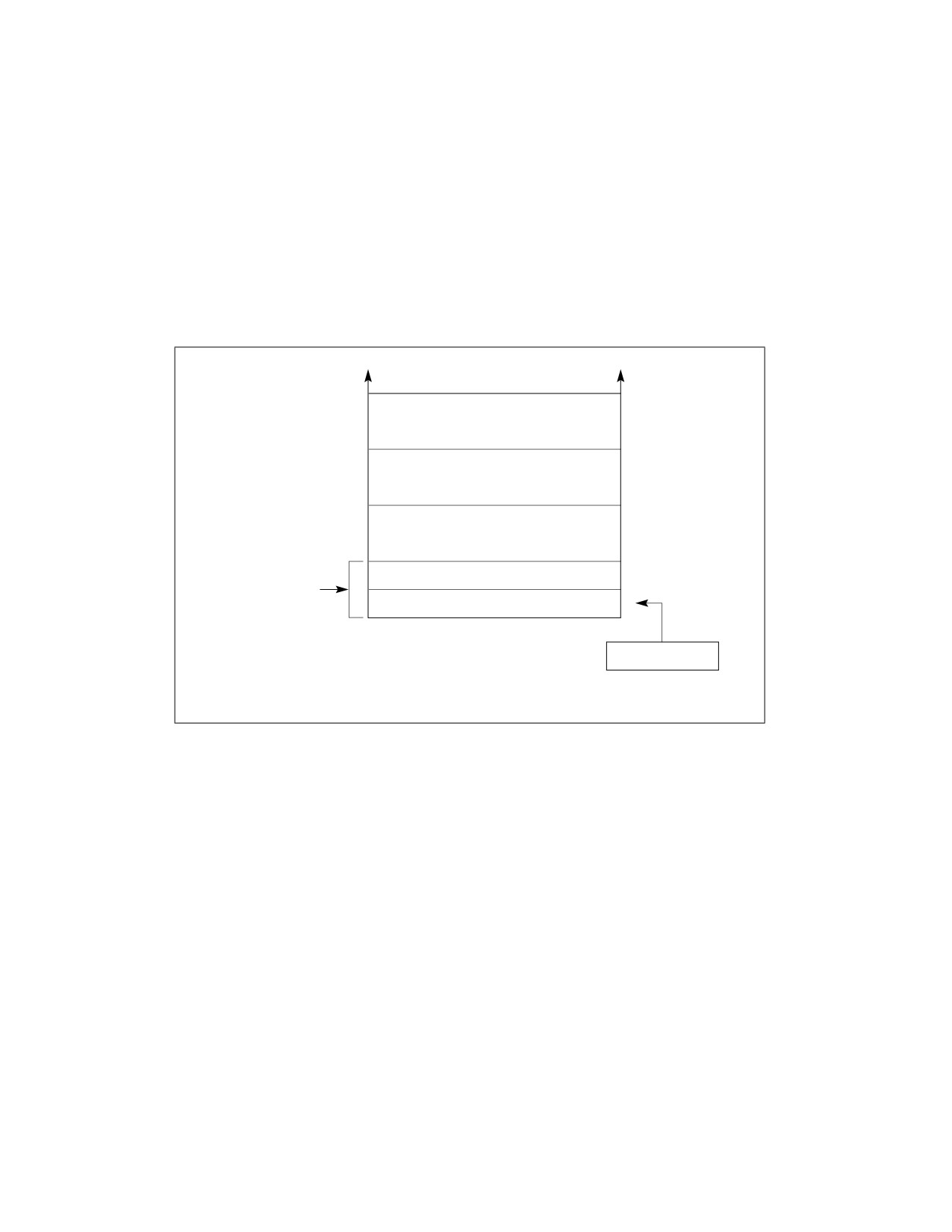
The interrupt vector table is an array of 4-byte entries (see Figure 21-2). Each entry consists of a far pointer to a
handler procedure, made up of a segment selector and an offset. The processor scales the interrupt or exception
vector by 4 to obtain an offset into the interrupt table. Following reset, the base of the interrupt vector table is
located at physical address 0 and its limit is set to 3FFH. In the Intel 8086 processor, the base address and limit of
the interrupt vector table cannot be changed. In the later IA-32 processors, the base address and limit of the inter-
rupt vector table are contained in the IDTR register and can be changed using the LIDT instruction.
(For backward compatibility to Intel 8086 processors, the default base address and limit of the interrupt vector
table should not be changed.)
Up to Entry 255
Entry 3
12
Entry 2
8
Entry 1
4
Segment Selector
2
Interrupt Vector 0*
Offset
0
15
0
* Interrupt vector number 0 selects entry 0
IDTR
(called “interrupt vector 0”) in the interrupt
vector table. Interrupt vector 0 in turn
points to the start of the interrupt handler
for interrupt 0.
Figure 21-2. Interrupt Vector Table in Real-Address Mode
Table 21-1 shows the interrupt and exception vectors that can be generated in real-address mode and virtual-8086
mode, and in the Intel 8086 processor. See Chapter 6, “Interrupt and Exception Handling‚” for a description of the
exception conditions.
21.2
VIRTUAL-8086 MODE
Virtual-8086 mode is actually a special type of a task that runs in protected mode. When the operating-system or
executive switches to a virtual-8086-mode task, the processor emulates an Intel 8086 processor. The execution
environment of the processor while in the 8086-emulation state is the same as is described in Section 21.1, “Real-
Address Mode,” for real-address mode, including the extensions. The major difference between the two modes is
that in virtual-8086 mode the 8086 emulator uses some protected-mode services (such as the protected-mode
interrupt and exception-handling and paging facilities).
Vol. 3B
21-5

8086 EMULATION
As in real-address mode, any new or legacy program that has been assembled and/or compiled to run on an Intel
8086 processor will run in a virtual-8086-mode task. And several 8086 programs can be run as virtual-8086-mode
tasks concurrently with normal protected-mode tasks, using the processor’s multitasking facilities.
Table 21-1. Real-Address Mode Exceptions and Interrupts
Vector
Description
Real-Address Mode
Virtual-8086 Mode
Intel 8086 Processor
No.
0
Divide Error (#DE)
Yes
Yes
Yes
1
Debug Exception (#DB)
Yes
Yes
No
2
NMI Interrupt
Yes
Yes
Yes
3
Breakpoint (#BP)
Yes
Yes
Yes
4
Overflow (#OF)
Yes
Yes
Yes
5
BOUND Range Exceeded (#BR)
Yes
Yes
Reserved
6
Invalid Opcode (#UD)
Yes
Yes
Reserved
7
Device Not Available (#NM)
Yes
Yes
Reserved
8
Double Fault (#DF)
Yes
Yes
Reserved
9
(Intel reserved. Do not use.)
Reserved
Reserved
Reserved
10
Invalid TSS (#TS)
Reserved
Yes
Reserved
11
Segment Not Present (#NP)
Reserved
Yes
Reserved
12
Stack Fault (#SS)
Yes
Yes
Reserved
13
General Protection (#GP)*
Yes
Yes
Reserved
14
Page Fault (#PF)
Reserved
Yes
Reserved
15
(Intel reserved. Do not use.)
Reserved
Reserved
Reserved
16
Floating-Point Error (#MF)
Yes
Yes
Reserved
17
Alignment Check (#AC)
Reserved
Yes
Reserved
18
Machine Check (#MC)
Yes
Yes
Reserved
19-31
(Intel reserved. Do not use.)
Reserved
Reserved
Reserved
32-255
User Defined Interrupts
Yes
Yes
Yes
NOTE:
* In the real-address mode, vector 13 is the segment overrun exception. In protected and virtual-8086 modes, this exception cov-
ers all general-protection error conditions, including traps to the virtual-8086 monitor from virtual-8086 mode.
21.2.1 Enabling Virtual-8086 Mode
The processor runs in virtual-8086 mode when the VM (virtual machine) flag in the EFLAGS register is set. This flag
can only be set when the processor switches to a new protected-mode task or resumes virtual-8086 mode via an
IRET instruction.
System software cannot change the state of the VM flag directly in the EFLAGS register (for example, by using the
POPFD instruction). Instead it changes the flag in the image of the EFLAGS register stored in the TSS or on the
stack following a call to an interrupt- or exception-handler procedure. For example, software sets the VM flag in the
EFLAGS image in the TSS when first creating a virtual-8086 task.
The processor tests the VM flag under three general conditions:
• When loading segment registers, to determine whether to use 8086-style address translation.
• When decoding instructions, to determine which instructions are not supported in virtual-8086 mode and which
instructions are sensitive to IOPL.
21-6
Vol. 3B
8086 EMULATION
• When checking privileged instructions, on page accesses, or when performing other permission checks.
(Virtual-8086 mode always executes at CPL 3.)
21.2.2 Structure of a Virtual-8086 Task
A virtual-8086-mode task consists of the following items:
• A 32-bit TSS for the task.
• The 8086 program.
• A virtual-8086 monitor.
•
8086 operating-system services.
The TSS of the new task must be a 32-bit TSS, not a 16-bit TSS, because the 16-bit TSS does not load the most-
significant word of the EFLAGS register, which contains the VM flag. All TSS’s, stacks, data, and code used to handle
exceptions when in virtual-8086 mode must also be 32-bit segments.
The processor enters virtual-8086 mode to run the 8086 program and returns to protected mode to run the virtual-
8086 monitor.
The virtual-8086 monitor is a 32-bit protected-mode code module that runs at a CPL of 0. The monitor consists of
initialization, interrupt- and exception-handling, and I/O emulation procedures that emulate a personal computer
or other 8086-based platform. Typically, the monitor is either part of or closely associated with the protected-mode
general-protection (#GP) exception handler, which also runs at a CPL of 0. As with any protected-mode code
module, code-segment descriptors for the virtual-8086 monitor must exist in the GDT or in the task’s LDT. The
virtual-8086 monitor also may need data-segment descriptors so it can examine the IDT or other parts of the 8086
program in the first 1 MByte of the address space. The linear addresses above 10FFEFH are available for the
monitor, the operating system, and other system software.
The 8086 operating-system services consists of a kernel and/or operating-system procedures that the 8086
program makes calls to. These services can be implemented in either of the following two ways:
• They can be included in the 8086 program. This approach is desirable for either of the following reasons:
— The 8086 program code modifies the 8086 operating-system services.
— There is not sufficient development time to merge the 8086 operating-system services into main operating
system or executive.
• They can be implemented or emulated in the virtual-8086 monitor. This approach is desirable for any of the
following reasons:
— The 8086 operating-system procedures can be more easily coordinated among several virtual-8086 tasks.
— Memory can be saved by not duplicating 8086 operating-system procedure code for several virtual-8086
tasks.
— The 8086 operating-system procedures can be easily emulated by calls to the main operating system or
executive.
The approach chosen for implementing the 8086 operating-system services may result in different virtual-8086-
mode tasks using different 8086 operating-system services.
21.2.3 Paging of Virtual-8086 Tasks
Even though a program running in virtual-8086 mode can use only 20-bit linear addresses, the processor converts
these addresses into 32-bit linear addresses before mapping them to the physical address space. If paging is being
used, the 8086 address space for a program running in virtual-8086 mode can be paged and located in a set of
pages in physical address space. If paging is used, it is transparent to the program running in virtual-8086 mode
just as it is for any task running on the processor.
Paging is not necessary for a single virtual-8086-mode task, but paging is useful or necessary in the following situ-
ations:
Vol. 3B
21-7
8086 EMULATION
• When running multiple virtual-8086-mode tasks. Here, paging allows the lower 1 MByte of the linear address
space for each virtual-8086-mode task to be mapped to a different physical address location.
• When emulating the 8086 address-wraparound that occurs at 1 MByte. When using 8086-style address trans-
lation, it is possible to specify addresses larger than 1 MByte. These addresses automatically wraparound in the
Intel 8086 processor (see Section 21.1.1, “Address Translation in Real-Address Mode”). If any 8086 programs
depend on address wraparound, the same effect can be achieved in a virtual-8086-mode task by mapping the
linear addresses between 100000H and 110000H and linear addresses between 0 and 10000H to the same
physical addresses.
• When sharing the 8086 operating-system services or ROM code that is common to several 8086 programs
running as different 8086-mode tasks.
• When redirecting or trapping references to memory-mapped I/O devices.
21.2.4 Protection within a Virtual-8086 Task
Protection is not enforced between the segments of an 8086 program. Either of the following techniques can be
used to protect the system software running in a virtual-8086-mode task from the 8086 program:
• Reserve the first 1 MByte plus 64 KBytes of each task’s linear address space for the 8086 program. An 8086
processor task cannot generate addresses outside this range.
• Use the U/S flag of page-table entries to protect the virtual-8086 monitor and other system software in the
virtual-8086 mode task space. When the processor is in virtual-8086 mode, the CPL is 3. Therefore, an 8086
processor program has only user privileges. If the pages of the virtual-8086 monitor have supervisor privilege,
they cannot be accessed by the 8086 program.
21.2.5 Entering Virtual-8086 Mode
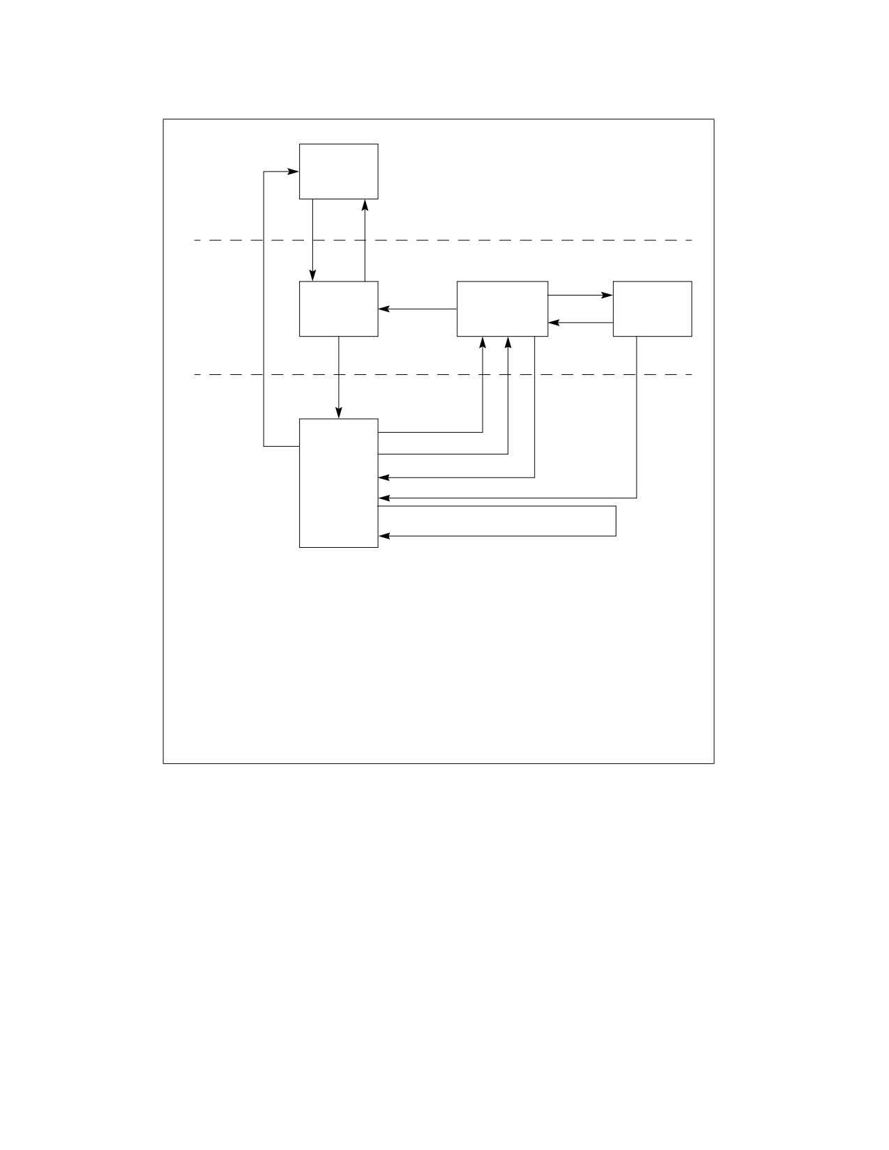
Figure 21-3 summarizes the methods of entering and leaving virtual-8086 mode. The processor switches to
virtual-8086 mode in either of the following situations:
• Task switch when the VM flag is set to 1 in the EFLAGS register image stored in the TSS for the task. Here the
task switch can be initiated in either of two ways:
— A CALL or JMP instruction.
— An IRET instruction, where the NT flag in the EFLAGS image is set to 1.
• Return from a protected-mode interrupt or exception handler when the VM flag is set to 1 in the EFLAGS
register image on the stack.
When a task switch is used to enter virtual-8086 mode, the TSS for the virtual-8086-mode task must be a 32-bit
TSS. (If the new TSS is a 16-bit TSS, the upper word of the EFLAGS register is not in the TSS, causing the processor
to clear the VM flag when it loads the EFLAGS register.) The processor updates the VM flag prior to loading the
segment registers from their images in the new TSS. The new setting of the VM flag determines whether the
processor interprets the contents of the segment registers as 8086-style segment selectors or protected-mode
segment selectors. When the VM flag is set, the segment registers are loaded from the TSS, using 8086-style
address translation to form base addresses.
See Section 21.3, “Interrupt and Exception Handling in Virtual-8086 Mode,” for information on entering virtual-
8086 mode on a return from an interrupt or exception handler.
21-8
Vol. 3B
8086 EMULATION
Real Mode
Code
Real-Address
Mode
PE=0 or
PE=1
RESET
Task Switch
Protected-
CALL
Protected
Protected-
VM=0
Mode Interrupt
Virtual-8086
Mode
Mode Tasks
and Exception
Monitor
Handlers
RET
Task Switch1
VM = 0
VM = 1
Interrupt or
Exception2
Virtual-8086
Mode
Virtual-8086
#GP Exception3
RESET
Mode Tasks
(8086
IRET4
Programs)
IRET5
Redirect Interrupt to 8086 Program
Interrupt or Exception Handler6
NOTES:
1. Task switch carried out in either of two ways:
- CALL or JMP where the VM flag in the EFLAGS image is 1.
- IRET where VM is 1 and NT is 1.
2. Hardware interrupt or exception; software interrupt (INT n) when IOPL is 3.
3. General-protection exception caused by software interrupt (INT n), IRET,
POPF, PUSHF, IN, or OUT when IOPL is less than 3.
4. Normal return from protected-mode interrupt or exception handler.
5. A return from the 8086 monitor to redirect an interrupt or exception back
to an interrupt or exception handler in the 8086 program running in virtual-
8086 mode.
6. Internal redirection of a software interrupt (INT n) when VME is 1,
IOPL is <3, and the redirection bit is 1.
Figure 21-3. Entering and Leaving Virtual-8086 Mode
21.2.6 Leaving Virtual-8086 Mode
The processor can leave the virtual-8086 mode only through an interrupt or exception. The following are situations
where an interrupt or exception will lead to the processor leaving virtual-8086 mode (see Figure 21-3):
• The processor services a hardware interrupt generated to signal the suspension of execution of the virtual-
8086 application. This hardware interrupt may be generated by a timer or other external mechanism. Upon
receiving the hardware interrupt, the processor enters protected mode and switches to a protected-mode (or
another virtual-8086 mode) task either through a task gate in the protected-mode IDT or through a trap or
interrupt gate that points to a handler that initiates a task switch. A task switch from a virtual-8086 task to
another task loads the EFLAGS register from the TSS of the new task. The value of the VM flag in the new
EFLAGS determines if the new task executes in virtual-8086 mode or not.
• The processor services an exception caused by code executing the virtual-8086 task or services a hardware
interrupt that “belongs to” the virtual-8086 task. Here, the processor enters protected mode and services the
Vol. 3B
21-9
8086 EMULATION
exception or hardware interrupt through the protected-mode IDT (normally through an interrupt or trap gate)
and the protected-mode exception- and interrupt-handlers. The processor may handle the exception or
interrupt within the context of the virtual 8086 task and return to virtual-8086 mode on a return from the
handler procedure. The processor may also execute a task switch and handle the exception or interrupt in the
context of another task.
• The processor services a software interrupt generated by code executing in the virtual-8086 task (such as a
software interrupt to call a MS-DOS* operating system routine). The processor provides several methods of
handling these software interrupts, which are discussed in detail in Section 21.3.3, “Class 3—Software
Interrupt Handling in Virtual-8086 Mode.” Most of them involve the processor entering protected mode, often
by means of a general-protection (#GP) exception. In protected mode, the processor can send the interrupt to
the virtual-8086 monitor for handling and/or redirect the interrupt back to the application program running in
virtual-8086 mode task for handling.
IA-32 processors that incorporate the virtual mode extension (enabled with the VME flag in control register
CR4) are capable of redirecting software-generated interrupts back to the program’s interrupt handlers without
leaving virtual-8086 mode. See Section 21.3.3.4, “Method 5: Software Interrupt Handling,” for more
information on this mechanism.
• A hardware reset initiated by asserting the RESET or INIT pin is a special kind of interrupt. When a RESET or
INIT is signaled while the processor is in virtual-8086 mode, the processor leaves virtual-8086 mode and enters
real-address mode.
• Execution of the HLT instruction in virtual-8086 mode will cause a general-protection (GP#) fault, which the
protected-mode handler generally sends to the virtual-8086 monitor. The virtual-8086 monitor then
determines the correct execution sequence after verifying that it was entered as a result of a HLT execution.
See Section 21.3, “Interrupt and Exception Handling in Virtual-8086 Mode,” for information on leaving virtual-8086
mode to handle an interrupt or exception generated in virtual-8086 mode.
21.2.7 Sensitive Instructions
When an IA-32 processor is running in virtual-8086 mode, the CLI, STI, PUSHF, POPF, INT n, and IRET instructions
are sensitive to IOPL. The IN, INS, OUT, and OUTS instructions, which are sensitive to IOPL in protected mode, are
not sensitive in virtual-8086 mode.
The CPL is always 3 while running in virtual-8086 mode; if the IOPL is less than 3, an attempt to use the IOPL-sensi-
tive instructions listed above triggers a general-protection exception (#GP). These instructions are sensitive to
IOPL to give the virtual-8086 monitor a chance to emulate the facilities they affect.
21.2.8 Virtual-8086 Mode I/O
Many 8086 programs written for non-multitasking systems directly access I/O ports. This practice may cause prob-
lems in a multitasking environment. If more than one program accesses the same port, they may interfere with
each other. Most multitasking systems require application programs to access I/O ports through the operating
system. This results in simplified, centralized control.
The processor provides I/O protection for creating I/O that is compatible with the environment and transparent to
8086 programs. Designers may take any of several possible approaches to protecting I/O ports:
• Protect the I/O address space and generate exceptions for all attempts to perform I/O directly.
• Let the 8086 program perform I/O directly.
• Generate exceptions on attempts to access specific I/O ports.
• Generate exceptions on attempts to access specific memory-mapped I/O ports.
The method of controlling access to I/O ports depends upon whether they are I/O-port mapped or memory
mapped.
21-10
Vol. 3B

8086 EMULATION
21.2.8.1 I/O-Port-Mapped I/O
The I/O permission bit map in the TSS can be used to generate exceptions on attempts to access specific I/O port
addresses. The I/O permission bit map of each virtual-8086-mode task determines which I/O addresses generate
exceptions for that task. Because each task may have a different I/O permission bit map, the addresses that
generate exceptions for one task may be different from the addresses for another task. This differs from protected
mode in which, if the CPL is less than or equal to the IOPL, I/O access is allowed without checking the I/O permis-
sion bit map. See Chapter 19, “Input/Output,” in the Intel® 64 and IA-32 Architectures Software Developer’s
Manual, Volume 1, for more information about the I/O permission bit map.
21.2.8.2 Memory-Mapped I/O
In systems which use memory-mapped I/O, the paging facilities of the processor can be used to generate excep-
tions for attempts to access I/O ports. The virtual-8086 monitor may use paging to control memory-mapped I/O in
these ways:
• Map part of the linear address space of each task that needs to perform I/O to the physical address space
where I/O ports are placed. By putting the I/O ports at different addresses (in different pages), the paging
mechanism can enforce isolation between tasks.
• Map part of the linear address space to pages that are not-present. This generates an exception whenever a
task attempts to perform I/O to those pages. System software then can interpret the I/O operation being
attempted.
Software emulation of the I/O space may require too much operating system intervention under some conditions.
In these cases, it may be possible to generate an exception for only the first attempt to access I/O. The system
software then may determine whether a program can be given exclusive control of I/O temporarily, the protection
of the I/O space may be lifted, and the program allowed to run at full speed.
21.2.8.3 Special I/O Buffers
Buffers of intelligent controllers (for example, a bit-mapped frame buffer) also can be emulated using page
mapping. The linear space for the buffer can be mapped to a different physical space for each virtual-8086-mode
task. The virtual-8086 monitor then can control which virtual buffer to copy onto the real buffer in the physical
address space.
21.3
INTERRUPT AND EXCEPTION HANDLING IN VIRTUAL-8086 MODE
When the processor receives an interrupt or detects an exception condition while in virtual-8086 mode, it invokes
an interrupt or exception handler, just as it does in protected or real-address mode. The interrupt or exception
handler that is invoked and the mechanism used to invoke it depends on the class of interrupt or exception that has
been detected or generated and the state of various system flags and fields.
In virtual-8086 mode, the interrupts and exceptions are divided into three classes for the purposes of handling:
• Class 1 — All processor-generated exceptions and all hardware interrupts, including the NMI interrupt and the
hardware interrupts sent to the processor’s external interrupt delivery pins. All class 1 exceptions and
interrupts are handled by the protected-mode exception and interrupt handlers.
• Class 2 — Special case for maskable hardware interrupts (Section 6.3.2, “Maskable Hardware Interrupts”)
when the virtual mode extensions are enabled.
• Class 3 — All software-generated interrupts, that is interrupts generated with the INT n instruction1.
The method the processor uses to handle class 2 and 3 interrupts depends on the setting of the following flags and
fields:
• IOPL field (bits 12 and 13 in the EFLAGS register) — Controls how class 3 software interrupts are handled
when the processor is in virtual-8086 mode (see Section 2.3, “System Flags and Fields in the EFLAGS
1. The INT 3 instruction is a special case (see the description of the INT n instruction in Chapter 3, “Instruction Set Reference, A-L,” of
the Intel® 64 and IA-32 Architectures Software Developer’s Manual, Volume 2A).
Vol. 3B
21-11
8086 EMULATION
Register”). This field also controls the enabling of the VIF and VIP flags in the EFLAGS register when the VME
flag is set. The VIF and VIP flags are provided to assist in the handling of class 2 maskable hardware interrupts.
• VME flag (bit 0 in control register CR4) — Enables the virtual mode extension for the processor when set
(see Section 2.5, “Control Registers”).
• Software interrupt redirection bit map (32 bytes in the TSS, see Figure 21-5) — Contains 256 flags
that indicates how class 3 software interrupts should be handled when they occur in virtual-8086 mode. A
software interrupt can be directed either to the interrupt and exception handlers in the currently running 8086
program or to the protected-mode interrupt and exception handlers.
• The virtual interrupt flag (VIF) and virtual interrupt pending flag (VIP) in the EFLAGS register —
Provides virtual interrupt support for the handling of class 2 maskable hardware interrupts (see Section
21.3.2, “Class 2—Maskable Hardware Interrupt Handling in Virtual-8086 Mode Using the Virtual Interrupt
Mechanism”).
NOTE
The VME flag, software interrupt redirection bit map, and VIF and VIP flags are only available in
IA-32 processors that support the virtual mode extensions. These extensions were introduced in
the IA-32 architecture with the Pentium processor.
The following sections describe the actions that processor takes and the possible actions of interrupt and exception
handlers for the two classes of interrupts described in the previous paragraphs. These sections describe three
possible types of interrupt and exception handlers:
• Protected-mode interrupt and exceptions handlers — These are the standard handlers that the processor
calls through the protected-mode IDT.
• Virtual-8086 monitor interrupt and exception handlers — These handlers are resident in the virtual-8086
monitor, and they are commonly accessed through a general-protection exception (#GP, interrupt 13) that is
directed to the protected-mode general-protection exception handler.
•
8086 program interrupt and exception handlers — These handlers are part of the 8086 program that is
running in virtual-8086 mode.
The following sections describe how these handlers are used, depending on the selected class and method of inter-
rupt and exception handling.
21.3.1 Class 1—Hardware Interrupt and Exception Handling in Virtual-8086 Mode
In virtual-8086 mode, the Pentium, P6 family, Pentium 4, and Intel Xeon processors handle hardware interrupts
and exceptions in the same manner as they are handled by the Intel486 and Intel386 processors. They invoke the
protected-mode interrupt or exception handler that the interrupt or exception vector points to in the IDT. Here, the
IDT entry must contain either a 32-bit trap or interrupt gate or a task gate. The following sections describe various
ways that a virtual-8086 mode interrupt or exception can be handled after the protected-mode handler has been
invoked.
See Section 21.3.2, “Class 2—Maskable Hardware Interrupt Handling in Virtual-8086 Mode Using the Virtual Inter-
rupt Mechanism,” for a description of the virtual interrupt mechanism that is available for handling maskable hard-
ware interrupts while in virtual-8086 mode. When this mechanism is either not available or not enabled, maskable
hardware interrupts are handled in the same manner as exceptions, as described in the following sections.
21.3.1.1 Handling an Interrupt or Exception Through a Protected-Mode Trap or Interrupt Gate
When an interrupt or exception vector points to a 32-bit trap or interrupt gate in the IDT, the gate must in turn point
to a nonconforming, privilege-level 0, code segment. When accessing this code segment, processor performs the
following steps.
1. Switches to 32-bit protected mode and privilege level 0.
2. Saves the state of the processor on the privilege-level 0 stack. The states of the EIP, CS, EFLAGS, ESP, SS, ES,
DS, FS, and GS registers are saved (see Figure 21-4).
21-12
Vol. 3B
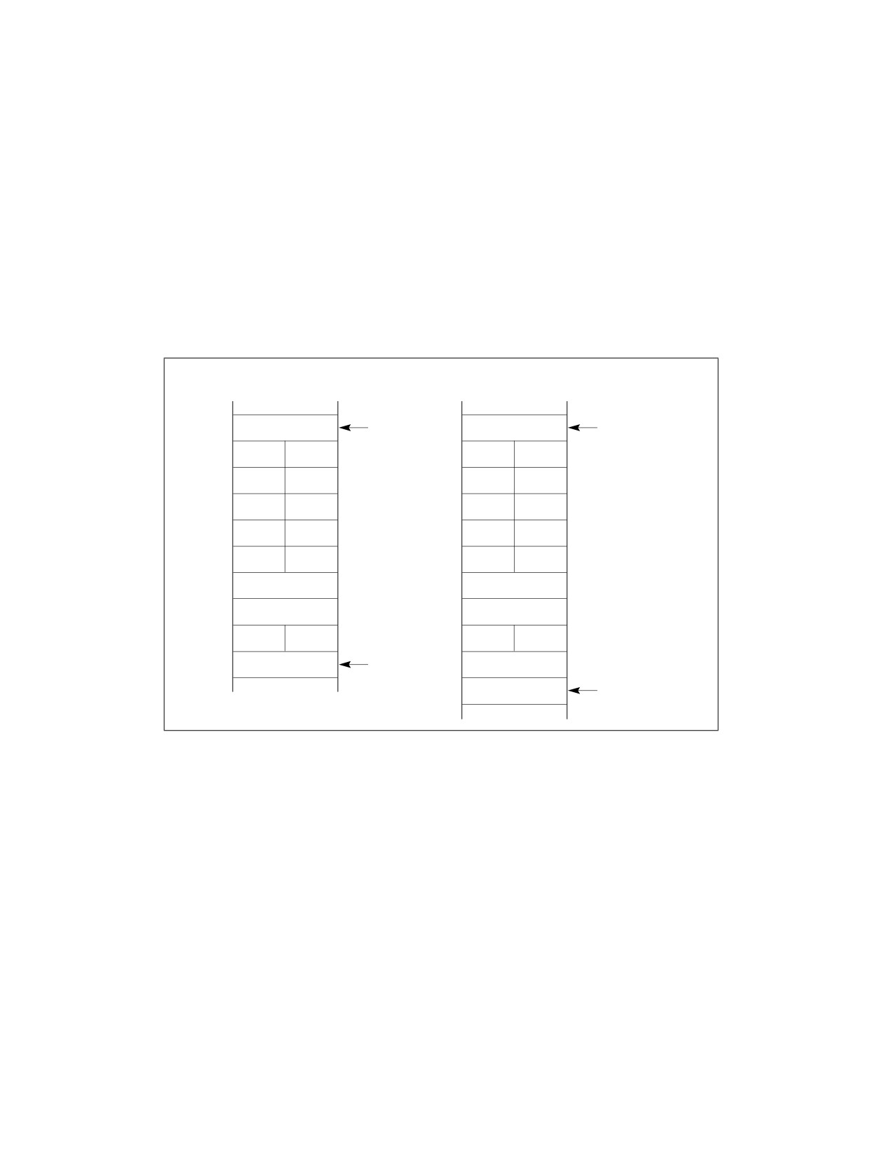
8086 EMULATION
3. Clears the segment registers. Saving the DS, ES, FS, and GS registers on the stack and then clearing the
registers lets the interrupt or exception handler safely save and restore these registers regardless of the type
segment selectors they contain (protected-mode or 8086-style). The interrupt and exception handlers, which
may be called in the context of either a protected-mode task or a virtual-8086-mode task, can use the same
code sequences for saving and restoring the registers for any task. Clearing these registers before execution of
the IRET instruction does not cause a trap in the interrupt handler. Interrupt procedures that expect values in
the segment registers or that return values in the segment registers must use the register images saved on the
stack for privilege level 0.
4. Clears VM, NT, RF, and TF flags (in the EFLAGS register). If the gate is an interrupt gate, clears the IF flag.
5. Begins executing the selected interrupt or exception handler.
If the trap or interrupt gate references a procedure in a conforming segment or in a segment at a privilege level
other than 0, the processor generates a general-protection exception (#GP). Here, the error code is the segment
selector of the code segment to which a call was attempted.
Without Error Code
With Error Code
ESP from
ESP from
Unused
Unused
TSS
TSS
Old GS
Old GS
Old FS
Old FS
Old DS
Old DS
Old ES
Old ES
Old SS
Old SS
Old ESP
Old ESP
Old EFLAGS
Old EFLAGS
Old CS
Old CS
Old EIP
New ESP
Old EIP
Error Code
New ESP
Figure 21-4. Privilege Level 0 Stack After Interrupt or Exception in Virtual-8086 Mode
Interrupt and exception handlers can examine the VM flag on the stack to determine if the interrupted procedure
was running in virtual-8086 mode. If so, the interrupt or exception can be handled in one of three ways:
• The protected-mode interrupt or exception handler that was called can handle the interrupt or exception.
• The protected-mode interrupt or exception handler can call the virtual-8086 monitor to handle the interrupt or
exception.
• The virtual-8086 monitor (if called) can in turn pass control back to the 8086 program’s interrupt and exception
handler.
If the interrupt or exception is handled with a protected-mode handler, the handler can return to the interrupted
program in virtual-8086 mode by executing an IRET instruction. This instruction loads the EFLAGS and segment
registers from the images saved in the privilege level 0 stack (see Figure 21-4). A set VM flag in the EFLAGS image
causes the processor to switch back to virtual-8086 mode. The CPL at the time the IRET instruction is executed
must be 0, otherwise the processor does not change the state of the VM flag.
The virtual-8086 monitor runs at privilege level 0, like the protected-mode interrupt and exception handlers. It is
commonly closely tied to the protected-mode general-protection exception (#GP, vector 13) handler. If the
Vol. 3B
21-13
8086 EMULATION
protected-mode interrupt or exception handler calls the virtual-8086 monitor to handle the interrupt or exception,
the return from the virtual-8086 monitor to the interrupted virtual-8086 mode program requires two return
instructions: a RET instruction to return to the protected-mode handler and an IRET instruction to return to the
interrupted program.
The virtual-8086 monitor has the option of directing the interrupt and exception back to an interrupt or exception
handler that is part of the interrupted 8086 program, as described in Section 21.3.1.2, “Handling an Interrupt or
Exception With an 8086 Program Interrupt or Exception Handler.”
21.3.1.2 Handling an Interrupt or Exception With an 8086 Program Interrupt or Exception Handler
Because it was designed to run on an 8086 processor, an 8086 program running in a virtual-8086-mode task
contains an 8086-style interrupt vector table, which starts at linear address 0. If the virtual-8086 monitor correctly
directs an interrupt or exception vector back to the virtual-8086-mode task it came from, the handlers in the 8086
program can handle the interrupt or exception. The virtual-8086 monitor must carry out the following steps to send
an interrupt or exception back to the 8086 program:
1. Use the 8086 interrupt vector to locate the appropriate handler procedure in the 8086 program interrupt table.
2. Store the EFLAGS (low-order 16 bits only), CS and EIP values of the 8086 program on the privilege-level 3
stack. This is the stack that the virtual-8086-mode task is using. (The 8086 handler may use or modify this
information.)
3. Change the return link on the privilege-level 0 stack to point to the privilege-level 3 handler procedure.
4. Execute an IRET instruction to pass control to the 8086 program handler.
5. When the IRET instruction from the privilege-level 3 handler triggers a general-protection exception (#GP) and
thus effectively again calls the virtual-8086 monitor, restore the return link on the privilege-level 0 stack to
point to the original, interrupted, privilege-level 3 procedure.
6. Copy the low order 16 bits of the EFLAGS image from the privilege-level 3 stack to the privilege-level 0 stack
(because some 8086 handlers modify these flags to return information to the code that caused the interrupt).
7. Execute an IRET instruction to pass control back to the interrupted 8086 program.
Note that if an operating system intends to support all 8086 MS-DOS-based programs, it is necessary to use the
actual 8086 interrupt and exception handlers supplied with the program. The reason for this is that some programs
modify their own interrupt vector table to substitute (or hook in series) their own specialized interrupt and excep-
tion handlers.
21.3.1.3 Handling an Interrupt or Exception Through a Task Gate
When an interrupt or exception vector points to a task gate in the IDT, the processor performs a task switch to the
selected interrupt- or exception-handling task. The following actions are carried out as part of this task switch:
1. The EFLAGS register with the VM flag set is saved in the current TSS.
2. The link field in the TSS of the called task is loaded with the segment selector of the TSS for the interrupted
virtual-8086-mode task.
3. The EFLAGS register is loaded from the image in the new TSS, which clears the VM flag and causes the
processor to switch to protected mode.
4. The NT flag in the EFLAGS register is set.
5. The processor begins executing the selected interrupt- or exception-handler task.
When an IRET instruction is executed in the handler task and the NT flag in the EFLAGS register is set, the proces-
sors switches from a protected-mode interrupt- or exception-handler task back to a virtual-8086-mode task. Here,
the EFLAGS and segment registers are loaded from images saved in the TSS for the virtual-8086-mode task. If the
VM flag is set in the EFLAGS image, the processor switches back to virtual-8086 mode on the task switch. The CPL
at the time the IRET instruction is executed must be 0, otherwise the processor does not change the state of the
VM flag.
21-14
Vol. 3B
8086 EMULATION
21.3.2 Class 2—Maskable Hardware Interrupt Handling in Virtual-8086 Mode Using the
Virtual Interrupt Mechanism
Maskable hardware interrupts are those interrupts that are delivered through the INTR# pin or through an inter-
rupt request to the local APIC (see Section 6.3.2, “Maskable Hardware Interrupts”). These interrupts can be inhib-
ited (masked) from interrupting an executing program or task by clearing the IF flag in the EFLAGS register.
When the VME flag in control register CR4 is set and the IOPL field in the EFLAGS register is less than 3, two addi-
tional flags are activated in the EFLAGS register:
• VIF (virtual interrupt) flag, bit 19 of the EFLAGS register.
• VIP (virtual interrupt pending) flag, bit 20 of the EFLAGS register.
These flags provide the virtual-8086 monitor with more efficient control over handling maskable hardware inter-
rupts that occur during virtual-8086 mode tasks. They also reduce interrupt-handling overhead, by eliminating the
need for all IF related operations (such as PUSHF, POPF, CLI, and STI instructions) to trap to the virtual-8086
monitor. The purpose and use of these flags are as follows.
NOTE
The VIF and VIP flags are only available in IA-32 processors that support the virtual mode
extensions. These extensions were introduced in the IA-32 architecture with the Pentium
processor. When this mechanism is either not available or not enabled, maskable hardware
interrupts are handled as class 1 interrupts. Here, if VIF and VIP flags are needed, the virtual-8086
monitor can implement them in software.
Existing 8086 programs commonly set and clear the IF flag in the EFLAGS register to enable and disable maskable
hardware interrupts, respectively; for example, to disable interrupts while handling another interrupt or an excep-
tion. This practice works well in single task environments, but can cause problems in multitasking and multiple-
processor environments, where it is often desirable to prevent an application program from having direct control
over the handling of hardware interrupts. When using earlier IA-32 processors, this problem was often solved by
creating a virtual IF flag in software. The IA-32 processors (beginning with the Pentium processor) provide hard-
ware support for this virtual IF flag through the VIF and VIP flags.
The VIF flag is a virtualized version of the IF flag, which an application program running from within a virtual-8086
task can used to control the handling of maskable hardware interrupts. When the VIF flag is enabled, the CLI and
STI instructions operate on the VIF flag instead of the IF flag. When an 8086 program executes the CLI instruction,
the processor clears the VIF flag to request that the virtual-8086 monitor inhibit maskable hardware interrupts
from interrupting program execution; when it executes the STI instruction, the processor sets the VIF flag
requesting that the virtual-8086 monitor enable maskable hardware interrupts for the 8086 program. But actually
the IF flag, managed by the operating system, always controls whether maskable hardware interrupts are enabled.
Also, if under these circumstances an 8086 program tries to read or change the IF flag using the PUSHF or POPF
instructions, the processor will change the VIF flag instead, leaving IF unchanged.
The VIP flag provides software a means of recording the existence of a deferred (or pending) maskable hardware
interrupt. This flag is read by the processor but never explicitly written by the processor; it can only be written by
software.
If the IF flag is set and the VIF and VIP flags are enabled, and the processor receives a maskable hardware inter-
rupt (interrupt vector 0 through 255), the processor performs and the interrupt handler software should perform
the following operations:
1. The processor invokes the protected-mode interrupt handler for the interrupt received, as described in the
following steps. These steps are almost identical to those described for method 1 interrupt and exception
handling in Section 21.3.1.1, “Handling an Interrupt or Exception Through a Protected-Mode Trap or Interrupt
Gate”:
a. Switches to 32-bit protected mode and privilege level 0.
b. Saves the state of the processor on the privilege-level 0 stack. The states of the EIP, CS, EFLAGS, ESP, SS,
ES, DS, FS, and GS registers are saved (see Figure 21-4).
c. Clears the segment registers.
Vol. 3B
21-15
8086 EMULATION
d. Clears the VM flag in the EFLAGS register.
e. Begins executing the selected protected-mode interrupt handler.
2. The recommended action of the protected-mode interrupt handler is to read the VM flag from the EFLAGS
image on the stack. If this flag is set, the handler makes a call to the virtual-8086 monitor.
3. The virtual-8086 monitor should read the VIF flag in the EFLAGS register.
— If the VIF flag is clear, the virtual-8086 monitor sets the VIP flag in the EFLAGS image on the stack to
indicate that there is a deferred interrupt pending and returns to the protected-mode handler.
— If the VIF flag is set, the virtual-8086 monitor can handle the interrupt if it “belongs” to the 8086 program
running in the interrupted virtual-8086 task; otherwise, it can call the protected-mode interrupt handler to
handle the interrupt.
4. The protected-mode handler executes a return to the program executing in virtual-8086 mode.
5. Upon returning to virtual-8086 mode, the processor continues execution of the 8086 program.
When the 8086 program is ready to receive maskable hardware interrupts, it executes the STI instruction to set the
VIF flag (enabling maskable hardware interrupts). Prior to setting the VIF flag, the processor automatically checks
the VIP flag and does one of the following, depending on the state of the flag:
• If the VIP flag is clear (indicating no pending interrupts), the processor sets the VIF flag.
• If the VIP flag is set (indicating a pending interrupt), the processor generates a general-protection exception
(#GP).
The recommended action of the protected-mode general-protection exception handler is to then call the virtual-
8086 monitor and let it handle the pending interrupt. After handling the pending interrupt, the typical action of the
virtual-8086 monitor is to clear the VIP flag and set the VIF flag in the EFLAGS image on the stack, and then
execute a return to the virtual-8086 mode. The next time the processor receives a maskable hardware interrupt, it
will then handle it as described in steps 1 through 5 earlier in this section.
If the processor finds that both the VIF and VIP flags are set at the beginning of an instruction, it generates a
general-protection exception. This action allows the virtual-8086 monitor to handle the pending interrupt for the
virtual-8086 mode task for which the VIF flag is enabled. Note that this situation can only occur immediately
following execution of a POPF or IRET instruction or upon entering a virtual-8086 mode task through a task switch.
Note that the states of the VIF and VIP flags are not modified in real-address mode or during transitions between
real-address and protected modes.
NOTE
The virtual interrupt mechanism described in this section is also available for use in protected
mode, see Section 21.4, “Protected-Mode Virtual Interrupts.”
21.3.3 Class 3—Software Interrupt Handling in Virtual-8086 Mode
When the processor receives a software interrupt (an interrupt generated with the INT n instruction) while in
virtual-8086 mode, it can use any of six different methods to handle the interrupt. The method selected depends
on the settings of the VME flag in control register CR4, the IOPL field in the EFLAGS register, and the software inter-
rupt redirection bit map in the TSS. Table 21-2 lists the six methods of handling software interrupts in virtual-8086
mode and the respective settings of the VME flag, IOPL field, and the bits in the interrupt redirection bit map for
each method. The table also summarizes the various actions the processor takes for each method.
The VME flag enables the virtual mode extensions for the Pentium and later IA-32 processors. When this flag is
clear, the processor responds to interrupts and exceptions in virtual-8086 mode in the same manner as an Intel386
or Intel486 processor does. When this flag is set, the virtual mode extension provides the following enhancements
to virtual-8086 mode:
• Speeds up the handling of software-generated interrupts in virtual-8086 mode by allowing the processor to
bypass the virtual-8086 monitor and redirect software interrupts back to the interrupt handlers that are part of
the currently running 8086 program.
• Supports virtual interrupts for software written to run on the 8086 processor.
21-16
Vol. 3B

8086 EMULATION
The IOPL value interacts with the VME flag and the bits in the interrupt redirection bit map to determine how
specific software interrupts should be handled.
The software interrupt redirection bit map (see Figure 21-5) is a 32-byte field in the TSS. This map is located
directly below the I/O permission bit map in the TSS. Each bit in the interrupt redirection bit map is mapped to an
interrupt vector. Bit 0 in the interrupt redirection bit map (which maps to vector zero in the interrupt table) is
located at the I/O base map address in the TSS minus 32 bytes. When a bit in this bit map is set, it indicates that
the associated software interrupt (interrupt generated with an INT n instruction) should be handled through the
protected-mode IDT and interrupt and exception handlers. When a bit in this bit map is clear, the processor redi-
rects the associated software interrupt back to the interrupt table in the 8086 program (located at linear address 0
in the program’s address space).
NOTE
The software interrupt redirection bit map does not affect hardware generated interrupts and
exceptions. Hardware generated interrupts and exceptions are always handled by the protected-
mode interrupt and exception handlers.
Table 21-2. Software Interrupt Handling Methods While in Virtual-8086 Mode
Bit in
Redir.
Method
VME
IOPL
Bitmap*
Processor Action
1
0
3
X
Interrupt directed to a protected-mode interrupt handler:
• Switches to privilege-level 0 stack.
• Pushes GS, FS, DS, and ES onto privilege-level 0 stack.
• Pushes SS, ESP, EFLAGS, CS, and EIP of interrupted task onto privilege-level 0 stack.
• Clears VM, RF, NT, and TF flags.
• If serviced through interrupt gate, clears IF flag.
• Clears GS, FS, DS, and ES to 0.
• Sets CS and EIP from interrupt gate.
2
0
< 3
X
Interrupt directed to protected-mode general-protection exception (#GP) handler.
3
1
< 3
1
Interrupt directed to a protected-mode general-protection exception (#GP) handler; VIF and VIP
flag support for handling class 2 maskable hardware interrupts.
4
1
3
1
Interrupt directed to protected-mode interrupt handler: (see method 1 processor action).
5
1
3
0
Interrupt redirected to 8086 program interrupt handler:
• Pushes EFLAGS.
• Pushes CS and EIP (lower 16 bits only).
• Clears IF flag.
• Clears TF flag.
• Loads CS and EIP (lower 16 bits only) from selected entry in the interrupt vector table of the
current virtual-8086 task.
6
1
< 3
0
Interrupt redirected to 8086 program interrupt handler; VIF and VIP flag support for handling class
2 maskable hardware interrupts:
• Pushes EFLAGS with IOPL set to 3 and VIF copied to IF.
• Pushes CS and EIP (lower 16 bits only).
• Clears the VIF flag.
• Clears TF flag.
• Loads CS and EIP (lower 16 bits only) from selected entry in the interrupt vector table of the
current virtual-8086 task.
NOTE:
* When set to 0, software interrupt is redirected back to the 8086 program interrupt handler; when set to 1, interrupt is directed to
protected-mode handler.
Vol. 3B
21-17
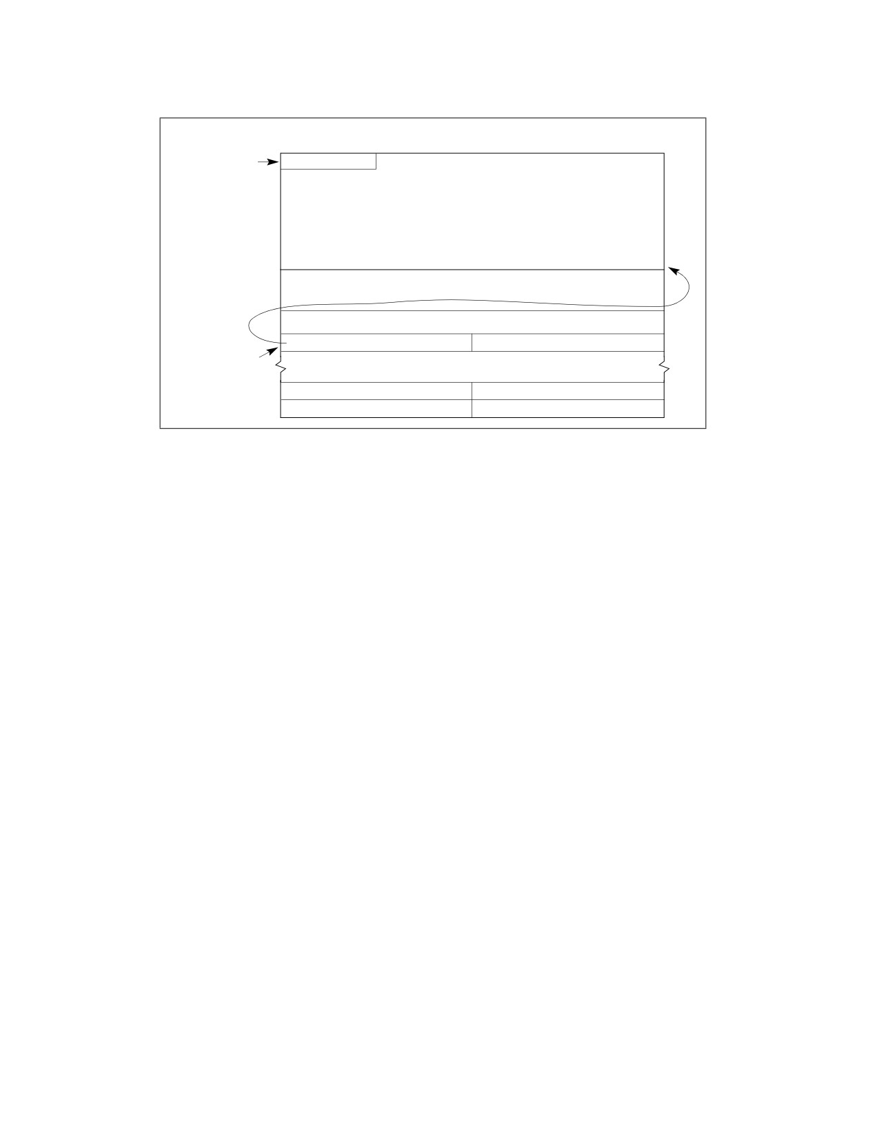
8086 EMULATION
31
24 23
Task-State Segment (TSS)
0
Last byte of
1
1
1
1
1
1
1
1
bit
map must be
I/O Permission Bit Map
Software Interrupt Redirection Bit Map (32 Bytes)
I/O Map Base
64H
I/O map
base must
not exceed
DFFFH.
0
Figure 21-5. Software Interrupt Redirection Bit Map in TSS
Redirecting software interrupts back to the 8086 program potentially speeds up interrupt handling because a
switch back and forth between virtual-8086 mode and protected mode is not required. This latter interrupt-
handling technique is particularly useful for 8086 operating systems (such as MS-DOS) that use the INT n instruc-
tion to call operating system procedures.
The CPUID instruction can be used to verify that the virtual mode extension is implemented on the processor. Bit 1
of the feature flags register (EDX) indicates the availability of the virtual mode extension (see “CPUID—CPU Iden-
tification” in Chapter 3, “Instruction Set Reference, A-L,” of the Intel® 64 and IA-32 Architectures Software Devel-
oper’s Manual, Volume 2A).
The following sections describe the six methods (or mechanisms) for handling software interrupts in virtual-8086
mode. See Section 21.3.2, “Class 2—Maskable Hardware Interrupt Handling in Virtual-8086 Mode Using the Virtual
Interrupt Mechanism,” for a description of the use of the VIF and VIP flags in the EFLAGS register for handling
maskable hardware interrupts.
21.3.3.1 Method 1: Software Interrupt Handling
When the VME flag in control register CR4 is clear and the IOPL field is 3, a Pentium or later IA-32 processor
handles software interrupts in the same manner as they are handled by an Intel386 or Intel486 processor. It
executes an implicit call to the interrupt handler in the protected-mode IDT pointed to by the interrupt vector. See
Section 21.3.1, “Class 1—Hardware Interrupt and Exception Handling in Virtual-8086 Mode,” for a complete
description of this mechanism and its possible uses.
21.3.3.2 Methods 2 and 3: Software Interrupt Handling
When a software interrupt occurs in virtual-8086 mode and the method 2 or 3 conditions are present, the processor
generates a general-protection exception (#GP). Method 2 is enabled when the VME flag is set to 0 and the IOPL
value is less than 3. Here the IOPL value is used to bypass the protected-mode interrupt handlers and cause any
software interrupt that occurs in virtual-8086 mode to be treated as a protected-mode general-protection excep-
tion (#GP). The general-protection exception handler calls the virtual-8086 monitor, which can then emulate an
8086-program interrupt handler or pass control back to the 8086 program’s handler, as described in Section
21.3.1.2, “Handling an Interrupt or Exception With an 8086 Program Interrupt or Exception Handler.”
Method 3 is enabled when the VME flag is set to 1, the IOPL value is less than 3, and the corresponding bit for the
software interrupt in the software interrupt redirection bit map is set to 1. Here, the processor performs the same
21-18
Vol. 3B
8086 EMULATION
operation as it does for method 2 software interrupt handling. If the corresponding bit for the software interrupt in
the software interrupt redirection bit map is set to 0, the interrupt is handled using method 6 (see Section 21.3.3.5,
“Method 6: Software Interrupt Handling”).
21.3.3.3 Method 4: Software Interrupt Handling
Method 4 handling is enabled when the VME flag is set to 1, the IOPL value is 3, and the bit for the interrupt vector
in the redirection bit map is set to 1. Method 4 software interrupt handling allows method 1 style handling when the
virtual mode extension is enabled; that is, the interrupt is directed to a protected-mode handler (see Section
21.3.3.1, “Method 1: Software Interrupt Handling”).
21.3.3.4 Method 5: Software Interrupt Handling
Method 5 software interrupt handling provides a streamlined method of redirecting software interrupts (invoked
with the INT n instruction) that occur in virtual 8086 mode back to the 8086 program’s interrupt vector table and
its interrupt handlers. Method 5 handling is enabled when the VME flag is set to 1, the IOPL value is 3, and the bit
for the interrupt vector in the redirection bit map is set to 0. The processor performs the following actions to make
an implicit call to the selected 8086 program interrupt handler:
1. Pushes the low-order 16 bits of the EFLAGS register onto the stack.
2. Pushes the current values of the CS and EIP registers onto the current stack. (Only the 16 least-significant bits
of the EIP register are pushed and no stack switch occurs.)
3. Clears the IF flag in the EFLAGS register to disable interrupts.
4. Clears the TF flag, in the EFLAGS register.
5. Locates the 8086 program interrupt vector table at linear address 0 for the 8086-mode task.
6. Loads the CS and EIP registers with values from the interrupt vector table entry pointed to by the interrupt
vector number. Only the 16 low-order bits of the EIP are loaded and the 16 high-order bits are set to 0. The
interrupt vector table is assumed to be at linear address 0 of the current virtual-8086 task.
7. Begins executing the selected interrupt handler.
An IRET instruction at the end of the handler procedure reverses these steps to return program control to the inter-
rupted 8086 program.
Note that with method 5 handling, a mode switch from virtual-8086 mode to protected mode does not occur. The
processor remains in virtual-8086 mode throughout the interrupt-handling operation.
The method 5 handling actions are virtually identical to the actions the processor takes when handling software
interrupts in real-address mode. The benefit of using method 5 handling to access the 8086 program handlers is
that it avoids the overhead of methods 2 and 3 handling, which requires first going to the virtual-8086 monitor,
then to the 8086 program handler, then back again to the virtual-8086 monitor, before returning to the interrupted
8086 program (see Section 21.3.1.2, “Handling an Interrupt or Exception With an 8086 Program Interrupt or
Exception Handler”).
NOTE
Methods 1 and 4 handling can handle a software interrupt in a virtual-8086 task with a regular
protected-mode handler, but this approach requires all virtual-8086 tasks to use the same software
interrupt handlers, which generally does not give sufficient latitude to the programs running in the
virtual-8086 tasks, particularly MS-DOS programs.
21.3.3.5 Method 6: Software Interrupt Handling
Method 6 handling is enabled when the VME flag is set to 1, the IOPL value is less than 3, and the bit for the inter-
rupt or exception vector in the redirection bit map is set to 0. With method 6 interrupt handling, software interrupts
are handled in the same manner as was described for method 5 handling (see Section 21.3.3.4, “Method 5: Soft-
ware Interrupt Handling”).
Vol. 3B
21-19
8086 EMULATION
Method 6 differs from method 5 in that with the IOPL value set to less than 3, the VIF and VIP flags in the EFLAGS
register are enabled, providing virtual interrupt support for handling class 2 maskable hardware interrupts (see
Section 21.3.2, “Class 2—Maskable Hardware Interrupt Handling in Virtual-8086 Mode Using the Virtual Interrupt
Mechanism”). These flags provide the virtual-8086 monitor with an efficient means of handling maskable hardware
interrupts that occur during a virtual-8086 mode task. Also, because the IOPL value is less than 3 and the VIF flag
is enabled, the information pushed on the stack by the processor when invoking the interrupt handler is slightly
different between methods 5 and 6 (see Table 21-2).
21.4
PROTECTED-MODE VIRTUAL INTERRUPTS
The IA-32 processors (beginning with the Pentium processor) also support the VIF and VIP flags in the EFLAGS
register in protected mode by setting the PVI (protected-mode virtual interrupt) flag in the CR4 register. Setting the
PVI flag allows applications running at privilege level 3 to execute the CLI and STI instructions without causing a
general-protection exception (#GP) or affecting hardware interrupts.
When the PVI flag is set to 1, the CPL is 3, and the IOPL is less than 3, the STI and CLI instructions set and clear
the VIF flag in the EFLAGS register, leaving IF unaffected. In this mode of operation, an application running in
protected mode and at a CPL of 3 can inhibit interrupts in the same manner as is described in Section 21.3.2, “Class
2—Maskable Hardware Interrupt Handling in Virtual-8086 Mode Using the Virtual Interrupt Mechanism,” for a
virtual-8086 mode task. When the application executes the CLI instruction, the processor clears the VIF flag. If the
processor receives a maskable hardware interrupt, the processor invokes the protected-mode interrupt handler.
This handler checks the state of the VIF flag in the EFLAGS register. If the VIF flag is clear (indicating that the active
task does not want to have interrupts handled now), the handler sets the VIP flag in the EFLAGS image on the stack
and returns to the privilege-level 3 application, which continues program execution. When the application executes
a STI instruction to set the VIF flag, the processor automatically invokes the general-protection exception handler,
which can then handle the pending interrupt. After handing the pending interrupt, the handler typically sets the VIF
flag and clears the VIP flag in the EFLAGS image on the stack and executes a return to the application program. The
next time the processor receives a maskable hardware interrupt, the processor will handle it in the normal manner
for interrupts received while the processor is operating at a CPL of 3.
If the protected-mode virtual interrupt extension is enabled, CPL = 3, and the processor finds that both the VIF and
VIP flags are set at the beginning of an instruction, a general-protection exception is generated.
Because the protected-mode virtual interrupt extension changes only the treatment of EFLAGS.IF (by having CLI
and STI update EFLAGS.VIF instead), it affects only the masking of maskable hardware interrupts (interrupt
vectors 32 through 255). NMI interrupts and exceptions are handled in the normal manner.
(When protected-mode virtual interrupts are disabled (that is, when the PVI flag in control register CR4 is set to 0,
the CPL is less than 3, or the IOPL value is 3), then the CLI and STI instructions execute in a manner compatible
with the Intel486 processor. That is, if the CPL is greater (less privileged) than the I/O privilege level (IOPL), a
general-protection exception occurs. If the IOPL value is 3, CLI and STI clear or set the IF flag, respectively.)
PUSHF, POPF, IRET, and INT are executed like in the Intel486 processor, regardless of whether protected-mode
virtual interrupts are enabled.
It is only possible to enter virtual-8086 mode through a task switch or the execution of an IRET instruction, and it
is only possible to leave virtual-8086 mode by faulting to a protected-mode interrupt handler (typically the general-
protection exception handler, which in turn calls the virtual 8086-mode monitor). In both cases, the EFLAGS
register is saved and restored. This is not true, however, in protected mode when the PVI flag is set and the
processor is not in virtual-8086 mode. Here, it is possible to call a procedure at a different privilege level, in which
case the EFLAGS register is not saved or modified. However, the states of VIF and VIP flags are never examined by
the processor when the CPL is not 3.
21-20
Vol. 3B

CHAPTER 22
MIXING 16-BIT AND 32-BIT CODE
Program modules written to run on IA-32 processors can be either 16-bit modules or 32-bit modules. Table 22-1
shows the characteristic of 16-bit and 32-bit modules.
Table 22-1. Characteristics of 16-Bit and 32-Bit Program Modules
Characteristic
16-Bit Program Modules
32-Bit Program Modules
Segment Size
0 to 64 KBytes
0 to 4 GBytes
Operand Sizes
8 bits and 16 bits
8 bits and 32 bits
Pointer Offset Size (Address Size)
16 bits
32 bits
Stack Pointer Size
16 Bits
32 Bits
Control Transfers Allowed to Code Segments
16 Bits
32 Bits
of This Size
The IA-32 processors function most efficiently when executing 32-bit program modules. They can, however, also
execute 16-bit program modules, in any of the following ways:
• In real-address mode.
• In virtual-8086 mode.
• System management mode (SMM).
• As a protected-mode task, when the code, data, and stack segments for the task are all configured as a 16-bit
segments.
• By integrating 16-bit and 32-bit segments into a single protected-mode task.
• By integrating 16-bit operations into 32-bit code segments.
Real-address mode, virtual-8086 mode, and SMM are native 16-bit modes. A legacy program assembled and/or
compiled to run on an Intel 8086 or Intel 286 processor should run in real-address mode or virtual-8086 mode
without modification. Sixteen-bit program modules can also be written to run in real-address mode for handling
system initialization or to run in SMM for handling system management functions. See Chapter 21, “8086 Emula-
tion,” for detailed information on real-address mode and virtual-8086 mode; see Chapter 32, “System Manage-
ment Mode,” for information on SMM.
This chapter describes how to integrate 16-bit program modules with 32-bit program modules when operating in
protected mode and how to mix 16-bit and 32-bit code within 32-bit code segments.
22.1
DEFINING 16-BIT AND 32-BIT PROGRAM MODULES
The following IA-32 architecture mechanisms are used to distinguish between and support 16-bit and 32-bit
segments and operations:
• The D (default operand and address size) flag in code-segment descriptors.
• The B (default stack size) flag in stack-segment descriptors.
•
16-bit and 32-bit call gates, interrupt gates, and trap gates.
• Operand-size and address-size instruction prefixes.
•
16-bit and 32-bit general-purpose registers.
The D flag in a code-segment descriptor determines the default operand-size and address-size for the instructions
of a code segment. (In real-address mode and virtual-8086 mode, which do not use segment descriptors, the
default is 16 bits.) A code segment with its D flag set is a 32-bit segment; a code segment with its D flag clear is a
16-bit segment.
Vol. 3B
22-1
MIXING 16-BIT AND 32-BIT CODE
The B flag in the stack-segment descriptor specifies the size of stack pointer (the 32-bit ESP register or the 16-bit
SP register) used by the processor for implicit stack references. The B flag for all data descriptors also controls
upper address range for expand down segments.
When transferring program control to another code segment through a call gate, interrupt gate, or trap gate, the
operand size used during the transfer is determined by the type of gate used (16-bit or 32-bit), (not by the D-flag
or prefix of the transfer instruction). The gate type determines how return information is saved on the stack (or
stacks).
For most efficient and trouble-free operation of the processor, 32-bit programs or tasks should have the D flag in
the code-segment descriptor and the B flag in the stack-segment descriptor set, and 16-bit programs or tasks
should have these flags clear. Program control transfers from 16-bit segments to 32-bit segments (and vice versa)
are handled most efficiently through call, interrupt, or trap gates.
Instruction prefixes can be used to override the default operand size and address size of a code segment. These
prefixes can be used in real-address mode as well as in protected mode and virtual-8086 mode. An operand-size or
address-size prefix only changes the size for the duration of the instruction.
22.2
MIXING 16-BIT AND 32-BIT OPERATIONS WITHIN A CODE SEGMENT
The following two instruction prefixes allow mixing of 32-bit and 16-bit operations within one segment:
• The operand-size prefix (66H)
• The address-size prefix (67H)
These prefixes reverse the default size selected by the D flag in the code-segment descriptor. For example, the
processor can interpret the (MOV mem, reg) instruction in any of four ways:
• In a 32-bit code segment:
— Moves 32 bits from a 32-bit register to memory using a 32-bit effective address.
— If preceded by an operand-size prefix, moves 16 bits from a 16-bit register to memory using a 32-bit
effective address.
— If preceded by an address-size prefix, moves 32 bits from a 32-bit register to memory using a 16-bit
effective address.
— If preceded by both an address-size prefix and an operand-size prefix, moves 16 bits from a 16-bit register
to memory using a 16-bit effective address.
• In a 16-bit code segment:
— Moves 16 bits from a 16-bit register to memory using a 16-bit effective address.
— If preceded by an operand-size prefix, moves 32 bits from a 32-bit register to memory using a 16-bit
effective address.
— If preceded by an address-size prefix, moves 16 bits from a 16-bit register to memory using a 32-bit
effective address.
— If preceded by both an address-size prefix and an operand-size prefix, moves 32 bits from a 32-bit register
to memory using a 32-bit effective address.
The previous examples show that any instruction can generate any combination of operand size and address size
regardless of whether the instruction is in a 16- or 32-bit segment. The choice of the 16- or 32-bit default for a code
segment is normally based on the following criteria:
• Performance — Always use 32-bit code segments when possible. They run much faster than 16-bit code
segments on P6 family processors, and somewhat faster on earlier IA-32 processors.
• The operating system the code segment will be running on — If the operating system is a 16-bit
operating system, it may not support 32-bit program modules.
• Mode of operation — If the code segment is being designed to run in real-address mode, virtual-8086 mode,
or SMM, it must be a 16-bit code segment.
22-2
Vol. 3B
MIXING 16-BIT AND 32-BIT CODE
• Backward compatibility to earlier IA-32 processors — If a code segment must be able to run on an Intel
8086 or Intel 286 processor, it must be a 16-bit code segment.
22.3
SHARING DATA AMONG MIXED-SIZE CODE SEGMENTS
Data segments can be accessed from both 16-bit and 32-bit code segments. When a data segment that is larger
than 64 KBytes is to be shared among 16- and 32-bit code segments, the data that is to be accessed from the 16-
bit code segments must be located within the first 64 KBytes of the data segment. The reason for this is that 16-
bit pointers by definition can only point to the first 64 KBytes of a segment.
A stack that spans less than 64 KBytes can be shared by both 16- and 32-bit code segments. This class of stacks
includes:
• Stacks in expand-up segments with the G (granularity) and B (big) flags in the stack-segment descriptor clear.
• Stacks in expand-down segments with the G and B flags clear.
• Stacks in expand-up segments with the G flag set and the B flag clear and where the stack is contained
completely within the lower 64 KBytes. (Offsets greater than FFFFH can be used for data, other than the stack,
which is not shared.)
See Section 3.4.5, “Segment Descriptors,” for a description of the G and B flags and the expand-down stack type.
The B flag cannot, in general, be used to change the size of stack used by a 16-bit code segment. This flag controls
the size of the stack pointer only for implicit stack references such as those caused by interrupts, exceptions, and
the PUSH, POP, CALL, and RET instructions. It does not control explicit stack references, such as accesses to
parameters or local variables. A 16-bit code segment can use a 32-bit stack only if the code is modified so that all
explicit references to the stack are preceded by the 32-bit address-size prefix, causing those references to use 32-
bit addressing and explicit writes to the stack pointer are preceded by a 32-bit operand-size prefix.
In 32-bit, expand-down segments, all offsets may be greater than 64 KBytes; therefore, 16-bit code cannot use
this kind of stack segment unless the code segment is modified to use 32-bit addressing.
22.4
TRANSFERRING CONTROL AMONG MIXED-SIZE CODE SEGMENTS
There are three ways for a procedure in a 16-bit code segment to safely make a call to a 32-bit code segment:
• Make the call through a 32-bit call gate.
• Make a 16-bit call to a 32-bit interface procedure. The interface procedure then makes a 32-bit call to the
intended destination.
• Modify the 16-bit procedure, inserting an operand-size prefix before the call, to change it to a 32-bit call.
Likewise, there are three ways for procedure in a 32-bit code segment to safely make a call to a 16-bit code
segment:
• Make the call through a 16-bit call gate. Here, the EIP value at the CALL instruction cannot exceed FFFFH.
• Make a 32-bit call to a 16-bit interface procedure. The interface procedure then makes a 16-bit call to the
intended destination.
• Modify the 32-bit procedure, inserting an operand-size prefix before the call, changing it to a 16-bit call. Be
certain that the return offset does not exceed FFFFH.
These methods of transferring program control overcome the following architectural limitations imposed on calls
between 16-bit and 32-bit code segments:
• Pointers from 16-bit code segments (which by default can only be 16 bits) cannot be used to address data or
code located beyond FFFFH in a 32-bit segment.
• The operand-size attributes for a CALL and its companion RETURN instruction must be the same to maintain
stack coherency. This is also true for implicit calls to interrupt and exception handlers and their companion IRET
instructions.
• A 32-bit parameters (particularly a pointer parameter) greater than FFFFH cannot be squeezed into a 16-bit
parameter location on a stack.
Vol. 3B
22-3
MIXING 16-BIT AND 32-BIT CODE
• The size of the stack pointer (SP or ESP) changes when switching between 16-bit and 32-bit code segments.
These limitations are discussed in greater detail in the following sections.
22.4.1 Code-Segment Pointer Size
For control-transfer instructions that use a pointer to identify the next instruction (that is, those that do not use
gates), the operand-size attribute determines the size of the offset portion of the pointer. The implications of this
rule are as follows:
• A JMP, CALL, or RET instruction from a 32-bit segment to a 16-bit segment is always possible using a 32-bit
operand size, providing the 32-bit pointer does not exceed FFFFH.
• A JMP, CALL, or RET instruction from a 16-bit segment to a 32-bit segment cannot address a destination greater
than FFFFH, unless the instruction is given an operand-size prefix.
See Section 22.4.5, “Writing Interface Procedures,” for an interface procedure that can transfer program control
from 16-bit segments to destinations in 32-bit segments beyond FFFFH.
22.4.2 Stack Management for Control Transfer
Because the stack is managed differently for 16-bit procedure calls than for 32-bit calls, the operand-size attribute
of the RET instruction must match that of the CALL instruction (see Figure 22-1). On a 16-bit call, the processor
pushes the contents of the 16-bit IP register and (for calls between privilege levels) the 16-bit SP register. The
matching RET instruction must also use a 16-bit operand size to pop these 16-bit values from the stack into the 16-
bit registers.
A 32-bit CALL instruction pushes the contents of the 32-bit EIP register and (for inter-privilege-level calls) the 32-
bit ESP register. Here, the matching RET instruction must use a 32-bit operand size to pop these 32-bit values from
the stack into the 32-bit registers. If the two parts of a CALL/RET instruction pair do not have matching operand
sizes, the stack will not be managed correctly and the values of the instruction pointer and stack pointer will not be
restored to correct values.
22-4
Vol. 3B
MIXING 16-BIT AND 32-BIT CODE
Without Privilege Transition
After 16-bit Call
After 32-bit Call
31
0
31
0
PARM 2
PARM 1
PARM 2
Stack
Growth
CS
IP
SP
PARM 1
CS
EIP
ESP
With Privilege Transition
After 16-bit Call
After 32-bit Call
31
0
31
0
SS
SP
SS
PARM 2
PARM 1
ESP
Stack
Growth
CS
IP
SP
PARM 2
PARM 1
CS
EIP
ESP
Undefined
Figure 22-1. Stack after Far 16- and 32-Bit Calls
While executing 32-bit code, if a call is made to a 16-bit code segment which is at the same or a more privileged
level (that is, the DPL of the called code segment is less than or equal to the CPL of the calling code segment)
through a 16-bit call gate, then the upper 16-bits of the ESP register may be unreliable upon returning to the 32-
bit code segment (that is, after executing a RET in the 16-bit code segment).
When the CALL instruction and its matching RET instruction are in code segments that have D flags with the same
values (that is, both are 32-bit code segments or both are 16-bit code segments), the default settings may be
used. When the CALL instruction and its matching RET instruction are in segments which have different D-flag
settings, an operand-size prefix must be used.
22.4.2.1 Controlling the Operand-Size Attribute For a Call
Three things can determine the operand-size of a call:
• The D flag in the segment descriptor for the calling code segment.
• An operand-size instruction prefix.
• The type of call gate (16-bit or 32-bit), if a call is made through a call gate.
When a call is made with a pointer (rather than a call gate), the D flag for the calling code segment determines the
operand-size for the CALL instruction. This operand-size attribute can be overridden by prepending an operand-
size prefix to the CALL instruction. So, for example, if the D flag for a code segment is set for 16 bits and the
operand-size prefix is used with a CALL instruction, the processor will cause the information stored on the stack to
Vol. 3B
22-5
MIXING 16-BIT AND 32-BIT CODE
be stored in 32-bit format. If the call is to a 32-bit code segment, the instructions in that code segment will be able
to read the stack coherently. Also, a RET instruction from the 32-bit code segment without an operand-size prefix
will maintain stack coherency with the 16-bit code segment being returned to.
When a CALL instruction references a call-gate descriptor, the type of call is determined by the type of call gate (16-
bit or 32-bit). The offset to the destination in the code segment being called is taken from the gate descriptor;
therefore, if a 32-bit call gate is used, a procedure in a 16-bit code segment can call a procedure located more than
64 KBytes from the base of a 32-bit code segment, because a 32-bit call gate uses a 32-bit offset.
Note that regardless of the operand size of the call and how it is determined, the size of the stack pointer used (SP
or ESP) is always controlled by the B flag in the stack-segment descriptor currently in use (that is, when B is clear,
SP is used, and when B is set, ESP is used).
An unmodified 16-bit code segment that has run successfully on an 8086 processor or in real-mode on a later IA-
32 architecture processor will have its D flag clear and will not use operand-size override prefixes. As a result, all
CALL instructions in this code segment will use the 16-bit operand-size attribute. Procedures in these code
segments can be modified to safely call procedures to 32-bit code segments in either of two ways:
• Relink the CALL instruction to point to 32-bit call gates (see Section 22.4.2.2, “Passing Parameters With a
Gate”).
• Add a 32-bit operand-size prefix to each CALL instruction.
22.4.2.2 Passing Parameters With a Gate
When referencing 32-bit gates with 16-bit procedures, it is important to consider the number of parameters passed
in each procedure call. The count field of the gate descriptor specifies the size of the parameter string to copy from
the current stack to the stack of a more privileged (numerically lower privilege level) procedure. The count field of
a 16-bit gate specifies the number of 16-bit words to be copied, whereas the count field of a 32-bit gate specifies
the number of 32-bit doublewords to be copied. The count field for a 32-bit gate must thus be half the size of the
number of words being placed on the stack by a 16-bit procedure. Also, the 16-bit procedure must use an even
number of words as parameters.
22.4.3 Interrupt Control Transfers
A program-control transfer caused by an exception or interrupt is always carried out through an interrupt or trap
gate (located in the IDT). Here, the type of the gate (16-bit or 32-bit) determines the operand-size attribute used
in the implicit call to the exception or interrupt handler procedure in another code segment.
A 32-bit interrupt or trap gate provides a safe interface to a 32-bit exception or interrupt handler when the excep-
tion or interrupt occurs in either a 32-bit or a 16-bit code segment. It is sometimes impractical, however, to place
exception or interrupt handlers in 16-bit code segments, because only 16-bit return addresses are saved on the
stack. If an exception or interrupt occurs in a 32-bit code segment when the EIP was greater than FFFFH, the 16-
bit handler procedure cannot provide the correct return address.
22.4.4 Parameter Translation
When segment offsets or pointers (which contain segment offsets) are passed as parameters between 16-bit and
32-bit procedures, some translation is required. If a 32-bit procedure passes a pointer to data located beyond 64
KBytes to a 16-bit procedure, the 16-bit procedure cannot use it. Except for this limitation, interface code can
perform any format conversion between 32-bit and 16-bit pointers that may be needed.
Parameters passed by value between 32-bit and 16-bit code also may require translation between 32-bit and 16-
bit formats. The form of the translation is application-dependent.
22.4.5 Writing Interface Procedures
Placing interface code between 32-bit and 16-bit procedures can be the solution to the following interface prob-
lems:
22-6
Vol. 3B
MIXING 16-BIT AND 32-BIT CODE
• Allowing procedures in 16-bit code segments to call procedures with offsets greater than FFFFH in 32-bit code
segments.
• Matching operand-size attributes between companion CALL and RET instructions.
• Translating parameters (data), including managing parameter strings with a variable count or an odd number
of 16-bit words.
• The possible invalidation of the upper bits of the ESP register.
The interface procedure is simplified where these rules are followed.
1. The interface procedure must reside in a 32-bit code segment (the D flag for the code-segment descriptor is
set).
2. All procedures that may be called by 16-bit procedures must have offsets not greater than FFFFH.
3. All return addresses saved by 16-bit procedures must have offsets not greater than FFFFH.
The interface procedure becomes more complex if any of these rules are violated. For example, if a 16-bit proce-
dure calls a 32-bit procedure with an entry point beyond FFFFH, the interface procedure will need to provide the
offset to the entry point. The mapping between 16- and 32-bit addresses is only performed automatically when a
call gate is used, because the gate descriptor for a call gate contains a 32-bit address. When a call gate is not used,
the interface code must provide the 32-bit address.
The structure of the interface procedure depends on the types of calls it is going to support, as follows:
• Calls from 16-bit procedures to 32-bit procedures — Calls to the interface procedure from a 16-bit code
segment are made with 16-bit CALL instructions (by default, because the D flag for the calling code-segment
descriptor is clear), and 16-bit operand-size prefixes are used with RET instructions to return from the interface
procedure to the calling procedure. Calls from the interface procedure to 32-bit procedures are performed with
32-bit CALL instructions (by default, because the D flag for the interface procedure’s code segment is set), and
returns from the called procedures to the interface procedure are performed with 32-bit RET instructions (also
by default).
• Calls from 32-bit procedures to 16-bit procedures — Calls to the interface procedure from a 32-bit code
segment are made with 32-bit CALL instructions (by default), and returns to the calling procedure from the
interface procedure are made with 32-bit RET instructions (also by default). Calls from the interface procedure
to 16-bit procedures require the CALL instructions to have the operand-size prefixes, and returns from the
called procedures to the interface procedure are performed with 16-bit RET instructions (by default).
Vol. 3B
22-7
MIXING 16-BIT AND 32-BIT CODE
22-8
Vol. 3B

CHAPTER 23
ARCHITECTURE COMPATIBILITY
Intel 64 and IA-32 processors are binary compatible. Compatibility means that, within limited constraints,
programs that execute on previous generations of processors will produce identical results when executed on later
processors. The compatibility constraints and any implementation differences between the Intel 64 and IA-32
processors are described in this chapter.
Each new processor has enhanced the software visible architecture from that found in earlier Intel 64 and IA-32
processors. Those enhancements have been defined with consideration for compatibility with previous and future
processors. This chapter also summarizes the compatibility considerations for those extensions.
23.1
PROCESSOR FAMILIES AND CATEGORIES
IA-32 processors are referred to in several different ways in this chapter, depending on the type of compatibility
information being related, as described in the following:
•
IA-32 Processors — All the Intel processors based on the Intel IA-32 Architecture, which include the
8086/88, Intel 286, Intel386, Intel486, Pentium, Pentium Pro, Pentium II, Pentium III, Pentium 4, and Intel
Xeon processors.
•
32-bit Processors — All the IA-32 processors that use a 32-bit architecture, which include the Intel386,
Intel486, Pentium, Pentium Pro, Pentium II, Pentium III, Pentium 4, and Intel Xeon processors.
•
16-bit Processors — All the IA-32 processors that use a 16-bit architecture, which include the 8086/88 and
Intel 286 processors.
•
P6 Family Processors — All the IA-32 processors that are based on the P6 microarchitecture, which include
the Pentium Pro, Pentium II, and Pentium III processors.
•
Pentium® 4 Processors — A family of IA-32 and Intel 64 processors that are based on the Intel NetBurst®
microarchitecture.
•
Intel® Pentium® M Processors — A family of IA-32 processors that are based on the Intel Pentium M
processor microarchitecture.
•
Intel® Core™ Duo and Solo Processors — Families of IA-32 processors that are based on an improved Intel
Pentium M processor microarchitecture.
•
Intel® Xeon® Processors — A family of IA-32 and Intel 64 processors that are based on the Intel NetBurst
microarchitecture. This family includes the Intel Xeon processor and the Intel Xeon processor MP based on the
Intel NetBurst microarchitecture. Intel Xeon processors 3000, 3100, 3200, 3300, 3200, 5100, 5200, 5300,
5400, 7200, 7300 series are based on Intel Core microarchitectures and support Intel 64 architecture.
•
Pentium® D Processors — A family of dual-core Intel 64 processors that provides two processor cores in a
physical package. Each core is based on the Intel NetBurst microarchitecture.
•
Pentium® Processor Extreme Editions — A family of dual-core Intel 64 processors that provides two
processor cores in a physical package. Each core is based on the Intel NetBurst microarchitecture and supports
Intel Hyper-Threading Technology.
•
Intel® Core™ 2 Processor family— A family of Intel 64 processors that are based on the Intel Core microar-
chitecture. Intel Pentium Dual-Core processors are also based on the Intel Core microarchitecture.
•
Intel Atom® Processors — A family of IA-32 and Intel 64 processors. 45 nm Intel Atom processors are based
on the Intel Atom microarchitecture. 32 nm Intel Atom processors are based on newer microarchitectures
including the Silvermont microarchitecture and the Airmont microarchitecture. Each generation of Intel Atom
processors can be identified by the CPUID’s DisplayFamily_DisplayModel signature; see Table 2-1 “CPUID
Signature Values of DisplayFamily_DisplayModel” in Chapter 2, “Model-Specific Registers (MSRs),” of the Intel®
64 and IA-32 Architectures Software Developer’s Manual, Volume 4.
Vol. 3B
23-1
ARCHITECTURE COMPATIBILITY
23.2
RESERVED BITS
Throughout this manual, certain bits are marked as reserved in many register and memory layout descriptions.
When bits are marked as undefined or reserved, it is essential for compatibility with future processors that software
treat these bits as having a future, though unknown effect. Software should follow these guidelines in dealing with
reserved bits:
• Do not depend on the states of any reserved bits when testing the values of registers or memory locations that
contain such bits. Mask out the reserved bits before testing.
• Do not depend on the states of any reserved bits when storing them to memory or to a register.
• Do not depend on the ability to retain information written into any reserved bits.
• When loading a register, always load the reserved bits with the values indicated in the documentation, if any, or
reload them with values previously read from the same register.
Software written for existing IA-32 processor that handles reserved bits correctly will port to future IA-32 proces-
sors without generating protection exceptions.
23.3
ENABLING NEW FUNCTIONS AND MODES
Most of the new control functions defined for the P6 family and Pentium processors are enabled by new mode flags
in the control registers (primarily register CR4). This register is undefined for IA-32 processors earlier than the
Pentium processor. Attempting to access this register with an Intel486 or earlier IA-32 processor results in an
invalid-opcode exception (#UD). Consequently, programs that execute correctly on the Intel486 or earlier IA-32
processor cannot erroneously enable these functions. Attempting to set a reserved bit in register CR4 to a value
other than its original value results in a general-protection exception (#GP). So, programs that execute on the P6
family and Pentium processors cannot erroneously enable functions that may be implemented in future IA-32
processors.
The P6 family and Pentium processors do not check for attempts to set reserved bits in model-specific registers;
however these bits may be checked on more recent processors. It is the obligation of the software writer to enforce
this discipline. These reserved bits may be used in future Intel processors.
23.4
DETECTING THE PRESENCE OF NEW FEATURES THROUGH SOFTWARE
Software can check for the presence of new architectural features and extensions in either of two ways:
1. Test for the presence of the feature or extension. Software can test for the presence of new flags in the EFLAGS
register and control registers. If these flags are reserved (meaning not present in the processor executing the
test), an exception is generated. Likewise, software can attempt to execute a new instruction, which results in
an invalid-opcode exception (#UD) being generated if it is not supported.
2. Execute the CPUID instruction. The CPUID instruction (added to the IA-32 in the Pentium processor) indicates
the presence of new features directly.
See Chapter 20, “Processor Identification and Feature Determination,” in the Intel® 64 and IA-32 Architectures
Software Developer’s Manual, Volume 1, for detailed information on detecting new processor features and exten-
sions.
23.5
INTEL MMX TECHNOLOGY
The Pentium processor with MMX technology introduced the MMX technology and a set of MMX instructions to the
IA-32. The MMX instructions are described in Chapter 9, “Programming with Intel® MMX™ Technology,” in the
Intel® 64 and IA-32 Architectures Software Developer’s Manual, Volume 1, and in the Intel® 64 and IA-32 Archi-
tectures Software Developer’s Manual, Volumes 2A, 2B, 2C, & 2D. The MMX technology and MMX instructions are
also included in the Pentium II, Pentium III, Pentium 4, and Intel Xeon processors.
23-2
Vol. 3B
ARCHITECTURE COMPATIBILITY
23.6
STREAMING SIMD EXTENSIONS (SSE)
The Streaming SIMD Extensions (SSE) were introduced in the Pentium III processor. The SSE extensions consist of
a new set of instructions and a new set of registers. The new registers include the eight 128-bit XMM registers and
the 32-bit MXCSR control and status register. These instructions and registers are designed to allow SIMD compu-
tations to be made on single precision floating-point numbers. Several of these new instructions also operate in the
MMX registers. SSE instructions and registers are described in Section 10, “Programming with Intel® Streaming
SIMD Extensions (Intel® SSE),” in the Intel® 64 and IA-32 Architectures Software Developer’s Manual, Volume 1,
and in the Intel® 64 and IA-32 Architectures Software Developer’s Manual, Volumes 2A, 2B, 2C, & 2D.
23.7
STREAMING SIMD EXTENSIONS 2 (SSE2)
The Streaming SIMD Extensions 2 (SSE2) were introduced in the Pentium 4 and Intel Xeon processors. They
consist of a new set of instructions that operate on the XMM and MXCSR registers and perform SIMD operations on
double precision floating-point values and on integer values. Several of these new instructions also operate in the
MMX registers. SSE2 instructions and registers are described in Chapter 11, “Programming with Intel® Streaming
SIMD Extensions 2 (Intel® SSE2),” in the Intel® 64 and IA-32 Architectures Software Developer’s Manual, Volume
1, and in the Intel® 64 and IA-32 Architectures Software Developer’s Manual, Volumes 2A, 2B, 2C, & 2D.
23.8
STREAMING SIMD EXTENSIONS 3 (SSE3)
The Streaming SIMD Extensions 3 (SSE3) were introduced in Pentium 4 processors supporting Intel Hyper-
Threading Technology and Intel Xeon processors. SSE3 extensions include 13 instructions. Ten of these 13 instruc-
tions support the single instruction multiple data (SIMD) execution model used with SSE/SSE2 extensions. One
SSE3 instruction accelerates x87 style programming for conversion to integer. The remaining two instructions
(MONITOR and MWAIT) accelerate synchronization of threads. SSE3 instructions are described in Chapter 12,
“Programming with Intel® SSE3, SSSE3, Intel® SSE4, and Intel® AES-NI,” in the Intel® 64 and IA-32 Architec-
tures Software Developer’s Manual, Volume 1, and in the Intel® 64 and IA-32 Architectures Software Developer’s
Manual, Volumes 2A, 2B, 2C, & 2D.
23.9
ADDITIONAL STREAMING SIMD EXTENSIONS
The Supplemental Streaming SIMD Extensions 3 (SSSE3) were introduced in the Intel Core 2 processor and Intel
Xeon processor 5100 series. Streaming SIMD Extensions 4 provided 54 new instructions introduced in 45 nm Intel
Xeon processors and Intel Core 2 processors. SSSE3, SSE4.1 and SSE4.2 instructions are described in Chapter 12,
“Programming with Intel® SSE3, SSSE3, Intel® SSE4, and Intel® AES-NI,” in the Intel® 64 and IA-32 Architec-
tures Software Developer’s Manual, Volume 1, and in the Intel® 64 and IA-32 Architectures Software Developer’s
Manual, Volumes 2A, 2B, 2C, & 2D.
23.10 INTEL HYPER-THREADING TECHNOLOGY
Intel Hyper-Threading Technology provides two logical processors that can execute two separate code streams
(called threads) concurrently by using shared resources in a single processor core or in a physical package.
This feature was introduced in the Intel Xeon processor MP and later steppings of the Intel Xeon processor, and
Pentium 4 processors supporting Intel Hyper-Threading Technology. The feature is also found in the Pentium
processor Extreme Edition. See also: Section 9.7, “Intel® Hyper-Threading Technology Architecture.”
45 nm and 32 nm Intel Atom processors support Intel Hyper-Threading Technology.
Intel Atom processors based on Silvermont and Airmont microarchitectures do not support Intel Hyper-Threading
Technology.
Vol. 3B
23-3

ARCHITECTURE COMPATIBILITY
23.11 MULTI-CORE TECHNOLOGY
The Pentium D processor and Pentium processor Extreme Edition provide two processor cores in each physical
processor package. See also: Section 9.5, “Intel® Hyper-Threading Technology and Intel® Multi-Core Technology,”
and Section 9.8, “Multi-Core Architecture.” Intel Core 2 Duo, Intel Pentium Dual-Core processors, Intel Xeon
processors 3000, 3100, 5100, 5200 series provide two processor cores in each physical processor package. Intel
Core 2 Extreme, Intel Core 2 Quad processors, Intel Xeon processors 3200, 3300, 5300, 5400, 7300 series provide
two processor cores in each physical processor package.
23.12 SPECIFIC FEATURES OF DUAL-CORE PROCESSOR
Dual-core processors may have some processor-specific features. Use CPUID feature flags to detect the availability
features. Note the following:
• CPUID Brand String — On Pentium processor Extreme Edition, the process will report the correct brand string
only after the correct microcode updates are loaded.
• Enhanced Intel SpeedStep Technology — This feature is supported in Pentium D processor but not in
Pentium processor Extreme Edition.
23.13 NEW INSTRUCTIONS IN THE PENTIUM AND LATER IA-32 PROCESSORS
Table 23-1 identifies the instructions introduced into the IA-32 in the Pentium processor and later IA-32 processors.
23.13.1 Instructions Added Prior to the Pentium Processor
The following instructions were added in the Intel486 processor:
• BSWAP (byte swap) instruction.
• XADD (exchange and add) instruction.
• CMPXCHG (compare and exchange) instruction.
• ΙNVD (invalidate cache) instruction.
• WBINVD (write-back and invalidate cache) instruction.
• INVLPG (invalidate TLB entry) instruction.
Table 23-1. New Instruction in the Pentium Processor and Later IA-32 Processors
Instruction
CPUID Identification Bits
Introduced In
CMOVcc (conditional move)
EDX, Bit 15
Pentium Pro processor
FCMOVcc (floating-point conditional move)
EDX, Bits 0 and 15
FCOMI (floating-point compare and set EFLAGS)
EDX, Bits 0 and 15
RDPMC (read performance monitoring counters)
EAX, Bits 8-11, set to 6H;
see Note 1
UD2 (undefined)
EAX, Bits 8-11, set to 6H
23-4
Vol. 3B

ARCHITECTURE COMPATIBILITY
Table 23-1. New Instruction in the Pentium Processor and Later IA-32 Processors (Contd.)
Instruction
CPUID Identification Bits
Introduced In
CMPXCHG8B (compare and exchange 8 bytes)
EDX, Bit 8
Pentium processor
CPUID (CPU identification)
None; see Note 2
RDTSC (read time-stamp counter)
EDX, Bit 4
RDMSR (read model-specific register)
EDX, Bit 5
WRMSR (write model-specific register)
EDX, Bit 5
MMX Instructions
EDX, Bit 23
NOTES:
1. The RDPMC instruction was introduced in the P6 family of processors and added to later model Pentium processors. This instruc-
tion is model specific in nature and not architectural.
2. The CPUID instruction is available in all Pentium and P6 family processors and in later models of the Intel486 processors. The ability
to set and clear the ID flag (bit 21) in the EFLAGS register indicates the availability of the CPUID instruction.
The following instructions were added in the Intel386 processor:
• LSS, LFS, and LGS (load SS, FS, and GS registers).
• Long-displacement conditional jumps.
• Single-bit instructions.
• Bit scan instructions.
• Double-shift instructions.
• Byte set on condition instruction.
• Move with sign/zero extension.
• Generalized multiply instruction.
• MOV to and from control registers.
• MOV to and from test registers (now obsolete).
• MOV to and from debug registers.
• RSM (resume from SMM). This instruction was introduced in the Intel386 SL and Intel486 SL processors.
The following instructions were added in the Intel 387 math coprocessor:
• FPREM1.
• FUCOM, FUCOMP, and FUCOMPP.
23.14 OBSOLETE INSTRUCTIONS
The MOV to and from test registers instructions were removed from the Pentium processor and future IA-32
processors. Execution of these instructions generates an invalid-opcode exception (#UD).
23.15 UNDEFINED OPCODES
All new instructions defined for Intel 64 and IA-32 processors use binary encodings that were reserved on earlier-
generation processors. Generally, attempting to execute a reserved opcode results in an invalid-opcode (#UD)
exception being generated. Consequently, programs that execute correctly on earlier-generation processors
cannot erroneously execute these instructions and thereby produce unexpected results when executed on later
Intel 64 processors.
For compatibility with prior generations, there are a few reserved opcodes which do not result in a #UD but rather
result in the same behavior as certain defined instructions. In the interest of standardization, it is recommended
Vol. 3B
23-5
ARCHITECTURE COMPATIBILITY
that software not use the opcodes given below but instead use those defined in the Intel® 64 and IA-32 Architec-
tures Software Developer’s Manual, Volumes 2A, 2B, 2C, & 2D.
The following items enumerate those reserved opcodes (referring in some cases to opcode groups as defined in
Appendix A, “Opcode Map,” of the Intel® 64 and IA-32 Architectures Software Developer’s Manual, Volume 2D).
• Immediate Group 1 - When not in 64-bit mode, instructions encoded with opcode 82H result in the behavior
of the corresponding instructions encoded with opcode 80H. Depending on the Op/Reg field of the ModR/M
Byte, these opcodes are the byte forms of ADD, OR, ADC, SBB, AND, SUB, XOR, CMP. (In 64-bit mode, these
opcodes cause a #UD.)
• Shift Group 2 /6 - Instructions encoded with opcodes C0H, C1H, D0H, D1H, D2H, and D3H with value 110B in
the Op/Reg field (/6) of the ModR/M Byte result in the behavior of the corresponding instructions with value
100B in the Op/Reg field (/4). These are various forms of the SAL/SHL instruction.
• Unary Group 3 /1 - Instructions encoded with opcodes F6H and F7H with value 001B in the Op/Reg field (/01)
of the ModR/M Byte result in the behavior of the corresponding instructions with value 000B in the Op/Reg field
(/0). These are various forms of the TEST instruction.
• Reserved NOP - Instructions encoded with the opcode 0F0DH or with the opcodes 0F18H through 0F1FH
result in the behavior of the NOP (No Operation) instruction, except for those opcodes defined in the Intel® 64
and IA-32 Architectures Software Developer’s Manual, Volumes 2A, 2B, 2C, & 2D. The opcodes not so defined
are considered “Reserved NOP” and may be used for future instructions which have no defined impact on
existing architectural state. These reserved NOP opcodes are decoded with a ModR/M byte and typical
instruction prefix options but still result in the behavior of the NOP instruction.
• x87 Opcodes - There are several groups of x87 opcodes which provide the same behavior as other x87
instructions. See Section 23.18.9 for the complete list.
There are a few reserved opcodes that provide unique behavior but do not provide capabilities that are not already
available in the main instructions defined in the Intel® 64 and IA-32 Architectures Software Developer’s Manual,
Volumes 2A, 2B, 2C, & 2D.
• D6H - When not in 64-bit mode SALC - Set AL to Cary flag. IF (CF=1), AL=FF, ELSE, AL=0 (#UD in 64-bit
mode)
• x87 Opcodes - There are a few x87 opcodes with subtly different behavior from existing x87 instructions. See
Section 23.18.9 for details.
23.16 NEW FLAGS IN THE EFLAGS REGISTER
The section titled “EFLAGS Register” in Chapter 3, “Basic Execution Environment,” of the Intel® 64 and IA-32 Archi-
tectures Software Developer’s Manual, Volume 1, shows the configuration of flags in the EFLAGS register for the P6
family processors. No new flags have been added to this register in the P6 family processors. The flags added to
this register in the Pentium and Intel486 processors are described in the following sections.
The following flags were added to the EFLAGS register in the Pentium processor:
• VIF (virtual interrupt flag), bit 19.
• VIP (virtual interrupt pending), bit 20.
• ID (identification flag), bit 21.
The AC flag (bit 18) was added to the EFLAGS register in the Intel486 processor.
23.16.1 Using EFLAGS Flags to Distinguish Between 32-Bit IA-32 Processors
The following bits in the EFLAGS register that can be used to differentiate between the 32-bit IA-32 processors:
• Bit 18 (the AC flag) can be used to distinguish an Intel386 processor from the P6 family, Pentium, and Intel486
processors. Since it is not implemented on the Intel386 processor, it will always be clear.
• Bit 21 (the ID flag) indicates whether an application can execute the CPUID instruction. The ability to set and
clear this bit indicates that the processor is a P6 family or Pentium processor. The CPUID instruction can then
be used to determine which processor.
23-6
Vol. 3B
ARCHITECTURE COMPATIBILITY
• Bits 19 (the VIF flag) and 20 (the VIP flag) will always be zero on processors that do not support virtual mode
extensions, which includes all 32-bit processors prior to the Pentium processor.
See Chapter 20, “Processor Identification and Feature Determination,” in the Intel® 64 and IA-32 Architectures
Software Developer’s Manual, Volume 1, for more information on identifying processors.
23.17 STACK OPERATIONS AND USER SOFTWARE
This section identifies the differences in stack implementation between the various IA-32 processors.
23.17.1 PUSH SP
The P6 family, Pentium, Intel486, Intel386, and Intel 286 processors push a different value on the stack for a PUSH
SP instruction than the 8086 processor. The 32-bit processors push the value of the SP register before it is decre-
mented as part of the push operation; the 8086 processor pushes the value of the SP register after it is decre-
mented. If the value pushed is important, replace PUSH SP instructions with the following three instructions:
PUSH BP
MOV BP, SP
XCHG BP, [BP]
This code functions as the 8086 processor PUSH SP instruction on the P6 family, Pentium, Intel486, Intel386, and
Intel 286 processors.
23.17.2 EFLAGS Pushed on the Stack
The setting of the stored values of bits 12 through 15 (which includes the IOPL field and the NT flag) in the EFLAGS
register by the PUSHF instruction, by interrupts, and by exceptions is different with the 32-bit IA-32 processors
than with the 8086 and Intel 286 processors. The differences are as follows:
•
8086 processor—bits 12 through 15 are always set.
• Intel 286 processor—bits 12 through 15 are always cleared in real-address mode.
•
32-bit processors in real-address mode—bit 15 (reserved) is always cleared, and bits 12 through 14 have the
last value loaded into them.
23.18 X87 FPU
This section addresses the issues that must be faced when porting floating-point software designed to run on
earlier IA-32 processors and math coprocessors to a Pentium 4, Intel Xeon, P6 family, or Pentium processor with
integrated x87 FPU. To software, a Pentium 4, Intel Xeon, or P6 family processor looks very much like a Pentium
processor. Floating-point software which runs on a Pentium or Intel486 DX processor, or on an Intel486 SX
processor/Intel 487 SX math coprocessor system or an Intel386 processor/Intel 387 math coprocessor system,
will run with at most minor modifications on a Pentium 4, Intel Xeon, or P6 family processor. To port code directly
from an Intel 286 processor/Intel 287 math coprocessor system or an Intel 8086 processor/8087 math copro-
cessor system to a Pentium 4, Intel Xeon, P6 family, or Pentium processor, certain additional issues must be
addressed.
In the following sections, the term “32-bit x87 FPUs” refers to the P6 family, Pentium, and Intel486 DX processors,
and to the Intel 487 SX and Intel 387 math coprocessors; the term “16-bit IA-32 math coprocessors” refers to the
Intel 287 and 8087 math coprocessors.
Vol. 3B
23-7
ARCHITECTURE COMPATIBILITY
23.18.1 Control Register CR0 Flags
The ET, NE, and MP flags in control register CR0 control the interface between the integer unit of an IA-32 processor
and either its internal x87 FPU or an external math coprocessor. The effect of these flags in the various IA-32
processors are described in the following paragraphs.
The ET (extension type) flag (bit 4 of the CR0 register) is used in the Intel386 processor to indicate whether the
math coprocessor in the system is an Intel 287 math coprocessor (flag is clear) or an Intel 387 DX math copro-
cessor (flag is set). This bit is hardwired to 1 in the P6 family, Pentium, and Intel486 processors.
The NE (Numeric Exception) flag (bit 5 of the CR0 register) is used in the P6 family, Pentium, and Intel486 proces-
sors to determine whether unmasked floating-point exceptions are reported internally through interrupt vector 16
(flag is set) or externally through an external interrupt (flag is clear). On a hardware reset, the NE flag is initialized
to 0, so software using the automatic internal error-reporting mechanism must set this flag to 1. This flag is nonex-
istent on the Intel386 processor.
As on the Intel 286 and Intel386 processors, the MP (monitor coprocessor) flag (bit 1 of register CR0) determines
whether the WAIT/FWAIT instructions or waiting-type floating-point instructions trap when the context of the x87
FPU is different from that of the currently-executing task. If the MP and TS flag are set, then a WAIT/FWAIT instruc-
tion and waiting instructions will cause a device-not-available exception (interrupt vector 7). The MP flag is used on
the Intel 286 and Intel386 processors to support the use of a WAIT/FWAIT instruction to wait on a device other
than a math coprocessor. The device reports its status through the BUSY# pin. Since the P6 family, Pentium, and
Intel486 processors do not have such a pin, the MP flag has no relevant use and should be set to 1 for normal oper-
ation.
23.18.2 x87 FPU Status Word
This section identifies differences to the x87 FPU status word for the different IA-32 processors and math coproces-
sors, the reason for the differences, and their impact on software.
23.18.2.1 Condition Code Flags (C0 through C3)
The following information pertains to differences in the use of the condition code flags (C0 through C3) located in
bits 8, 9, 10, and 14 of the x87 FPU status word.
After execution of an FINIT instruction or a hardware reset on a 32-bit x87 FPU, the condition code flags are set to
0. The same operations on a 16-bit IA-32 math coprocessor leave these flags intact (they contain their prior value).
This difference in operation has no impact on software and provides a consistent state after reset.
Transcendental instruction results in the core range of the P6 family and Pentium processors may differ from the
Intel486 DX processor and Intel 487 SX math coprocessor by 2 to 3 units in the last place (ulps)—(see “Transcen-
dental Instruction Accuracy” in Chapter 8, “Programming with the x87 FPU,” of the Intel® 64 and IA-32 Architec-
tures Software Developer’s Manual, Volume 1). As a result, the value saved in the C1 flag may also differ.
After an incomplete FPREM/FPREM1 instruction, the C0, C1, and C3 flags are set to 0 on the 32-bit x87 FPUs. After
the same operation on a 16-bit IA-32 math coprocessor, these flags are left intact.
On the 32-bit x87 FPUs, the C2 flag serves as an incomplete flag for the FTAN instruction. On the 16-bit IA-32 math
coprocessors, the C2 flag is undefined for the FPTAN instruction. This difference has no impact on software,
because Intel 287 or 8087 programs do not check C2 after an FPTAN instruction. The use of this flag on later
processors allows fast checking of operand range.
23.18.2.2 Stack Fault Flag
When unmasked stack overflow or underflow occurs on a 32-bit x87 FPU, the IE flag (bit 0) and the SF flag (bit 6)
of the x87 FPU status word are set to indicate a stack fault and condition code flag C1 is set or cleared to indicate
overflow or underflow, respectively. When unmasked stack overflow or underflow occurs on a 16-bit IA-32 math
coprocessor, only the IE flag is set. Bit 6 is reserved on these processors. The addition of the SF flag on a 32-bit x87
FPU has no impact on software. Existing exception handlers need not change, but may be upgraded to take advan-
tage of the additional information.
23-8
Vol. 3B
ARCHITECTURE COMPATIBILITY
23.18.3 x87 FPU Control Word
Only affine closure is supported for infinity control on a 32-bit x87 FPU. The infinity control flag (bit 12 of the x87
FPU control word) remains programmable on these processors, but has no effect. This change was made to
conform to the IEEE Standard 754 for Floating-Point Arithmetic. On a 16-bit IA-32 math coprocessor, both affine
and projective closures are supported, as determined by the setting of bit 12. After a hardware reset, the default
value of bit 12 is projective. Software that requires projective infinity arithmetic may give different results.
23.18.4 x87 FPU Tag Word
When loading the tag word of a 32-bit x87 FPU, using an FLDENV, FRSTOR, or FXRSTOR (Pentium III processor only)
instruction, the processor examines the incoming tag and classifies the location only as empty or non-empty. Thus,
tag values of 00, 01, and 10 are interpreted by the processor to indicate a non-empty location. The tag value of 11
is interpreted by the processor to indicate an empty location. Subsequent operations on a non-empty register
always examine the value in the register, not the value in its tag. The FSTENV, FSAVE, and FXSAVE (Pentium III
processor only) instructions examine the non-empty registers and put the correct values in the tags before storing
the tag word.
The corresponding tag for a 16-bit IA-32 math coprocessor is checked before each register access to determine the
class of operand in the register; the tag is updated after every change to a register so that the tag always reflects
the most recent status of the register. Software can load a tag with a value that disagrees with the contents of a
register (for example, the register contains a valid value, but the tag says special). Here, the 16-bit IA-32 math
coprocessors honor the tag and do not examine the register.
Software written to run on a 16-bit IA-32 math coprocessor may not operate correctly on a 16-bit x87 FPU, if it
uses the FLDENV, FRSTOR, or FXRSTOR instructions to change tags to values (other than to empty) that are
different from actual register contents.
The encoding in the tag word for the 32-bit x87 FPUs for unsupported data formats (including pseudo-zero and
unnormal) is special (10B), to comply with IEEE Standard 754. The encoding in the 16-bit IA-32 math coprocessors
for pseudo-zero and unnormal is valid (00B) and the encoding for other unsupported data formats is special (10B).
Code that recognizes the pseudo-zero or unnormal format as valid must therefore be changed if it is ported to a 32-
bit x87 FPU.
23.18.5 Data Types
This section discusses the differences of data types for the various x87 FPUs and math coprocessors.
23.18.5.1 NaNs
The 32-bit x87 FPUs distinguish between signaling NaNs (SNaNs) and quiet NaNs (QNaNs). These x87 FPUs only
generate QNaNs and normally do not generate an exception upon encountering a QNaN. An invalid-operation
exception (#I) is generated only upon encountering a SNaN, except for the FCOM, FIST, and FBSTP instructions,
which also generates an invalid-operation exceptions for a QNaNs. This behavior matches IEEE Standard 754.
The 16-bit IA-32 math coprocessors only generate one kind of NaN (the equivalent of a QNaN), but the raise an
invalid-operation exception upon encountering any kind of NaN.
When porting software written to run on a 16-bit IA-32 math coprocessor to a 32-bit x87 FPU, uninitialized memory
locations that contain QNaNs should be changed to SNaNs to cause the x87 FPU or math coprocessor to fault when
uninitialized memory locations are referenced.
23.18.5.2 Pseudo-zero, Pseudo-NaN, Pseudo-infinity, and Unnormal Formats
The 32-bit x87 FPUs neither generate nor support the pseudo-zero, pseudo-NaN, pseudo-infinity, and unnormal
formats. Whenever they encounter them in an arithmetic operation, they raise an invalid-operation exception. The
16-bit IA-32 math coprocessors define and support special handling for these formats. Support for these formats
was dropped to conform with IEEE Standard 754 for Floating-Point Arithmetic.
Vol. 3B
23-9
ARCHITECTURE COMPATIBILITY
This change should not impact software ported from 16-bit IA-32 math coprocessors to 32-bit x87 FPUs. The 32-
bit x87 FPUs do not generate these formats, and therefore will not encounter them unless software explicitly loads
them in the data registers. The only affect may be in how software handles the tags in the tag word (see also:
Section 23.18.4, “x87 FPU Tag Word”).
23.18.6 Floating-Point Exceptions
This section identifies the implementation differences in exception handling for floating-point instructions in the
various x87 FPUs and math coprocessors.
23.18.6.1 Denormal Operand Exception (#D)
When the denormal operand exception is masked, the 32-bit x87 FPUs automatically normalize denormalized
numbers when possible; whereas, the 16-bit IA-32 math coprocessors return a denormal result. A program written
to run on a 16-bit IA-32 math coprocessor that uses the denormal exception solely to normalize denormalized
operands is redundant when run on the 32-bit x87 FPUs. If such a program is run on 32-bit x87 FPUs, performance
can be improved by masking the denormal exception. Floating-point programs run faster when the FPU performs
normalization of denormalized operands.
The denormal operand exception is not raised for transcendental instructions and the FXTRACT instruction on the
16-bit IA-32 math coprocessors. This exception is raised for these instructions on the 32-bit x87 FPUs. The excep-
tion handlers ported to these latter processors need to be changed only if the handlers gives special treatment to
different opcodes.
23.18.6.2 Numeric Overflow Exception (#O)
On the 32-bit x87 FPUs, when the numeric overflow exception is masked and the rounding mode is set to chop
(toward 0), the result is the largest positive or smallest negative number. The 16-bit IA-32 math coprocessors do
not signal the overflow exception when the masked response is not ∞; that is, they signal overflow only when the
rounding control is not set to round to 0. If rounding is set to chop (toward 0), the result is positive or negative ∞.
Under the most common rounding modes, this difference has no impact on existing software.
If rounding is toward 0 (chop), a program on a 32-bit x87 FPU produces, under overflow conditions, a result that is
different in the least significant bit of the significand, compared to the result on a 16-bit IA-32 math coprocessor.
The reason for this difference is IEEE Standard 754 compatibility.
When the overflow exception is not masked, the precision exception is flagged on the 32-bit x87 FPUs. When the
result is stored in the stack, the significand is rounded according to the precision control (PC) field of the FPU
control word or according to the opcode. On the 16-bit IA-32 math coprocessors, the precision exception is not
flagged and the significand is not rounded. The impact on existing software is that if the result is stored on the
stack, a program running on a 32-bit x87 FPU produces a different result under overflow conditions than on a 16-
bit IA-32 math coprocessor. The difference is apparent only to the exception handler. This difference is for IEEE
Standard 754 compatibility.
23.18.6.3 Numeric Underflow Exception (#U)
When the underflow exception is masked on the 32-bit x87 FPUs, the underflow exception is signaled when the
result is tiny and inexact (see Section 4.9.1.5, “Numeric Underflow Exception (#U),” in Intel® 64 and IA-32 Archi-
tectures Software Developer’s Manual, Volume 1). When the underflow exception is unmasked and the instruction
is supposed to store the result on the stack, the significand is rounded to the appropriate precision (according to
the PC flag in the FPU control word, for those instructions controlled by PC, otherwise to extended precision), after
adjusting the exponent.
23.18.6.4 Exception Precedence
There is no difference in the precedence of the denormal-operand exception on the 32-bit x87 FPUs, whether it be
masked or not. When the denormal-operand exception is not masked on the 16-bit IA-32 math coprocessors, it
takes precedence over all other exceptions. This difference causes no impact on existing software, but some
23-10
Vol. 3B
ARCHITECTURE COMPATIBILITY
unneeded normalization of denormalized operands is prevented on the Intel486 processor and Intel 387 math
coprocessor.
23.18.6.5 CS and EIP For FPU Exceptions
On the Intel 32-bit x87 FPUs, the values from the CS and EIP registers saved for floating-point exceptions point to
any prefixes that come before the floating-point instruction. On the 8087 math coprocessor, the saved CS and IP
registers points to the floating-point instruction.
23.18.6.6 FPU Error Signals
The floating-point error signals to the P6 family, Pentium, and Intel486 processors do not pass through an interrupt
controller; an INT# signal from an Intel 387, Intel 287 or 8087 math coprocessors does. If an 8086 processor uses
another exception for the 8087 interrupt, both exception vectors should call the floating-point-error exception
handler. Some instructions in a floating-point-error exception handler may need to be deleted if they use the inter-
rupt controller. The P6 family, Pentium, and Intel486 processors have signals that, with the addition of external
logic, support reporting for emulation of the interrupt mechanism used in many personal computers.
On the P6 family, Pentium, and Intel486 processors, an undefined floating-point opcode will cause an invalid-
opcode exception (#UD, interrupt vector 6). Undefined floating-point opcodes, like legal floating-point opcodes,
cause a device not available exception (#NM, interrupt vector 7) when either the TS or EM flag in control register
CR0 is set. The P6 family, Pentium, and Intel486 processors do not check for floating-point error conditions on
encountering an undefined floating-point opcode.
23.18.6.7 Assertion of the FERR# Pin
When using the MS-DOS compatibility mode for handing floating-point exceptions, the FERR# pin must be
connected to an input to an external interrupt controller. An external interrupt is then generated when the FERR#
output drives the input to the interrupt controller and the interrupt controller in turn drives the INTR pin on the
processor.
For the P6 family and Intel386 processors, an unmasked floating-point exception always causes the FERR# pin to
be asserted upon completion of the instruction that caused the exception. For the Pentium and Intel486 proces-
sors, an unmasked floating-point exception may cause the FERR# pin to be asserted either at the end of the
instruction causing the exception or immediately before execution of the next floating-point instruction. (Note that
the next floating-point instruction would not be executed until the pending unmasked exception has been
handled.) See Appendix D, “Guidelines for Writing SIMD Floating-Point Exception Handlers,” in the Intel® 64 and
IA-32 Architectures Software Developer’s Manual, Volume 1, for a complete description of the required mechanism
for handling floating-point exceptions using the MS-DOS compatibility mode.
Using FERR# and IGNNE# to handle floating-point exception is deprecated by modern operating systems; this
approach also limits newer processors to operate with one logical processor active.
23.18.6.8 Invalid Operation Exception On Denormals
An invalid-operation exception is not generated on the 32-bit x87 FPUs upon encountering a denormal value when
executing a FSQRT, FDIV, or FPREM instruction or upon conversion to BCD or to integer. The operation proceeds by
first normalizing the value. On the 16-bit IA-32 math coprocessors, upon encountering this situation, the invalid-
operation exception is generated. This difference has no impact on existing software. Software running on the 32-
bit x87 FPUs continues to execute in cases where the 16-bit IA-32 math coprocessors trap. The reason for this
change was to eliminate an exception from being raised.
23.18.6.9 Alignment Check Exceptions (#AC)
If alignment checking is enabled, a misaligned data operand on the P6 family, Pentium, and Intel486 processors
causes an alignment check exception (#AC) when a program or procedure is running at privilege-level 3, except
for the stack portion of the FSAVE/FNSAVE, FXSAVE, FRSTOR, and FXRSTOR instructions.
Vol. 3B
23-11
ARCHITECTURE COMPATIBILITY
23.18.6.10 Segment Not Present Exception During FLDENV
On the Intel486 processor, when a segment not present exception (#NP) occurs in the middle of an FLDENV
instruction, it can happen that part of the environment is loaded and part not. In such cases, the FPU control word
is left with a value of 007FH. The P6 family and Pentium processors ensure the internal state is correct at all times
by attempting to read the first and last bytes of the environment before updating the internal state.
23.18.6.11 Device Not Available Exception (#NM)
The device-not-available exception (#NM, interrupt 7) will occur in the P6 family, Pentium, and Intel486 processors
as described in Section 2.5, “Control Registers,” Table 2-2, and Chapter 6, “Interrupt 7—Device Not Available
Exception (#NM).”
23.18.6.12 Coprocessor Segment Overrun Exception
The coprocessor segment overrun exception (interrupt 9) does not occur in the P6 family, Pentium, and Intel486
processors. In situations where the Intel 387 math coprocessor would cause an interrupt 9, the P6 family, Pentium,
and Intel486 processors simply abort the instruction. To avoid undetected segment overruns, it is recommended
that the floating-point save area be placed in the same page as the TSS. This placement will prevent the FPU envi-
ronment from being lost if a page fault occurs during the execution of an FLDENV, FRSTOR, or FXRSTOR instruction
while the operating system is performing a task switch.
23.18.6.13 General Protection Exception (#GP)
A general-protection exception (#GP, interrupt 13) occurs if the starting address of a floating-point operand falls
outside a segment’s size. An exception handler should be included to report these programming errors.
23.18.6.14 Floating-Point Error Exception (#MF)
In real mode and protected mode (not including virtual-8086 mode), interrupt vector 16 must point to the floating-
point exception handler. In virtual-8086 mode, the virtual-8086 monitor can be programmed to accommodate a
different location of the interrupt vector for floating-point exceptions.
23.18.7 Changes to Floating-Point Instructions
This section identifies the differences in floating-point instructions for the various Intel FPU and math coprocessor
architectures, the reason for the differences, and their impact on software.
23.18.7.1 FDIV, FPREM, and FSQRT Instructions
The 32-bit x87 FPUs support operations on denormalized operands and, when detected, an underflow exception
can occur, for compatibility with the IEEE Standard 754. The 16-bit IA-32 math coprocessors do not operate on
denormalized operands or return underflow results. Instead, they generate an invalid-operation exception when
they detect an underflow condition. An existing underflow exception handler will require change only if it gives
different treatment to different opcodes. Also, it is possible that fewer invalid-operation exceptions will occur.
23.18.7.2 FSCALE Instruction
With the 32-bit x87 FPUs, the range of the scaling operand is not restricted. If (0 < | ST(1) < 1), the scaling factor
is 0; therefore, ST(0) remains unchanged. If the rounded result is not exact or if there was a loss of accuracy
(masked underflow), the precision exception is signaled. With the 16-bit IA-32 math coprocessors, the range of the
scaling operand is restricted. If (0 < | ST(1) | < 1), the result is undefined and no exception is signaled. The
impact of this difference on exiting software is that different results are delivered on the 32-bit and 16-bit FPUs and
math coprocessors when (0 < | ST(1) | < 1).
23-12
Vol. 3B
ARCHITECTURE COMPATIBILITY
23.18.7.3 FPREM1 Instruction
The 32-bit x87 FPUs compute a partial remainder according to IEEE Standard 754. This instruction does not exist
on the 16-bit IA-32 math coprocessors. The availability of the FPREM1 instruction has is no impact on existing soft-
ware.
23.18.7.4 FPREM Instruction
On the 32-bit x87 FPUs, the condition code flags C0, C3, C1 in the status word correctly reflect the three low-order
bits of the quotient following execution of the FPREM instruction. On the 16-bit IA-32 math coprocessors, the
quotient bits are incorrect when performing a reduction of (64N + M) when (N ≥ 1) and M is 1 or 2. This difference
does not affect existing software; software that works around the bug should not be affected.
23.18.7.5 FUCOM, FUCOMP, and FUCOMPP Instructions
When executing the FUCOM, FUCOMP, and FUCOMPP instructions, the 32-bit x87 FPUs perform unordered compare
according to IEEE Standard 754. These instructions do not exist on the 16-bit IA-32 math coprocessors. The avail-
ability of these new instructions has no impact on existing software.
23.18.7.6 FPTAN Instruction
On the 32-bit x87 FPUs, the range of the operand for the FPTAN instruction is much less restricted (| ST(0) | < 263)
than on earlier math coprocessors. The instruction reduces the operand internally using an internal π/4 constant
that is more accurate. The range of the operand is restricted to (| ST(0) | < π/4) on the 16-bit IA-32 math copro-
cessors; the operand must be reduced to this range using FPREM. This change has no impact on existing software.
See also sections 8.3.8 and section 8.3.10 of the Intel® 64 and IA-32 Architectures Software Developer’s Manual,
Volume 1, for more information on the accuracy of the FPTAN instruction.
23.18.7.7 Stack Overflow
On the 32-bit x87 FPUs, if an FPU stack overflow occurs when the invalid-operation exception is masked, the FPU
returns the real, integer, or BCD-integer indefinite value to the destination operand, depending on the instruction
being executed. On the 16-bit IA-32 math coprocessors, the original operand remains unchanged following a stack
overflow, but it is loaded into register ST(1). This difference has no impact on existing software.
23.18.7.8 FSIN, FCOS, and FSINCOS Instructions
On the 32-bit x87 FPUs, these instructions perform three common trigonometric functions. These instructions do
not exist on the 16-bit IA-32 math coprocessors. The availability of these instructions has no impact on existing
software, but using them provides a performance upgrade. See also sections 8.3.8 and section 8.3.10 of the Intel®
64 and IA-32 Architectures Software Developer’s Manual, Volume 1, for more information on the accuracy of the
FSIN, FCOS, and FSINCOS instructions.
23.18.7.9 FPATAN Instruction
On the 32-bit x87 FPUs, the range of operands for the FPATAN instruction is unrestricted. On the 16-bit IA-32 math
coprocessors, the absolute value of the operand in register ST(0) must be smaller than the absolute value of the
operand in register ST(1). This difference has impact on existing software.
23.18.7.10 F2XM1 Instruction
The 32-bit x87 FPUs support a wider range of operands (-1 < ST (0) < + 1) for the F2XM1 instruction. The
supported operand range for the 16-bit IA-32 math coprocessors is (0 ≤ ST(0) ≤ 0.5). This difference has no impact
on existing software.
Vol. 3B
23-13
ARCHITECTURE COMPATIBILITY
23.18.7.11 FLD Instruction
On the 32-bit x87 FPUs, when using the FLD instruction to load an extended-real value, a denormal-operand excep-
tion is not generated because the instruction is not arithmetic. The 16-bit IA-32 math coprocessors do report a
denormal-operand exception in this situation. This difference does not affect existing software.
On the 32-bit x87 FPUs, loading a denormal value that is in single- or double-real format causes the value to be
converted to extended-real format. Loading a denormal value on the 16-bit IA-32 math coprocessors causes the
value to be converted to an unnormal. If the next instruction is FXTRACT or FXAM, the 32-bit x87 FPUs will give a
different result than the 16-bit IA-32 math coprocessors. This change was made for IEEE Standard 754 compati-
bility.
On the 32-bit x87 FPUs, loading an SNaN that is in single- or double-real format causes the FPU to generate an
invalid-operation exception. The 16-bit IA-32 math coprocessors do not raise an exception when loading a signaling
NaN. The invalid-operation exception handler for 16-bit math coprocessor software needs to be updated to handle
this condition when porting software to 32-bit FPUs. This change was made for IEEE Standard 754 compatibility.
23.18.7.12 FXTRACT Instruction
On the 32-bit x87 FPUs, if the operand is 0 for the FXTRACT instruction, the divide-by-zero exception is reported
and -∞ is delivered to register ST(1). If the operand is +∞, no exception is reported. If the operand is 0 on the 16-
bit IA-32 math coprocessors, 0 is delivered to register ST(1) and no exception is reported. If the operand is +∞, the
invalid-operation exception is reported. These differences have no impact on existing software. Software usually
bypasses 0 and ∞. This change is due to the IEEE Standard 754 recommendation to fully support the “logb” func-
tion.
23.18.7.13 Load Constant Instructions
On 32-bit x87 FPUs, rounding control is in effect for the load constant instructions. Rounding control is not in effect
for the 16-bit IA-32 math coprocessors. Results for the FLDPI, FLDLN2, FLDLG2, and FLDL2E instructions are the
same as for the 16-bit IA-32 math coprocessors when rounding control is set to round to nearest or round to +∞.
They are the same for the FLDL2T instruction when rounding control is set to round to nearest, round to -∞, or
round to zero. Results are different from the 16-bit IA-32 math coprocessors in the least significant bit of the
mantissa if rounding control is set to round to -∞ or round to 0 for the FLDPI, FLDLN2, FLDLG2, and FLDL2E instruc-
tions; they are different for the FLDL2T instruction if round to +∞ is specified. These changes were implemented for
compatibility with IEEE Standard 754 for Floating-Point Arithmetic recommendations.
23.18.7.14 FXAM Instruction
With the 32-bit x87 FPUs, if the FPU encounters an empty register when executing the FXAM instruction, it not
generate combinations of C0 through C3 equal to 1101 or 1111. The 16-bit IA-32 math coprocessors may generate
these combinations, among others. This difference has no impact on existing software; it provides a performance
upgrade to provide repeatable results.
23.18.7.15 FSAVE and FSTENV Instructions
With the 32-bit x87 FPUs, the address of a memory operand pointer stored by FSAVE or FSTENV is undefined if the
previous floating-point instruction did not refer to memory
23.18.8 Transcendental Instructions
The floating-point results of the P6 family and Pentium processors for transcendental instructions in the core range
may differ from the Intel486 processors by about 2 or 3 ulps (see “Transcendental Instruction Accuracy” in Chapter
8, “Programming with the x87 FPU,” of the Intel® 64 and IA-32 Architectures Software Developer’s Manual, Volume
1). Condition code flag C1 of the status word may differ as a result. The exact threshold for underflow and overflow
will vary by a few ulps. The P6 family and Pentium processors’ results will have a worst case error of less than 1 ulp
when rounding to the nearest-even and less than 1.5 ulps when rounding in other modes. The transcendental
23-14
Vol. 3B