Intel 64 and IA-32 Architectures. Software Developer’s Manual (Collection, 2023) - page 30
INSTRUCTION SET REFERENCE, M-U
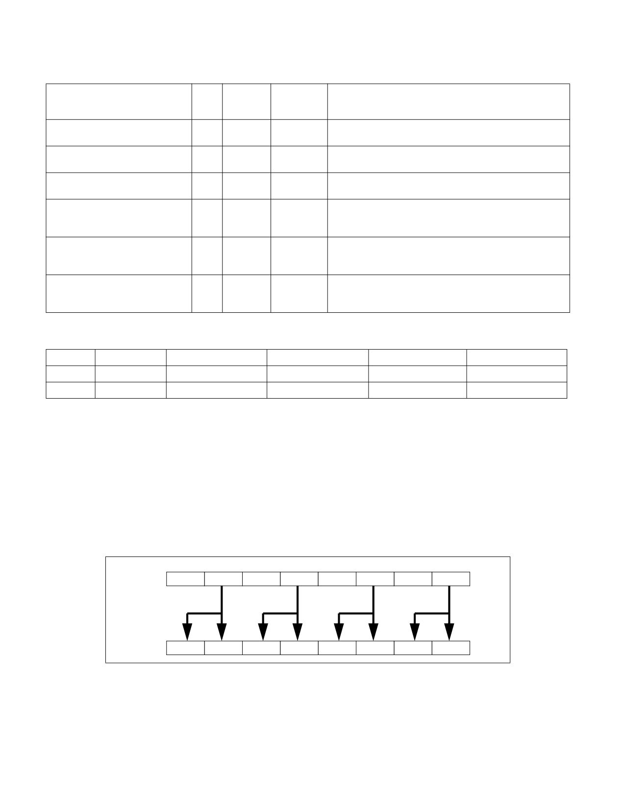
MOVSHDUP (128-bit Legacy SSE Version)
DEST[31:0] := SRC[63:32]
DEST[63:32] := SRC[63:32]
DEST[95:64] := SRC[127:96]
DEST[127:96] := SRC[127:96]
DEST[MAXVL-1:128] (Unmodified)
Intel C/C++ Compiler Intrinsic Equivalent
VMOVSHDUP __m512 _mm512_movehdup_ps( __m512 a);
VMOVSHDUP __m512 _mm512_mask_movehdup_ps(__m512 s, __mmask16 k, __m512 a);
VMOVSHDUP __m512 _mm512_maskz_movehdup_ps( __mmask16 k, __m512 a);
VMOVSHDUP __m256 _mm256_mask_movehdup_ps(__m256 s, __mmask8 k, __m256 a);
VMOVSHDUP __m256 _mm256_maskz_movehdup_ps( __mmask8 k, __m256 a);
VMOVSHDUP __m128 _mm_mask_movehdup_ps(__m128 s, __mmask8 k, __m128 a);
VMOVSHDUP __m128 _mm_maskz_movehdup_ps( __mmask8 k, __m128 a);
VMOVSHDUP __m256 _mm256_movehdup_ps (__m256 a);
VMOVSHDUP __m128 _mm_movehdup_ps (__m128 a);
SIMD Floating-Point Exceptions
None.
Other Exceptions
Non-EVEX-encoded instruction, see Table 2-21, “Type 4 Class Exception Conditions.”
EVEX-encoded instruction, see Exceptions Type E4NF.nb in Table 2-50, “Type E4NF Class Exception Conditions.”
Additionally:
#UD
If EVEX.vvvv != 1111B or VEX.vvvv != 1111B.
MOVSHDUP-Replicate Single Precision Floating-Point Values
Vol. 2B
4-119
INSTRUCTION SET REFERENCE, M-U
MOVSLDUP-Replicate Single Precision Floating-Point Values
Opcode/
Op /
64/32 bit
CPUID
Description
Instruction
En
Mode
Feature
Support
Flag
F3 0F 12 /r
A
V/V
SSE3
Move even index single precision floating-point values from
MOVSLDUP xmm1, xmm2/m128
xmm2/mem and duplicate each element into xmm1.
VEX.128.F3.0F.WIG 12 /r
A
V/V
AVX
Move even index single precision floating-point values from
VMOVSLDUP xmm1, xmm2/m128
xmm2/mem and duplicate each element into xmm1.
VEX.256.F3.0F.WIG 12 /r
A
V/V
AVX
Move even index single precision floating-point values from
VMOVSLDUP ymm1, ymm2/m256
ymm2/mem and duplicate each element into ymm1.
EVEX.128.F3.0F.W0 12 /r
B
V/V
AVX512VL
Move even index single precision floating-point values from
VMOVSLDUP xmm1 {k1}{z},
AVX512F
xmm2/m128 and duplicate each element into xmm1 under
xmm2/m128
writemask.
EVEX.256.F3.0F.W0 12 /r
B
V/V
AVX512VL
Move even index single precision floating-point values from
VMOVSLDUP ymm1 {k1}{z},
AVX512F
ymm2/m256 and duplicate each element into ymm1 under
ymm2/m256
writemask.
EVEX.512.F3.0F.W0 12 /r
B
V/V
AVX512F
Move even index single precision floating-point values from
VMOVSLDUP zmm1 {k1}{z},
zmm2/m512 and duplicate each element into zmm1 under
zmm2/m512
writemask.
Instruction Operand Encoding
Op/En
Tuple Type
Operand 1
Operand 2
Operand 3
Operand 4
A
N/A
ModRM:reg (w)
ModRM:r/m (r)
N/A
N/A
B
Full Mem
ModRM:reg (w)
ModRM:r/m (r)
N/A
N/A
Description
Duplicates even-indexed single precision floating-point values from the source operand (the second operand). See
Figure 4-4. The source operand is an XMM, YMM or ZMM register or 128, 256 or 512-bit memory location and the
destination operand is an XMM, YMM or ZMM register.
128-bit Legacy SSE version: Bits (MAXVL-1:128) of the corresponding destination register remain unchanged.
VEX.128 encoded version: Bits (MAXVL-1:128) of the destination register are zeroed.
VEX.256 encoded version: Bits (MAXVL-1:256) of the destination register are zeroed.
EVEX encoded version: The destination operand is updated at 32-bit granularity according to the writemask.
Note: VEX.vvvv and EVEX.vvvv are reserved and must be 1111b otherwise instructions will #UD.
SRC
X7
X6
X5
X4
X3
X2
X1
X0
DEST
X6
X6
X4
X4
X2
X2
X0
X0
Figure 4-4. MOVSLDUP Operation
4-120
Vol. 2B
MOVSLDUP-Replicate Single Precision Floating-Point Values
INSTRUCTION SET REFERENCE, M-U
Operation
VMOVSLDUP (EVEX Encoded Versions)
(KL, VL) = (4, 128), (8, 256), (16, 512)
TMP_SRC[31:0] := SRC[31:0]
TMP_SRC[63:32] := SRC[31:0]
TMP_SRC[95:64] := SRC[95:64]
TMP_SRC[127:96] := SRC[95:64]
IF VL >= 256
TMP_SRC[159:128] := SRC[159:128]
TMP_SRC[191:160] := SRC[159:128]
TMP_SRC[223:192] := SRC[223:192]
TMP_SRC[255:224] := SRC[223:192]
FI;
IF VL >= 512
TMP_SRC[287:256] := SRC[287:256]
TMP_SRC[319:288] := SRC[287:256]
TMP_SRC[351:320] := SRC[351:320]
TMP_SRC[383:352] := SRC[351:320]
TMP_SRC[415:384] := SRC[415:384]
TMP_SRC[447:416] := SRC[415:384]
TMP_SRC[479:448] := SRC[479:448]
TMP_SRC[511:480] := SRC[479:448]
FI;
FOR j := 0 TO KL-1
i := j * 32
IF k1[j] OR *no writemask*
THEN DEST[i+31:i] := TMP_SRC[i+31:i]
ELSE
IF *merging-masking*
; merging-masking
THEN *DEST[i+31:i] remains unchanged*
ELSE
; zeroing-masking
DEST[i+31:i] := 0
FI
FI;
ENDFOR
DEST[MAXVL-1:VL] := 0
VMOVSLDUP (VEX.256 Encoded Version)
DEST[31:0] := SRC[31:0]
DEST[63:32] := SRC[31:0]
DEST[95:64] := SRC[95:64]
DEST[127:96] := SRC[95:64]
DEST[159:128] := SRC[159:128]
DEST[191:160] := SRC[159:128]
DEST[223:192] := SRC[223:192]
DEST[255:224] := SRC[223:192]
DEST[MAXVL-1:256] := 0
VMOVSLDUP (VEX.128 Encoded Version)
DEST[31:0] := SRC[31:0]
DEST[63:32] := SRC[31:0]
DEST[95:64] := SRC[95:64]
DEST[127:96] := SRC[95:64]
DEST[MAXVL-1:128] := 0
MOVSLDUP-Replicate Single Precision Floating-Point Values
Vol. 2B
4-121
INSTRUCTION SET REFERENCE, M-U
MOVSLDUP (128-bit Legacy SSE Version)
DEST[31:0] := SRC[31:0]
DEST[63:32] := SRC[31:0]
DEST[95:64] := SRC[95:64]
DEST[127:96] := SRC[95:64]
DEST[MAXVL-1:128] (Unmodified)
Intel C/C++ Compiler Intrinsic Equivalent
VMOVSLDUP __m512 _mm512_moveldup_ps( __m512 a);
VMOVSLDUP __m512 _mm512_mask_moveldup_ps(__m512 s, __mmask16 k, __m512 a);
VMOVSLDUP __m512 _mm512_maskz_moveldup_ps( __mmask16 k, __m512 a);
VMOVSLDUP __m256 _mm256_mask_moveldup_ps(__m256 s, __mmask8 k, __m256 a);
VMOVSLDUP __m256 _mm256_maskz_moveldup_ps( __mmask8 k, __m256 a);
VMOVSLDUP __m128 _mm_mask_moveldup_ps(__m128 s, __mmask8 k, __m128 a);
VMOVSLDUP __m128 _mm_maskz_moveldup_ps( __mmask8 k, __m128 a);
VMOVSLDUP __m256 _mm256_moveldup_ps (__m256 a);
VMOVSLDUP __m128 _mm_moveldup_ps (__m128 a);
SIMD Floating-Point Exceptions
None.
Other Exceptions
Non-EVEX-encoded instruction, see Table 2-21, “Type 4 Class Exception Conditions.”
EVEX-encoded instruction, see Exceptions Type E4NF.nb in Table 2-50, “Type E4NF Class Exception Conditions.”
Additionally:
#UD
If EVEX.vvvv != 1111B or VEX.vvvv != 1111B.
4-122
Vol. 2B
MOVSLDUP-Replicate Single Precision Floating-Point Values

INSTRUCTION SET REFERENCE, M-U
MOVSS-Move or Merge Scalar Single Precision Floating-Point Value
Opcode/
Op / En
64/32 bit
CPUID
Description
Instruction
Mode
Feature
Support
Flag
F3 0F 10 /r
A
V/V
SSE
Merge scalar single precision floating-point value from
MOVSS xmm1, xmm2
xmm2 to xmm1 register.
F3 0F 10 /r
A
V/V
SSE
Load scalar single precision floating-point value from
MOVSS xmm1, m32
m32 to xmm1 register.
VEX.LIG.F3.0F.WIG 10 /r
B
V/V
AVX
Merge scalar single precision floating-point value from
VMOVSS xmm1, xmm2, xmm3
xmm2 and xmm3 to xmm1 register
VEX.LIG.F3.0F.WIG 10 /r
D
V/V
AVX
Load scalar single precision floating-point value from
VMOVSS xmm1, m32
m32 to xmm1 register.
F3 0F 11 /r
C
V/V
SSE
Move scalar single precision floating-point value from
MOVSS xmm2/m32, xmm1
xmm1 register to xmm2/m32.
VEX.LIG.F3.0F.WIG 11 /r
E
V/V
AVX
Move scalar single precision floating-point value from
VMOVSS xmm1, xmm2, xmm3
xmm2 and xmm3 to xmm1 register.
VEX.LIG.F3.0F.WIG 11 /r
C
V/V
AVX
Move scalar single precision floating-point value from
VMOVSS m32, xmm1
xmm1 register to m32.
EVEX.LLIG.F3.0F.W0 10 /r
B
V/V
AVX512F
Move scalar single precision floating-point value from
VMOVSS xmm1 {k1}{z}, xmm2, xmm3
xmm2 and xmm3 to xmm1 register under writemask
k1.
EVEX.LLIG.F3.0F.W0 10 /r
F
V/V
AVX512F
Move scalar single precision floating-point values from
VMOVSS xmm1 {k1}{z}, m32
m32 to xmm1 under writemask k1.
EVEX.LLIG.F3.0F.W0 11 /r
E
V/V
AVX512F
Move scalar single precision floating-point value from
VMOVSS xmm1 {k1}{z}, xmm2, xmm3
xmm2 and xmm3 to xmm1 register under writemask
k1.
EVEX.LLIG.F3.0F.W0 11 /r
G
V/V
AVX512F
Move scalar single precision floating-point values from
VMOVSS m32 {k1}, xmm1
xmm1 to m32 under writemask k1.
Instruction Operand Encoding
Op/En
Tuple Type
Operand 1
Operand 2
Operand 3
Operand 4
A
N/A
ModRM:reg (r, w)
ModRM:r/m (r)
N/A
N/A
B
N/A
ModRM:reg (w)
VEX.vvvv (r)
ModRM:r/m (r)
N/A
C
N/A
ModRM:r/m (w)
ModRM:reg (r)
N/A
N/A
D
N/A
ModRM:reg (w)
ModRM:r/m (r)
N/A
N/A
E
N/A
ModRM:r/m (w)
EVEX.vvvv (r)
ModRM:reg (r)
N/A
F
Tuple1 Scalar
ModRM:reg (r, w)
ModRM:r/m (r)
N/A
N/A
G
Tuple1 Scalar
ModRM:r/m (w)
ModRM:reg (r)
N/A
N/A
Description
Moves a scalar single precision floating-point value from the source operand (second operand) to the destination
operand (first operand). The source and destination operands can be XMM registers or 32-bit memory locations.
This instruction can be used to move a single precision floating-point value to and from the low doubleword of an
XMM register and a 32-bit memory location, or to move a single precision floating-point value between the low
doublewords of two XMM registers. The instruction cannot be used to transfer data between memory locations.
Legacy version: When the source and destination operands are XMM registers, bits (MAXVL-1:32) of the corre-
sponding destination register are unmodified. When the source operand is a memory location and destination
MOVSS-Move or Merge Scalar Single Precision Floating-Point Value
Vol. 2B
4-123
INSTRUCTION SET REFERENCE, M-U
operand is an XMM registers, Bits (127:32) of the destination operand is cleared to all 0s, bits MAXVL:128 of the
destination operand remains unchanged.
VEX and EVEX encoded register-register syntax: Moves a scalar single precision floating-point value from the
second source operand (the third operand) to the low doubleword element of the destination operand (the first
operand). Bits 127:32 of the destination operand are copied from the first source operand (the second operand).
Bits (MAXVL-1:128) of the corresponding destination register are zeroed.
VEX and EVEX encoded memory load syntax: When the source operand is a memory location and destination
operand is an XMM registers, bits MAXVL:32 of the destination operand is cleared to all 0s.
EVEX encoded versions: The low doubleword of the destination is updated according to the writemask.
Note: For memory store form instruction “VMOVSS m32, xmm1”, VEX.vvvv is reserved and must be 1111b other-
wise instruction will #UD. For memory store form instruction “VMOVSS mv {k1}, xmm1”, EVEX.vvvv is reserved
and must be 1111b otherwise instruction will #UD.
Software should ensure VMOVSS is encoded with VEX.L=0. Encoding VMOVSS with VEX.L=1 may encounter unpre-
dictable behavior across different processor generations.
Operation
VMOVSS (EVEX.LLIG.F3.0F.W0 11 /r When the Source Operand is Memory and the Destination is an XMM Register)
IF k1[0] or *no writemask*
THEN
DEST[31:0] := SRC[31:0]
ELSE
IF *merging-masking*
; merging-masking
THEN *DEST[31:0] remains unchanged*
ELSE
; zeroing-masking
THEN DEST[31:0] := 0
FI;
FI;
DEST[MAXVL-1:32] := 0
VMOVSS (EVEX.LLIG.F3.0F.W0 10 /r When the Source Operand is an XMM Register and the Destination is Memory)
IF k1[0] or *no writemask*
THEN
DEST[31:0] := SRC[31:0]
ELSE
*DEST[31:0] remains unchanged*
; merging-masking
FI;
VMOVSS (EVEX.LLIG.F3.0F.W0 10/11 /r Where the Source and Destination are XMM Registers)
IF k1[0] or *no writemask*
THEN
DEST[31:0] := SRC2[31:0]
ELSE
IF *merging-masking*
; merging-masking
THEN *DEST[31:0] remains unchanged*
ELSE
; zeroing-masking
THEN DEST[31:0] := 0
FI;
FI;
DEST[127:32] := SRC1[127:32]
DEST[MAXVL-1:128] := 0
MOVSS (Legacy SSE Version When the Source and Destination Operands are Both XMM Registers)
DEST[31:0] := SRC[31:0]
DEST[MAXVL-1:32] (Unmodified)
4-124
Vol. 2B
MOVSS-Move or Merge Scalar Single Precision Floating-Point Value
INSTRUCTION SET REFERENCE, M-U
VMOVSS (VEX.128.F3.0F 11 /r Where the Destination is an XMM Register)
DEST[31:0] := SRC2[31:0]
DEST[127:32] := SRC1[127:32]
DEST[MAXVL-1:128] := 0
VMOVSS (VEX.128.F3.0F 10 /r Where the Source and Destination are XMM Registers)
DEST[31:0] := SRC2[31:0]
DEST[127:32] := SRC1[127:32]
DEST[MAXVL-1:128] := 0
VMOVSS (VEX.128.F3.0F 10 /r When the Source Operand is Memory and the Destination is an XMM Register)
DEST[31:0] := SRC[31:0]
DEST[MAXVL-1:32] := 0
MOVSS/VMOVSS (When the Source Operand is an XMM Register and the Destination is Memory)
DEST[31:0] := SRC[31:0]
MOVSS (Legacy SSE Version when the Source Operand is Memory and the Destination is an XMM Register)
DEST[31:0] := SRC[31:0]
DEST[127:32] := 0
DEST[MAXVL-1:128] (Unmodified)
Intel C/C++ Compiler Intrinsic Equivalent
VMOVSS __m128 _mm_mask_load_ss(__m128 s, __mmask8 k, float * p);
VMOVSS __m128 _mm_maskz_load_ss( __mmask8 k, float * p);
VMOVSS __m128 _mm_mask_move_ss(__m128 sh, __mmask8 k, __m128 sl, __m128 a);
VMOVSS __m128 _mm_maskz_move_ss( __mmask8 k, __m128 s, __m128 a);
VMOVSS void _mm_mask_store_ss(float * p, __mmask8 k, __m128 a);
MOVSS __m128 _mm_load_ss(float * p)
MOVSS void_mm_store_ss(float * p, __m128 a)
MOVSS __m128 _mm_move_ss(__m128 a, __m128 b)
SIMD Floating-Point Exceptions
None.
Other Exceptions
Non-EVEX-encoded instruction, see Table 2-22, “Type 5 Class Exception Conditions,” additionally:
#UD
If VEX.vvvv != 1111B.
EVEX-encoded instruction, see Table 2-58, “Type E10 Class Exception Conditions.”
MOVSS-Move or Merge Scalar Single Precision Floating-Point Value
Vol. 2B
4-125

INSTRUCTION SET REFERENCE, M-U
MOVSX/MOVSXD-Move With Sign-Extension
Opcode
Instruction
Op/
64-Bit
Compat/
Description
En
Mode
Leg Mode
0F BE /r
MOVSX r16, r/m8
RM
Valid
Valid
Move byte to word with sign-extension.
0F BE /r
MOVSX r32, r/m8
RM
Valid
Valid
Move byte to doubleword with sign-
extension.
REX.W + 0F BE /r
MOVSX r64, r/m8
RM
Valid
N.E.
Move byte to quadword with sign-extension.
0F BF /r
MOVSX r32, r/m16
RM
Valid
Valid
Move word to doubleword, with sign-
extension.
REX.W + 0F BF /r
MOVSX r64, r/m16
RM
Valid
N.E.
Move word to quadword with sign-extension.
63 /r1
MOVSXD r16, r/m16
RM
Valid
N.E.
Move word to word with sign-extension.
63 /r1
MOVSXD r32, r/m32
RM
Valid
N.E.
Move doubleword to doubleword with sign-
extension.
REX.W + 63 /r
MOVSXD r64, r/m32
RM
Valid
N.E.
Move doubleword to quadword with sign-
extension.
NOTES:
1. The use of MOVSXD without REX.W in 64-bit mode is discouraged. Regular MOV should be used instead of using MOVSXD without
REX.W.
Instruction Operand Encoding
Op/En
Operand 1
Operand 2
Operand 3
Operand 4
RM
ModRM:reg (w)
ModRM:r/m (r)
N/A
N/A
Description
Copies the contents of the source operand (register or memory location) to the destination operand (register) and
sign extends the value to 16 or 32 bits (see Figure 7-6 in the Intel® 64 and IA-32 Architectures Software Devel-
oper’s Manual, Volume 1). The size of the converted value depends on the operand-size attribute.
In 64-bit mode, the instruction’s default operation size is 32 bits. Use of the REX.R prefix permits access to addi-
tional registers (R8-R15). Use of the REX.W prefix promotes operation to 64 bits. See the summary chart at the
beginning of this section for encoding data and limits.
Operation
DEST := SignExtend(SRC);
Flags Affected
None.
Protected Mode Exceptions
#GP(0)
If a memory operand effective address is outside the CS, DS, ES, FS, or GS segment limit.
If the DS, ES, FS, or GS register contains a NULL segment selector.
#SS(0)
If a memory operand effective address is outside the SS segment limit.
#PF(fault-code)
If a page fault occurs.
#AC(0)
If alignment checking is enabled and an unaligned memory reference is made while the
current privilege level is 3.
#UD
If the LOCK prefix is used.
4-126
Vol. 2B
MOVSX/MOVSXD-Move With Sign-Extension
INSTRUCTION SET REFERENCE, M-U
Real-Address Mode Exceptions
#GP
If a memory operand effective address is outside the CS, DS, ES, FS, or GS segment limit.
#SS
If a memory operand effective address is outside the SS segment limit.
#UD
If the LOCK prefix is used.
Virtual-8086 Mode Exceptions
#GP(0)
If a memory operand effective address is outside the CS, DS, ES, FS, or GS segment limit.
#SS(0)
If a memory operand effective address is outside the SS segment limit.
#PF(fault-code)
If a page fault occurs.
#UD
If the LOCK prefix is used.
Compatibility Mode Exceptions
Same exceptions as in protected mode.
64-Bit Mode Exceptions
#SS(0)
If a memory address referencing the SS segment is in a non-canonical form.
#GP(0)
If the memory address is in a non-canonical form.
#PF(fault-code)
If a page fault occurs.
#AC(0)
If alignment checking is enabled and an unaligned memory reference is made while the
current privilege level is 3.
#UD
If the LOCK prefix is used.
MOVSX/MOVSXD-Move With Sign-Extension
Vol. 2B
4-127

INSTRUCTION SET REFERENCE, M-U
MOVUPD-Move Unaligned Packed Double Precision Floating-Point Values
Opcode/
Op / En
64/32 bit
CPUID
Description
Instruction
Mode
Feature
Support
Flag
66 0F 10 /r
A
V/V
SSE2
Move unaligned packed double precision floating-
MOVUPD xmm1, xmm2/m128
point from xmm2/mem to xmm1.
66 0F 11 /r
B
V/V
SSE2
Move unaligned packed double precision floating-
MOVUPD xmm2/m128, xmm1
point from xmm1 to xmm2/mem.
VEX.128.66.0F.WIG 10 /r
A
V/V
AVX
Move unaligned packed double precision floating-
VMOVUPD xmm1, xmm2/m128
point from xmm2/mem to xmm1.
VEX.128.66.0F.WIG 11 /r
B
V/V
AVX
Move unaligned packed double precision floating-
VMOVUPD xmm2/m128, xmm1
point from xmm1 to xmm2/mem.
VEX.256.66.0F.WIG 10 /r
A
V/V
AVX
Move unaligned packed double precision floating-
VMOVUPD ymm1, ymm2/m256
point from ymm2/mem to ymm1.
VEX.256.66.0F.WIG 11 /r
B
V/V
AVX
Move unaligned packed double precision floating-
VMOVUPD ymm2/m256, ymm1
point from ymm1 to ymm2/mem.
EVEX.128.66.0F.W1 10 /r
C
V/V
AVX512VL
Move unaligned packed double precision floating-
VMOVUPD xmm1 {k1}{z}, xmm2/m128
AVX512F
point from xmm2/m128 to xmm1 using writemask
k1.
EVEX.128.66.0F.W1 11 /r
D
V/V
AVX512VL
Move unaligned packed double precision floating-
VMOVUPD xmm2/m128 {k1}{z}, xmm1
AVX512F
point from xmm1 to xmm2/m128 using writemask
k1.
EVEX.256.66.0F.W1 10 /r
C
V/V
AVX512VL
Move unaligned packed double precision floating-
VMOVUPD ymm1 {k1}{z}, ymm2/m256
AVX512F
point from ymm2/m256 to ymm1 using writemask
k1.
EVEX.256.66.0F.W1 11 /r
D
V/V
AVX512VL
Move unaligned packed double precision floating-
VMOVUPD ymm2/m256 {k1}{z}, ymm1
AVX512F
point from ymm1 to ymm2/m256 using writemask
k1.
EVEX.512.66.0F.W1 10 /r
C
V/V
AVX512F
Move unaligned packed double precision floating-
VMOVUPD zmm1 {k1}{z}, zmm2/m512
point values from zmm2/m512 to zmm1 using
writemask k1.
EVEX.512.66.0F.W1 11 /r
D
V/V
AVX512F
Move unaligned packed double precision floating-
VMOVUPD zmm2/m512 {k1}{z}, zmm1
point values from zmm1 to zmm2/m512 using
writemask k1.
Instruction Operand Encoding
Op/En
Tuple Type
Operand 1
Operand 2
Operand 3
Operand 4
A
N/A
ModRM:reg (w)
ModRM:r/m (r)
N/A
N/A
B
N/A
ModRM:r/m (w)
ModRM:reg (r)
N/A
N/A
C
Full Mem
ModRM:reg (w)
ModRM:r/m (r)
N/A
N/A
D
Full Mem
ModRM:r/m (w)
ModRM:reg (r)
N/A
N/A
Description
Note: VEX.vvvv and EVEX.vvvv is reserved and must be 1111b otherwise instructions will #UD.
EVEX.512 encoded version:
Moves 512 bits of packed double precision floating-point values from the source operand (second operand) to the
destination operand (first operand). This instruction can be used to load a ZMM register from a float64 memory
location, to store the contents of a ZMM register into a memory. The destination operand is updated according to
the writemask.
4-128
Vol. 2B
MOVUPD-Move Unaligned Packed Double Precision Floating-Point Values
INSTRUCTION SET REFERENCE, M-U
VEX.256 encoded version:
Moves 256 bits of packed double precision floating-point values from the source operand (second operand) to the
destination operand (first operand). This instruction can be used to load a YMM register from a 256-bit memory
location, to store the contents of a YMM register into a 256-bit memory location, or to move data between two YMM
registers. Bits (MAXVL-1:256) of the destination register are zeroed.
128-bit versions:
Moves 128 bits of packed double precision floating-point values from the source operand (second operand) to the
destination operand (first operand). This instruction can be used to load an XMM register from a 128-bit memory
location, to store the contents of an XMM register into a 128-bit memory location, or to move data between two
XMM registers.
128-bit Legacy SSE version: Bits (MAXVL-1:128) of the corresponding destination register remain unchanged.
When the source or destination operand is a memory operand, the operand may be unaligned on a 16-byte
boundary without causing a general-protection exception (#GP) to be generated
VEX.128 and EVEX.128 encoded versions: Bits (MAXVL-1:128) of the destination register are zeroed.
Operation
VMOVUPD (EVEX Encoded Versions, Register-Copy Form)
(KL, VL) = (2, 128), (4, 256), (8, 512)
FOR j := 0 TO KL-1
i := j * 64
IF k1[j] OR *no writemask*
THEN DEST[i+63:i] := SRC[i+63:i]
ELSE
IF *merging-masking*
; merging-masking
THEN *DEST[i+63:i] remains unchanged*
ELSE DEST[i+63:i] := 0
; zeroing-masking
FI
FI;
ENDFOR
DEST[MAXVL-1:VL] := 0
VMOVUPD (EVEX Encoded Versions, Store-Form)
(KL, VL) = (2, 128), (4, 256), (8, 512)
FOR j := 0 TO KL-1
i := j * 64
IF k1[j] OR *no writemask*
THEN DEST[i+63:i] := SRC[i+63:i]
ELSE *DEST[i+63:i] remains unchanged*
; merging-masking
FI;
ENDFOR;
MOVUPD-Move Unaligned Packed Double Precision Floating-Point Values
Vol. 2B
4-129
INSTRUCTION SET REFERENCE, M-U
VMOVUPD (EVEX Encoded Versions, Load-Form)
(KL, VL) = (2, 128), (4, 256), (8, 512)
FOR j := 0 TO KL-1
i := j * 64
IF k1[j] OR *no writemask*
THEN DEST[i+63:i] := SRC[i+63:i]
ELSE
IF *merging-masking*
; merging-masking
THEN *DEST[i+63:i] remains unchanged*
ELSE DEST[i+63:i] := 0
; zeroing-masking
FI
FI;
ENDFOR
DEST[MAXVL-1:VL] := 0
VMOVUPD (VEX.256 Encoded Version, Load - and Register Copy)
DEST[255:0] := SRC[255:0]
DEST[MAXVL-1:256] := 0
VMOVUPD (VEX.256 Encoded Version, Store-Form)
DEST[255:0] := SRC[255:0]
VMOVUPD (VEX.128 Encoded Version)
DEST[127:0] := SRC[127:0]
DEST[MAXVL-1:128] := 0
MOVUPD (128-bit Load- and Register-Copy- Form Legacy SSE Version)
DEST[127:0] := SRC[127:0]
DEST[MAXVL-1:128] (Unmodified)
(V)MOVUPD (128-bit Store-Form Version)
DEST[127:0] := SRC[127:0]
Intel C/C++ Compiler Intrinsic Equivalent
VMOVUPD __m512d _mm512_loadu_pd( void * s);
VMOVUPD __m512d _mm512_mask_loadu_pd(__m512d a, __mmask8 k, void * s);
VMOVUPD __m512d _mm512_maskz_loadu_pd( __mmask8 k, void * s);
VMOVUPD void _mm512_storeu_pd( void * d, __m512d a);
VMOVUPD void _mm512_mask_storeu_pd( void * d, __mmask8 k, __m512d a);
VMOVUPD __m256d _mm256_mask_loadu_pd(__m256d s, __mmask8 k, void * m);
VMOVUPD __m256d _mm256_maskz_loadu_pd( __mmask8 k, void * m);
VMOVUPD void _mm256_mask_storeu_pd( void * d, __mmask8 k, __m256d a);
VMOVUPD __m128d _mm_mask_loadu_pd(__m128d s, __mmask8 k, void * m);
VMOVUPD __m128d _mm_maskz_loadu_pd( __mmask8 k, void * m);
VMOVUPD void _mm_mask_storeu_pd( void * d, __mmask8 k, __m128d a);
MOVUPD __m256d _mm256_loadu_pd (double * p);
MOVUPD void _mm256_storeu_pd( double *p, __m256d a);
MOVUPD __m128d _mm_loadu_pd (double * p);
MOVUPD void _mm_storeu_pd( double *p, __m128d a);
SIMD Floating-Point Exceptions
None.
4-130
Vol. 2B
MOVUPD-Move Unaligned Packed Double Precision Floating-Point Values
INSTRUCTION SET REFERENCE, M-U
Other Exceptions
Non-EVEX-encoded instruction, see Table 2-21, “Type 4 Class Exception Conditions.”
Note treatment of #AC varies; additionally:
#UD
If VEX.vvvv != 1111B.
EVEX-encoded instruction, see Exceptions Type E4.nb in Table 2-49, “Type E4 Class Exception Conditions.”
MOVUPD-Move Unaligned Packed Double Precision Floating-Point Values
Vol. 2B
4-131

INSTRUCTION SET REFERENCE, M-U
MOVUPS-Move Unaligned Packed Single Precision Floating-Point Values
Opcode/
Op / En
64/32 bit
CPUID
Description
Instruction
Mode
Feature
Support
Flag
NP 0F 10 /r
A
V/V
SSE
Move unaligned packed single precision floating-
MOVUPS xmm1, xmm2/m128
point from xmm2/mem to xmm1.
NP 0F 11 /r
B
V/V
SSE
Move unaligned packed single precision floating-
MOVUPS xmm2/m128, xmm1
point from xmm1 to xmm2/mem.
VEX.128.0F.WIG 10 /r
A
V/V
AVX
Move unaligned packed single precision floating-
VMOVUPS xmm1, xmm2/m128
point from xmm2/mem to xmm1.
VEX.128.0F.WIG 11 /r
B
V/V
AVX
Move unaligned packed single precision floating-
VMOVUPS xmm2/m128, xmm1
point from xmm1 to xmm2/mem.
VEX.256.0F.WIG 10 /r
A
V/V
AVX
Move unaligned packed single precision floating-
VMOVUPS ymm1, ymm2/m256
point from ymm2/mem to ymm1.
VEX.256.0F.WIG 11 /r
B
V/V
AVX
Move unaligned packed single precision floating-
VMOVUPS ymm2/m256, ymm1
point from ymm1 to ymm2/mem.
EVEX.128.0F.W0 10 /r
C
V/V
AVX512VL
Move unaligned packed single precision floating-
VMOVUPS xmm1 {k1}{z}, xmm2/m128
AVX512F
point values from xmm2/m128 to xmm1 using
writemask k1.
EVEX.256.0F.W0 10 /r
C
V/V
AVX512VL
Move unaligned packed single precision floating-
VMOVUPS ymm1 {k1}{z}, ymm2/m256
AVX512F
point values from ymm2/m256 to ymm1 using
writemask k1.
EVEX.512.0F.W0 10 /r
C
V/V
AVX512F
Move unaligned packed single precision floating-
VMOVUPS zmm1 {k1}{z}, zmm2/m512
point values from zmm2/m512 to zmm1 using
writemask k1.
EVEX.128.0F.W0 11 /r
D
V/V
AVX512VL
Move unaligned packed single precision floating-
VMOVUPS xmm2/m128 {k1}{z}, xmm1
AVX512F
point values from xmm1 to xmm2/m128 using
writemask k1.
EVEX.256.0F.W0 11 /r
D
V/V
AVX512VL
Move unaligned packed single precision floating-
VMOVUPS ymm2/m256 {k1}{z}, ymm1
AVX512F
point values from ymm1 to ymm2/m256 using
writemask k1.
EVEX.512.0F.W0 11 /r
D
V/V
AVX512F
Move unaligned packed single precision floating-
VMOVUPS zmm2/m512 {k1}{z}, zmm1
point values from zmm1 to zmm2/m512 using
writemask k1.
Instruction Operand Encoding
Op/En
Tuple Type
Operand 1
Operand 2
Operand 3
Operand 4
A
N/A
ModRM:reg (w)
ModRM:r/m (r)
N/A
N/A
B
N/A
ModRM:r/m (w)
ModRM:reg (r)
N/A
N/A
C
Full Mem
ModRM:reg (w)
ModRM:r/m (r)
N/A
N/A
D
Full Mem
ModRM:r/m (w)
ModRM:reg (r)
N/A
N/A
Description
Note: VEX.vvvv and EVEX.vvvv is reserved and must be 1111b otherwise instructions will #UD.
EVEX.512 encoded version:
Moves 512 bits of packed single precision floating-point values from the source operand (second operand) to the
destination operand (first operand). This instruction can be used to load a ZMM register from a 512-bit float32
memory location, to store the contents of a ZMM register into memory. The destination operand is updated
according to the writemask.
4-132
Vol. 2B
MOVUPS-Move Unaligned Packed Single Precision Floating-Point Values
INSTRUCTION SET REFERENCE, M-U
VEX.256 and EVEX.256 encoded versions:
Moves 256 bits of packed single precision floating-point values from the source operand (second operand) to the
destination operand (first operand). This instruction can be used to load a YMM register from a 256-bit memory
location, to store the contents of a YMM register into a 256-bit memory location, or to move data between two YMM
registers. Bits (MAXVL-1:256) of the destination register are zeroed.
128-bit versions:
Moves 128 bits of packed single precision floating-point values from the source operand (second operand) to the
destination operand (first operand). This instruction can be used to load an XMM register from a 128-bit memory
location, to store the contents of an XMM register into a 128-bit memory location, or to move data between two
XMM registers.
128-bit Legacy SSE version: Bits (MAXVL-1:128) of the corresponding destination register remain unchanged.
When the source or destination operand is a memory operand, the operand may be unaligned without causing a
general-protection exception (#GP) to be generated.
VEX.128 and EVEX.128 encoded versions: Bits (MAXVL-1:128) of the destination register are zeroed.
Operation
VMOVUPS (EVEX Encoded Versions, Register-Copy Form)
(KL, VL) = (4, 128), (8, 256), (16, 512)
FOR j := 0 TO KL-1
i := j * 32
IF k1[j] OR *no writemask*
THEN DEST[i+31:i] := SRC[i+31:i]
ELSE
IF *merging-masking*
; merging-masking
THEN *DEST[i+31:i] remains unchanged*
ELSE DEST[i+31:i] := 0
; zeroing-masking
FI
FI;
ENDFOR
DEST[MAXVL-1:VL] := 0
VMOVUPS (EVEX Encoded Versions, Store-Form)
(KL, VL) = (4, 128), (8, 256), (16, 512)
FOR j := 0 TO KL-1
i := j * 32
IF k1[j] OR *no writemask*
THEN DEST[i+31:i] := SRC[i+31:i]
ELSE *DEST[i+31:i] remains unchanged*
; merging-masking
FI;
ENDFOR;
MOVUPS-Move Unaligned Packed Single Precision Floating-Point Values
Vol. 2B
4-133
INSTRUCTION SET REFERENCE, M-U
VMOVUPS (EVEX Encoded Versions, Load-Form)
(KL, VL) = (4, 128), (8, 256), (16, 512)
FOR j := 0 TO KL-1
i := j * 32
IF k1[j] OR *no writemask*
THEN DEST[i+31:i] := SRC[i+31:i]
ELSE
IF *merging-masking*
; merging-masking
THEN *DEST[i+31:i] remains unchanged*
ELSE DEST[i+31:i] := 0
; zeroing-masking
FI
FI;
ENDFOR
DEST[MAXVL-1:VL] := 0
VMOVUPS (VEX.256 Encoded Version, Load - and Register Copy)
DEST[255:0] := SRC[255:0]
DEST[MAXVL-1:256] := 0
VMOVUPS (VEX.256 Encoded Version, Store-Form)
DEST[255:0] := SRC[255:0]
VMOVUPS (VEX.128 Encoded Version)
DEST[127:0] := SRC[127:0]
DEST[MAXVL-1:128] := 0
MOVUPS (128-bit Load- and Register-Copy- Form Legacy SSE Version)
DEST[127:0] := SRC[127:0]
DEST[MAXVL-1:128] (Unmodified)
(V)MOVUPS (128-bit Store-Form Version)
DEST[127:0] := SRC[127:0]
Intel C/C++ Compiler Intrinsic Equivalent
VMOVUPS __m512 _mm512_loadu_ps( void * s);
VMOVUPS __m512 _mm512_mask_loadu_ps(__m512 a, __mmask16 k, void * s);
VMOVUPS __m512 _mm512_maskz_loadu_ps( __mmask16 k, void * s);
VMOVUPS void _mm512_storeu_ps( void * d, __m512 a);
VMOVUPS void _mm512_mask_storeu_ps( void * d, __mmask8 k, __m512 a);
VMOVUPS __m256 _mm256_mask_loadu_ps(__m256 a, __mmask8 k, void * s);
VMOVUPS __m256 _mm256_maskz_loadu_ps( __mmask8 k, void * s);
VMOVUPS void _mm256_mask_storeu_ps( void * d, __mmask8 k, __m256 a);
VMOVUPS __m128 _mm_mask_loadu_ps(__m128 a, __mmask8 k, void * s);
VMOVUPS __m128 _mm_maskz_loadu_ps( __mmask8 k, void * s);
VMOVUPS void _mm_mask_storeu_ps( void * d, __mmask8 k, __m128 a);
MOVUPS __m256 _mm256_loadu_ps ( float * p);
MOVUPS void _mm256 _storeu_ps( float *p, __m256 a);
MOVUPS __m128 _mm_loadu_ps ( float * p);
MOVUPS void _mm_storeu_ps( float *p, __m128 a);
SIMD Floating-Point Exceptions
None.
4-134
Vol. 2B
MOVUPS-Move Unaligned Packed Single Precision Floating-Point Values
INSTRUCTION SET REFERENCE, M-U
Other Exceptions
Non-EVEX-encoded instruction, see Table 2-21, “Type 4 Class Exception Conditions.”
Note treatment of #AC varies.
EVEX-encoded instruction, see Exceptions Type E4.nb in Table 2-49, “Type E4 Class Exception Conditions.”
Additionally:
#UD
If EVEX.vvvv != 1111B or VEX.vvvv != 1111B.
MOVUPS-Move Unaligned Packed Single Precision Floating-Point Values
Vol. 2B
4-135
INSTRUCTION SET REFERENCE, M-U
MOVZX-Move With Zero-Extend
Opcode
Instruction
Op/
64-Bit
Compat/
Description
En
Mode
Leg Mode
0F B6 /r
MOVZX r16, r/m8
RM
Valid
Valid
Move byte to word with zero-extension.
0F B6 /r
MOVZX r32, r/m8
RM
Valid
Valid
Move byte to doubleword, zero-extension.
REX.W + 0F B6 /r
MOVZX r64, r/m81
RM
Valid
N.E.
Move byte to quadword, zero-extension.
0F B7 /r
MOVZX r32, r/m16
RM
Valid
Valid
Move word to doubleword, zero-extension.
REX.W + 0F B7 /r
MOVZX r64, r/m16
RM
Valid
N.E.
Move word to quadword, zero-extension.
NOTES:
1. In 64-bit mode, r/m8 can not be encoded to access the following byte registers if the REX prefix is used: AH, BH, CH, DH.
Instruction Operand Encoding
Op/En
Operand 1
Operand 2
Operand 3
Operand 4
RM
ModRM:reg (w)
ModRM:r/m (r)
N/A
N/A
Description
Copies the contents of the source operand (register or memory location) to the destination operand (register) and
zero extends the value. The size of the converted value depends on the operand-size attribute.
In 64-bit mode, the instruction’s default operation size is 32 bits. Use of the REX.R prefix permits access to addi-
tional registers (R8-R15). Use of the REX.W prefix promotes operation to 64 bit operands. See the summary chart
at the beginning of this section for encoding data and limits.
Operation
DEST := ZeroExtend(SRC);
Flags Affected
None.
Protected Mode Exceptions
#GP(0)
If a memory operand effective address is outside the CS, DS, ES, FS, or GS segment limit.
If the DS, ES, FS, or GS register contains a NULL segment selector.
#SS(0)
If a memory operand effective address is outside the SS segment limit.
#PF(fault-code)
If a page fault occurs.
#AC(0)
If alignment checking is enabled and an unaligned memory reference is made while the
current privilege level is 3.
#UD
If the LOCK prefix is used.
Real-Address Mode Exceptions
#GP
If a memory operand effective address is outside the CS, DS, ES, FS, or GS segment limit.
#SS
If a memory operand effective address is outside the SS segment limit.
#UD
If the LOCK prefix is used.
4-136
Vol. 2B
MOVZX-Move With Zero-Extend
INSTRUCTION SET REFERENCE, M-U
Virtual-8086 Mode Exceptions
#GP(0)
If a memory operand effective address is outside the CS, DS, ES, FS, or GS segment limit.
#SS(0)
If a memory operand effective address is outside the SS segment limit.
#PF(fault-code)
If a page fault occurs.
#AC(0)
If alignment checking is enabled and an unaligned memory reference is made.
#UD
If the LOCK prefix is used.
Compatibility Mode Exceptions
Same exceptions as in protected mode.
64-Bit Mode Exceptions
#SS(0)
If a memory address referencing the SS segment is in a non-canonical form.
#GP(0)
If the memory address is in a non-canonical form.
#PF(fault-code)
If a page fault occurs.
#AC(0)
If alignment checking is enabled and an unaligned memory reference is made while the
current privilege level is 3.
#UD
If the LOCK prefix is used.
MOVZX-Move With Zero-Extend
Vol. 2B
4-137
INSTRUCTION SET REFERENCE, M-U
MPSADBW-Compute Multiple Packed Sums of Absolute Difference
Opcode/
Op/
64/32-bit
CPUID
Description
Instruction
En
Mode
Feature
Flag
66 0F 3A 42 /r ib
RMI
V/V
SSE4_1
Sums absolute 8-bit integer difference of
adjacent groups of 4 byte integers in xmm1
MPSADBW xmm1, xmm2/m128, imm8
and xmm2/m128 and writes the results in
xmm1. Starting offsets within xmm1 and
xmm2/m128 are determined by imm8.
VEX.128.66.0F3A.WIG 42 /r ib
RVMI
V/V
AVX
Sums absolute 8-bit integer difference of
adjacent groups of 4 byte integers in xmm2
VMPSADBW xmm1, xmm2, xmm3/m128, imm8
and xmm3/m128 and writes the results in
xmm1. Starting offsets within xmm2 and
xmm3/m128 are determined by imm8.
VEX.256.66.0F3A.WIG 42 /r ib
RVMI
V/V
AVX2
Sums absolute 8-bit integer difference of
adjacent groups of 4 byte integers in xmm2
VMPSADBW ymm1, ymm2, ymm3/m256, imm8
and ymm3/m128 and writes the results in
ymm1. Starting offsets within ymm2 and
xmm3/m128 are determined by imm8.
Instruction Operand Encoding
Op/En
Operand 1
Operand 2
Operand 3
Operand 4
RMI
ModRM:reg (r, w)
ModRM:r/m (r)
imm8
N/A
RVMI
ModRM:reg (w)
VEX.vvvv (r)
ModRM:r/m (r)
imm8
Description
(V)MPSADBW calculates packed word results of sum-absolute-difference (SAD) of unsigned bytes from two blocks
of 32-bit dword elements, using two select fields in the immediate byte to select the offsets of the two blocks within
the first source operand and the second operand. Packed SAD word results are calculated within each 128-bit lane.
Each SAD word result is calculated between a stationary block_2 (whose offset within the second source operand
is selected by a two bit select control, multiplied by 32 bits) and a sliding block_1 at consecutive byte-granular posi-
tion within the first source operand. The offset of the first 32-bit block of block_1 is selectable using a one bit select
control, multiplied by 32 bits.
128-bit Legacy SSE version: Imm8[1:0]*32 specifies the bit offset of block_2 within the second source operand.
Imm[2]*32 specifies the initial bit offset of the block_1 within the first source operand. The first source operand
and destination operand are the same. The first source and destination operands are XMM registers. The second
source operand is either an XMM register or a 128-bit memory location. Bits (MAXVL-1:128) of the corresponding
YMM destination register remain unchanged. Bits 7:3 of the immediate byte are ignored.
VEX.128 encoded version: Imm8[1:0]*32 specifies the bit offset of block_2 within the second source operand.
Imm[2]*32 specifies the initial bit offset of the block_1 within the first source operand. The first source and desti-
nation operands are XMM registers. The second source operand is either an XMM register or a 128-bit memory
location. Bits (127:128) of the corresponding YMM register are zeroed. Bits 7:3 of the immediate byte are ignored.
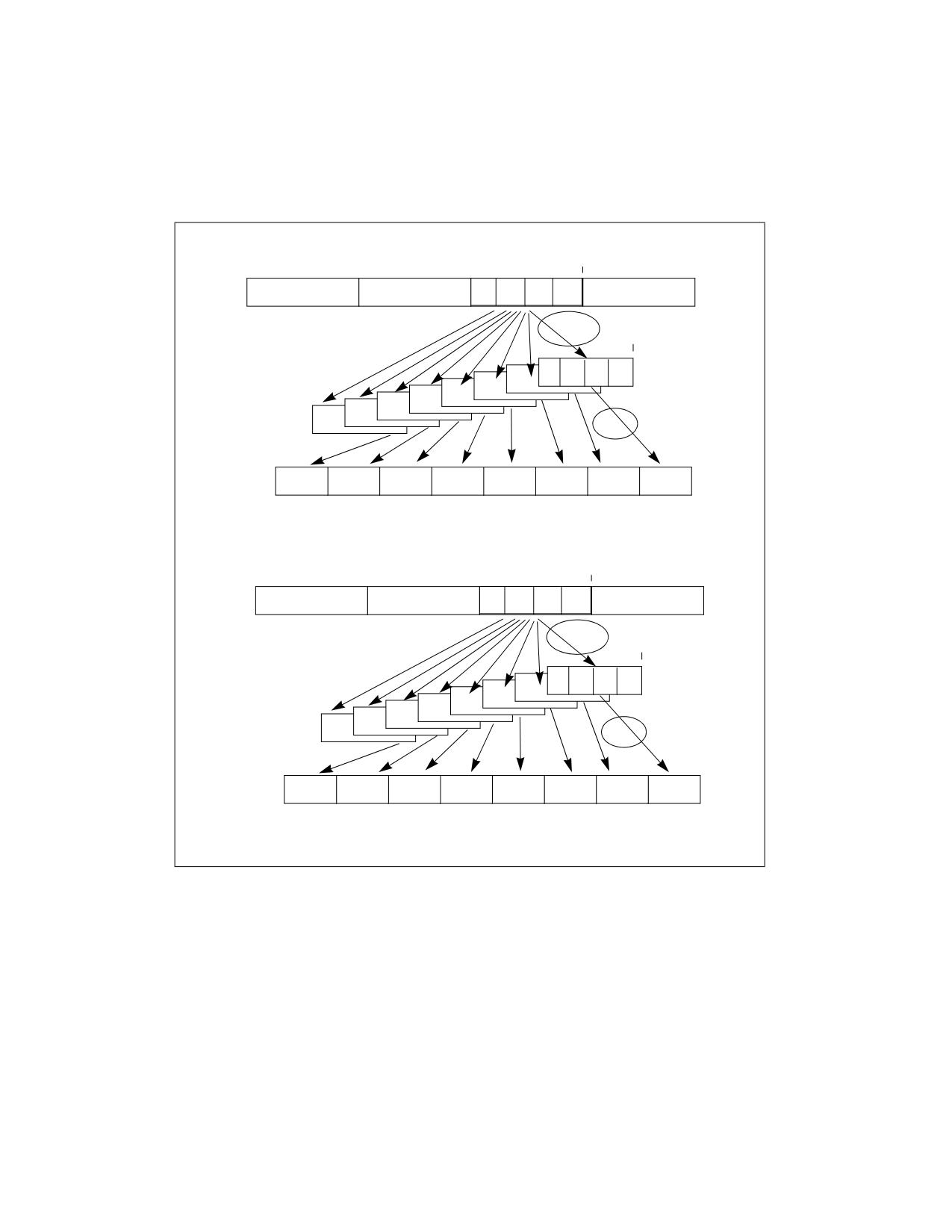
VEX.256 encoded version: The sum-absolute-difference (SAD) operation is repeated 8 times for MPSADW between
the same block_2 (fixed offset within the second source operand) and a variable block_1 (offset is shifted by 8 bits
for each SAD operation) in the first source operand. Each 16-bit result of eight SAD operations between block_2
and block_1 is written to the respective word in the lower 128 bits of the destination operand.
Additionally, VMPSADBW performs another eight SAD operations on block_4 of the second source operand and
block_3 of the first source operand. (Imm8[4:3]*32 + 128) specifies the bit offset of block_4 within the second
source operand. (Imm[5]*32+128) specifies the initial bit offset of the block_3 within the first source operand.
Each 16-bit result of eight SAD operations between block_4 and block_3 is written to the respective word in the
upper 128 bits of the destination operand.
4-138
Vol. 2B
MPSADBW-Compute Multiple Packed Sums of Absolute Difference
INSTRUCTION SET REFERENCE, M-U
The first source operand is a YMM register. The second source register can be a YMM register or a 256-bit memory
location. The destination operand is a YMM register. Bits 7:6 of the immediate byte are ignored.
Note: If VMPSADBW is encoded with VEX.L= 1, an attempt to execute the instruction encoded with VEX.L= 1 will
cause an #UD exception.
Imm[4:3]*32+128
255
224
192
128
Src2
Abs. Diff.
Imm[5]*32+128
Src1
Sum
255
144
128
Destination
Imm[1:0]*32
127
96
64
0
Src2
Abs. Diff.
Imm[2]*32
Src1
Sum
127
16
0
Destination
Figure 4-5. 256-bit VMPSADBW Operation
Operation
VMPSADBW (VEX.256 Encoded Version)
BLK2_OFFSET := imm8[1:0]*32
BLK1_OFFSET := imm8[2]*32
SRC1_BYTE0 := SRC1[BLK1_OFFSET+7:BLK1_OFFSET]
SRC1_BYTE1 := SRC1[BLK1_OFFSET+15:BLK1_OFFSET+8]
SRC1_BYTE2 := SRC1[BLK1_OFFSET+23:BLK1_OFFSET+16]
SRC1_BYTE3 := SRC1[BLK1_OFFSET+31:BLK1_OFFSET+24]
SRC1_BYTE4 := SRC1[BLK1_OFFSET+39:BLK1_OFFSET+32]
SRC1_BYTE5 := SRC1[BLK1_OFFSET+47:BLK1_OFFSET+40]
MPSADBW-Compute Multiple Packed Sums of Absolute Difference
Vol. 2B
4-139
INSTRUCTION SET REFERENCE, M-U
SRC1_BYTE6 := SRC1[BLK1_OFFSET+55:BLK1_OFFSET+48]
SRC1_BYTE7 := SRC1[BLK1_OFFSET+63:BLK1_OFFSET+56]
SRC1_BYTE8 := SRC1[BLK1_OFFSET+71:BLK1_OFFSET+64]
SRC1_BYTE9 := SRC1[BLK1_OFFSET+79:BLK1_OFFSET+72]
SRC1_BYTE10 := SRC1[BLK1_OFFSET+87:BLK1_OFFSET+80]
SRC2_BYTE0 := SRC2[BLK2_OFFSET+7:BLK2_OFFSET]
SRC2_BYTE1 := SRC2[BLK2_OFFSET+15:BLK2_OFFSET+8]
SRC2_BYTE2 := SRC2[BLK2_OFFSET+23:BLK2_OFFSET+16]
SRC2_BYTE3 := SRC2[BLK2_OFFSET+31:BLK2_OFFSET+24]
TEMP0 := ABS(SRC1_BYTE0 - SRC2_BYTE0)
TEMP1 := ABS(SRC1_BYTE1 - SRC2_BYTE1)
TEMP2 := ABS(SRC1_BYTE2 - SRC2_BYTE2)
TEMP3 := ABS(SRC1_BYTE3 - SRC2_BYTE3)
DEST[15:0] := TEMP0 + TEMP1 + TEMP2 + TEMP3
TEMP0 := ABS(SRC1_BYTE1 - SRC2_BYTE0)
TEMP1 := ABS(SRC1_BYTE2 - SRC2_BYTE1)
TEMP2 := ABS(SRC1_BYTE3 - SRC2_BYTE2)
TEMP3 := ABS(SRC1_BYTE4 - SRC2_BYTE3)
DEST[31:16] := TEMP0 + TEMP1 + TEMP2 + TEMP3
TEMP0 := ABS(SRC1_BYTE2 - SRC2_BYTE0)
TEMP1 := ABS(SRC1_BYTE3 - SRC2_BYTE1)
TEMP2 := ABS(SRC1_BYTE4 - SRC2_BYTE2)
TEMP3 := ABS(SRC1_BYTE5 - SRC2_BYTE3)
DEST[47:32] := TEMP0 + TEMP1 + TEMP2 + TEMP3
TEMP0 := ABS(SRC1_BYTE3 - SRC2_BYTE0)
TEMP1 := ABS(SRC1_BYTE4 - SRC2_BYTE1)
TEMP2 := ABS(SRC1_BYTE5 - SRC2_BYTE2)
TEMP3 := ABS(SRC1_BYTE6 - SRC2_BYTE3)
DEST[63:48] := TEMP0 + TEMP1 + TEMP2 + TEMP3
TEMP0 := ABS(SRC1_BYTE4 - SRC2_BYTE0)
TEMP1 := ABS(SRC1_BYTE5 - SRC2_BYTE1)
TEMP2 := ABS(SRC1_BYTE6 - SRC2_BYTE2)
TEMP3 := ABS(SRC1_BYTE7 - SRC2_BYTE3)
DEST[79:64] := TEMP0 + TEMP1 + TEMP2 + TEMP3
TEMP0 := ABS(SRC1_BYTE5 - SRC2_BYTE0)
TEMP1 := ABS(SRC1_BYTE6 - SRC2_BYTE1)
TEMP2 := ABS(SRC1_BYTE7 - SRC2_BYTE2)
TEMP3 := ABS(SRC1_BYTE8 - SRC2_BYTE3)
DEST[95:80] := TEMP0 + TEMP1 + TEMP2 + TEMP3
TEMP0 := ABS(SRC1_BYTE6 - SRC2_BYTE0)
TEMP1 := ABS(SRC1_BYTE7 - SRC2_BYTE1)
TEMP2 := ABS(SRC1_BYTE8 - SRC2_BYTE2)
TEMP3 := ABS(SRC1_BYTE9 - SRC2_BYTE3)
DEST[111:96] := TEMP0 + TEMP1 + TEMP2 + TEMP3
TEMP0 := ABS(SRC1_BYTE7 - SRC2_BYTE0)
TEMP1 := ABS(SRC1_BYTE8 - SRC2_BYTE1)
4-140
Vol. 2B
MPSADBW-Compute Multiple Packed Sums of Absolute Difference
INSTRUCTION SET REFERENCE, M-U
TEMP2 := ABS(SRC1_BYTE9 - SRC2_BYTE2)
TEMP3 := ABS(SRC1_BYTE10 - SRC2_BYTE3)
DEST[127:112] := TEMP0 + TEMP1 + TEMP2 + TEMP3
BLK2_OFFSET := imm8[4:3]*32 + 128
BLK1_OFFSET := imm8[5]*32 + 128
SRC1_BYTE0 := SRC1[BLK1_OFFSET+7:BLK1_OFFSET]
SRC1_BYTE1 := SRC1[BLK1_OFFSET+15:BLK1_OFFSET+8]
SRC1_BYTE2 := SRC1[BLK1_OFFSET+23:BLK1_OFFSET+16]
SRC1_BYTE3 := SRC1[BLK1_OFFSET+31:BLK1_OFFSET+24]
SRC1_BYTE4 := SRC1[BLK1_OFFSET+39:BLK1_OFFSET+32]
SRC1_BYTE5 := SRC1[BLK1_OFFSET+47:BLK1_OFFSET+40]
SRC1_BYTE6 := SRC1[BLK1_OFFSET+55:BLK1_OFFSET+48]
SRC1_BYTE7 := SRC1[BLK1_OFFSET+63:BLK1_OFFSET+56]
SRC1_BYTE8 := SRC1[BLK1_OFFSET+71:BLK1_OFFSET+64]
SRC1_BYTE9 := SRC1[BLK1_OFFSET+79:BLK1_OFFSET+72]
SRC1_BYTE10 := SRC1[BLK1_OFFSET+87:BLK1_OFFSET+80]
SRC2_BYTE0 := SRC2[BLK2_OFFSET+7:BLK2_OFFSET]
SRC2_BYTE1 := SRC2[BLK2_OFFSET+15:BLK2_OFFSET+8]
SRC2_BYTE2 := SRC2[BLK2_OFFSET+23:BLK2_OFFSET+16]
SRC2_BYTE3 := SRC2[BLK2_OFFSET+31:BLK2_OFFSET+24]
TEMP0 := ABS(SRC1_BYTE0 - SRC2_BYTE0)
TEMP1 := ABS(SRC1_BYTE1 - SRC2_BYTE1)
TEMP2 := ABS(SRC1_BYTE2 - SRC2_BYTE2)
TEMP3 := ABS(SRC1_BYTE3 - SRC2_BYTE3)
DEST[143:128] := TEMP0 + TEMP1 + TEMP2 + TEMP3
TEMP0 := ABS(SRC1_BYTE1 - SRC2_BYTE0)
TEMP1 := ABS(SRC1_BYTE2 - SRC2_BYTE1)
TEMP2 := ABS(SRC1_BYTE3 - SRC2_BYTE2)
TEMP3 := ABS(SRC1_BYTE4 - SRC2_BYTE3)
DEST[159:144] := TEMP0 + TEMP1 + TEMP2 + TEMP3
TEMP0 := ABS(SRC1_BYTE2 - SRC2_BYTE0)
TEMP1 := ABS(SRC1_BYTE3 - SRC2_BYTE1)
TEMP2 := ABS(SRC1_BYTE4 - SRC2_BYTE2)
TEMP3 := ABS(SRC1_BYTE5 - SRC2_BYTE3)
DEST[175:160] := TEMP0 + TEMP1 + TEMP2 + TEMP3
TEMP0 := ABS(SRC1_BYTE3 - SRC2_BYTE0)
TEMP1 := ABS(SRC1_BYTE4 - SRC2_BYTE1)
TEMP2 := ABS(SRC1_BYTE5 - SRC2_BYTE2)
TEMP3 := ABS(SRC1_BYTE6 - SRC2_BYTE3)
DEST[191:176] := TEMP0 + TEMP1 + TEMP2 + TEMP3
TEMP0 := ABS(SRC1_BYTE4 - SRC2_BYTE0)
TEMP1 := ABS(SRC1_BYTE5 - SRC2_BYTE1)
TEMP2 := ABS(SRC1_BYTE6 - SRC2_BYTE2)
TEMP3 := ABS(SRC1_BYTE7 - SRC2_BYTE3)
DEST[207:192] := TEMP0 + TEMP1 + TEMP2 + TEMP3
TEMP0 := ABS(SRC1_BYTE5 - SRC2_BYTE0)
MPSADBW-Compute Multiple Packed Sums of Absolute Difference
Vol. 2B
4-141
INSTRUCTION SET REFERENCE, M-U
TEMP1 := ABS(SRC1_BYTE6 - SRC2_BYTE1)
TEMP2 := ABS(SRC1_BYTE7 - SRC2_BYTE2)
TEMP3 := ABS(SRC1_BYTE8 - SRC2_BYTE3)
DEST[223:208] := TEMP0 + TEMP1 + TEMP2 + TEMP3
TEMP0 := ABS(SRC1_BYTE6 - SRC2_BYTE0)
TEMP1 := ABS(SRC1_BYTE7 - SRC2_BYTE1)
TEMP2 := ABS(SRC1_BYTE8 - SRC2_BYTE2)
TEMP3 := ABS(SRC1_BYTE9 - SRC2_BYTE3)
DEST[239:224] := TEMP0 + TEMP1 + TEMP2 + TEMP3
TEMP0 := ABS(SRC1_BYTE7 - SRC2_BYTE0)
TEMP1 := ABS(SRC1_BYTE8 - SRC2_BYTE1)
TEMP2 := ABS(SRC1_BYTE9 - SRC2_BYTE2)
TEMP3 := ABS(SRC1_BYTE10 - SRC2_BYTE3)
DEST[255:240] := TEMP0 + TEMP1 + TEMP2 + TEMP3
VMPSADBW (VEX.128 Encoded Version)
BLK2_OFFSET := imm8[1:0]*32
BLK1_OFFSET := imm8[2]*32
SRC1_BYTE0 := SRC1[BLK1_OFFSET+7:BLK1_OFFSET]
SRC1_BYTE1 := SRC1[BLK1_OFFSET+15:BLK1_OFFSET+8]
SRC1_BYTE2 := SRC1[BLK1_OFFSET+23:BLK1_OFFSET+16]
SRC1_BYTE3 := SRC1[BLK1_OFFSET+31:BLK1_OFFSET+24]
SRC1_BYTE4 := SRC1[BLK1_OFFSET+39:BLK1_OFFSET+32]
SRC1_BYTE5 := SRC1[BLK1_OFFSET+47:BLK1_OFFSET+40]
SRC1_BYTE6 := SRC1[BLK1_OFFSET+55:BLK1_OFFSET+48]
SRC1_BYTE7 := SRC1[BLK1_OFFSET+63:BLK1_OFFSET+56]
SRC1_BYTE8 := SRC1[BLK1_OFFSET+71:BLK1_OFFSET+64]
SRC1_BYTE9 := SRC1[BLK1_OFFSET+79:BLK1_OFFSET+72]
SRC1_BYTE10 := SRC1[BLK1_OFFSET+87:BLK1_OFFSET+80]
SRC2_BYTE0 := SRC2[BLK2_OFFSET+7:BLK2_OFFSET]
SRC2_BYTE1 := SRC2[BLK2_OFFSET+15:BLK2_OFFSET+8]
SRC2_BYTE2 := SRC2[BLK2_OFFSET+23:BLK2_OFFSET+16]
SRC2_BYTE3 := SRC2[BLK2_OFFSET+31:BLK2_OFFSET+24]
TEMP0 := ABS(SRC1_BYTE0 - SRC2_BYTE0)
TEMP1 := ABS(SRC1_BYTE1 - SRC2_BYTE1)
TEMP2 := ABS(SRC1_BYTE2 - SRC2_BYTE2)
TEMP3 := ABS(SRC1_BYTE3 - SRC2_BYTE3)
DEST[15:0] := TEMP0 + TEMP1 + TEMP2 + TEMP3
TEMP0 := ABS(SRC1_BYTE1 - SRC2_BYTE0)
TEMP1 := ABS(SRC1_BYTE2 - SRC2_BYTE1)
TEMP2 := ABS(SRC1_BYTE3 - SRC2_BYTE2)
TEMP3 := ABS(SRC1_BYTE4 - SRC2_BYTE3)
DEST[31:16] := TEMP0 + TEMP1 + TEMP2 + TEMP3
TEMP0 := ABS(SRC1_BYTE2 - SRC2_BYTE0)
TEMP1 := ABS(SRC1_BYTE3 - SRC2_BYTE1)
TEMP2 := ABS(SRC1_BYTE4 - SRC2_BYTE2)
TEMP3 := ABS(SRC1_BYTE5 - SRC2_BYTE3)
DEST[47:32] := TEMP0 + TEMP1 + TEMP2 + TEMP3
4-142
Vol. 2B
MPSADBW-Compute Multiple Packed Sums of Absolute Difference
INSTRUCTION SET REFERENCE, M-U
TEMP0 := ABS(SRC1_BYTE3 - SRC2_BYTE0)
TEMP1 := ABS(SRC1_BYTE4 - SRC2_BYTE1)
TEMP2 := ABS(SRC1_BYTE5 - SRC2_BYTE2)
TEMP3 := ABS(SRC1_BYTE6 - SRC2_BYTE3)
DEST[63:48] := TEMP0 + TEMP1 + TEMP2 + TEMP3
TEMP0 := ABS(SRC1_BYTE4 - SRC2_BYTE0)
TEMP1 := ABS(SRC1_BYTE5 - SRC2_BYTE1)
TEMP2 := ABS(SRC1_BYTE6 - SRC2_BYTE2)
TEMP3 := ABS(SRC1_BYTE7 - SRC2_BYTE3)
DEST[79:64] := TEMP0 + TEMP1 + TEMP2 + TEMP3
TEMP0 := ABS(SRC1_BYTE5 - SRC2_BYTE0)
TEMP1 := ABS(SRC1_BYTE6 - SRC2_BYTE1)
TEMP2 := ABS(SRC1_BYTE7 - SRC2_BYTE2)
TEMP3 := ABS(SRC1_BYTE8 - SRC2_BYTE3)
DEST[95:80] := TEMP0 + TEMP1 + TEMP2 + TEMP3
TEMP0 := ABS(SRC1_BYTE6 - SRC2_BYTE0)
TEMP1 := ABS(SRC1_BYTE7 - SRC2_BYTE1)
TEMP2 := ABS(SRC1_BYTE8 - SRC2_BYTE2)
TEMP3 := ABS(SRC1_BYTE9 - SRC2_BYTE3)
DEST[111:96] := TEMP0 + TEMP1 + TEMP2 + TEMP3
TEMP0 := ABS(SRC1_BYTE7 - SRC2_BYTE0)
TEMP1 := ABS(SRC1_BYTE8 - SRC2_BYTE1)
TEMP2 := ABS(SRC1_BYTE9 - SRC2_BYTE2)
TEMP3 := ABS(SRC1_BYTE10 - SRC2_BYTE3)
DEST[127:112] := TEMP0 + TEMP1 + TEMP2 + TEMP3
DEST[MAXVL-1:128] := 0
MPSADBW (128-bit Legacy SSE Version)
SRC_OFFSET := imm8[1:0]*32
DEST_OFFSET := imm8[2]*32
DEST_BYTE0 := DEST[DEST_OFFSET+7:DEST_OFFSET]
DEST_BYTE1 := DEST[DEST_OFFSET+15:DEST_OFFSET+8]
DEST_BYTE2 := DEST[DEST_OFFSET+23:DEST_OFFSET+16]
DEST_BYTE3 := DEST[DEST_OFFSET+31:DEST_OFFSET+24]
DEST_BYTE4 := DEST[DEST_OFFSET+39:DEST_OFFSET+32]
DEST_BYTE5 := DEST[DEST_OFFSET+47:DEST_OFFSET+40]
DEST_BYTE6 := DEST[DEST_OFFSET+55:DEST_OFFSET+48]
DEST_BYTE7 := DEST[DEST_OFFSET+63:DEST_OFFSET+56]
DEST_BYTE8 := DEST[DEST_OFFSET+71:DEST_OFFSET+64]
DEST_BYTE9 := DEST[DEST_OFFSET+79:DEST_OFFSET+72]
DEST_BYTE10 := DEST[DEST_OFFSET+87:DEST_OFFSET+80]
SRC_BYTE0 := SRC[SRC_OFFSET+7:SRC_OFFSET]
SRC_BYTE1 := SRC[SRC_OFFSET+15:SRC_OFFSET+8]
SRC_BYTE2 := SRC[SRC_OFFSET+23:SRC_OFFSET+16]
SRC_BYTE3 := SRC[SRC_OFFSET+31:SRC_OFFSET+24]
TEMP0 := ABS( DEST_BYTE0 - SRC_BYTE0)
TEMP1 := ABS( DEST_BYTE1 - SRC_BYTE1)
TEMP2 := ABS( DEST_BYTE2 - SRC_BYTE2)
MPSADBW-Compute Multiple Packed Sums of Absolute Difference
Vol. 2B
4-143
INSTRUCTION SET REFERENCE, M-U
TEMP3 := ABS( DEST_BYTE3 - SRC_BYTE3)
DEST[15:0] := TEMP0 + TEMP1 + TEMP2 + TEMP3
TEMP0 := ABS( DEST_BYTE1 - SRC_BYTE0)
TEMP1 := ABS( DEST_BYTE2 - SRC_BYTE1)
TEMP2 := ABS( DEST_BYTE3 - SRC_BYTE2)
TEMP3 := ABS( DEST_BYTE4 - SRC_BYTE3)
DEST[31:16] := TEMP0 + TEMP1 + TEMP2 + TEMP3
TEMP0 := ABS( DEST_BYTE2 - SRC_BYTE0)
TEMP1 := ABS( DEST_BYTE3 - SRC_BYTE1)
TEMP2 := ABS( DEST_BYTE4 - SRC_BYTE2)
TEMP3 := ABS( DEST_BYTE5 - SRC_BYTE3)
DEST[47:32] := TEMP0 + TEMP1 + TEMP2 + TEMP3
TEMP0 := ABS( DEST_BYTE3 - SRC_BYTE0)
TEMP1 := ABS( DEST_BYTE4 - SRC_BYTE1)
TEMP2 := ABS( DEST_BYTE5 - SRC_BYTE2)
TEMP3 := ABS( DEST_BYTE6 - SRC_BYTE3)
DEST[63:48] := TEMP0 + TEMP1 + TEMP2 + TEMP3
TEMP0 := ABS( DEST_BYTE4 - SRC_BYTE0)
TEMP1 := ABS( DEST_BYTE5 - SRC_BYTE1)
TEMP2 := ABS( DEST_BYTE6 - SRC_BYTE2)
TEMP3 := ABS( DEST_BYTE7 - SRC_BYTE3)
DEST[79:64] := TEMP0 + TEMP1 + TEMP2 + TEMP3
TEMP0 := ABS( DEST_BYTE5 - SRC_BYTE0)
TEMP1 := ABS( DEST_BYTE6 - SRC_BYTE1)
TEMP2 := ABS( DEST_BYTE7 - SRC_BYTE2)
TEMP3 := ABS( DEST_BYTE8 - SRC_BYTE3)
DEST[95:80] := TEMP0 + TEMP1 + TEMP2 + TEMP3
TEMP0 := ABS( DEST_BYTE6 - SRC_BYTE0)
TEMP1 := ABS( DEST_BYTE7 - SRC_BYTE1)
TEMP2 := ABS( DEST_BYTE8 - SRC_BYTE2)
TEMP3 := ABS( DEST_BYTE9 - SRC_BYTE3)
DEST[111:96] := TEMP0 + TEMP1 + TEMP2 + TEMP3
TEMP0 := ABS( DEST_BYTE7 - SRC_BYTE0)
TEMP1 := ABS( DEST_BYTE8 - SRC_BYTE1)
TEMP2 := ABS( DEST_BYTE9 - SRC_BYTE2)
TEMP3 := ABS( DEST_BYTE10 - SRC_BYTE3)
DEST[127:112] := TEMP0 + TEMP1 + TEMP2 + TEMP3
DEST[MAXVL-1:128] (Unmodified)
Intel C/C++ Compiler Intrinsic Equivalent
(V)MPSADBW __m128i _mm_mpsadbw_epu8 (__m128i s1, __m128i s2, const int mask);
VMPSADBW __m256i _mm256_mpsadbw_epu8 (__m256i s1, __m256i s2, const int mask);
Flags Affected
None.
4-144
Vol. 2B
MPSADBW-Compute Multiple Packed Sums of Absolute Difference
INSTRUCTION SET REFERENCE, M-U
Other Exceptions
See Table 2-21, “Type 4 Class Exception Conditions.”
MPSADBW-Compute Multiple Packed Sums of Absolute Difference
Vol. 2B
4-145

INSTRUCTION SET REFERENCE, M-U
MUL-Unsigned Multiply
Opcode
Instruction
Op/
64-Bit
Compat/
Description
En
Mode
Leg Mode
F6 /4
MUL r/m8
M
Valid
Valid
Unsigned multiply (AX := AL ∗ r/m8).
REX + F6 /4
MUL r/m81
M
Valid
N.E.
Unsigned multiply (AX := AL ∗ r/m8).
F7 /4
MUL r/m16
M
Valid
Valid
Unsigned multiply (DX:AX := AX ∗ r/m16).
F7 /4
MUL r/m32
M
Valid
Valid
Unsigned multiply (EDX:EAX := EAX ∗ r/m32).
REX.W + F7 /4
MUL r/m64
M
Valid
N.E.
Unsigned multiply (RDX:RAX := RAX ∗ r/m64).
NOTES:
1. In 64-bit mode, r/m8 can not be encoded to access the following byte registers if a REX prefix is used: AH, BH, CH, DH.
Instruction Operand Encoding
Op/En
Operand 1
Operand 2
Operand 3
Operand 4
M
ModRM:r/m (r)
N/A
N/A
N/A
Description
Performs an unsigned multiplication of the first operand (destination operand) and the second operand (source
operand) and stores the result in the destination operand. The destination operand is an implied operand located in
register AL, AX or EAX (depending on the size of the operand); the source operand is located in a general-purpose
register or a memory location. The action of this instruction and the location of the result depends on the opcode
and the operand size as shown in Table 4-9.
The result is stored in register AX, register pair DX:AX, or register pair EDX:EAX (depending on the operand size),
with the high-order bits of the product contained in register AH, DX, or EDX, respectively. If the high-order bits of
the product are 0, the CF and OF flags are cleared; otherwise, the flags are set.
In 64-bit mode, the instruction’s default operation size is 32 bits. Use of the REX.R prefix permits access to addi-
tional registers (R8-R15). Use of the REX.W prefix promotes operation to 64 bits.
See the summary chart at the beginning of this section for encoding data and limits.
Table 4-9. MUL Results
Operand Size
Source 1
Source 2
Destination
Byte
AL
r/m8
AX
Word
AX
r/m16
DX:AX
Doubleword
EAX
r/m32
EDX:EAX
Quadword
RAX
r/m64
RDX:RAX
Operation
IF (Byte operation)
THEN
AX := AL ∗ SRC;
ELSE (* Word or doubleword operation *)
IF OperandSize = 16
THEN
DX:AX := AX ∗ SRC;
ELSE IF OperandSize = 32
THEN EDX:EAX := EAX ∗ SRC; FI;
ELSE (* OperandSize = 64 *)
RDX:RAX := RAX ∗ SRC;
4-146
Vol. 2B
MUL-Unsigned Multiply
INSTRUCTION SET REFERENCE, M-U
FI;
FI;
Flags Affected
The OF and CF flags are set to 0 if the upper half of the result is 0; otherwise, they are set to 1. The SF, ZF, AF, and
PF flags are undefined.
Protected Mode Exceptions
#GP(0)
If a memory operand effective address is outside the CS, DS, ES, FS, or GS segment limit.
If the DS, ES, FS, or GS register contains a NULL segment selector.
#SS(0)
If a memory operand effective address is outside the SS segment limit.
#PF(fault-code)
If a page fault occurs.
#AC(0)
If alignment checking is enabled and an unaligned memory reference is made while the
current privilege level is 3.
#UD
If the LOCK prefix is used.
Real-Address Mode Exceptions
#GP
If a memory operand effective address is outside the CS, DS, ES, FS, or GS segment limit.
#SS
If a memory operand effective address is outside the SS segment limit.
#UD
If the LOCK prefix is used.
Virtual-8086 Mode Exceptions
#GP(0)
If a memory operand effective address is outside the CS, DS, ES, FS, or GS segment limit.
#SS(0)
If a memory operand effective address is outside the SS segment limit.
#PF(fault-code)
If a page fault occurs.
#AC(0)
If alignment checking is enabled and an unaligned memory reference is made.
#UD
If the LOCK prefix is used.
Compatibility Mode Exceptions
Same exceptions as in protected mode.
64-Bit Mode Exceptions
#SS(0)
If a memory address referencing the SS segment is in a non-canonical form.
#GP(0)
If the memory address is in a non-canonical form.
#PF(fault-code)
If a page fault occurs.
#AC(0)
If alignment checking is enabled and an unaligned memory reference is made while the
current privilege level is 3.
MUL-Unsigned Multiply
Vol. 2B
4-147

INSTRUCTION SET REFERENCE, M-U
MULPD-Multiply Packed Double Precision Floating-Point Values
Opcode/
Op /
64/32 bit
CPUID
Description
Instruction
En
Mode
Feature
Support
Flag
66 0F 59 /r
A
V/V
SSE2
Multiply packed double precision floating-point values in
MULPD xmm1, xmm2/m128
xmm2/m128 with xmm1 and store result in xmm1.
VEX.128.66.0F.WIG 59 /r
B
V/V
AVX
Multiply packed double precision floating-point values in
VMULPD xmm1,xmm2, xmm3/m128
xmm3/m128 with xmm2 and store result in xmm1.
VEX.256.66.0F.WIG 59 /r
B
V/V
AVX
Multiply packed double precision floating-point values in
VMULPD ymm1, ymm2, ymm3/m256
ymm3/m256 with ymm2 and store result in ymm1.
EVEX.128.66.0F.W1 59 /r
C
V/V
AVX512VL
Multiply packed double precision floating-point values
VMULPD xmm1 {k1}{z}, xmm2,
AVX512F
from xmm3/m128/m64bcst to xmm2 and store result in
xmm3/m128/m64bcst
xmm1.
EVEX.256.66.0F.W1 59 /r
C
V/V
AVX512VL
Multiply packed double precision floating-point values
VMULPD ymm1 {k1}{z}, ymm2,
AVX512F
from ymm3/m256/m64bcst to ymm2 and store result in
ymm3/m256/m64bcst
ymm1.
EVEX.512.66.0F.W1 59 /r
C
V/V
AVX512F
Multiply packed double precision floating-point values in
VMULPD zmm1 {k1}{z}, zmm2,
zmm3/m512/m64bcst with zmm2 and store result in
zmm3/m512/m64bcst{er}
zmm1.
Instruction Operand Encoding
Op/En
Tuple Type
Operand 1
Operand 2
Operand 3
Operand 4
A
N/A
ModRM:reg (r, w)
ModRM:r/m (r)
N/A
N/A
B
N/A
ModRM:reg (w)
VEX.vvvv (r)
ModRM:r/m (r)
N/A
C
Full
ModRM:reg (w)
EVEX.vvvv (r)
ModRM:r/m (r)
N/A
Description
Multiply packed double precision floating-point values from the first source operand with corresponding values in
the second source operand, and stores the packed double precision floating-point results in the destination
operand.
EVEX encoded versions: The first source operand (the second operand) is a ZMM/YMM/XMM register. The second
source operand can be a ZMM/YMM/XMM register, a 512/256/128-bit memory location or a 512/256/128-bit vector
broadcasted from a 64-bit memory location. The destination operand is a ZMM/YMM/XMM register conditionally
updated with writemask k1.
VEX.256 encoded version: The first source operand is a YMM register. The second source operand can be a YMM
register or a 256-bit memory location. The destination operand is a YMM register. Bits (MAXVL-1:256) of the corre-
sponding destination ZMM register are zeroed.
VEX.128 encoded version: The first source operand is a XMM register. The second source operand can be a XMM
register or a 128-bit memory location. The destination operand is a XMM register. The upper bits (MAXVL-1:128) of
the destination YMM register destination are zeroed.
128-bit Legacy SSE version: The second source can be an XMM register or an 128-bit memory location. The desti-
nation is not distinct from the first source XMM register and the upper bits (MAXVL-1:128) of the corresponding
ZMM register destination are unmodified.
4-148
Vol. 2B
MULPD-Multiply Packed Double Precision Floating-Point Values
INSTRUCTION SET REFERENCE, M-U
Operation
VMULPD (EVEX Encoded Versions)
(KL, VL) = (2, 128), (4, 256), (8, 512)
IF (VL = 512) AND (EVEX.b = 1) AND SRC2 *is a register*
THEN
SET_ROUNDING_MODE_FOR_THIS_INSTRUCTION(EVEX.RC);
ELSE
SET_ROUNDING_MODE_FOR_THIS_INSTRUCTION(MXCSR.RC);
FI;
FOR j := 0 TO KL-1
i := j * 64
IF k1[j] OR *no writemask*
THEN
IF (EVEX.b = 1) AND (SRC2 *is memory*)
THEN
DEST[i+63:i] := SRC1[i+63:i] * SRC2[63:0]
ELSE
DEST[i+63:i] := SRC1[i+63:i] * SRC2[i+63:i]
FI;
ELSE
IF *merging-masking*
; merging-masking
THEN *DEST[i+63:i] remains unchanged*
ELSE
; zeroing-masking
DEST[i+63:i] := 0
FI
FI;
ENDFOR
DEST[MAXVL-1:VL] := 0
VMULPD (VEX.256 Encoded Version)
DEST[63:0] := SRC1[63:0] * SRC2[63:0]
DEST[127:64] := SRC1[127:64] * SRC2[127:64]
DEST[191:128] := SRC1[191:128] * SRC2[191:128]
DEST[255:192] := SRC1[255:192] * SRC2[255:192]
DEST[MAXVL-1:256] := 0;
VMULPD (VEX.128 Encoded Version)
DEST[63:0] := SRC1[63:0] * SRC2[63:0]
DEST[127:64] := SRC1[127:64] * SRC2[127:64]
DEST[MAXVL-1:128] := 0
MULPD (128-bit Legacy SSE Version)
DEST[63:0] := DEST[63:0] * SRC[63:0]
DEST[127:64] := DEST[127:64] * SRC[127:64]
DEST[MAXVL-1:128] (Unmodified)
MULPD-Multiply Packed Double Precision Floating-Point Values
Vol. 2B
4-149
INSTRUCTION SET REFERENCE, M-U
Intel C/C++ Compiler Intrinsic Equivalent
VMULPD __m512d _mm512_mul_pd( __m512d a, __m512d b);
VMULPD __m512d _mm512_mask_mul_pd(__m512d s, __mmask8 k, __m512d a, __m512d b);
VMULPD __m512d _mm512_maskz_mul_pd( __mmask8 k, __m512d a, __m512d b);
VMULPD __m512d _mm512_mul_round_pd( __m512d a, __m512d b, int);
VMULPD __m512d _mm512_mask_mul_round_pd(__m512d s, __mmask8 k, __m512d a, __m512d b, int);
VMULPD __m512d _mm512_maskz_mul_round_pd( __mmask8 k, __m512d a, __m512d b, int);
VMULPD __m256d _mm256_mul_pd (__m256d a, __m256d b);
MULPD __m128d _mm_mul_pd (__m128d a, __m128d b);
SIMD Floating-Point Exceptions
Overflow, Underflow, Invalid, Precision, Denormal.
Other Exceptions
Non-EVEX-encoded instruction, see Table 2-19, “Type 2 Class Exception Conditions.”
EVEX-encoded instruction, see Table 2-46, “Type E2 Class Exception Conditions.”
4-150
Vol. 2B
MULPD-Multiply Packed Double Precision Floating-Point Values

INSTRUCTION SET REFERENCE, M-U
MULPS-Multiply Packed Single Precision Floating-Point Values
Opcode/
Op /
64/32 bit
CPUID
Description
Instruction
En
Mode
Feature
Support
Flag
NP 0F 59 /r
A
V/V
SSE
Multiply packed single precision floating-point values in
MULPS xmm1, xmm2/m128
xmm2/m128 with xmm1 and store result in xmm1.
VEX.128.0F.WIG 59 /r
B
V/V
AVX
Multiply packed single precision floating-point values in
VMULPS xmm1,xmm2, xmm3/m128
xmm3/m128 with xmm2 and store result in xmm1.
VEX.256.0F.WIG 59 /r
B
V/V
AVX
Multiply packed single precision floating-point values in
VMULPS ymm1, ymm2, ymm3/m256
ymm3/m256 with ymm2 and store result in ymm1.
EVEX.128.0F.W0 59 /r
C
V/V
AVX512VL
Multiply packed single precision floating-point values from
VMULPS xmm1 {k1}{z}, xmm2,
AVX512F
xmm3/m128/m32bcst to xmm2 and store result in
xmm3/m128/m32bcst
xmm1.
EVEX.256.0F.W0 59 /r
C
V/V
AVX512VL
Multiply packed single precision floating-point values from
VMULPS ymm1 {k1}{z}, ymm2,
AVX512F
ymm3/m256/m32bcst to ymm2 and store result in
ymm3/m256/m32bcst
ymm1.
EVEX.512.0F.W0 59 /r
C
V/V
AVX512F
Multiply packed single precision floating-point values in
VMULPS zmm1 {k1}{z}, zmm2,
zmm3/m512/m32bcst with zmm2 and store result in
zmm3/m512/m32bcst {er}
zmm1.
Instruction Operand Encoding
Op/En
Tuple Type
Operand 1
Operand 2
Operand 3
Operand 4
A
N/A
ModRM:reg (r, w)
ModRM:r/m (r)
N/A
N/A
B
N/A
ModRM:reg (w)
VEX.vvvv (r)
ModRM:r/m (r)
N/A
C
Full
ModRM:reg (w)
EVEX.vvvv (r)
ModRM:r/m (r)
N/A
Description
Multiply the packed single precision floating-point values from the first source operand with the corresponding
values in the second source operand, and stores the packed double precision floating-point results in the destina-
tion operand.
EVEX encoded versions: The first source operand (the second operand) is a ZMM/YMM/XMM register. The second
source operand can be a ZMM/YMM/XMM register, a 512/256/128-bit memory location or a 512/256/128-bit vector
broadcasted from a 32-bit memory location. The destination operand is a ZMM/YMM/XMM register conditionally
updated with writemask k1.
VEX.256 encoded version: The first source operand is a YMM register. The second source operand can be a YMM
register or a 256-bit memory location. The destination operand is a YMM register. Bits (MAXVL-1:256) of the corre-
sponding destination ZMM register are zeroed.
VEX.128 encoded version: The first source operand is a XMM register. The second source operand can be a XMM
register or a 128-bit memory location. The destination operand is a XMM register. The upper bits (MAXVL-1:128) of
the destination YMM register destination are zeroed.
128-bit Legacy SSE version: The second source can be an XMM register or an 128-bit memory location. The desti-
nation is not distinct from the first source XMM register and the upper bits (MAXVL-1:128) of the corresponding
ZMM register destination are unmodified.
MULPS-Multiply Packed Single Precision Floating-Point Values
Vol. 2B
4-151
INSTRUCTION SET REFERENCE, M-U
Operation
VMULPS (EVEX Encoded Version)
(KL, VL) = (4, 128), (8, 256), (16, 512)
IF (VL = 512) AND (EVEX.b = 1) AND SRC2 *is a register*
THEN
SET_ROUNDING_MODE_FOR_THIS_INSTRUCTION(EVEX.RC);
ELSE
SET_ROUNDING_MODE_FOR_THIS_INSTRUCTION(MXCSR.RC);
FI;
FOR j := 0 TO KL-1
i := j * 32
IF k1[j] OR *no writemask*
THEN
IF (EVEX.b = 1) AND (SRC2 *is memory*)
THEN
DEST[i+31:i] := SRC1[i+31:i] * SRC2[31:0]
ELSE
DEST[i+31:i] := SRC1[i+31:i] * SRC2[i+31:i]
FI;
ELSE
IF *merging-masking*
; merging-masking
THEN *DEST[i+31:i] remains unchanged*
ELSE
; zeroing-masking
DEST[i+31:i] := 0
FI
FI;
ENDFOR
DEST[MAXVL-1:VL] := 0
VMULPS (VEX.256 Encoded Version)
DEST[31:0] := SRC1[31:0] * SRC2[31:0]
DEST[63:32] := SRC1[63:32] * SRC2[63:32]
DEST[95:64] := SRC1[95:64] * SRC2[95:64]
DEST[127:96] := SRC1[127:96] * SRC2[127:96]
DEST[159:128] := SRC1[159:128] * SRC2[159:128]
DEST[191:160] := SRC1[191:160] * SRC2[191:160]
DEST[223:192] := SRC1[223:192] * SRC2[223:192]
DEST[255:224] := SRC1[255:224] * SRC2[255:224].
DEST[MAXVL-1:256] := 0;
VMULPS (VEX.128 Encoded Version)
DEST[31:0] := SRC1[31:0] * SRC2[31:0]
DEST[63:32] := SRC1[63:32] * SRC2[63:32]
DEST[95:64] := SRC1[95:64] * SRC2[95:64]
DEST[127:96] := SRC1[127:96] * SRC2[127:96]
DEST[MAXVL-1:128] := 0
MULPS (128-bit Legacy SSE Version)
DEST[31:0] := SRC1[31:0] * SRC2[31:0]
DEST[63:32] := SRC1[63:32] * SRC2[63:32]
DEST[95:64] := SRC1[95:64] * SRC2[95:64]
DEST[127:96] := SRC1[127:96] * SRC2[127:96]
DEST[MAXVL-1:128] (Unmodified)
4-152
Vol. 2B
MULPS-Multiply Packed Single Precision Floating-Point Values
INSTRUCTION SET REFERENCE, M-U
Intel C/C++ Compiler Intrinsic Equivalent
VMULPS __m512 _mm512_mul_ps( __m512 a, __m512 b);
VMULPS __m512 _mm512_mask_mul_ps(__m512 s, __mmask16 k, __m512 a, __m512 b);
VMULPS __m512 _mm512_maskz_mul_ps(__mmask16 k, __m512 a, __m512 b);
VMULPS __m512 _mm512_mul_round_ps( __m512 a, __m512 b, int);
VMULPS __m512 _mm512_mask_mul_round_ps(__m512 s, __mmask16 k, __m512 a, __m512 b, int);
VMULPS __m512 _mm512_maskz_mul_round_ps(__mmask16 k, __m512 a, __m512 b, int);
VMULPS __m256 _mm256_mask_mul_ps(__m256 s, __mmask8 k, __m256 a, __m256 b);
VMULPS __m256 _mm256_maskz_mul_ps(__mmask8 k, __m256 a, __m256 b);
VMULPS __m128 _mm_mask_mul_ps(__m128 s, __mmask8 k, __m128 a, __m128 b);
VMULPS __m128 _mm_maskz_mul_ps(__mmask8 k, __m128 a, __m128 b);
VMULPS __m256 _mm256_mul_ps (__m256 a, __m256 b);
MULPS __m128 _mm_mul_ps (__m128 a, __m128 b);
SIMD Floating-Point Exceptions
Overflow, Underflow, Invalid, Precision, Denormal.
Other Exceptions
Non-EVEX-encoded instruction, see Table 2-19, “Type 2 Class Exception Conditions.”
EVEX-encoded instruction, see Table 2-46, “Type E2 Class Exception Conditions.”
MULPS-Multiply Packed Single Precision Floating-Point Values
Vol. 2B
4-153
INSTRUCTION SET REFERENCE, M-U
MULSD-Multiply Scalar Double Precision Floating-Point Value
Opcode/
Op /
64/32 bit
CPUID
Description
Instruction
En
Mode
Feature
Support
Flag
F2 0F 59 /r
A
V/V
SSE2
Multiply the low double precision floating-point value in
MULSD xmm1,xmm2/m64
xmm2/m64 by low double precision floating-point value
in xmm1.
VEX.LIG.F2.0F.WIG 59 /r
B
V/V
AVX
Multiply the low double precision floating-point value in
VMULSD xmm1,xmm2, xmm3/m64
xmm3/m64 by low double precision floating-point value
in xmm2.
EVEX.LLIG.F2.0F.W1 59 /r
C
V/V
AVX512F
Multiply the low double precision floating-point value in
VMULSD xmm1 {k1}{z}, xmm2,
xmm3/m64 by low double precision floating-point value
xmm3/m64 {er}
in xmm2.
Instruction Operand Encoding
Op/En
Tuple Type
Operand 1
Operand 2
Operand 3
Operand 4
A
N/A
ModRM:reg (r, w)
ModRM:r/m (r)
N/A
N/A
B
N/A
ModRM:reg (w)
VEX.vvvv (r)
ModRM:r/m (r)
N/A
C
Tuple1 Scalar
ModRM:reg (w)
EVEX.vvvv (r)
ModRM:r/m (r)
N/A
Description
Multiplies the low double precision floating-point value in the second source operand by the low double precision
floating-point value in the first source operand, and stores the double precision floating-point result in the destina-
tion operand. The second source operand can be an XMM register or a 64-bit memory location. The first source
operand and the destination operands are XMM registers.
128-bit Legacy SSE version: The first source operand and the destination operand are the same. Bits (MAXVL-
1:64) of the corresponding destination register remain unchanged.
VEX.128 and EVEX encoded version: The quadword at bits 127:64 of the destination operand is copied from the
same bits of the first source operand. Bits (MAXVL-1:128) of the destination register are zeroed.
EVEX encoded version: The low quadword element of the destination operand is updated according to the write-
mask.
Software should ensure VMULSD is encoded with VEX.L=0. Encoding VMULSD with VEX.L=1 may encounter unpre-
dictable behavior across different processor generations.
Operation
VMULSD (EVEX Encoded Version)
IF (EVEX.b = 1) AND SRC2 *is a register*
THEN
SET_ROUNDING_MODE_FOR_THIS_INSTRUCTION(EVEX.RC);
ELSE
SET_ROUNDING_MODE_FOR_THIS_INSTRUCTION(MXCSR.RC);
FI;
IF k1[0] or *no writemask*
THEN
DEST[63:0] := SRC1[63:0] * SRC2[63:0]
ELSE
IF *merging-masking*
; merging-masking
THEN *DEST[63:0] remains unchanged*
ELSE
; zeroing-masking
THEN DEST[63:0] := 0
FI
4-154
Vol. 2B
MULSD-Multiply Scalar Double Precision Floating-Point Value
INSTRUCTION SET REFERENCE, M-U
FI;
ENDFOR
DEST[127:64] := SRC1[127:64]
DEST[MAXVL-1:128] := 0
VMULSD (VEX.128 Encoded Version)
DEST[63:0] := SRC1[63:0] * SRC2[63:0]
DEST[127:64] := SRC1[127:64]
DEST[MAXVL-1:128] := 0
MULSD (128-bit Legacy SSE Version)
DEST[63:0] := DEST[63:0] * SRC[63:0]
DEST[MAXVL-1:64] (Unmodified)
Intel C/C++ Compiler Intrinsic Equivalent
VMULSD __m128d _mm_mask_mul_sd(__m128d s, __mmask8 k, __m128d a, __m128d b);
VMULSD __m128d _mm_maskz_mul_sd( __mmask8 k, __m128d a, __m128d b);
VMULSD __m128d _mm_mul_round_sd( __m128d a, __m128d b, int);
VMULSD __m128d _mm_mask_mul_round_sd(__m128d s, __mmask8 k, __m128d a, __m128d b, int);
VMULSD __m128d _mm_maskz_mul_round_sd( __mmask8 k, __m128d a, __m128d b, int);
MULSD __m128d _mm_mul_sd (__m128d a, __m128d b)
SIMD Floating-Point Exceptions
Overflow, Underflow, Invalid, Precision, Denormal.
Other Exceptions
Non-EVEX-encoded instruction, see Table 2-20, “Type 3 Class Exception Conditions.”
EVEX-encoded instruction, see Table 2-47, “Type E3 Class Exception Conditions.”
MULSD-Multiply Scalar Double Precision Floating-Point Value
Vol. 2B
4-155
INSTRUCTION SET REFERENCE, M-U
MULSS-Multiply Scalar Single Precision Floating-Point Values
Opcode/
Op /
64/32 bit
CPUID
Description
Instruction
En
Mode
Feature
Support
Flag
F3 0F 59 /r
A
V/V
SSE
Multiply the low single precision floating-point value in
MULSS xmm1,xmm2/m32
xmm2/m32 by the low single precision floating-point
value in xmm1.
VEX.LIG.F3.0F.WIG 59 /r
B
V/V
AVX
Multiply the low single precision floating-point value in
VMULSS xmm1,xmm2, xmm3/m32
xmm3/m32 by the low single precision floating-point
value in xmm2.
EVEX.LLIG.F3.0F.W0 59 /r
C
V/V
AVX512F
Multiply the low single precision floating-point value in
VMULSS xmm1 {k1}{z}, xmm2,
xmm3/m32 by the low single precision floating-point
xmm3/m32 {er}
value in xmm2.
Instruction Operand Encoding
Op/En
Tuple Type
Operand 1
Operand 2
Operand 3
Operand 4
A
N/A
ModRM:reg (r, w)
ModRM:r/m (r)
N/A
N/A
B
N/A
ModRM:reg (w)
VEX.vvvv (r)
ModRM:r/m (r)
N/A
C
Tuple1 Scalar
ModRM:reg (w)
EVEX.vvvv (r)
ModRM:r/m (r)
N/A
Description
Multiplies the low single precision floating-point value from the second source operand by the low single precision
floating-point value in the first source operand, and stores the single precision floating-point result in the destina-
tion operand. The second source operand can be an XMM register or a 32-bit memory location. The first source
operand and the destination operands are XMM registers.
128-bit Legacy SSE version: The first source operand and the destination operand are the same. Bits (MAXVL-
1:32) of the corresponding YMM destination register remain unchanged.
VEX.128 and EVEX encoded version: The first source operand is an xmm register encoded by VEX.vvvv. The three
high-order doublewords of the destination operand are copied from the first source operand. Bits (MAXVL-1:128)
of the destination register are zeroed.
EVEX encoded version: The low doubleword element of the destination operand is updated according to the write-
mask.
Software should ensure VMULSS is encoded with VEX.L=0. Encoding VMULSS with VEX.L=1 may encounter unpre-
dictable behavior across different processor generations.
Operation
VMULSS (EVEX Encoded Version)
IF (EVEX.b = 1) AND SRC2 *is a register*
THEN
SET_ROUNDING_MODE_FOR_THIS_INSTRUCTION(EVEX.RC);
ELSE
SET_ROUNDING_MODE_FOR_THIS_INSTRUCTION(MXCSR.RC);
FI;
IF k1[0] or *no writemask*
THEN
DEST[31:0] := SRC1[31:0] * SRC2[31:0]
ELSE
IF *merging-masking*
; merging-masking
THEN *DEST[31:0] remains unchanged*
ELSE
; zeroing-masking
THEN DEST[31:0] := 0
4-156
Vol. 2B
MULSS-Multiply Scalar Single Precision Floating-Point Values
INSTRUCTION SET REFERENCE, M-U
FI
FI;
ENDFOR
DEST[127:32] := SRC1[127:32]
DEST[MAXVL-1:128] := 0
VMULSS (VEX.128 Encoded Version)
DEST[31:0] := SRC1[31:0] * SRC2[31:0]
DEST[127:32] := SRC1[127:32]
DEST[MAXVL-1:128] := 0
MULSS (128-bit Legacy SSE Version)
DEST[31:0] := DEST[31:0] * SRC[31:0]
DEST[MAXVL-1:32] (Unmodified)
Intel C/C++ Compiler Intrinsic Equivalent
VMULSS __m128 _mm_mask_mul_ss(__m128 s, __mmask8 k, __m128 a, __m128 b);
VMULSS __m128 _mm_maskz_mul_ss( __mmask8 k, __m128 a, __m128 b);
VMULSS __m128 _mm_mul_round_ss( __m128 a, __m128 b, int);
VMULSS __m128 _mm_mask_mul_round_ss(__m128 s, __mmask8 k, __m128 a, __m128 b, int);
VMULSS __m128 _mm_maskz_mul_round_ss( __mmask8 k, __m128 a, __m128 b, int);
MULSS __m128 _mm_mul_ss(__m128 a, __m128 b)
SIMD Floating-Point Exceptions
Underflow, Overflow, Invalid, Precision, Denormal.
Other Exceptions
Non-EVEX-encoded instruction, see Table 2-20, “Type 3 Class Exception Conditions.”
EVEX-encoded instruction, see Table 2-47, “Type E3 Class Exception Conditions.”
MULSS-Multiply Scalar Single Precision Floating-Point Values
Vol. 2B
4-157
INSTRUCTION SET REFERENCE, M-U
MULX-Unsigned Multiply Without Affecting Flags
Opcode/
Op/ En
64/32-
CPUID
Description
Instruction
bit
Feature
Mode
Flag
VEX.LZ.F2.0F38.W0 F6 /r
RVM
V/V
BMI2
Unsigned multiply of r/m32 with EDX without affecting arithmetic
MULX r32a, r32b, r/m32
flags.
VEX.LZ.F2.0F38.W1 F6 /r
RVM
V/N.E.
BMI2
Unsigned multiply of r/m64 with RDX without affecting arithmetic
MULX r64a, r64b, r/m64
flags.
Instruction Operand Encoding
Op/En
Operand 1
Operand 2
Operand 3
Operand 4
RDX/EDX is implied 64/32 bits
RVM
ModRM:reg (w)
VEX.vvvv (w)
ModRM:r/m (r)
source
Description
Performs an unsigned multiplication of the implicit source operand (EDX/RDX) and the specified source operand
(the third operand) and stores the low half of the result in the second destination (second operand), the high half
of the result in the first destination operand (first operand), without reading or writing the arithmetic flags. This
enables efficient programming where the software can interleave add with carry operations and multiplications.
If the first and second operand are identical, it will contain the high half of the multiplication result.
This instruction is not supported in real mode and virtual-8086 mode. The operand size is always 32 bits if not in
64-bit mode. In 64-bit mode operand size 64 requires VEX.W1. VEX.W1 is ignored in non-64-bit modes. An attempt
to execute this instruction with VEX.L not equal to 0 will cause #UD.
Operation
// DEST1: ModRM:reg
// DEST2: VEX.vvvv
IF (OperandSize = 32)
SRC1 := EDX;
DEST2 := (SRC1*SRC2)[31:0];
DEST1 := (SRC1*SRC2)[63:32];
ELSE IF (OperandSize = 64)
SRC1 := RDX;
DEST2 := (SRC1*SRC2)[63:0];
DEST1 := (SRC1*SRC2)[127:64];
FI
Intel C/C++ Compiler Intrinsic Equivalent
Auto-generated from high-level language when possible.
unsigned int mulx_u32(unsigned int a, unsigned int b, unsigned int * hi);
unsigned __int64 mulx_u64(unsigned __int64 a, unsigned __int64 b, unsigned __int64 * hi);
Flags Affected
None.
SIMD Floating-Point Exceptions
None.
4-158
Vol. 2B
MULX-Unsigned Multiply Without Affecting Flags
INSTRUCTION SET REFERENCE, M-U
Other Exceptions
See Table 2-29, “Type 13 Class Exception Conditions.”
MULX-Unsigned Multiply Without Affecting Flags
Vol. 2B
4-159
INSTRUCTION SET REFERENCE, M-U
MWAIT-Monitor Wait
Opcode
Instruction
Op/
64-Bit
Compat/
Description
En
Mode
Leg Mode
0F 01 C9
MWAIT
ZO
Valid
Valid
A hint that allows the processor to stop instruction
execution and enter an implementation-dependent
optimized state until occurrence of a class of events.
Instruction Operand Encoding
Op/En
Operand 1
Operand 2
Operand 3
Operand 4
ZO
N/A
N/A
N/A
N/A
Description
MWAIT instruction provides hints to allow the processor to enter an implementation-dependent optimized state.
There are two principal targeted usages: address-range monitor and advanced power management. Both usages
of MWAIT require the use of the MONITOR instruction.
CPUID.01H:ECX.MONITOR[bit 3] indicates the availability of MONITOR and MWAIT in the processor. When set,
MWAIT may be executed only at privilege level 0 (use at any other privilege level results in an invalid-opcode
exception). The operating system or system BIOS may disable this instruction by using the IA32_MISC_ENABLE
MSR; disabling MWAIT clears the CPUID feature flag and causes execution to generate an invalid-opcode excep-
tion.
This instruction’s operation is the same in non-64-bit modes and 64-bit mode.
ECX specifies optional extensions for the MWAIT instruction. EAX may contain hints such as the preferred optimized
state the processor should enter. The first processors to implement MWAIT supported only the zero value for EAX
and ECX. Later processors allowed setting ECX[0] to enable masked interrupts as break events for MWAIT (see
below). Software can use the CPUID instruction to determine the extensions and hints supported by the processor.
MWAIT for Address Range Monitoring
For address-range monitoring, the MWAIT instruction operates with the MONITOR instruction. The two instructions
allow the definition of an address at which to wait (MONITOR) and a implementation-dependent-optimized opera-
tion to commence at the wait address (MWAIT). The execution of MWAIT is a hint to the processor that it can enter
an implementation-dependent-optimized state while waiting for an event or a store operation to the address range
armed by MONITOR.
The following cause the processor to exit the implementation-dependent-optimized state: a store to the address
range armed by the MONITOR instruction, an NMI or SMI, a debug exception, a machine check exception, the
BINIT# signal, the INIT# signal, and the RESET# signal. Other implementation-dependent events may also cause
the processor to exit the implementation-dependent-optimized state.
In addition, an external interrupt causes the processor to exit the implementation-dependent-optimized state
either (1) if the interrupt would be delivered to software (e.g., as it would be if HLT had been executed instead of
MWAIT); or (2) if ECX[0] = 1. Software can execute MWAIT with ECX[0] = 1 only if CPUID.05H:ECX[bit 1] = 1.
(Implementation-specific conditions may result in an interrupt causing the processor to exit the implementation-
dependent-optimized state even if interrupts are masked and ECX[0] = 0.)
Following exit from the implementation-dependent-optimized state, control passes to the instruction following the
MWAIT instruction. A pending interrupt that is not masked (including an NMI or an SMI) may be delivered before
execution of that instruction. Unlike the HLT instruction, the MWAIT instruction does not support a restart at the
MWAIT instruction following the handling of an SMI.
If the preceding MONITOR instruction did not successfully arm an address range or if the MONITOR instruction has
not been executed prior to executing MWAIT, then the processor will not enter the implementation-dependent-opti-
mized state. Execution will resume at the instruction following the MWAIT.
4-160
Vol. 2B
MWAIT-Monitor Wait
INSTRUCTION SET REFERENCE, M-U
MWAIT for Power Management
MWAIT accepts a hint and optional extension to the processor that it can enter a specified target C state while
waiting for an event or a store operation to the address range armed by MONITOR. Support for MWAIT extensions
for power management is indicated by CPUID.05H:ECX[bit 0] reporting 1.
EAX and ECX are used to communicate the additional information to the MWAIT instruction, such as the kind of
optimized state the processor should enter. ECX specifies optional extensions for the MWAIT instruction. EAX may
contain hints such as the preferred optimized state the processor should enter. Implementation-specific conditions
may cause a processor to ignore the hint and enter a different optimized state. Future processor implementations
may implement several optimized “waiting” states and will select among those states based on the hint argument.
Table 4-10 describes the meaning of ECX and EAX registers for MWAIT extensions.
Table 4-10. MWAIT Extension Register (ECX)
Bits
Description
0
Treat interrupts as break events even if masked (e.g., even if EFLAGS.IF=0). May be set only if
CPUID.05H:ECX[bit 1] = 1.
31: 1
Reserved
Table 4-11. MWAIT Hints Register (EAX)
Bits
Description
3 : 0
Sub C-state within a C-state, indicated by bits [7:4]
7 : 4
Target C-state*
Value of 0 means C1; 1 means C2 and so on
Value of 01111B means C0
Note: Target C states for MWAIT extensions are processor-specific C-states, not ACPI C-states
31: 8
Reserved
Note that if MWAIT is used to enter any of the C-states that are numerically higher than C1, a store to the address
range armed by the MONITOR instruction will cause the processor to exit MWAIT only if the store was originated by
other processor agents. A store from non-processor agent might not cause the processor to exit MWAIT in such
cases.
For additional details of MWAIT extensions, see Chapter 15, “Power and Thermal Management,” of Intel® 64 and
IA-32 Architectures Software Developer’s Manual, Volume 3A.
Operation
(* MWAIT takes the argument in EAX as a hint extension and is architected to take the argument in ECX as an instruction extension
MWAIT EAX, ECX *)
{
WHILE ( (“Monitor Hardware is in armed state”)) {
implementation_dependent_optimized_state(EAX, ECX); }
Set the state of Monitor Hardware as triggered;
}
Intel C/C++ Compiler Intrinsic Equivalent
MWAIT void _mm_mwait(unsigned extensions, unsigned hints)
MWAIT-Monitor Wait
Vol. 2B
4-161
INSTRUCTION SET REFERENCE, M-U
Example
MONITOR/MWAIT instruction pair must be coded in the same loop because execution of the MWAIT instruction will
trigger the monitor hardware. It is not a proper usage to execute MONITOR once and then execute MWAIT in a
loop. Setting up MONITOR without executing MWAIT has no adverse effects.
Typically the MONITOR/MWAIT pair is used in a sequence, such as:
EAX = Logical Address(Trigger)
ECX = 0 (*Hints *)
EDX = 0 (* Hints *)
IF ( !trigger_store_happened) {
MONITOR EAX, ECX, EDX
IF ( !trigger_store_happened ) {
MWAIT EAX, ECX
}
}
The above code sequence makes sure that a triggering store does not happen between the first check of the trigger
and the execution of the monitor instruction. Without the second check that triggering store would go un-noticed.
Typical usage of MONITOR and MWAIT would have the above code sequence within a loop.
Numeric Exceptions
None.
Protected Mode Exceptions
#GP(0)
If ECX[31:1] ≠ 0.
If ECX[0] = 1 and CPUID.05H:ECX[bit 1] = 0.
#UD
If CPUID.01H:ECX.MONITOR[bit 3] = 0.
If current privilege level is not 0.
Real Address Mode Exceptions
#GP
If ECX[31:1] ≠ 0.
If ECX[0] = 1 and CPUID.05H:ECX[bit 1] = 0.
#UD
If CPUID.01H:ECX.MONITOR[bit 3] = 0.
Virtual 8086 Mode Exceptions
#UD
The MWAIT instruction is not recognized in virtual-8086 mode (even if
CPUID.01H:ECX.MONITOR[bit 3] = 1).
Compatibility Mode Exceptions
Same exceptions as in protected mode.
64-Bit Mode Exceptions
#GP(0)
If RCX[63:1] ≠ 0.
If RCX[0] = 1 and CPUID.05H:ECX[bit 1] = 0.
#UD
If the current privilege level is not 0.
If CPUID.01H:ECX.MONITOR[bit 3] = 0.
4-162
Vol. 2B
MWAIT-Monitor Wait
INSTRUCTION SET REFERENCE, M-U
NEG-Two's Complement Negation
Opcode
Instruction
Op/
64-Bit
Compat/
Description
En
Mode
Leg Mode
F6 /3
NEG r/m8
M
Valid
Valid
Two's complement negate r/m8.
REX + F6 /3
NEG r/m81
M
Valid
N.E.
Two's complement negate r/m8.
F7 /3
NEG r/m16
M
Valid
Valid
Two's complement negate r/m16.
F7 /3
NEG r/m32
M
Valid
Valid
Two's complement negate r/m32.
REX.W + F7 /3
NEG r/m64
M
Valid
N.E.
Two's complement negate r/m64.
NOTES:
1. In 64-bit mode, r/m8 can not be encoded to access the following byte registers if a REX prefix is used: AH, BH, CH, DH.
Instruction Operand Encoding
Op/En
Operand 1
Operand 2
Operand 3
Operand 4
M
ModRM:r/m (r, w)
N/A
N/A
N/A
Description
Replaces the value of operand (the destination operand) with its two's complement. (This operation is equivalent
to subtracting the operand from 0.) The destination operand is located in a general-purpose register or a memory
location.
This instruction can be used with a LOCK prefix to allow the instruction to be executed atomically.
In 64-bit mode, the instruction’s default operation size is 32 bits. Using a REX prefix in the form of REX.R permits
access to additional registers (R8-R15). Using a REX prefix in the form of REX.W promotes operation to 64 bits. See
the summary chart at the beginning of this section for encoding data and limits.
Operation
IF DEST = 0
THEN CF := 0;
ELSE CF := 1;
FI;
DEST := [- (DEST)]
Flags Affected
The CF flag set to 0 if the source operand is 0; otherwise it is set to 1. The OF, SF, ZF, AF, and PF flags are set
according to the result.
Protected Mode Exceptions
#GP(0)
If the destination is located in a non-writable segment.
If a memory operand effective address is outside the CS, DS, ES, FS, or GS segment limit.
If the DS, ES, FS, or GS register contains a NULL segment selector.
#SS(0)
If a memory operand effective address is outside the SS segment limit.
#PF(fault-code)
If a page fault occurs.
#AC(0)
If alignment checking is enabled and an unaligned memory reference is made while the
current privilege level is 3.
#UD
If the LOCK prefix is used but the destination is not a memory operand.
NEG-Two's Complement Negation
Vol. 2B
4-163
INSTRUCTION SET REFERENCE, M-U
Real-Address Mode Exceptions
#GP
If a memory operand effective address is outside the CS, DS, ES, FS, or GS segment limit.
#SS
If a memory operand effective address is outside the SS segment limit.
#UD
If the LOCK prefix is used but the destination is not a memory operand.
Virtual-8086 Mode Exceptions
#GP(0)
If a memory operand effective address is outside the CS, DS, ES, FS, or GS segment limit.
#SS(0)
If a memory operand effective address is outside the SS segment limit.
#PF(fault-code)
If a page fault occurs.
#AC(0)
If alignment checking is enabled and an unaligned memory reference is made.
#UD
If the LOCK prefix is used but the destination is not a memory operand.
Compatibility Mode Exceptions
Same as for protected mode exceptions.
64-Bit Mode Exceptions
#SS(0)
If a memory address referencing the SS segment is in a non-canonical form.
#GP(0)
If the memory address is in a non-canonical form.
#PF(fault-code)
For a page fault.
#AC(0)
If alignment checking is enabled and an unaligned memory reference is made while the
current privilege level is 3.
#UD
If the LOCK prefix is used but the destination is not a memory operand.
4-164
Vol. 2B
NEG-Two's Complement Negation

INSTRUCTION SET REFERENCE, M-U
NOP-No Operation
Opcode
Instruction
Op/
64-Bit
Compat/
Description
En
Mode
Leg Mode
NP 90
NOP
ZO
Valid
Valid
One byte no-operation instruction.
NP 0F 1F /0
NOP r/m16
M
Valid
Valid
Multi-byte no-operation instruction.
NP 0F 1F /0
NOP r/m32
M
Valid
Valid
Multi-byte no-operation instruction.
Instruction Operand Encoding
Op/En
Operand 1
Operand 2
Operand 3
Operand 4
ZO
N/A
N/A
N/A
N/A
M
ModRM:r/m (r)
N/A
N/A
N/A
Description
This instruction performs no operation. It is a one-byte or multi-byte NOP that takes up space in the instruction
stream but does not impact machine context, except for the EIP register.
The multi-byte form of NOP is available on processors with model encoding:
• CPUID.01H.EAX[Bytes 11:8] = 0110B or 1111B
The multi-byte NOP instruction does not alter the content of a register and will not issue a memory operation. The
instruction’s operation is the same in non-64-bit modes and 64-bit mode.
Operation
The one-byte NOP instruction is an alias mnemonic for the XCHG (E)AX, (E)AX instruction.
The multi-byte NOP instruction performs no operation on supported processors and generates undefined opcode
exception on processors that do not support the multi-byte NOP instruction.
The memory operand form of the instruction allows software to create a byte sequence of “no operation” as one
instruction. For situations where multiple-byte NOPs are needed, the recommended operations (32-bit mode and
64-bit mode) are:
Table 4-12. Recommended Multi-Byte Sequence of NOP Instruction
Length
Assembly
Byte Sequence
2 bytes
66 NOP
66 90H
3 bytes
NOP DWORD ptr [EAX]
0F 1F 00H
4 bytes
NOP DWORD ptr [EAX + 00H]
0F 1F 40 00H
5 bytes
NOP DWORD ptr [EAX + EAX*1 + 00H]
0F 1F 44 00 00H
6 bytes
66 NOP DWORD ptr [EAX + EAX*1 + 00H]
66 0F 1F 44 00 00H
7 bytes
NOP DWORD ptr [EAX + 00000000H]
0F 1F 80 00 00 00 00H
8 bytes
NOP DWORD ptr [EAX + EAX*1 + 00000000H]
0F 1F 84 00 00 00 00 00H
9 bytes
66 NOP DWORD ptr [EAX + EAX*1 + 00000000H]
66 0F 1F 84 00 00 00 00 00H
Flags Affected
None.
Exceptions (All Operating Modes)
#UD
If the LOCK prefix is used.
NOP-No Operation
Vol. 2B
4-165
INSTRUCTION SET REFERENCE, M-U
NOT-One's Complement Negation
Opcode
Instruction
Op/
64-Bit
Compat/
Description
En
Mode
Leg Mode
F6 /2
NOT r/m8
M
Valid
Valid
Reverse each bit of r/m8.
REX + F6 /2
NOT r/m81
M
Valid
N.E.
Reverse each bit of r/m8.
F7 /2
NOT r/m16
M
Valid
Valid
Reverse each bit of r/m16.
F7 /2
NOT r/m32
M
Valid
Valid
Reverse each bit of r/m32.
REX.W + F7 /2
NOT r/m64
M
Valid
N.E.
Reverse each bit of r/m64.
NOTES:
1. In 64-bit mode, r/m8 can not be encoded to access the following byte registers if a REX prefix is used: AH, BH, CH, DH.
Instruction Operand Encoding
Op/En
Operand 1
Operand 2
Operand 3
Operand 4
M
ModRM:r/m (r, w)
N/A
N/A
N/A
Description
Performs a bitwise NOT operation (each 1 is set to 0, and each 0 is set to 1) on the destination operand and stores
the result in the destination operand location. The destination operand can be a register or a memory location.
This instruction can be used with a LOCK prefix to allow the instruction to be executed atomically.
In 64-bit mode, the instruction’s default operation size is 32 bits. Using a REX prefix in the form of REX.R permits
access to additional registers (R8-R15). Using a REX prefix in the form of REX.W promotes operation to 64 bits. See
the summary chart at the beginning of this section for encoding data and limits.
Operation
DEST := NOT DEST;
Flags Affected
None.
Protected Mode Exceptions
#GP(0)
If the destination operand points to a non-writable segment.
If a memory operand effective address is outside the CS, DS, ES, FS, or GS segment limit.
If the DS, ES, FS, or GS register contains a NULL segment selector.
#SS(0)
If a memory operand effective address is outside the SS segment limit.
#PF(fault-code)
If a page fault occurs.
#AC(0)
If alignment checking is enabled and an unaligned memory reference is made while the
current privilege level is 3.
#UD
If the LOCK prefix is used but the destination is not a memory operand.
Real-Address Mode Exceptions
#GP
If a memory operand effective address is outside the CS, DS, ES, FS, or GS segment limit.
#SS
If a memory operand effective address is outside the SS segment limit.
#UD
If the LOCK prefix is used but the destination is not a memory operand.
4-166
Vol. 2B
NOT-One's Complement Negation
INSTRUCTION SET REFERENCE, M-U
Virtual-8086 Mode Exceptions
#GP(0)
If a memory operand effective address is outside the CS, DS, ES, FS, or GS segment limit.
#SS(0)
If a memory operand effective address is outside the SS segment limit.
#PF(fault-code)
If a page fault occurs.
#AC(0)
If alignment checking is enabled and an unaligned memory reference is made.
#UD
If the LOCK prefix is used but the destination is not a memory operand.
Compatibility Mode Exceptions
Same as for protected mode exceptions.
64-Bit Mode Exceptions
#SS(0)
If a memory address referencing the SS segment is in a non-canonical form.
#GP(0)
If the memory address is in a non-canonical form.
#PF(fault-code)
If a page fault occurs.
#AC(0)
If alignment checking is enabled and an unaligned memory reference is made while the
current privilege level is 3.
#UD
If the LOCK prefix is used but the destination is not a memory operand.
NOT-One's Complement Negation
Vol. 2B
4-167

INSTRUCTION SET REFERENCE, M-U
OR-Logical Inclusive OR
Opcode
Instruction
Op/
64-Bit
Compat/
Description
En
Mode
Leg Mode
0C ib
OR AL, imm8
I
Valid
Valid
AL OR imm8.
0D iw
OR AX, imm16
I
Valid
Valid
AX OR imm16.
0D id
OR EAX, imm32
I
Valid
Valid
EAX OR imm32.
REX.W + 0D id
OR RAX, imm32
I
Valid
N.E.
RAX OR imm32 (sign-extended).
80 /1 ib
OR r/m8, imm8
MI
Valid
Valid
r/m8 OR imm8.
REX + 80 /1 ib
OR r/m81, imm8
MI
Valid
N.E.
r/m8 OR imm8.
81 /1 iw
OR r/m16, imm16
MI
Valid
Valid
r/m16 OR imm16.
81 /1 id
OR r/m32, imm32
MI
Valid
Valid
r/m32 OR imm32.
REX.W + 81 /1 id
OR r/m64, imm32
MI
Valid
N.E.
r/m64 OR imm32 (sign-extended).
83 /1 ib
OR r/m16, imm8
MI
Valid
Valid
r/m16 OR imm8 (sign-extended).
83 /1 ib
OR r/m32, imm8
MI
Valid
Valid
r/m32 OR imm8 (sign-extended).
REX.W + 83 /1 ib
OR r/m64, imm8
MI
Valid
N.E.
r/m64 OR imm8 (sign-extended).
08 /r
OR r/m8, r8
MR
Valid
Valid
r/m8 OR r8.
REX + 08 /r
OR r/m81, r81
MR
Valid
N.E.
r/m8 OR r8.
09 /r
OR r/m16, r16
MR
Valid
Valid
r/m16 OR r16.
09 /r
OR r/m32, r32
MR
Valid
Valid
r/m32 OR r32.
REX.W + 09 /r
OR r/m64, r64
MR
Valid
N.E.
r/m64 OR r64.
0A /r
OR r8, r/m8
RM
Valid
Valid
r8 OR r/m8.
REX + 0A /r
OR r81, r/m81
RM
Valid
N.E.
r8 OR r/m8.
0B /r
OR r16, r/m16
RM
Valid
Valid
r16 OR r/m16.
0B /r
OR r32, r/m32
RM
Valid
Valid
r32 OR r/m32.
REX.W + 0B /r
OR r64, r/m64
RM
Valid
N.E.
r64 OR r/m64.
NOTES:
1. In 64-bit mode, r/m8 can not be encoded to access the following byte registers if a REX prefix is used: AH, BH, CH, DH.
Instruction Operand Encoding
Op/En
Operand 1
Operand 2
Operand 3
Operand 4
I
AL/AX/EAX/RAX
imm8/16/32
N/A
N/A
MI
ModRM:r/m (r, w)
imm8/16/32
N/A
N/A
MR
ModRM:r/m (r, w)
ModRM:reg (r)
N/A
N/A
RM
ModRM:reg (r, w)
ModRM:r/m (r)
N/A
N/A
Description
Performs a bitwise inclusive OR operation between the destination (first) and source (second) operands and stores
the result in the destination operand location. The source operand can be an immediate, a register, or a memory
location; the destination operand can be a register or a memory location. (However, two memory operands cannot
be used in one instruction.) Each bit of the result of the OR instruction is set to 0 if both corresponding bits of the
first and second operands are 0; otherwise, each bit is set to 1.
This instruction can be used with a LOCK prefix to allow the instruction to be executed atomically.
4-168
Vol. 2B
OR-Logical Inclusive OR
INSTRUCTION SET REFERENCE, M-U
In 64-bit mode, the instruction’s default operation size is 32 bits. Using a REX prefix in the form of REX.R permits
access to additional registers (R8-R15). Using a REX prefix in the form of REX.W promotes operation to 64 bits. See
the summary chart at the beginning of this section for encoding data and limits.
Operation
DEST := DEST OR SRC;
Flags Affected
The OF and CF flags are cleared; the SF, ZF, and PF flags are set according to the result. The state of the AF flag is
undefined.
Protected Mode Exceptions
#GP(0)
If the destination operand points to a non-writable segment.
If a memory operand effective address is outside the CS, DS, ES, FS, or GS segment limit.
If the DS, ES, FS, or GS register contains a NULL segment selector.
#SS(0)
If a memory operand effective address is outside the SS segment limit.
#PF(fault-code)
If a page fault occurs.
#AC(0)
If alignment checking is enabled and an unaligned memory reference is made while the
current privilege level is 3.
#UD
If the LOCK prefix is used but the destination is not a memory operand.
Real-Address Mode Exceptions
#GP
If a memory operand effective address is outside the CS, DS, ES, FS, or GS segment limit.
#SS
If a memory operand effective address is outside the SS segment limit.
#UD
If the LOCK prefix is used but the destination is not a memory operand.
Virtual-8086 Mode Exceptions
#GP(0)
If a memory operand effective address is outside the CS, DS, ES, FS, or GS segment limit.
#SS(0)
If a memory operand effective address is outside the SS segment limit.
#PF(fault-code)
If a page fault occurs.
#AC(0)
If alignment checking is enabled and an unaligned memory reference is made.
#UD
If the LOCK prefix is used but the destination is not a memory operand.
Compatibility Mode Exceptions
Same as for protected mode exceptions.
64-Bit Mode Exceptions
#SS(0)
If a memory address referencing the SS segment is in a non-canonical form.
#GP(0)
If the memory address is in a non-canonical form.
#PF(fault-code)
If a page fault occurs.
#AC(0)
If alignment checking is enabled and an unaligned memory reference is made while the
current privilege level is 3.
#UD
If the LOCK prefix is used but the destination is not a memory operand.
OR-Logical Inclusive OR
Vol. 2B
4-169

INSTRUCTION SET REFERENCE, M-U
ORPD-Bitwise Logical OR of Packed Double Precision Floating-Point Values
Opcode/
Op /
64/32 bit
CPUID
Description
Instruction
En
Mode
Feature
Support
Flag
66 0F 56/r
A
V/V
SSE2
Return the bitwise logical OR of packed double precision
ORPD xmm1, xmm2/m128
floating-point values in xmm1 and xmm2/mem.
VEX.128.66.0F 56 /r
B
V/V
AVX
Return the bitwise logical OR of packed double precision
VORPD xmm1,xmm2, xmm3/m128
floating-point values in xmm2 and xmm3/mem.
VEX.256.66.0F 56 /r
B
V/V
AVX
Return the bitwise logical OR of packed double precision
VORPD ymm1, ymm2, ymm3/m256
floating-point values in ymm2 and ymm3/mem.
EVEX.128.66.0F.W1 56 /r
C
V/V
AVX512VL
Return the bitwise logical OR of packed double precision
VORPD xmm1 {k1}{z}, xmm2,
AVX512DQ
floating-point values in xmm2 and xmm3/m128/m64bcst
xmm3/m128/m64bcst
subject to writemask k1.
EVEX.256.66.0F.W1 56 /r
C
V/V
AVX512VL
Return the bitwise logical OR of packed double precision
VORPD ymm1 {k1}{z}, ymm2,
AVX512DQ
floating-point values in ymm2 and ymm3/m256/m64bcst
ymm3/m256/m64bcst
subject to writemask k1.
EVEX.512.66.0F.W1 56 /r
C
V/V
AVX512DQ
Return the bitwise logical OR of packed double precision
VORPD zmm1 {k1}{z}, zmm2,
floating-point values in zmm2 and zmm3/m512/m64bcst
zmm3/m512/m64bcst
subject to writemask k1.
Instruction Operand Encoding
Op/En
Tuple Type
Operand 1
Operand 2
Operand 3
Operand 4
A
N/A
ModRM:reg (r, w)
ModRM:r/m (r)
N/A
N/A
B
N/A
ModRM:reg (w)
VEX.vvvv (r)
ModRM:r/m (r)
N/A
C
Full
ModRM:reg (w)
EVEX.vvvv (r)
ModRM:r/m (r)
N/A
Description
Performs a bitwise logical OR of the two, four or eight packed double precision floating-point values from the first
source operand and the second source operand, and stores the result in the destination operand.
EVEX encoded versions: The first source operand is a ZMM/YMM/XMM register. The second source operand can be
a ZMM/YMM/XMM register, a 512/256/128-bit memory location, or a 512/256/128-bit vector broadcasted from a
32-bit memory location. The destination operand is a ZMM/YMM/XMM register conditionally updated with write-
mask k1.
VEX.256 encoded version: The first source operand is a YMM register. The second source operand is a YMM register
or a 256-bit memory location. The destination operand is a YMM register. The upper bits (MAXVL-1:256) of the
corresponding ZMM register destination are zeroed.
VEX.128 encoded version: The first source operand is an XMM register. The second source operand is an XMM
register or 128-bit memory location. The destination operand is an XMM register. The upper bits (MAXVL-1:128) of
the corresponding ZMM register destination are zeroed.
128-bit Legacy SSE version: The second source can be an XMM register or an 128-bit memory location. The desti-
nation is not distinct from the first source XMM register and the upper bits (MAXVL-1:128) of the corresponding
register destination are unmodified.
4-170
Vol. 2B
ORPD-Bitwise Logical OR of Packed Double Precision Floating-Point Values
INSTRUCTION SET REFERENCE, M-U
Operation
VORPD (EVEX Encoded Versions)
(KL, VL) = (2, 128), (4, 256), (8, 512)
FOR j := 0 TO KL-1
i := j * 64
IF k1[j] OR *no writemask*
THEN
IF (EVEX.b == 1) AND (SRC2 *is memory*)
THEN
DEST[i+63:i] := SRC1[i+63:i] BITWISE OR SRC2[63:0]
ELSE
DEST[i+63:i] := SRC1[i+63:i] BITWISE OR SRC2[i+63:i]
FI;
ELSE
IF *merging-masking*
; merging-masking
THEN *DEST[i+63:i] remains unchanged*
ELSE *zeroing-masking*
; zeroing-masking
DEST[i+63:i] := 0
FI
FI;
ENDFOR
DEST[MAXVL-1:VL] := 0
VORPD (VEX.256 Encoded Version)
DEST[63:0] := SRC1[63:0] BITWISE OR SRC2[63:0]
DEST[127:64] := SRC1[127:64] BITWISE OR SRC2[127:64]
DEST[191:128] := SRC1[191:128] BITWISE OR SRC2[191:128]
DEST[255:192] := SRC1[255:192] BITWISE OR SRC2[255:192]
DEST[MAXVL-1:256] := 0
VORPD (VEX.128 Encoded Version)
DEST[63:0] := SRC1[63:0] BITWISE OR SRC2[63:0]
DEST[127:64] := SRC1[127:64] BITWISE OR SRC2[127:64]
DEST[MAXVL-1:128] := 0
ORPD (128-bit Legacy SSE Version)
DEST[63:0] := DEST[63:0] BITWISE OR SRC[63:0]
DEST[127:64] := DEST[127:64] BITWISE OR SRC[127:64]
DEST[MAXVL-1:128] (Unmodified)
Intel C/C++ Compiler Intrinsic Equivalent
VORPD __m512d _mm512_or_pd ( __m512d a, __m512d b);
VORPD __m512d _mm512_mask_or_pd ( __m512d s, __mmask8 k, __m512d a, __m512d b);
VORPD __m512d _mm512_maskz_or_pd (__mmask8 k, __m512d a, __m512d b);
VORPD __m256d _mm256_mask_or_pd (__m256d s,
___mmask8 k, __m256d a, __m256d b);
VORPD __m256d _mm256_maskz_or_pd (__mmask8 k, __m256d a, __m256d b);
VORPD __m128d _mm_mask_or_pd ( __m128d s, __mmask8 k, __m128d a, __m128d b);
VORPD __m128d _mm_maskz_or_pd (__mmask8 k, __m128d a, __m128d b);
VORPD __m256d _mm256_or_pd (__m256d a, __m256d b);
ORPD __m128d _mm_or_pd (__m128d a, __m128d b);
ORPD-Bitwise Logical OR of Packed Double Precision Floating-Point Values
Vol. 2B
4-171
INSTRUCTION SET REFERENCE, M-U
SIMD Floating-Point Exceptions
None.
Other Exceptions
Non-EVEX-encoded instruction, see Table 2-21, “Type 4 Class Exception Conditions.”
EVEX-encoded instruction, see Table 2-49, “Type E4 Class Exception Conditions.”
4-172
Vol. 2B
ORPD-Bitwise Logical OR of Packed Double Precision Floating-Point Values

INSTRUCTION SET REFERENCE, M-U
ORPS-Bitwise Logical OR of Packed Single Precision Floating-Point Values
Opcode/
Op /
64/32 bit
CPUID
Description
Instruction
En
Mode
Feature
Support
Flag
NP 0F 56 /r
A
V/V
SSE
Return the bitwise logical OR of packed single precision
ORPS xmm1, xmm2/m128
floating-point values in xmm1 and xmm2/mem.
VEX.128.0F 56 /r
B
V/V
AVX
Return the bitwise logical OR of packed single precision
VORPS xmm1,xmm2, xmm3/m128
floating-point values in xmm2 and xmm3/mem.
VEX.256.0F 56 /r
B
V/V
AVX
Return the bitwise logical OR of packed single precision
VORPS ymm1, ymm2, ymm3/m256
floating-point values in ymm2 and ymm3/mem.
EVEX.128.0F.W0 56 /r
C
V/V
AVX512VL
Return the bitwise logical OR of packed single precision
VORPS xmm1 {k1}{z}, xmm2,
AVX512DQ
floating-point values in xmm2 and xmm3/m128/m32bcst
xmm3/m128/m32bcst
subject to writemask k1.
EVEX.256.0F.W0 56 /r
C
V/V
AVX512VL
Return the bitwise logical OR of packed single precision
VORPS ymm1 {k1}{z}, ymm2,
AVX512DQ
floating-point values in ymm2 and ymm3/m256/m32bcst
ymm3/m256/m32bcst
subject to writemask k1.
EVEX.512.0F.W0 56 /r
C
V/V
AVX512DQ
Return the bitwise logical OR of packed single precision
VORPS zmm1 {k1}{z}, zmm2,
floating-point values in zmm2 and zmm3/m512/m32bcst
zmm3/m512/m32bcst
subject to writemask k1.
Instruction Operand Encoding
Op/En
Tuple Type
Operand 1
Operand 2
Operand 3
Operand 4
A
N/A
ModRM:reg (r, w)
ModRM:r/m (r)
N/A
N/A
B
N/A
ModRM:reg (w)
VEX.vvvv (r)
ModRM:r/m (r)
N/A
C
Full
ModRM:reg (w)
EVEX.vvvv (r)
ModRM:r/m (r)
N/A
Description
Performs a bitwise logical OR of the four, eight or sixteen packed single precision floating-point values from the first
source operand and the second source operand, and stores the result in the destination operand
EVEX encoded versions: The first source operand is a ZMM/YMM/XMM register. The second source operand can be
a ZMM/YMM/XMM register, a 512/256/128-bit memory location, or a 512/256/128-bit vector broadcasted from a
32-bit memory location. The destination operand is a ZMM/YMM/XMM register conditionally updated with write-
mask k1.
VEX.256 encoded version: The first source operand is a YMM register. The second source operand is a YMM register
or a 256-bit memory location. The destination operand is a YMM register. The upper bits (MAXVL-1:256) of the
corresponding ZMM register destination are zeroed.
VEX.128 encoded version: The first source operand is an XMM register. The second source operand is an XMM
register or 128-bit memory location. The destination operand is an XMM register. The upper bits (MAXVL-1:128) of
the corresponding ZMM register destination are zeroed.
128-bit Legacy SSE version: The second source can be an XMM register or an 128-bit memory location. The desti-
nation is not distinct from the first source XMM register and the upper bits (MAXVL-1:128) of the corresponding
register destination are unmodified.
ORPS-Bitwise Logical OR of Packed Single Precision Floating-Point Values
Vol. 2B
4-173
INSTRUCTION SET REFERENCE, M-U
Operation
VORPS (EVEX Encoded Versions)
(KL, VL) = (4, 128), (8, 256), (16, 512)
FOR j := 0 TO KL-1
i := j * 32
IF k1[j] OR *no writemask*
THEN
IF (EVEX.b == 1) AND (SRC2 *is memory*)
THEN
DEST[i+31:i] := SRC1[i+31:i] BITWISE OR SRC2[31:0]
ELSE
DEST[i+31:i] := SRC1[i+31:i] BITWISE OR SRC2[i+31:i]
FI;
ELSE
IF *merging-masking*
; merging-masking
THEN *DEST[i+31:i] remains unchanged*
ELSE *zeroing-masking*
; zeroing-masking
DEST[i+31:i] := 0
FI
FI;
ENDFOR
DEST[MAXVL-1:VL] := 0
VORPS (VEX.256 Encoded Version)
DEST[31:0] := SRC1[31:0] BITWISE OR SRC2[31:0]
DEST[63:32] := SRC1[63:32] BITWISE OR SRC2[63:32]
DEST[95:64] := SRC1[95:64] BITWISE OR SRC2[95:64]
DEST[127:96] := SRC1[127:96] BITWISE OR SRC2[127:96]
DEST[159:128] := SRC1[159:128] BITWISE OR SRC2[159:128]
DEST[191:160] := SRC1[191:160] BITWISE OR SRC2[191:160]
DEST[223:192] := SRC1[223:192] BITWISE OR SRC2[223:192]
DEST[255:224] := SRC1[255:224] BITWISE OR SRC2[255:224].
DEST[MAXVL-1:256] := 0
VORPS (VEX.128 Encoded Version)
DEST[31:0] := SRC1[31:0] BITWISE OR SRC2[31:0]
DEST[63:32] := SRC1[63:32] BITWISE OR SRC2[63:32]
DEST[95:64] := SRC1[95:64] BITWISE OR SRC2[95:64]
DEST[127:96] := SRC1[127:96] BITWISE OR SRC2[127:96]
DEST[MAXVL-1:128] := 0
ORPS (128-bit Legacy SSE Version)
DEST[31:0] := SRC1[31:0] BITWISE OR SRC2[31:0]
DEST[63:32] := SRC1[63:32] BITWISE OR SRC2[63:32]
DEST[95:64] := SRC1[95:64] BITWISE OR SRC2[95:64]
DEST[127:96] := SRC1[127:96] BITWISE OR SRC2[127:96]
DEST[MAXVL-1:128] (Unmodified)
4-174
Vol. 2B
ORPS-Bitwise Logical OR of Packed Single Precision Floating-Point Values
INSTRUCTION SET REFERENCE, M-U
Intel C/C++ Compiler Intrinsic Equivalent
VORPS __m512 _mm512_or_ps ( __m512 a, __m512 b);
VORPS __m512 _mm512_mask_or_ps ( __m512 s, __mmask16 k, __m512 a, __m512 b);
VORPS __m512 _mm512_maskz_or_ps (__mmask16 k, __m512 a, __m512 b);
VORPS __m256 _mm256_mask_or_ps (__m256 s,
___mmask8 k, __m256 a, __m256 b);
VORPS __m256 _mm256_maskz_or_ps (__mmask8 k, __m256 a, __m256 b);
VORPS __m128 _mm_mask_or_ps ( __m128 s, __mmask8 k, __m128 a, __m128 b);
VORPS __m128 _mm_maskz_or_ps (__mmask8 k, __m128 a, __m128 b);
VORPS __m256 _mm256_or_ps (__m256 a, __m256 b);
ORPS __m128 _mm_or_ps (__m128 a, __m128 b);
SIMD Floating-Point Exceptions
None.
Other Exceptions
Non-EVEX-encoded instruction, see Table 2-21, “Type 4 Class Exception Conditions.”
EVEX-encoded instruction, see Table 2-49, “Type E4 Class Exception Conditions.”
ORPS-Bitwise Logical OR of Packed Single Precision Floating-Point Values
Vol. 2B
4-175
INSTRUCTION SET REFERENCE, M-U
OUT-Output to Port
Opcode1
Instruction
Op/
64-Bit
Compat/
Description
En
Mode
Leg Mode
E6 ib
OUT imm8, AL
I
Valid
Valid
Output byte in AL to I/O port address imm8.
E7 ib
OUT imm8, AX
I
Valid
Valid
Output word in AX to I/O port address imm8.
E7 ib
OUT imm8, EAX
I
Valid
Valid
Output doubleword in EAX to I/O port address imm8.
EE
OUT DX, AL
ZO
Valid
Valid
Output byte in AL to I/O port address in DX.
EF
OUT DX, AX
ZO
Valid
Valid
Output word in AX to I/O port address in DX.
EF
OUT DX, EAX
ZO
Valid
Valid
Output doubleword in EAX to I/O port address in DX.
NOTES:
1. See the IA-32 Architecture Compatibility section below.
Instruction Operand Encoding
Op/En
Operand 1
Operand 2
Operand 3
Operand 4
I
imm8
N/A
N/A
N/A
ZO
N/A
N/A
N/A
N/A
Description
Copies the value from the second operand (source operand) to the I/O port specified with the destination operand
(first operand). The source operand can be register AL, AX, or EAX, depending on the size of the port being
accessed (8, 16, or 32 bits, respectively); the destination operand can be a byte-immediate or the DX register.
Using a byte immediate allows I/O port addresses 0 to 255 to be accessed; using the DX register as a source
operand allows I/O ports from 0 to 65,535 to be accessed.
The size of the I/O port being accessed is determined by the opcode for an 8-bit I/O port or by the operand-size
attribute of the instruction for a 16- or 32-bit I/O port.
At the machine code level, I/O instructions are shorter when accessing 8-bit I/O ports. Here, the upper eight bits
of the port address will be 0.
This instruction is only useful for accessing I/O ports located in the processor’s I/O address space. See Chapter 19,
“Input/Output,” in the Intel® 64 and IA-32 Architectures Software Developer’s Manual, Volume 1, for more infor-
mation on accessing I/O ports in the I/O address space.
This instruction’s operation is the same in non-64-bit modes and 64-bit mode.
IA-32 Architecture Compatibility
After executing an OUT instruction, the Pentium® processor ensures that the EWBE# pin has been sampled active
before it begins to execute the next instruction. (Note that the instruction can be prefetched if EWBE# is not active,
but it will not be executed until the EWBE# pin is sampled active.) Only the Pentium processor family has the
EWBE# pin.
4-176
Vol. 2B
OUT-Output to Port
INSTRUCTION SET REFERENCE, M-U
Operation
IF ((PE = 1) and ((CPL > IOPL) or (VM = 1)))
THEN (* Protected mode with CPL > IOPL or virtual-8086 mode *)
IF (Any I/O Permission Bit for I/O port being accessed = 1)
THEN (* I/O operation is not allowed *)
#GP(0);
ELSE ( * I/O operation is allowed *)
DEST := SRC; (* Writes to selected I/O port *)
FI;
ELSE (Real Mode or Protected Mode with CPL ≤ IOPL *)
DEST := SRC; (* Writes to selected I/O port *)
FI;
Flags Affected
None.
Protected Mode Exceptions
#GP(0)
If the CPL is greater than (has less privilege) the I/O privilege level (IOPL) and any of the
corresponding I/O permission bits in TSS for the I/O port being accessed is 1.
#UD
If the LOCK prefix is used.
Real-Address Mode Exceptions
#UD
If the LOCK prefix is used.
Virtual-8086 Mode Exceptions
#GP(0)
If any of the I/O permission bits in the TSS for the I/O port being accessed is 1.
#PF(fault-code)
If a page fault occurs.
#UD
If the LOCK prefix is used.
Compatibility Mode Exceptions
Same as protected mode exceptions.
64-Bit Mode Exceptions
Same as protected mode exceptions.
OUT-Output to Port
Vol. 2B
4-177
INSTRUCTION SET REFERENCE, M-U
OUTS/OUTSB/OUTSW/OUTSD-Output String to Port
Opcode1
Instruction
Op/
64-Bit
Compat/
Description
En
Mode
Leg Mode
6E
OUTS DX, m8
ZO
Valid
Valid
Output byte from memory location specified in
DS:(E)SI or RSI to I/O port specified in DX2.
6F
OUTS DX, m16
ZO
Valid
Valid
Output word from memory location specified in
DS:(E)SI or RSI to I/O port specified in DX2.
6F
OUTS DX, m32
ZO
Valid
Valid
Output doubleword from memory location specified in
DS:(E)SI or RSI to I/O port specified in DX2.
6E
OUTSB
ZO
Valid
Valid
Output byte from memory location specified in
DS:(E)SI or RSI to I/O port specified in DX2.
6F
OUTSW
ZO
Valid
Valid
Output word from memory location specified in
DS:(E)SI or RSI to I/O port specified in DX2.
6F
OUTSD
ZO
Valid
Valid
Output doubleword from memory location specified in
DS:(E)SI or RSI to I/O port specified in DX2.
NOTES:
1. See the IA-32 Architecture Compatibility section below.
2. In 64-bit mode, only 64-bit (RSI) and 32-bit (ESI) address sizes are supported. In non-64-bit mode, only 32-bit (ESI) and 16-bit (SI)
address sizes are supported.
Instruction Operand Encoding
Op/En
Operand 1
Operand 2
Operand 3
Operand 4
ZO
N/A
N/A
N/A
N/A
Description
Copies data from the source operand (second operand) to the I/O port specified with the destination operand (first
operand). The source operand is a memory location, the address of which is read from either the DS:SI, DS:ESI or
the RSI registers (depending on the address-size attribute of the instruction, 16, 32 or 64, respectively). (The DS
segment may be overridden with a segment override prefix.) The destination operand is an I/O port address (from
0 to 65,535) that is read from the DX register. The size of the I/O port being accessed (that is, the size of the source
and destination operands) is determined by the opcode for an 8-bit I/O port or by the operand-size attribute of the
instruction for a 16- or 32-bit I/O port.
At the assembly-code level, two forms of this instruction are allowed: the “explicit-operands” form and the “no-
operands” form. The explicit-operands form (specified with the OUTS mnemonic) allows the source and destination
operands to be specified explicitly. Here, the source operand should be a symbol that indicates the size of the I/O
port and the source address, and the destination operand must be DX. This explicit-operands form is provided to
allow documentation; however, note that the documentation provided by this form can be misleading. That is, the
source operand symbol must specify the correct type (size) of the operand (byte, word, or doubleword), but it does
not have to specify the correct location. The location is always specified by the DS:(E)SI or RSI registers, which
must be loaded correctly before the OUTS instruction is executed.
The no-operands form provides “short forms” of the byte, word, and doubleword versions of the OUTS instructions.
Here also DS:(E)SI is assumed to be the source operand and DX is assumed to be the destination operand. The size
of the I/O port is specified with the choice of mnemonic: OUTSB (byte), OUTSW (word), or OUTSD (doubleword).
After the byte, word, or doubleword is transferred from the memory location to the I/O port, the SI/ESI/RSI
register is incremented or decremented automatically according to the setting of the DF flag in the EFLAGS register.
(If the DF flag is 0, the (E)SI register is incremented; if the DF flag is 1, the SI/ESI/RSI register is decremented.)
The SI/ESI/RSI register is incremented or decremented by 1 for byte operations, by 2 for word operations, and by
4 for doubleword operations.
The OUTS, OUTSB, OUTSW, and OUTSD instructions can be preceded by the REP prefix for block input of ECX bytes,
words, or doublewords. See “REP/REPE/REPZ /REPNE/REPNZ-Repeat String Operation Prefix” in this chapter for a
4-178
Vol. 2B
OUTS/OUTSB/OUTSW/OUTSD-Output String to Port