PCI/PCI-X Family of Gigabit Ethernet Controllers. Software Developer’s Manual (2009) - page 5

Register Descriptions
13.4.29
Receive Descriptor Tail
RDT (02818h;R/W)
This register contains the tail pointers for the receive descriptor buffer. The register points to a 16-
byte datum. Software writes the tail register to add receive descriptors to the hardware free list for
the ring.
Table 13-74. RDT Register Bit Description
31
16 15
0
Reserved
RDT
Initial
Field
Bit(s)
Description
Value
RDT
15:0
0b
Receive Descriptor Tail.
Reserved
Reserved
31:16
0b
Reads as 0b.
Should be written with 0b for future compatibility.
13.4.30
Receive Delay Timer Register
RDTR (02820h; R/W)
This register is used to delay interrupt notification for the receive descriptor ring. Delaying
interrupt notification helps maximize the number of receive packets serviced by a single interrupt.
Warning:
It is strongly recommended that the Delay Timer field of this register not be used. For any
application requiring an interrupt moderation mechanism, it is recommended that the Interrupt
Throttling Register (ITR) be used instead. ITR provides a more direct interrupt solution than
RDTR. In addition, Intel software device drivers use ITR instead of RDTR. Refer to the 82546EB
Gigabit Ethernet Controller Specification Update or 82546GB Gigabit Ethernet Controller
Specification Update for additional details.
Table 13-75. RDTR Register Bit Description
31
30
16 15
0
FPD
Reserved
Delay Timer
Initial
Field
Bit(s)
Description
Value
Delay Timer
15:0
0b
Receive delay timer measured in increments of 1.024 s.
Reserved
30:16
0b
Reserved. Reads as 0b.
Flush partial descriptor block when set to 1b; ignore otherwise.
FPD
31
0b
Reads 0b (self-clearing).
308

Register Descriptions
This feature operates by initiating a countdown timer upon successfully receiving each packet to
system memory. If a subsequent packet is received BEFORE the timer expires, the timer is re-
initialized to the programmed value and re-starts its countdown. If the timer expires due to NOT
having received a subsequent packet within the programmed interval, pending receive descriptor
writebacks are flushed and a receive timer interrupt is generated.
Setting the value to 0b represents no delay from a receive packet to the interrupt notification, and
results in immediate interrupt notification for each received packet.
Writing this register with FPD set initiates an immediate expiration of the timer, causing a
writeback of any consumed receive descriptors pending writeback, and results in a receive timer
interrupt in the ICR.
Receive interrupts due to a Receive Absolute Timer (RADV) expiration cancels a pending RDTR
interrupt. The RDTR countdown timer is reloaded but halted, so as to avoid generation of a
spurious second interrupt after the RADV has been noted, but might be restarted by a subsequent
received packet.
13.4.31
Receive Interrupt Absolute Delay Timer1
RADV (0282Ch; RW)
Warning: It is strongly recommended that the Delay Timer field of this register not be used. For any
application requiring an interrupt moderation mechanism, it is recommended that the Interrupt
Throttling Register (ITR) be used instead. ITR provides a more direct interrupt solution than
RADV. In addition, Intel software device drivers use ITR instead of RADV. Refer to the 82546EB
Gigabit Ethernet Controller Specification Update or 82546GB Gigabit Ethernet Controller
Specification Update for additional details.
31
30
16
15
0
Reserved
Delay Timer
Initial
Field
Bit(s)
Description
Value
Receive absolute delay timer measured in increments of 1.024 s (0b =
Delay Timer
15:0
0b
disabled).
Reserved
31:16
0b
Reserved. Reads as 0b.
If the packet delay timer is used to coalesce receive interrupts, the Ethernet controller ensures that
when receive traffic abates, an interrupt is generated within a specified interval of no receives.
During times when receive traffic is continuous, it may be necessary to ensure that no receive
remains unnoticed for too long an interval. This register can be used to ENSURE that a receive
interrupt occurs at some predefined interval after the first packet is received.
1.
Not applicable to the 82544GC/EI.
309

Register Descriptions
When this timer is enabled, a separate absolute countdown timer is initiated upon successfully
receiving each packet to system memory. When this absolute timer expires, pending receive
descriptor writebacks are flushed and a receive timer interrupt is generated.
Setting this register to 0b disables the absolute timer mechanism (the RDTR register should be
used with a value of 0b to cause immediate interrupts for all receive packets).
Receive interrupts due to a Receive Packet Timer (RDTR) expiration cancels a pending RADV
interrupt. If enabled, the RADV countdown timer is reloaded but halted, so as to avoid generation
of a spurious second interrupt after the RDTR has been noted.
13.4.32
Receive Small Packet Detect Interrupt1
RSRPD (02C00h; R/W)
31
12
11
0
Reserved
SIZE
Initial
Field
Bit(s)
Description
Value
If the interrupt is enabled, any receive packet of size SIZE asserts
an Interrupt. SIZE is specified in bytes and includes the headers and
SIZE
11:0
0b
the CRC. It does not include the VLAN header in size calculation if it
is stripped.
Reserved
31:12
X
Reserved. Reads as 0b.
13.4.33
Transmit Control Register
TCTL (00400h;R/W)
This register controls all transmit functions for the Ethernet controller.
1.
Not applicable to the 82544GC/EI.
310

Register Descriptions
Table 13-76. TCTL Register Bit Description
31
26 25
22 21
12 11
4 3
0
Reserved
CNTL Bits
COLD
CT
CNTL Bits
Initial
Field
Bit(s)
Description
Value
Reserved
Reserved
0
0b
Write as 0b for future compatibility.
Transmit Enable
The transmitter is enabled when this bit is set to 1b. Writing 0b to
this bit stops transmission after any in progress packets are sent.
EN
1
0b
Data remains in the transmit FIFO until the device is re-enabled.
Software should combine this operation with reset if the packets in
the TX FIFO should be flushed.
Reserved
Reserved
2
0b
Reads as 0b.
Should be written to 0b for future compatibility.
Pad Short Packets
0b = Do not pad.
1b = Pad short packets.
Padding makes the packet 64 bytes long. The padding content is
data.
PSP
3
0b
When the Pad Short Packet feature is disabled, the minimum
packet size the Ethernet controller can transfer to the host is 32
bytes long.
This feature is not the same as Minimum Collision Distance
(TCTL.COLD).
Collision Threshold
This determines the number of attempts at re-transmission prior to
giving up on the packet. The Ethernet back-off algorithm is
CT
11:4
0b
implemented and clamps to the maximum value after 16 retries. It
only has meaning in half-duplex operation. Recommended value -
0Fh.
Collision Distance
Specifies the minimum number of byte times that must elapse for
proper CSMA/CD operation. Packets are padded with special
symbols, not valid data bytes. Hardware checks this value and
padded packets even in full-duplex operation.
COLD
21:12
0b
Recommended value:
Half-Duplex - 512-byte time (200h)
Full-Duplex - 64-byte time (40h)
Note: 10/100 half-duplex - 64 - 68 (40h to 44h) byte times for the
82541xx and 82547GI/EI only.
Software XOFF Transmission
When set to 1b, the Ethernet controller schedules the transmission
of an XOFF (PAUSE) frame using the current value of the PAUSE
SWXOFF
22
0b
timer (FCTTV.TTV). This bit self-clears upon transmission of the
XOFF frame. This bit is valid only in Full-Duplex mode of
operation. Software should not set this bit while the Ethernet
controller is configured for half-duplex operation.
311
Register Descriptions
Initial
Field
Bit(s)
Description
Value
Reserved
Reserved
23
0b
Read as 0b.
Should be written with 0b for future compatibility.
Re-transmit on Late Collision
When set, enables the Ethernet controller to re-transmit on a late
collision event.
The collision window is speed dependent. For example, 64 bytes
RTLC
24
0b
for 10/100 Mb/s and 512 bytes for 1000Mb/s operation. If a late
collision is detected when this bit is disabled, the transmit function
assumes the packet is successfully transmitted.
The RTLC bit is ignored in full-duplex mode.
No Re-transmit on underrun (82544GC/EI only)
If this bit is set, the 82544GC/EI does not re-transmit packets that
initially had an underrun.
This function is accomplished by waiting for the entire packet to be
NRTU1
25
0b
buffered in the transmit FIFO before the controller attempts to re-
Reserved
transmit a packet that previously encountered an underrun. This
operation guarantees only one underrun can occur per packet.
This is a reserved bit for all other Ethernet controllers and should
be written with 0b for future compatibility.
Reserved
Reserved
31:26
0b
Read as 0.
Should be written with 0b for future compatibility.
1.
82544GC/EI only.
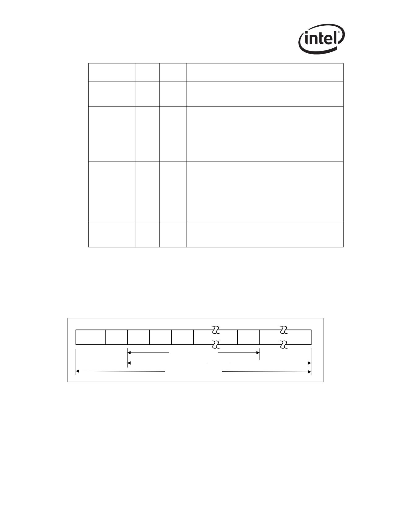
For the 82541xx and 82547GI/EI, carrier extension (through the TCTLCOLD field) provides a
method to increase the duration of the carrier event to a minimum usable duration in order to meet
a 200 m collision domain objective, even though half-duplex operation is impractical at Gigabit.
Packets that are signaled from the CSMA/CD layer that do not meet the minimum slot time of 512
bytes have extension bytes appended to them in order to meet this minimum slot time requirement.
The extension bytes are defined within the context of the frame encapsulation discussion of the
802.3z standard and are recognized by 802.3z compliant devices. Refer to Figure 13-1
Preamble
SFD
DA
SA
T/L
Data/Pad
FCS
Extension
Minimum Frame Size
Slot Time
Duration of Carrier Event
Figure 13-1. Carrier Extended Frame Format (82541xx and 82547GI/EI)
13.4.34
Transmit IPG Register
TIPG (00410;R/W)
This register controls the IPG (Inter Packet Gap) timer for the Ethernet controller.
312

Register Descriptions
Table 13-77. TIPG Register Bit Description
31
30
29
20
19
10
9
0
Reserved
IPGR2
IPGR1
IPGT
Initial
Field
Bit(s)
Description
Value
IPG Transmit Time
Specifies the IPG time for back-to-back packet transmissions
Measured in increments of the MAC clock:
•
8 ns MAC clock when operating @ 1 Gbps.
•
80 ns MAC clock when operating @ 100 Mbps.
•
800 ns MAC clock when operating @ 10 Mbps.
To calculate the actual IPG value for TBI applications, a value of
10 (6 for the 82544GC/EI) should be added to the IPGT value.
IPGT
9:0
X
For the IEEE 802.3 standard IPG value of 96-bit time, the value
that should be programmed into IPGT is 10 (6 for the 82544GC/
EI).
To calculate the IPG value for 10/100/1000BASE-T applications,
a value of four should be added to the IPGT value as four clocks
are used by the MAC as internal overhead. The value that
should be programmed into IPGT is 10 (8 for the 82544GC/EI).
These values are recommended to assure that the minimum
IPG gap is met under all synchronization conditions.
IPG Receive Time 1
Specifies the length of the first part of the IPG time for non back-
to-back transmissions. During this time, the internal IPG counter
restarts if any carrier event occurs. Once the time specified in
IPGR1 has elapsed, carrier sense does not affect the IPG
counter.
According to the IEEE802.3 standard, IPGR1 should be 2/3 of
IPGR2 value.
IPGR1
19:10
X
Measured in increments of the MAC clock:
•
8 ns MAC clock when operating @ 1 Gbps (82544GC/EI
only).
•
80 ns MAC clock when operating @ 100 Mbps
•
800 ns MAC clock when operating @ 10 Mbps.
For IEEE 802.3 minimum IPG value of 96-bit time, the value that
should be programmed into IPGR1 is eight.
IPGR1 is significant only in half-duplex mode of operation.
313

Register Descriptions
Initial
Field
Bit(s)
Description
Value
IPG Receive Time 2
Specifies the total length of the IPG time for non back-to-back
transmissions.
Measured in increments of the MAC clock:
•
8 ns MAC clock when operating @ 1 Gbps (82544GC/EI
only).
•
80 ns MAC clock when operating @ 100 Mbps
IPGR2
29:20
X
•
800 ns MAC clock when operating @ 10 Mbps.
In order to calculate the actual IPG value, a value of six should
be added to the IPGR2 value as six MAC clocks are used by the
MAC for synchronization and internal engines.
For the IEEE 802.3 standard IPG value of 96-bit time, the value
that should be programmed into IPGR2 is six (total IPG delay of
12 MAC clock cycles) According to the IEEE802.3 standard,
IPGR1 should be 2/3 of IPGR2 value.
IPGR2 is significant only in half-duplex mode of operation.
Reserved
Reserved
31:30
X
Read as 0b.
Should be written with 0b for future compatibility.
13.4.35
Adaptive IFS Throttle - AIT
AIFS (00458;R/W)
This register throttles back-to-back transmissions in the transmit packet buffer and delays their
transfer to the CSMA/CD transmit function. As a result, it can be used to delay the transmission of
back-to-back packets on the wire.
For the 82544GC/EI, this register can be used to increase the IPG value between transmitting
back-to-back packets on the wire and between frames while in half-duplex mode.
314

Register Descriptions
Table 13-78. AIFS Register Bit Description
31
16
15
0
Reserved
Adaptive IFS
Initial
Field
Bit(s)
Description
Value
Adaptive IFS Value (82544GC/EI only)
Adaptive IFS throttles back-to-back transmissions in the
transmit packet buffer and delays their transfer to the CSMA/CD
transmit function. Normally, this register should be set to 0b.
However, if additional delay is desired between back-to-back
transmit packets, then this register can be set with a value
greater than zero (0). This feature can be helpful in high collision
half-duplex environments.
In order for AIFS to take effect it should be larger than the
minimum IFS value defined in IEEE 802.3 standard.
AIFS
15:0
0b
AIFS has no effect on transmissions that occur immediately
after receives or transmissions that are not back-to-back. In
addition, it has no effect on re-transmission timing (re-
transmission after collisions).
The AIFS programming value is in units of 8 ns (TX_CLK), and
is 16 bits wide, thus providing greater flexibility and maximum
delay value comparing TIPG.IPGT. The AIFS value is additive to
the TIPG.IPGT value.
Adaptive IFS Value (all remaining Ethernet controllers)
This value is in units of 8 ns.
Reserved
Reserved
31:16
0b
Should be written with 0b.
13.4.36
Transmit Descriptor Base Address Low
TDBAL (03800h; R/W)
This register contains the lower bits of the 64-bit transmit Descriptor base address. The base
register indicates the start of the circular transmit descriptor queue. Since each descriptor is 16 bits
in length, the lower four bits are ignored as the Transmit Descriptor Base Address must point to a
16-byte aligned block of data.
Table 13-79. TDBAL Register Bit Description
31
4 3
0
TDBAL
0
315

Register Descriptions
Initial
Field
Bit(s)
Description
Value
Zero Value
ZERO
3:0
0b
This field is ignored on write and reads as 0b.
Transmit Descriptor Base Address Low [31:4]
TDBAL
31:4
X
This register indicates lower 32 bits of the start address for the
transmit descriptor ring buffer.
13.4.37
Transmit Descriptor Base Address High
TDBAH (03804h; R/W)
This register contains the upper 32 bits of the 64-bit transmit Descriptor base address.
Table 13-80. TDBAH Register Bit Description
31
0
TDBAH
Initial
Field
Bit(s)
Description
Value
Transmit Descriptor Base Address [63:32]
TDBAH
31:0
X
This register indicates upper 32 bits of the start address for the
transmit descriptor ring buffer.
13.4.38
Transmit Descriptor Length
TDLEN (03808h; R/W)
This register determines the number of bytes allocated to the transmit descriptor circular buffer.
This value must be a multiple of 128 bytes (the maximum cache line size). Since each descriptor is
16 bits in length, the total number of receive descriptors is always a multiple of eight.
Table 13-81. TDLEN Register Bit Description
31
20 19
7 6
0
Reserved
LEN
0
Initial
Field
Bit(s)
Description
Value
ZERO
6:0
0b
Ignore on write. Reads back as 0b.
316
Register Descriptions
Descriptor Length.
LEN
19:7
0b
Number of bytes allocated to the transmit descriptor circular
buffer.
Reserved
Reserved
31:20
0b
Reads as 0b. Should be written with 0b for future compatibility.
13.4.39
Transmit Descriptor Head
TDH (03810h; R/W)
This register contains the head pointer for the transmit descriptor ring. It holds a value that is an
offset from the base, and indicates the in-progress descriptor. It points to a 16-byte datum.
Hardware controls this pointer. The only time that software should write to this register is after a
reset (TCTL.RST or CTRL.RST) and before enabling the transmit function (TCTL.EN). If
software were to write to this register while the transmit function was enabled, the on-chip
descriptor buffers can be invalidated and indeterminate operation can result. Reading the transmit
descriptor head to determine which buffers have been used (and can be returned to the memory
pool) is not reliable.
Table 13-82. TDH Register Bit Description
31
16 15
0
Reserved
TDH
317

Register Descriptions
Initial
Field
Bit(s)
Description
Value
TDH
15:0
0b
Transmit Descriptor Head
Reserved
Reserved
31:16
0b
Reads as 0b. Should be written with 0b for future compatibility.
13.4.40
Transmit Descriptor Tail
TDT (03818h; R/W)
This register contains the tail pointer for the transmit descriptor ring. It holds a value that is an
offset from the base, and indicates the location beyond the last descriptor hardware can process.
This is the location where software writes the first new descriptor. It points to a 16-byte datum.
Software writes the tail pointer to add more descriptors to the transmit ready queue. Hardware
attempts to transmit all packets referenced by descriptors between head and tail.
Table 13-83. TDT Register Bit Description
31
16 15
0
Reserved
TDT
Initial
Field
Bit(s)
Description
Value
TDT
15:0
0b
Transmit Descriptor Tail
Reserved
Reserved
31:16
0b
Reads as 0b. Should be written to 0b for future compatibility.
13.4.41
Transmit Interrupt Delay Value
TIDV (03820h; R/W)
This register contains the transmit interrupt delay value. It determines the amount of time that
elapses between writing back a descriptor that has Report Status (RS) [or Report Packet Sent (RPS)
for the 82544GC/EI] and Interrupt Delay Enable (IDE) set in the transmit descriptor and when the
IMS.TXDW (Transmit Descriptor Written Back) interrupt bit is set. Counts are in units of 1.024
s. A value of 0b is not allowed. The TIDV value is used to force timely write-back of descriptors
as well. The first packet after timer initialization starts the timer. Timer expiration flushes any
accumulated descriptors and sets an interrupt event (TXDW).
318

Register Descriptions
Table 13-84. TIDV Register Bit Description
31
16 15
0
Reserved
IDV
Initial
Field
Bit(s)
Description
Value
Interrupt Delay Value
IDV
15:0
X
Counts in units of 1.024 s. A value of 0bis not allowed.
Reserved
Reserved
31:16
0b
Reads as 0b. Should be written to 0b for future compatibility.
13.4.42
TX DMA Control (82544GC/EI only)
TXDMAC (03000h; R/W)
This register controls the transmit DMA pre-fetching and preemption abilities.
Table 11-85. TXDMAC Register Bit Description
31
1
0
Reserved
DPP
Initial
Field
Bit(s)
Description
Value
Disable packet prefetching
When set, prevents the Ethernet controller from starting a
DPP
0
1
transmit descriptor data fetch before it has finished processing
the previous descriptor. In general, performance increases
when this bit is set to 0b.
Reserved
Reserved
31:1
0
Reads as 0b. Should be written to 0b for future compatibility.
13.4.43
Transmit Descriptor Control
TXDCTL (03828h; R/W)
This register controls the fetching and write back of transmit descriptors. The three threshold
values provided are used to determine when descriptors are read from and written to host memory.
The values can be in units of cache lines or descriptors (each descriptor is 16 bytes).
319

Register Descriptions
Table 13-86. TXDCTL Register Bit Description
31
25
24
23
22 21
16 15
14 13
8 7
6 5
0
LWTHRESH
GRAN
RSV
WTHRESH
RSV
HTHRESH
RSV
PTHRESH
RSV1
1.
82544GC/EI only.
Initial
Field
Bit(s)
Description
Value
Prefetch Threshold
Used to control when a pre-fetch of descriptors is considered.
This threshold refers to the number of valid, unprocessed
transmit descriptors the Ethernet controller has in its on-chip
buffer. If this number drops below PTHRESH, the algorithm
PTHRESH
5:0
0b
considers prefetching descriptors from host memory. This fetch
does not happen unless there are at least TXDCTL.HTHRESH
valid descriptors in host memory to fetch. Value of PTHRESH
can be in either cache line units, or based on number of
descriptors based on TXDCTL.GRAN.
Reserved
Reserved
7:6
0b
Reads as 0b. Should be written as 0b for future compatibility.
Host Threshold
Provides the threshold of the valid descriptors in host memory A
descriptor prefetch is performed each time enough valid
descriptors (TXDCTL.HTHRESH) are available in host memory,
no other DMA activity of greater priority is pending (descriptor
HTHRESH
15:8
0b
fetches and write backs or packet data transfers) and the number
of transmit descriptors the Ethernet controller has on its on-chip
buffers drops below TXDCTL.PTHRESH. The value of
HTHRESH can be in either cache line units, or based on number
of descriptors based on TXDCTL.GRAN.
Reserved
Reserved
15:14
0b
Reads as 0b. Should be written as 0b for future compatibility.
Write Back Threshold
WTHRESH controls the write back of processed transmit
descriptors. This threshold refers to the number of transmit
descriptors in the Ethernet controller’s on-chip buffer which are
ready to be written back to host memory. In the absence of
external events (explicit flushes), the write back occurs only after
WTHRESH
21:16
0b
more than WTHRESH descriptors are available for write back.
WTHRESH must contain a non-zero value to take advantage of
the write back bursting capabilities of the Ethernet controller. A
value of 0b causes the descriptors to be written back as soon as
they are processed.
The value of WTHRESH can be in either cache line units, or
based on number of descriptors based on RXDCTL.GRAN.
320

Register Descriptions
Initial
Field
Bit(s)
Description
Value
Reserved
Reserved
23:22
0b
Reads as 0b. Should be written as 0b for future compatibility.
Granularity
Set the values of PTHRESH, HTHRESH and WTHRESH in units
GRAN
24
0b
of cache lines or descriptors (each descriptor is 16 bytes)
1b = Descriptor granularity.
0b = Cache line granularity.
Transmit descriptor Low Threshold
Interrupt asserted when the number of descriptors pending
LWTHRESH1
31:25
0h
service in the transmit descriptor queue (processing distance
from the TDT) drops below this threshold.
1.
Not applicable to the 82544GC/EI.
Since write back of transmit descriptors is optional (under the control of RS bit in the descriptor),
not all processed descriptors are counted with respect to WTHRESH. Descriptors start accumu-
lating after a descriptor with RS (or RPS for the 82544GC/EI) is set. Furthermore, with transmit
descriptor bursting enabled, some descriptors are written back that did not have RS (or RPS for the
82544GC/EI) set in their respective descriptors.
LWTHRESH (not applicable to the 82544GC/EI) controls the number of pre-fetched transmit
descriptors at which a transmit descriptor-low interrupt (ICR.TXD_LOW) is reported. This can
enable software to operate more efficiently by maintaining a continuous addition of transmit work,
interrupting only when the hardware nears completion of all submitted work. LWTHRESH
specifies a multiple of eight descriptors. An interrupt is asserted when the number of descriptors
available transitions from (threshold level=8*LWTHRESH)+1 to (threshold
level=8*LWTHRESH). Setting this value to 0b causes this interrupt to be generated only when the
transmit descriptor cache becomes completely empty.
13.4.44
Transmit Absolute Interrupt Delay Value1
TADV (0382Ch; RW)
31
16
15
0
Reserved
IDV
Initial
Field
Bit(s)
Description
Value
Interrupt Delay Value
IDV
15:0
0b
Counts in units of 1.024 s. (0b = disabled)
Reserved
31:16
0b
Reads as 0b. Should be written to 0b for future compatibility.
1.
Not applicable to the 82544GC/EI.
321
Register Descriptions
The transmit interrupt delay timer (TIDV) can be used to coalesce transmit interrupts. However, it
might be necessary to ensure that no completed transmit remains unnoticed for too long an interval
in order ensure timely release of transmit buffers. This register can be used to ENSURE that a
transmit interrupt occurs at some predefined interval after a transmit is completed. Like the
delayed-transmit timer, the absolute transmit timer ONLY applies to transmit descriptor operations
where (a) interrupt-based reporting is requested (RS set) and (b) the use of the timer function is
requested (IDE is set).
This feature operates by initiating a countdown timer upon successfully transmitting the buffer.
When the timer expires, a transmit-complete interrupt (ICR.TXDW) is generated. The occurrence
of either an immediate (non-scheduled) or delayed transmit timer (TIDV) expiration interrupt halts
the TADV timer and eliminates any spurious second interrupts.
Setting the value to 0b disables the transmit absolute delay function. If an immediate (non-
scheduled) interrupt is desired for any transmit descriptor, the descriptor IDE should be set to 0b.
13.4.45
TCP Segmentation Pad And Minimum Threshold
TSPMT (03830h; RW)
This register specifies fields affecting the Ethernet controller behavior during TCP Segmentation
operations. Values are specified in bytes. For normal (non TCP Segmentation) operations, the
Ethernet controller’s transmit DMA never begins servicing an individual data descriptor unless the
transmit Packet Buffer has sufficient room to accept all of the data associated with the descriptor.
However, for TCP Segmentation operations, it might be desirable to use a data descriptor that
refers to a larger contiguous buffer in host memory than is actually allocated for the transmit Packet
Buffer. For TCP segmentation, then, the transmit DMA is able to initiate smaller transfers than the
entire descriptor’s data length field.
31
16
15
0
TSPBP
TSMT
Initial
Field
Bit(s)
Description
Value
TSMT
15:0
0400h
TCP Segmentation Minimum Transfer
TSPBP
31:16
0100h
TCP Segmentation Packet Buffer Padding
322
Register Descriptions
When performing TCP segmentation, the packet prototype header initially transferred by DMA is
stored internally and updated as each packet of the TCP segmentation operation is composed. As
data for subsequent TCP segments is DMA’d into the Ethernet controller, the frame header for each
segment is dynamically inserted in front of the frame payload data stream prior to being written to
the packet buffer. In order to obtain the most efficient use of burst DMA operations, the transmit
DMA attempts to fetch as much data from a descriptor as possible, rather than limiting itself to
bursting each data segment individually. However, to do this, sufficient packet buffer space must
be reserved to account for all headers are inserted into the fetched data stream, as the burst might
span multiple data segments. The calculation of how much packet buffer space should be reserved
is dependent on the MSS being used, the maximum-sized data buffer pointed to by a descriptor,
and the current header size. This calculation is left to software to pre-calculate for the worst-case
usage. The TSPBP register allows configuration of this buffer space that must be reserved as “pad”
for worst-case header insertion. To ensure that this value does not prevent descriptors from being
serviced at all, it is necessary that the transmit packet buffer allocation should be larger than the
sum of (maximum TCP HDRLEN + maximum MSS + TMPBP + 80 bytes).
Because the DMA attempts to issue burst fetches for a much data as possible, it is possible for the
transmit DMA to cause the transmit packet buffer to approach fullness (less the pad specified).
However, if the packet buffer empties slightly, the transmit DMA could initiate a series of small
transfers. To further optimize the efficiency of the transmit DMA during TCP segmentation
operation, the TSMT register allows configuration of the minimum number of bytes that the DMA
should attempt to transfer in a single burst operation. The transmit DMA uses this value to refrain
from issuing a burst read until at least TSMT bytes of data from the current data descriptor can be
stored in the packet buffer. This check is ignored if, after a series of DMA operations, the
descriptor contains a smaller number of unfetched data bytes. To ensure that this minimum
threshold does not prevent descriptors from being serviced at all, it is necessary that the transmit
packet buffer allocation should be larger than the sum of (TSMT + TSPBP + 80 bytes). To ensure
compliance with PCI-X specifications, this value should not be programmed to exceed 4 KB (the
largest single-burst transfer allowed by PCI-X).
The transmit DMA further refrains from initiating service of a new data descriptor unless sufficient
packet buffer space exists to at least fetch a full data segment or complete a partially-fetched
segment.
323

Register Descriptions
13.4.46
Receive Descriptor Control
RXDCTL (02828h; R/W)
This register controls the fetching and write-back of receive descriptors. The three threshold values
are used to determine when descriptors are read from and written to host memory. The values can
be in units of cache lines or descriptors (each descriptor is 16 bytes) based on the GRAN flag. If
GRAN = 0b (specifications are in cache-line granularity), the thresholds specified (based on the
cacheline size specified in the PCI header CLS field) must not represent greater than 31
descriptors.
Table 13-87. RXDCTL Register Bit Description
31
25
24
23
22 21
16 15
14 13
8 7
6 5
0
Reserved
GRAN
RSV
WTHRESH
RSV
HTHRESH
RSV
PTHRESH
Initial
Field
Bit(s)
Description
Value
Prefetch Threshold
Used to control when a prefetch of descriptors is considered. This
threshold refers to the number of valid, unprocessed receive
descriptors the Ethernet controller has in its on-chip buffer. If this
number drops below PTHRESH, the algorithm considers
PTHRESH
5:0
0b
prefetching descriptors from host memory. This fetch does not
happen unless there are at least RXDCTL.HTHRESH valid
descriptors in host memory to fetch. Value of PTHRESH can be in
either cache line units, or based on number of descriptors based
on RXDCTL.GRAN.
Reserved
RSV
7:6
0b
Reads as 0b.
Should be written as 0b for future compatibility.
Host Threshold
Provides the threshold of the valid descriptors in host memory.
A descriptors prefetch is performed each time enough valid
descriptors (TXDCTL.HTHRESH) are available in host memory,
no other DMA activity of greater priority is pending (descriptor
HTHRESH
13:8
0b
fetches and write backs or packet data transfers) and the number
of receive descriptors the Ethernet controller has on its on-chip
buffers drops below RXDCTL.PTHRESH. Value of HTHRESH
can be in either cache line units, or based on number of
descriptors based on RXDCTL.GRAN.
Reserved
RSV
15:14
0b
Reads as 0b.
Should be written as 0b for future compatibility.
324

Register Descriptions
Initial
Field
Bit(s)
Description
Value
Write Back Threshold
WTHRESH controls the write back of processed receive
descriptors. This threshold refers to the number of receive
descriptors in the Ethernet controller’s on-chip buffer which are
ready to be written back to host memory. In the absence of
external events (explicit flushes), the write back occurs only after
WTHRESH
21:16
1b
more than WTHRESH descriptors are available for write back.
WTHRESH must contain a non-zero value to take advantage of
the write back bursting capabilities of the Ethernet controller.
A value of 1b causes the descriptors to be written back as soon
as one cache line is available. A value of WTHRESH can be in
either cache line units, or based on number of descriptors based
on RXDCTL.GRAN.
Reserved
RSV
23:22
0b
Reads as 0b.
Should be written as 0b for future compatibility.
Granularity
Set the values of PTHRESH, HTHRESH and WTHRESH in units
GRAN
24
1b
of cache lines or descriptors (each descriptor is 16 bytes)
0b = Cache line granularity.
1b = Descriptor granularity.
Reserved
Reserved
31:25
0b
Reads as 0b.
Should be written as 0b for future compatibility.
13.4.47
Receive Checksum Control
RXCSUM (05000h; R/W)
The Receive Checksum Control register controls the receive checksum offloading features of the
Ethernet controller. The Ethernet controller supports the offloading of three receive checksum
calculations: the Packet Checksum, the IP Header Checksum, and the TCP/UDP Checksum.
The frame types that are supported:
• Ethernet II
• Ethernet SNAP
Table 13-88. RXCSUM Register Bit Description
31:11
10
9
8
7
0
RSV
IPV6OFL1
TUOFLD
IPOFLD
PCSS
1.
Not applicable to the 82544GC/EI.
325

Register Descriptions
Initial
Field
Bit(s)
Description
Value
Packet Checksum Start
Controls the starting byte for the Packet Checksum
calculation. The Packet Checksum is the one’s complement
over the receive packet, starting from the byte indicated by
RXCSUM.PCSS (0b corresponds to the first byte of the
packet), after stripping. For example, for an Ethernet II frame
encapsulated as an 802.3ac VLAN1 packet and with
RXCSUM.PCSS set to 14, the packet checksum would
PCSS
7:0
0b
include the entire encapsulated frame, excluding the 14-byte
Ethernet header (DA,SA,Type/Length) and the 4-byte VLAN
tag. The Packet Checksum does not include the Ethernet
CRC if the RCTL.SECRC bit is set. Software must make the
required offsetting computation (to back out the bytes that
should not have been included and to include the pseudo-
header) prior to comparing the Packet Checksum against the
TCP checksum stored in the packet.
IP Checksum Off-load Enable
RXCSUM.IPOFLD is used to enable the IP Checksum
offloading feature. If RXCSUM.IPOFLD is set to 1b, the
Ethernet controller calculates the IP checksum and indicates
a pass/fail indication to software through the Checksum Error
IPOFLD
8
0b
bit (CSE) in the ERROR field to the receive descriptor. If both
RXCSUM.IPOFLD and RXCSUM.TUOFLD are set, the
Checksum Error bit (CSE) is set if either checksum was
incorrect. If neither RSCSUM.IPOFLD nor
RXCSUM.TUOFLD is set, the Checksum Error bit (CSE) is
be 0b for all packets.
TCP/UDP Checksum Off-load Enable
RXCSUM.TUOFL is used to enable the TCP/UDP Checksum
off-loading feature. When set to 1b, the Ethernet controller
calculates the TCP or UDP checksum and indicate a pass/fail
indication to software through the Checksum Error bit (CSE).
TUOFLD
9
0b
If both RXCSUM.TUOFLD and RXCSUM.TUOFLD are set,
the Checksum Error bit (CSE) is set if either checksum was
incorrect. If neither RXCSUM.IPOFLD nor
RXCSUM.TUOFLD is set, the Checksum Error bit (CSE) is
0b for all packets.
IPv6 Checksum Offload Enable
If IPV6OFL is set to 1b, hardware parses IPv6 headers when
IPV6OFL2
10
0b
parsing a receive packet. This applies to checksum offloading
only.
Reserved
Reserved
31:11
0b
Reads as 0b. Should be written with 0b for future
compatibility.
1.
Not applicable to the 82541ER.
2.
Not applicable to the 82544GC/EI.
326
Register Descriptions
13.5
Filter Registers
This section contains detailed descriptions for those registers associated with the Ethernet
controller’s address filter capabilities.
13.5.1
Multicast Table Array
MTA[127:0] (05200h-053FCh; R/W)
The multicast table array is a way to extend address filtering beyond the 16 perfect in the Receive
Address Register (RAR). Note that the MTA is an imperfect filter that allows you to filter on 4096
similar addresses using a much smaller data structure than would be required to store all 4096
addresses in a linear table such as a perfect filter.
The Ethernet controller provides a 4096-bit vector multicast table array that is used when all the 16
perfect filters in the Receive Address Registers (RAR) are used. There is one register per 32 bits of
the Multicast Address Table for a total of 128 registers (thus the MTA[127:0] designation). The
size of the word array depends on the number of bits implemented in the multicast address table.
Software must mask to the desired bit on reads and supply a 32-bit word on writes. Accesses to this
table must be 32-bit.
Table 13-89. MTA Register Bit Description
Initial
Field
Bit(s)
Description
Value
Multicast bit vector specifying 32 bits in the multicast address filter
MC Bit Vector
31:0
X
table.
The operating system provides a list of addresses that it would like to respond to. The driver fills in
the Receive Address Registers (RAR) first, as these are exact matching addresses. If the OS
provides more than the 16 addresses available in RARs, the overflow is put into the MTA. The
MTA does not match the exact address, but a subset of the address. Each address filtered on is
represented by a single bit within the MTA table. Software needs to do the same calculations that
hardware does when checking against the MTA, so it can program the appropriate bit in the MTA.
When the hardware receives an address, it goes through the RARs, and if it does not find a match,
it does the same calculations that are described below on the address that it was given and only
checks one bit in the MTA. If that bit is set, it allows the packet to pass. If that bit is not set, it drops
the packet.
The calculation to find that bit is as follows (using the example of 12:34:56:78:9A:BCh):
Check the RCTL bits 13:12 to see what they are set to. In this example it is 00h that means that
we only look at bits 47:36. This corresponds to 0BC9h in the example address (assuming that
in your example 12 is the least significant byte and 0BCh is the most significant byte). The
way the address is stored in memory is the same that it would be going out on the wire, which
is the least significant byte is the first on the wire, so it looks like this:
BC:9A:78:56:34:12h so that the LSB (12) goes on the wire first. Breaking 0BC9h down into a
word:
0BC9h = 0000_1011_1100_1001b
327
Register Descriptions
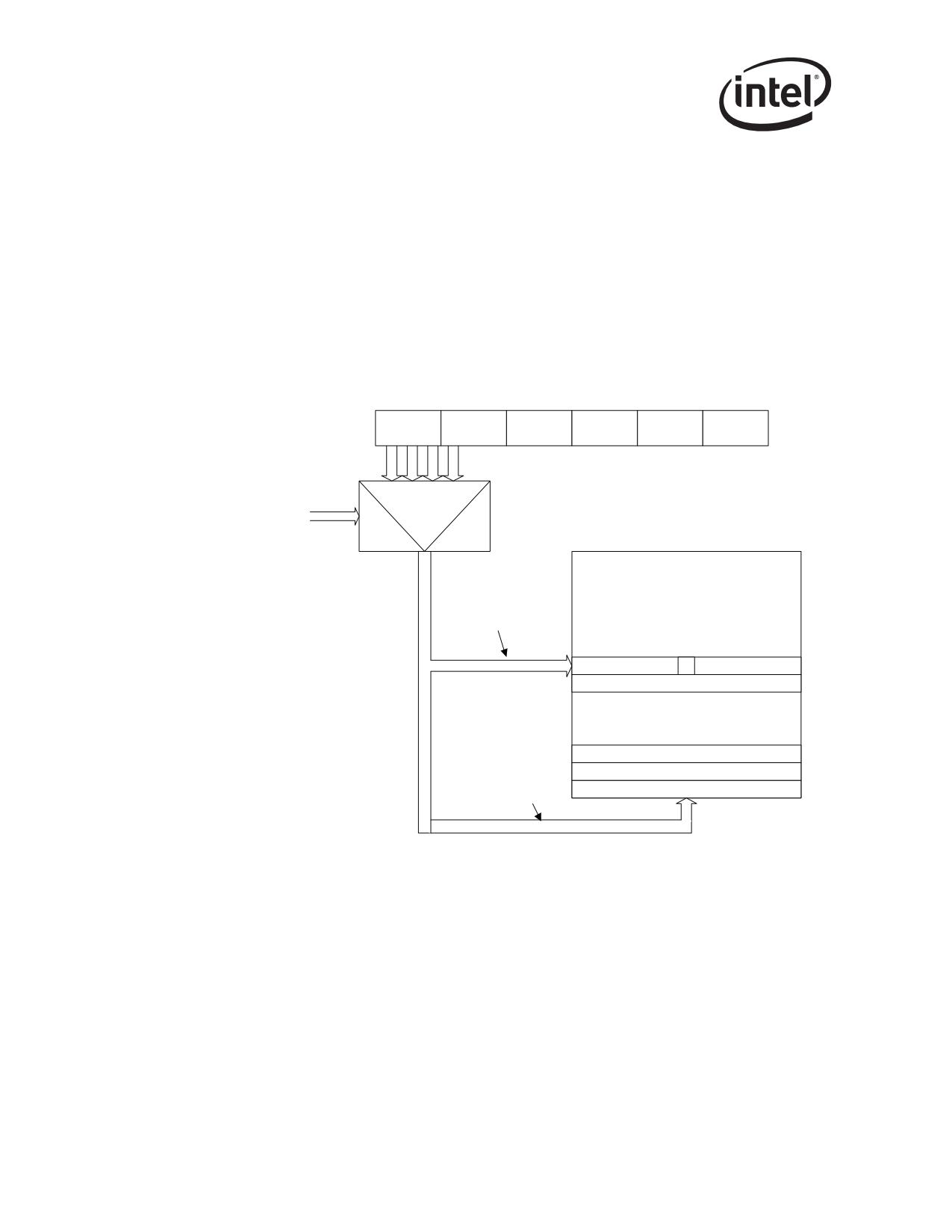
Of the 16 bits, look at bits 11:5, starting from zero. These seven bits corresponds to the row
within the MTA table (the MTA has 128 rows which require seven bits to define). In the
example, bits 11:5 are 1011110b. This corresponds to row 94.
Of these 16 bits, count out the first five bits, again starting from bit zero. These first five bits
correspond to the bit within the row (the MTA is 32 bits wide which require five bits to
define). In the example this is 01001b. This corresponds to bit nine. This is the offset within
the row.
Therefore, software needs to set bit nine of row 94 in the MTA. If the OS removes this address
from the filter list, software would need to clear this bit. This is the same bit that the hardware
would check if it received a packet with an address of xx:xx:xx:xx:9x:BCh.
Destination Address
47:40
39:32
31:24
23:16
15:8
7:0
bank[1:0]
Multicast Table
word
Array 32 x 128
(4096-bit vector)
?
pointer[11:5]
bit
pointer[4:0]
Figure 13-2. Multicast Table Array
328

Register Descriptions
13.5.2
Receive Address Low
RAL (05400h + 8*n; R/W)
16 registers contain the lower bits of the 48-bit Ethernet address. All 32 bits are valid. Software can
access the High and Low registers as a register pair if it can perform a 64-bit access to the PCI bus.
The addresses stored in these registers are used for unicast/multicast address filtering.
The first receive address register (RAL0, RAH0) is also used for exact match PAUSE frame
checking (Valid PAUSE packet that is addressed to the station’s address). Therefore, RAL0 and
RAH0 always should be used to store the individual Ethernet MAC address of the Ethernet
controller.
Table 13-90. RAL Register Bit Description
31
0
RAL
Initial
Field
Bit(s)
Description
Value
Receive address low
Contains the lower 32-bit of the 48-bit Ethernet address.
RAL
31:0
X
RAL0 should be used to store the lower 32-bit of the Ethernet
controller’s Ethernet MAC address.
13.5.3
Receive Address High
RAH (05404h + 8n; R/W)
16 registers contain the upper bits of the 48-bit Ethernet address. The complete address is {RAH,
RAL}. Software can access the High and Low registers as a register pair if it can perform a 64-bit
access to the PCI bus. The addresses stored in these registers are used for unicast/multicast address
filtering.
The first receive address register (RAL0, RAH0) is also used for exact match Pause frame
checking (Valid Pause packet that is addressed to the station’s address). Therefore, RAL0 and
RAH0 always should be used to store the individual Ethernet MAC address of the Ethernet
controller.
Note: When writing to this register, always write low-to-high. When clearing this register, always clear
high-to-low.
329

Register Descriptions
Table 13-91. RAH Register Bit Description
31
30
18 17
16 15
0
AV
Reserved
AS
RAH
Initial
Field
Bit(s)
Description
Value
Receive address High
Contains the upper 16 bits of the 48-bit Ethernet address.
RAH
15:0
X
RAH0 should be used to store the upper 16-bit of the Ethernet
controller’s Ethernet MAC address.
Address Select
Selects how the address is to be used in the address filtering.
00b = Destination address (required for normal mode)
AS
17:16
X
01b = Source address
10b = Reserved
11b = Reserved
Reserved
Reserved
30:18
0b
Should be written with 0b to ensure future compatibility.
Reads as 0b.
Address Valid
Determines whether this address is compared against the
incoming packet. When set, the address is valid and is
AV
31
0b
compared against the incoming packet. When cleared, the
address is invalid and is not compared against the received
packet. AV is only cleared by a PCI reset or software reset. This
bit is unchanged by rx_reset.
13.5.4
VLAN Filter Table Array1
VFTA[127:0] (05600h - 057FCh; R/W)
The Ethernet controller provides a 4096-bit vector VLAN Filter table array. There is one register
per 32 bits of the VLAN Filter Table, for a total of 128 registers (thus the VFTA[127:0]
designation). The size of the word array depends on the number of bits implemented in the VLAN
Filter table. Software must mask to the desired bit on reads, and supply a 32-bit word on writes.
Accesses to this table must be 32-bit.
The algorithm for VLAN filtering using the VFTA is identical to that used for the Multicast Table
Array. Refer to Section 13.5.1 for a block diagram of the algorithm. If VLANs are not used, there is
no need to initialize the VFTA.
1.
Not applicable to the 82541ER.
330

Register Descriptions
Table 13-92. VFTA[127:0] Bit Description
31
0
VLAN Filter Bit Vector
Initial
Field
Bit(s)
Description
Value
Double-word wide bit vector specifying 32 bits in the VLAN
Bit Vector
31:0
X
Filter table.
13.6
Wakeup Registers
13.6.1
Wakeup Control Register
WUC (05800h; R/W)
This register is reset any time LAN_PWR_GOOD is set to 0b. When AUX_POWER equals 0b,
this register is also reset by de-asserting (rising edge) RST#.
31
4
3
2
1
0
Reserved
APMPME
PME_S
PME_EN
APME
Initial
Field
Bit(s)
Description
Value
Advance Power Management Enable
APME
0
0b
If set to 1b, APM Wakeup is enabled.
Note: Always 0b for the 82541ER.
PME_En
This read/write bit is used by the driver to access the PME_En
PME_En
1
0b
bit of the Power Management Control / Status Register
(PMCSR) without writing to the PCI configuration space.
Note: Do not set this bit for the 82541ER.
PME_Status
This bit is set when the Ethernet controller receives a wakeup
PME_Status
2
0b
event. It is the same as the PME_Status bit in the Power
Management Control / Status Register (PMCSR). Writing a 1b
to this bit clears the PME_Status bit in the PMCSR.
331

Register Descriptions
Initial
Field
Bit(s)
Description
Value
Assert PME On APM Wakeup
If set to 1b, the Ethernet controller sets the PME_Status bit in
the Power Management Control / Status Register (PMCSR)
APMPME
3
0b
and asserts PME# when APM Wakeup is enabled and the
Ethernet controller receives a matching Magic Packet. This
field value is loaded from the EEPROM.
Note: Not applicable to the 82541ER.
Reserved
Reserved
27:4
0b
Reads as 0b.
Dynamic Powerdown Mode
Dynamic
28
0b
When programmed to 1b, enables dynamic powerdown
Powerdown1
operation.
Automatic Frequency Select
Determines automatic reduction of MAC frequency in 82541xx
only. Reserved for the 82547GI/EI.
Bit 29 controls MAC speed at 1000 MB. When cleared,
enables the MAC to run at full speed. When set and PCI is
Auto Freq
configured for 33 MHz (82541xx), allows the MAC to run at
30:29
0b2
Select1
half speed.
Bit 30 controls MAC speed at other Ethernet rates. When
cleared, allows the MAC to run at full speed. When set, it
allows the MAC to run at quarter speed.
If both bits are cleared, the MAC frequency select bits control
MAC frequency.
Smart Powerdown MAC
SPM1
31
0b
When programmed to 0b, the MAC operates normally. When
programmed to 1b, the MAC enters smart powerdown mode.
Reserved
Reserved3
31:28
0b
Reads as 0b.
1.
82541xx and 82547GI/EI only.
2.
Loaded from the EEPROM.
3.
Not applicable to the 82541xx and 82547GI/EI.
13.6.2
Wakeup Filter Control Register
WUFC (05808h; R/W)
This register is used to enable each of the pre-defined and flexible filters for wakeup support. A
value of 1b means the filter is turned on, and a value of 0b means the filter is turned off.
This register is reset any time LAN_PWR_GOOD is 0b. When AUX_POWER equals 0b, this
register is also reset by deasserting (rising edge) RST#.
332

Register Descriptions
31
20
19
18
17
16
15
14
8
7
6
5
4
3
2
1
0
Reserved
FLX3
FLX2
FLX1
FLX0
ITCO1
Reserved
IPv62
IPv43
ARP
BC
MC
EX
MAG
LNKC
1.
82541xx and 82547GI/EI only.
2.
Not applicable to the 82544GC/EI.
3.
IP for the 82544GC/EI.
Field
Bit(s)
Initial Value
Description
LNKC
0
0b
Link Status Change Wakeup Enable.
MAG
1
0b
Magic Packet Wakeup Enable.
EX
2
0b
Directed Exact Wakeup Enable.
MC
3
0b
Directed Multicast Wakeup Enable.
BC
4
0b
Broadcast Wakeup Enable.
ARP
5
0b
ARP Request Packet Wakeup Enable.
IPv41
6
0b
Directed IPv4 Packet Wakeup Enable.
IPv62
7
0b
Directed IPv6 Packet Wakeup Enable.
Reserved
14:8
0b
Reserved. Set these bits to 0b.
ITCO3
15
0
Ignore TCO/management packets for wakeup.
FLX0
16
0b
Flexible Filter 0 Enable.
FLX1
17
0b
Flexible Filter 1 Enable.
FLX2
18
0b
Flexible Filter 2 Enable.
FLX3
19
0b
Flexible Filter 3 Enable.
1.
IP for the 82544GC/EI.
2.
Not applicable to the 82544GC/EI.
3.
82541xx and 82547GI/EI only.
13.6.3
Wakeup Status Register
WUS (05810h; R)
This register is used to record statistics about all wakeup packets received. If a packet matches
multiple criteria then multiple bits could be set. Writing a 1b to any bit clears that bit.
This register is not cleared when RST# is asserted. It is only cleared when LAN_PWR_GOOD is
de-asserted or when cleared by the driver software.
333

Register Descriptions
31
20
19
18
17
16
15
8
7
6
5
4
3
2
1
0
Reserved
FLX3
FLX2
FLX1
FLX0
Reserved
IPv61
IPv42
ARP
BC
MC
EX
MAG
LNKC
1.
Not applicable to the 82544GC/EI.
2.
IP for the 82544GC/EI.
Field
Bit(s)
Initial Value
Description
LNKC
0
0b
Link Status Change.
MAG
1
0b
Magic Packet Received.
Directed Exact Packet Received
EX
2
0b
The packet’s address matched one of the 16 pre-programmed
exact values in the Receive Address registers.
Directed Multicast Packet Received
MC
3
0b
The packet was a multicast packet whose hashed to a value
that corresponded to a 1 bit in the Multicast Table Array.
BC
4
0b
Broadcast Packet Received.
ARP
5
0b
ARP Request Packet Received.
IPv41
6
0b
Directed IPv4 Packet Received.
IPv62
7
0b
Directed IPv6 Packet Received.
FLX0
16
0b
Flexible Filter 0 Match.
FLX1
17
0b
Flexible Filter 1 Match.
FLX2
18
0b
Flexible Filter 2 Match.
FLX3
19
0b
Flexible Filter 3 Match.
1.
IP for the 82544GC/EI.
2.
Not applicable to the 82544GC/EI.
334

Register Descriptions
13.6.4
IP Address Valid
IPAV (5838h; R/W)
The IP Address Valid indicates whether the IP addresses in the IP Address Table are valid.
The valid bits are reset any time LAN_PWR_GOOD is 0b. When AUX_POWER equals 0b, the
valid bits are also reset by deasserting (rising edge) RST#.
31
17
16
15
4
3
2
1
0
V43
V42
V41
V40
Reserved
v601
Reserved
V32
V22
V12
V02
1.
Not applicable to the 82544GC/EI.
2.
82544GC/EI only.
Field
Bit(s)
Initial Value
Description
V40
IPv4 Address 0 Valid
0
0b1
V0
IP Address 0 Valid2
V41
IPv4 Address 1 Valid
1
0b
V1
IP Address 1 Valid2
V42
IPv4 Address 2 Valid
2
0b
V2
IP Address 2 Valid2
V43
IPv4 Address 3 Valid
3
0b
V3
IP Address 3 Valid2
V603
16
0b
IPv6 Address 0 Valid
1.
The initial value is loaded from the IP Address Valid bit of the EEPROM’s Management Control Register.
2.
82544GC/EI only.
3.
Not applicable to the 82544GC/EI.
335

Register Descriptions
13.6.5
IPv4 Address Table1
IP4AT (05840h - 05858h; R/W)2
The IPv4 Address Table is used to store the four IP addresses for ARP Request packet and Directed
IP packet wakeup for IPv4.
Note: This table is not cleared by any reset.
DWORD#
Address
31
0
0
5840h
IPV4ADDR01
2
5848h
IPV4ADDR1
3
5850h
IPV4ADDR2
4
5858h
IPV4ADDR3
1.
IPA for the 82544GC/EI.
Field
Dword #
Address
Bit(s)
Initial Value
Description
IPV4ADDR01
0
5840h
31:0
X2
IPv4 Address 0
IPV4ADDR1
2
5848h
31:0
X
IPv4 Address 1
IPV4ADDR2
4
5850h
31:0
X
IPv4 Address 2
IPV4ADDR3
6
5858h
31:0
X
IPv4 Address 3
1.
IPA for the 82544GC/EI.
2.
The first entry is loaded from the EEPROM if the IP Address Valid field of the EEPROM’s Management Control word is 1b
and the IP Address Type field is 0b (IPv4). Otherwise, the value of this register is undefined after reset.
1.
IP Address Table for the 82544GC/EI.
2.
IPAT for the 82544GC/EI.
336

Register Descriptions
13.6.6
IPv6 Address Table1
IP6AT (05880h - 0588Ch; R/W)
The IPv6 Address Table is used to store the IPv6 addresses for ARP Request packet and Directed
IP packet wakeup for IPv6.
Note: This table is not cleared by any reset.
DWORD#
Address
31
0
0
5880h
1
5884h
IPV6ADDR0
2
5888h
3
588Ch
Field
Dword #
Address
Bit(s)
Initial Value1
Description
0
5880h
31:0
X
IPv6 Address 0, bytes 1-4
1
5884h
31:0
X
IPv6 Address 0, bytes 5-8
IPV6ADDR0
2
5888h
31:0
X
IPv6 Address 0, bytes 9-12
3
588Ch
31:0
X
IPv6 Address 0, bytes 16-13
1.
This table is loaded from the EEPROM if the IP Address Valid field of the EEPROM’s Management Control word is 1b and
the IP Address Type field is 0b (IPv4). Otherwise, the value of this register is undefined after reset.
1.
Not applicable to the 82544GC/EI.
337

Register Descriptions
13.6.7
Wakeup Packet Length
WUPL (05900h; R/W)
This register indicates the length of the first wakeup packet received. It is valid if one of the bits in
the Wakeup Status Register (WUSR) is set. It can be written for diagnostic purposes and is not
cleared by any reset.
31
12
11
0
Reserved
Length
Field
Bit(s)
Initial Value
Description
Length of wakeup packet. (If jumbo frames is enabled and the
LEN
11:0
X
packet is longer than 2047 bytes this field is 2047.)
13.6.8
Wakeup Packet Memory (128 Bytes)
WUPM (05A00h - 05A7Ch; R/W)
This register is read-only and it is used to store the first 128 bytes of the wakeup packet for
software retrieval after system wakeup. It can be written for diagnostic purposes and is not cleared
by any reset.
31
0
WUPD
Initial
Field
Bit(s)
Description
Value
WUPD
31:0
X
Wakeup Packet Data
13.6.9
Flexible Filter Length Table
FFLT (05F00h - 05F18h; R/W)
The Flexible Filter Length Table stores the minimum packet lengths required to pass each of the
Flexible Filters. Any packets that are shorter than the programmed length won’t pass that filter.
Each Flexible Filter considers a packet that doesn’t have any mismatches up to that point to have
passed the Flexible Filter when it reaches the required length. It does not check any bytes past that
point.
All reserved fields read as 0b’s and ignore writes.
338

Register Descriptions
Before writing to the Flexible Filter Length Table the driver must first disable the flexible filters by
writing 0b’s to the Flexible Filter Enable bits of the Wakeup Filter Control Register
(WUFC.FLXn).
31
0
31
11
10
0
Reserved
Reserved
Length 0
Reserved
Reserved
Length 1
Reserved
Reserved
Length 2
Reserved
Reserved
Length 3
Field
Dword #
Address
Bit(s)
Initial Value
Description
LEN0
0
5F00h
10:0
0b
Minimum Length for Flexible Filter 0
LEN1
2
5F08h
10:0
0b
Minimum Length for Flexible Filter 1
LEN2
4
5F10h
10:0
0b
Minimum Length for Flexible Filter 2
LEN3
6
5F18h
10:0
0b
Minimum Length for Flexible Filter 3
13.6.10
Flexible Filter Mask Table
FFMT (09000h - 093F8h; R/W)
The Flexible Filter Mask and Table is used to store the four 1-bit masks for each of the first 128
data bytes in a packet, one for each Flexible Filter. If the mask bit is set to 1b, the corresponding
Flexible Filter compares the incoming data byte at the index of the mask bit to the data byte stored
in the Flexible Filter Value Table.
Before writing to the Flexible Filter Mask Table the driver must first disable the flexible filters by
writing 0b’s to the Flexible Filter Enable bits of the Wakeup Filter Control Register
(WUFC.FLXn).
31
0
31
4
3
0
Reserved
Reserved
Byte 0 Mask
Reserved
Reserved
Byte 1 Mask
Reserved
Reserved
Byte 2 Mask
Reserved
Reserved
Byte 126 Mask
Reserved
Reserved
Byte 127 Mask
339

Register Descriptions
Field
Dword #
Address
Bit(s)
Initial Value
Description
MASK0
0
9000h
15:0
X
Mask for Filter [3:0] for Byte 0
MASK1
2
9008h
15:0
X
Mask for Filter [3:0] for Byte 2
MASK2
4
9010h
15:0
X
Mask for Filter [3:0] for Byte 3
MASK127
254
93F8h
15:0
X
Mask for Filter [3:0] for Byte 127
13.6.11
Flexible Filter Value Table
FFVT (09800h - 09BF8h; R/W)
The Flexible Filter Value and Table is used to store the one value for each byte location in a packet
for each flexible filter. If the corresponding mask bit is set to 1b, the Flexible Filter compares the
incoming data byte to the values stored in this table.
Before writing to the Flexible Filter Value Table the driver must first disable the flexible filters by
writing 0b’s to the Flexible Filter Enable bits of the Wakeup Filter Control Register
(WUFC.FLXn).
31
0
31
24
23
16
15
8
7
0
Reserved
Byte0: Value3
Value2
Value1
Value0
Reserved
Byte1: Value3
Value2
Value1
Value0
Reserved
Byte2: Value3
Value2
Value1
Value0
Reserved
Byte127: Value3
Value2
Value1
Value0
Field
Dword #
Address
Bit(s)
Initial Value
Description
MASK0
0
9800h
15:0
X
Mask for Filter [3:0] for Byte 0
MASK1
2
9808h
15:0
X
Mask for Filter [3:0] for Byte 2
MASK2
4
9810h
15:0
X
Mask for Filter [3:0] for Byte 3
MASK127
254
9BF8h
15:0
X
Mask for Filter [3:0] for Byte 127
13.7
Statistics Registers
All statistics registers are implemented as 32-bit registers. 64-bit accesses to these registers must
have the upper byte enables de-asserted. 32-bit registers with addresses not on a quadword
boundary cannot be accessed through a 64-bit access.
Registers that count octets make up 64-bit registers.
340

Register Descriptions
All Statistics registers reset when read. 64-bit registers reset whenever the upper 32 bits are read. In
addition, they stick at FFFFh_FFFFh when the maximum value is reached.
The Statistics registers are not hardware initialized. Their default value is unknown. Software
should read the contents of all registers in order to clear them prior to enabling the receive and
transmit channels.
Note: For the receive statistics, it should be noted that a packet is indicated as “received” if it passes the
device filters, and it is placed in the packet buffer memory. A packet does not have to be transferred
to host memory in order to be counted as “received.”
13.7.1
CRC Error Count
CRCERRS (04000h; R)
Counts the number of receive packets with CRC errors. In order for a packet to be counted in this
register, it must pass address filtering and must be 64 bytes or greater (from <Destination Address>
through <CRC>, inclusively) in length. If receives are not enabled, then this register does not
increment.
Table 13-93. CRCERRS Register Bit Description
31
0
CEC
Initial
Field
Bit(s)
Description
Value
CEC
31:0
0b
CRC error count
13.7.2
Alignment Error Count
ALGNERRC (04004h; R)
Counts the number of receive packets with alignment errors (the packet is not an integer number of
bytes in length). In order for a packet to be counted in this register, it must pass address filtering
and must be 64 bytes or greater (from <Destination Address> through <CRC>, inclusively) in
length. If receives are not enabled, then this register does not increment. This register is valid only
in MII mode during 10/100 Mb/s operation.
341

Register Descriptions
Table 13-94. ALGNERRC Register Bit Description
31
0
AEC
Initial
Field
Bit(s)
Description
Value
AEC
31:0
0b
Alignment error count
13.7.3
Symbol Error Count
SYMERRS (04008h; R)
Counts the number of symbol errors between reads. The count increases for every bad symbol
received, whether or not a packet is currently being received and whether or not the link is up. This
register only increments in internal SerDes mode (TBI mode for the 82544GC/EI).
Table 13-95. SYMERRS Register Bit Description
31
0
SYMERRS
Initial
Field
Bit(s)
Description
Value
SYMERRS
31:0
0b
Symbol Error Count
13.7.4
RX Error Count
RXERRC (0400Ch; R)
Counts the number of packets received in which I_RX_ER was asserted by the PHY. In order for a
packet to be counted in this register, it must pass address filtering and must be 64 bytes or greater
(from <Destination Address> through <CRC>, inclusively) in length. If receives are not enabled,
then this register does not increment. In internal SerDes mode (TBI mode for the 82544GC/EI),
this register increments on the reception of
/V/ codes.
342

Register Descriptions
Table 13-96. RXERRC Register Bit Description
31
0
RXEC
Initial
Field
Bit(s)
Description
Value
RXEC
31:0
0b
RX error count
13.7.5
Missed Packets Count
MPC (04010h; R)
Counts the number of missed packets. Packets are missed when the receive FIFO has insufficient
space to store the incoming packet. This can be caused because of too few buffers allocated, or
because there is insufficient bandwidth on the PCI bus. Events setting this counter cause RXO, the
Receiver Overrun Interrupt, to be set. This register does not increment if receives are not enabled.
These packets are also counted in the Total Packets Received register as well as in Total Octets
Received.
Table 13-97. MPC Register Bit Description
31
0
MPC
Initial
Field
Bit(s)
Description
Value
MPC
31:0
0b
Missed Packets Count
13.7.6
Single Collision Count
SCC (04014h; R)
This register counts the number of times that a successfully transmitted packet encountered a single
collision. This register only increments if transmits are enabled and the Ethernet controller is in
half-duplex mode.
343

Register Descriptions
Table 13-98. SCC Register Bit Description
31
0
SCC
Initial
Field
Bit(s)
Description
Value
SCC
31:0
0b
Number of times a transmit encountered a single collision.
13.7.7
Excessive Collisions Count
ECOL (04018h; R)
When 16 or more collisions have occurred on a packet, this register increments, regardless of the
value of collision threshold. If collision threshold is set below 16, this counter won’t increment.
This register only increments if transmits are enabled and the Ethernet controller is in half-duplex
mode.
Table 13-99. ECOL Register Bit Description
31
0
ECC
Initial
Field
Bit(s)
Description
Value
ECC
31:0
0b
Number of packets with more than 16 collisions.
13.7.8
Multiple Collision Count
MCC (0401Ch; R)
This register counts the number of times that a transmit encountered more than one collision but
less than 16. This register only increments if transmits are enabled and the Ethernet controller is in
half-duplex mode.
344

Register Descriptions
Table 13-100. MCC Register Bit Description
31
0
MCC
Initial
Field
Bit(s)
Description
Value
Number of times a successful transmit encountered multiple
MCC
31:0
0b
collisions.
13.7.9
Late Collisions Count
LATECOL (04020h; R)
Late collisions are collisions that occur after 64-byte time into the transmission of the packet while
working in 10-100 Mb/s data rate, and 512 byte time into the transmission of the packet while
working in the 1000 Mb/s data rate. This register only increments if transmits are enabled and the
device is in half-duplex mode.
Table 13-101. LATECOL Register Bit Description
31
0
LCC
Initial
Field
Bit(s)
Description
Value
LCC
31:0
0b
Number of packets with late collisions.
13.7.10
Collision Count
COLC (04028h; R)
This register counts the total number of collisions that are not late collisions seen by the transmitter.
This register only increments if transmits are enabled and the Ethernet controller is in half-duplex
mode.
Table 13-102. COLC Register Bit Description
31
0
CCC
Initial
Field
Bit(s)
Description
Value
CCC
31:0
0b
Total number of collisions experienced by the transmitter.
345

Register Descriptions
13.7.11
Defer Count
DC (04030h; R)
This register counts defer events. A defer event occurs when the transmitter cannot immediately
send a packet due to the medium being busy either because another device is transmitting, the IPG
timer has not expired, half-duplex deferral events, reception of XOFF frames, or the link is not up.
This register only increments if transmits are enabled. This counter does not increment for
streaming transmits that are deferred due to TX IPG.
Table 13-103. DC Register Bit Description
31
0
CDC
Initial
Field
Bit(s)
Description
Value
CDC
31:0
0b
Number of defer events.
13.7.12
Transmit with No CRS
TNCRS (04034h; R)
This register counts the number of successful packet transmissions in which the internal carrier
sense signal from the PHY was not asserted within one slot time of start of transmission.
The PHY should assert the internal carrier sense signal during every transmission. Failure to do so
may indicate that the link has failed, or the PHY has an incorrect link configuration. This register
only increments if transmits are enabled. This register is not valid in internal SerDes1 mode (TBI
mode for the 82544GC/EI), and is only valid when the Ethernet controller is operating at full
duplex.
Table 13-104. TNCRS Register Bit Description
31
0
TNCRS
Initial
Field
Bit(s)
Description
Value
TNCRS
31:0
0b
Number of transmissions without a CRS assertion from the PHY.
1.
The 82540EP/EM, 82541xx, and 82547GI/EI do not support SerDes functionality.
346

Register Descriptions
13.7.13
Sequence Error Count
SEC (04038h; R)
This register counts sequence error events. The proper sequence of 8b/10b symbols is as follows:
idle, start-of-frame (SOF), data, pad (optional), end-of-frame (EOF), fill (optional), idle. Hardware
increments this counter for any illegal sequence of delimiters. If the link is not up, this register does
not increment. This register is only valid in internal SerDes mode (TBI mode for the 82544GC/
EI).
Table 13-105. SEC Register Bit Description
31
0
SEC
Initial
Field
Bit(s)
Description
Value
SEC
31:0
0b
Number of sequence error events.
13.7.14
Carrier Extension Error Count
CEXTERR (0403Ch; R)
This register counts the number of packets received in which the carrier extension error was
signaled across the internal PHY interface. The PHY propagates carrier extension errors to the
MAC when an error is detected during the carrier extended time of a packet reception. An
extension error is signaled by the PHY by the encoding of 1Fh on the receive data inputs. This
register only increments if receives are enabled and the Ethernet controller is operating at
1000 Mb/s. For example, internal PHY or internal SerDes modes (internal PHY or TBI modes for
the 82544GC/EI).
Table 13-106. CEXTERR Register Bit Description
31
0
CEXTERR
Initial
Field
Bit(s)
Description
Value
CEXTERR
31:0
0b
Number of packets received with a carrier extension error.
347

Register Descriptions
13.7.15
Receive Length Error Count
RLEC (04040h; R)
This register counts receive length error events. A length error occurs if an incoming packet passes
the filter criteria but is undersized or oversized. Packets less than 64 bytes are undersized. Packets
over 1522 bytes are oversized if LongPacketEnable is 0b (RCTL.LPE). If LongPacketEnable
(LPE) is 1b, then an incoming packet is considered oversized if it exceeds 16384 bytes.
If receives are not enabled, this register does not increment. These lengths are based on bytes in
the received packet from <Destination Address> through <CRC>, inclusively.
Table 13-107. RLEC Register Bit Description
31
0
RLEC
Initial
Field
Bit(s)
Description
Value
RLEC
31:0
0b
Number of packets with receive length errors.
13.7.16
XON Received Count
XONRXC (04048h; R)
This register counts the number of valid XON packets received. XON packets can use the global
address, or the station address. This register only increments if receives are enabled.
Table 13-108. XONRXC Register Bit Description
31
0
XONRXC
Initial
Field
Bit(s)
Description
Value
XONRXC
31:0
0b
Number of XON packets received.
348
Register Descriptions
13.7.17
XON Transmitted Count
XONTXC (0404Ch; R)
This register counts the number of XON packets transmitted. These can be either due to a full
queue or due to software initiated action (using TCTL.SWXOFF). This register only increments if
transmits are enabled.
Table 13-109. XONTXC Register Bit Description
31
0
XONTXC
Initial
Field
Bit(s)
Description
Value
XONTXC
31:0
0b
Number of XON packets transmitted.
13.7.18
XOFF Received Count
XOFFRXC (04050h; R)
This register counts the number of valid XOFF packets received. XOFF packets can use the global
address or the station address. This register only increments if receives are enabled.
Table 13-110. XOFFRXC Register Bit Description
31
0
XOFFRXC
Initial
Field
Bit(s)
Description
Value
XOFFRXC
31:0
0b
Number of XOFF packets received.
13.7.19
XOFF Transmitted Count
XOFFTXC (04054h; R)
This register counts the number of XOFF packets transmitted. These can be either due to a full
queue or due to software initiated action (using TCTL.SWXOFF). This register only increments if
transmits are enabled.
349

Register Descriptions
Table 13-111. XOFFTXC Register Bit Description
31
0
XOFFTXC
Initial
Field
Bit(s)
Description
Value
XOFFTXC
31:0
0b
Number of XOFF packets transmitted.
13.7.20
FC Received Unsupported Count
FCRUC (04058h; R)
This register counts the number of unsupported flow control frames that are received.
The FCRUC counter increments when a flow control packet is received that matches either the
reserved flow control multicast address (in FCAH/L) or the MAC station address, and has a
matching flow control type field match (to the value in FCT), but has an incorrect opcode field.
This register only increments if receives are enabled.
Table 13-112. FCRUC Register Bit Description
31
0
FCRUC
Initial
Field
Bit(s)
Description
Value
FCRUC
31:0
0b
Number of unsupported flow control frames received.
13.7.21
Packets Received (64 Bytes) Count
PRC64 (0405Ch; R)
This register counts the number of good packets received that are exactly 64 bytes (from
<Destination Address> through <CRC>, inclusively) in length. Packets that are counted in the
Missed Packet Count register are not counted in this register. This register does not include
received flow control packets and increments only if receives are enabled.
350

Register Descriptions
Table 13-113. PRC64 Register Bit Description
31
0
PRC64
Initial
Field
Bit(s)
Description
Value
PRC64
31:0
0b
Number of packets received that are 64 bytes in length.
13.7.22
Packets Received (65-127 Bytes) Count
PRC127 (04060h; R)
This register counts the number of good packets received that are 65-127 bytes (from <Destination
Address> through <CRC>, inclusively) in length. Packets that are counted in the Missed Packet
Count register are not counted in this register. This register does not include received flow control
packets and increments only if receives are enabled.
Table 13-114. PRC127 Register Bit Description
31
0
PRC127
Initial
Field
Bit(s)
Description
Value
PRC127
31:0
0b
Number of packets received that are 65-127 bytes in length.
13.7.23
Packets Received (128-255 Bytes) Count
PRC255 (04064h; R)
This register counts the number of good packets received that are 128-255 bytes (from
<Destination Address> through <CRC>, inclusively) in length. Packets that are counted in the
Missed Packet Count register are not counted in this register. This register does not include
received flow control packets and increments only if receives are enabled.
351

Register Descriptions
Table 13-115. PRC225 Register Bit Description
31
0
PRC255
Initial
Field
Bit(s)
Description
Value
PRC255
31:0
0b
Number of packets received that are 128-255 bytes in length.
13.7.24
Packets Received (256-511 Bytes) Count
PRC511 (04068h; R)
This register counts the number of good packets received that are 256-511 bytes (from
<Destination Address> through <CRC>, inclusively) in length. Packets that are counted in the
Missed Packet Count register are not counted in this register. This register does not include
received flow control packets and increments only if receives are enabled.
Table 13-116. PRC551 Register Bit Description
31
0
PRC511
Initial
Field
Bit(s)
Description
Value
PRC511
31:0
0b
Number of packets received that are 256-511 bytes in length.
13.7.25
Packets Received (512-1023 Bytes) Count
PRC1023 (0406Ch; R)
This register counts the number of good packets received that are 512-1023 bytes (from
<Destination Address> through <CRC>, inclusively) in length. Packets that are counted in the
Missed Packet Count register are not counted in this register. This register does not include
received flow control packets and increments only if receives are enabled.
352

Register Descriptions
Table 13-117. PRC1023 Register Bit Description
31
0
PRC1023
Initial
Field
Bit(s)
Description
Value
PRC1023
31:0
0b
Number of packets received that are 512-1023 bytes in length.
13.7.26
Packets Received (1024 to Max Bytes) Count
PRC1522 (04070h; R)
This register counts the number of good packets received that are from 1024 bytes to the maximum
(from <Destination Address> through <CRC>, inclusively) in length. The maximum is dependent
on the current receiver configuration and the type of packet being received. If a packet is counted in
Receive Oversized Count, it is not counted in this register (see Section 13.7.36). This register does
not include received flow control packets and only increments if the packet has passed address
filtering and receives are enabled.
Due to changes in the standard for maximum frame size for VLAN tagged frames in IEEE
Standard 802.3, these Ethernet controllers accept packets which have a maximum length of 1522
bytes. The RMON statistics associated with this range has been extended to count 1522-byte long
packets.
Table 13-118. PRC1522 Register Bit Description
31
0
PRC1522
Initial
Field
Bit(s)
Description
Value
PRC1522
31:0
0b
Number of packets received that are 1024-Max bytes in length.
13.7.27
Good Packets Received Count
GPRC (04074h; R)
This register counts the number of good packets received of any legal length. The legal length for
the received packet is defined by the value of LongPacketEnable (CTRL.LPE) (see Section
13.7.15). This register does not include received flow control packets and only counts packets that
pass filtering. This register only increments if receives are enabled. This register does not count
packets counted by the Missed Packet Count (MPC) register.
353

Register Descriptions
Table 13-119. GPRC Register Bit Description
31
0
GPRC
Initial
Field
Bit(s)
Description
Value
GPRC
31:0
0b
Number of good packets received (of any length).
13.7.28
Broadcast Packets Received Count
BPRC (04078h; R)
This register counts the number of good (no errors) broadcast packets received. This register does
not count broadcast packets received when the broadcast address filter is disabled. This register
only increments if receives are enabled.
Table 13-120. BPRC Register Bit Description
31
0
BPRC
Initial
Field
Bit(s)
Description
Value
BPRC
31:0
0b
Number of broadcast packets received.
13.7.29
Multicast Packets Received Count
MPRC (0407Ch; R)
This register counts the number of good (no errors) multicast packets received. This register does
not count multicast packets received that fail to pass address filtering nor does it count received
flow control packets. This register only increments if receives are enabled. This register does not
count packets counted by the Missed Packet Count (MPC) register.
354

Register Descriptions
Table 13-121. MPRC Register Bit Description
31
0
MPRC
Initial
Field
Bit(s)
Description
Value
MPRC
31:0
0b
Number of multicast packets received.
13.7.30
Good Packets Transmitted Count
GPTC (04080h; R)
This register counts the number of good (no errors) packets transmitted. A good transmit packet is
considered one that is 64 or more bytes in length (from <Destination Address> through <CRC>,
inclusively) in length. This does not include transmitted flow control packets. This register only
increments if transmits are enabled.
Table 13-122. GPTC Register Bit Description
31
0
GPTC
Initial
Field
Bit(s)
Description
Value
GPTC
31:0
0b
Number of good packets transmitted.
13.7.31
Good Octets Received Count
GORCL (04088h; R)/GORCH (0408Ch; R)
These registers make up a 64-bit register that counts the number of good (no errors) octets
received. This register includes bytes received in a packet from the <Destination Address> field
through the <CRC> field, inclusively. This register resets each time the upper 32 bits are read
(GORCH).
In addition, it sticks at FFFFh_FFFFh_FFFFh_FFFFh when the maximum value is reached. Only
octets of packets that pass address filtering are counted in this register. This register only
increments if receives are enabled.
These octets do not include octets of received flow control packets.
355

Register Descriptions
Table 13-123. GORCL and GORCH Register Bit Description
31
0
31
0
GORCH
GORCL
Initial
Field
Bit(s)
Description
Value
GORCL
31:0
0b
Number of good octets received - lower 4 bytes.
GORCH
31:0
0b
Number of good octets received - upper 4 bytes.
13.7.32
Good Octets Transmitted Count
GOTCL (04090h; R)/ GOTCH (04094; R)
These registers make up a 64-bit register that counts the number of good (no errors) octets
transmitted. This register resets each time the upper 32 bits are read (GOTCH).
In addition, it sticks at FFFF_FFFF_FFFF_FFFFh when the maximum value is reached. This
register includes bytes transmitted in a packet from the <Destination Address> field through the
<CRC> field, inclusively. This register counts octets in successfully transmitted packets that are 64
or more bytes in length. This register only increments if transmits are enabled.
These octets do not include octets in transmitted flow control packets.
Table 13-124. GOTCL and GOTCH Register Bit Description
31
0
31
0
GOTCH
GOTCL
Initial
Field
Bit(s)
Description
Value
GOTCL
31:0
0b
Number of good octets transmitted - lower 4 bytes.
GOTCH
31:0
0b
Number of good octets transmitted - upper 4 bytes.
13.7.33
Receive No Buffers Count
RNBC (040A0h; R)
This register counts the number of times that frames were received when there were no available
buffers in host memory to store those frames (receive descriptor head and tail pointers were equal).
The packet is still received if there is space in the FIFO. This register only increments if receives
are enabled.
356

Register Descriptions
This register does not increment when flow control packets are received.
Table 13-125. RNBC Register Bit Description
31
0
RNBC
Initial
Field
Bit(s)
Description
Value
RNBC
31:0
0b
Number of receive no buffer conditions.
13.7.34
Receive Undersize Count
RUC (040A4h; R)
This register counts the number of received frames that passed address filtering, and were less than
minimum size (64 bytes from <Destination Address> through <CRC>, inclusively), and had a
valid CRC. This register only increments if receives are enabled.
Table 13-126. RUC Register Bit Description
31
0
RUC
Initial
Field
Bit(s)
Description
Value
RUC
31:0
0b
Number of receive undersize errors.
13.7.35
Receive Fragment Count
RFC (040A8h; R)
This register counts the number of received frames that passed address filtering, and were less than
minimum size (64 bytes from <Destination Address> through <CRC>, inclusively), but had a bad
CRC (this is slightly different from the Receive Undersize Count register). This register only
increments if receives are enabled.
357

Register Descriptions
Table 13-127. RFC Register Bit Description
31
0
RFC
Initial
Field
Bit(s)
Description
Value
RFC
31:0
0b
Number of receive fragment errors.
13.7.36
Receive Oversize Count
ROC (040ACh; R)
This register counts the number of received frames with valid CRC field that passed address
filtering, and were greater than maximum size. Packets over 1522 bytes are oversized if LongPack-
etEnable (RCTL.LPE) is 0b. If LongPacketEnable is 1b, then an incoming packet is considered
oversized if it exceeds 16384 bytes.
If receives are not enabled, this register does not increment. These lengths are based on bytes in the
received packet from <Destination Address> through <CRC>, inclusively.
Table 13-128. ROC Register Bit Description
31
0
ROC
Initial
Field
Bit(s)
Description
Value
ROC
31:0
0b
Number of receive oversize errors.
13.7.37
Receive Jabber Count
RJC (040B0h; R)
This register counts the number of received frames that passed address filtering, and were greater
than maximum size and had a bad CRC (this is slightly different from the Receive Oversize Count
register).
Packets over 1522 bytes are oversized if LongPacketEnable (RCTL.LPE) is 0b.
If LongPacketEnable is 1b, then an incoming packet is considered oversized if it exceeds 16384
bytes.
If receives are not enabled, this register does not increment. These lengths are based on bytes in the
received packet from <Destination Address> through <CRC>, inclusively.
358

Register Descriptions
Table 13-129. RJC Register Bit Description
31
0
RJC
Initial
Field
Bit(s)
Description
Value
RJC
31:0
0b
Number of receive jabber errors.
13.7.38
Management Packets Received Count1
MGTPRC (040B4h; R)
This register counts the total number of packets received that pass the management filters as
described in the appropriate Total Cost of Ownership (TCO) System Management Bus Interface
Application Notes. Management packets include RMCP and ARP packets. Any packets with errors
are not counted, except that packets dropped because the management receive FIFO is full or the
packet is longer than 200 bytes is counted.
31
0
MGTPRC
Initial
Field
Bit(s)
Description
Value
MGTPRC
31:0
0b
Number of management packets received.
1.
Not applicable to the 82544GC/EI or 82541ER.
359

Register Descriptions
13.7.39
Management Packets Dropped Count1
MGTPDC (040B8h; R)
This register counts the total number of packets received that pass the management filters as
described in the appropriate Total Cost of Ownership (TCO) System Management Bus Interface
Application Notes and then are dropped because the management receive FIFO is full or the packet
is longer than 200 bytes. Management packets include RMCP and ARP packets.
31
0
MGTPDC
Initial
Field
Bit(s)
Description
Value
MGTPDC
31:0
0b
Number of management packets dropped.
13.7.40
Management Pkts Transmitted Count1
MGTPTC (040BCh; R)
This register counts the total number of packets that are transmitted that are either received over the
SMBus or are generated by the Ethernet controller’s ASF function.
31
0
MGTPTC
Initial
Field
Bit(s)
Description
Value
MGTPTC
31:0
0b
Number of management packets transmitted.
13.7.41
Total Octets Received
TORL (040C0h; R) / TORH (040C4h; R)
These registers make up a 64-bit register that counts the total number of octets received. This
register resets each time the upper 32 bits are read (TORH). In addition, it sticks at
FFFF_FFFF_FFFF_FFFFh when the maximum value is reached.
1.
Not applicable to the 82544GC/EI or 82541ER.
360

Register Descriptions
All packets received have their octets summed into this register, regardless of their length, whether
they are erred, or whether they are flow control packets. This register includes bytes received in a
packet from the <Destination Address> field through the <CRC> field, inclusively. This register
only increments if receives are enabled.
Table 13-130. TORL and TORH Register Bit Descriptions
31
0
31
0
TORH
TORL
Initial
Field
Bit(s)
Description
Value
TORL
31:0
0b
Number of total octets received - lower 4 bytes.
TORH
31:0
0b
Number of total octets received - upper 4 bytes.
13.7.42
Total Octets Transmitted
TOTL (040C8h; R/W / TOTH (040CCh; R)
These registers make up a 64-bit register that counts the total number of octets transmitted. This
register resets each time the upper 32 bits are read (TOTH). In addition, it sticks at
FFFF_FFFF_FFFF_FFFFh when the maximum value is reached.
All transmitted packets have their octets summed into this register, regardless of their length or
whether they are flow control packets. This register includes bytes transmitted in a packet from the
<Destination Address> field through the <CRC> field, inclusively.
Octets transmitted as part of partial packet transmissions (collisions in half-duplex mode) are not
included in this register. This register only increments if transmits are enabled.
Table 13-131. TOTL and TOTH Register Bit Descriptions
31
0
31
0
TOTH
TOTL
Initial
Field
Bit(s)
Description
Value
TOTL
31:0
0b
Number of total octets transmitted - lower 4 bytes.
TOTH
31:0
0b
Number of total octets transmitted - upper 4 bytes.
361

Register Descriptions
13.7.43
Total Packets Received
TPR (040D0h; R)
This register counts the total number of all packets received. All packets received are counted in
this register, regardless of their length, whether they have errors, or whether they are flow control
packets. This register only increments if receives are enabled.
Table 13-132. TPR Register Bit Description
31
0
TPR
Initial
Field
Bit(s)
Description
Value
TPR
31:0
0b
Number of all packets received.
13.7.44
Total Packets Transmitted
TPT (040D4h; R)
This register counts the total number of all packets transmitted. All packets transmitted are counted
in this register, regardless of their length, or whether they are flow control packets.
Partial packet transmissions (collisions in half-duplex mode) are not included in this register. This
register only increments if transmits are enabled. This register counts all packets, including
standard packets, secure packets, packets received over the SMBus1, and packets generated by the
ASF function.
Table 13-133. TPT Register Bit Description
31
0
TPT
Initial
Field
Bit(s)
Description
Value
TPT
31:0
0b
Number of all packets transmitted.
1.
The 82544GC/EI and the 82541ER do not support SMBus or ASF functionality.
362

Register Descriptions
13.7.45
Packets Transmitted (64 Bytes) Count
PTC64 (040D8h; R)
This register counts the number of packets transmitted that are exactly 64 bytes (from <Destination
Address> through <CRC>, inclusively) in length. Partial packet transmissions (collisions in half-
duplex mode) are not included in this register. This register does not include transmitted flow
control packets (which are 64 bytes in length). This register only increments if transmits are
enabled. This register counts all packets, including standard packets, secure packets, packets
received over the SMBus, and packets generated by the ASF function.
Table 13-134. PTC64 Register Bit Description
31
0
PTC64
Initial
Field
Bit(s)
Description
Value
PTC64
31:0
0b
Number of packets transmitted that are 64 bytes in length.
13.7.46
Packets Transmitted (65-127 Bytes) Count
PTC127 (040DCh; R)
This register counts the number of packets transmitted that are 65-127 bytes (from <Destination
Address> through <CRC>, inclusively) in length. Partial packet transmissions (collisions in half-
duplex mode) are not included in this register. This register only increments if transmits are
enabled. This register counts all packets, including standard packets, secure packets, packets
received over the SMBus1, and packets generated by the ASF function.
Table 13-135. PTC127 Register Bit Description
31
0
PTC127
Initial
Field
Bit(s)
Description
Value
PTC127
31:0
0b
Number of packets transmitted that are 65-127 bytes in length.
1.
The 82544GC/EI does not support SMBus or ASF functionality.
363

Register Descriptions
13.7.47
Packets Transmitted (128-255 Bytes) Count
PTC255 (040E0h; R)
This register counts the number of packets transmitted that are 128-255 bytes (from <Destination
Address> through <CRC>, inclusively) in length. Partial packet transmissions (collisions in half-
duplex mode) are not included in this register. This register only increments if transmits are
enabled. This register counts all packets, including standard packets, secure packets, packets
received over the SMBus, and packets generated by the ASF function.
Table 13-136. PTC255 Register Bit Description
31
0
PTC255
Initial
Field
Bit(s)
Description
Value
Number of packets transmitted that are 128-255 bytes in
PTC255
31:0
0b
length.
13.7.48
Packets Transmitted (256-511 Bytes) Count
PTC511 (040E4h; R)
This register counts the number of packets transmitted that are 256-511 bytes (from <Destination
Address> through <CRC>, inclusively) in length. Partial packet transmissions (collisions in half-
duplex mode) are not included in this register. This register only increments if transmits are
enabled. This register counts all packets, including standard packets, secure packets, packets
received over the SMBus1, and packets generated by the ASF function.
Table 13-137. PTC511 Register Bit Description
31
0
PTC511
Initial
Field
Bit(s)
Description
Value
Number of packets transmitted that are 256-511 bytes in
PTC511
31:0
0b
length.
1.
The 82544GC/EI does not support SMBus or ASF functionality.
364

Register Descriptions
13.7.49
Packets Transmitted (512-1023 Bytes) Count
PTC1023 (040E8h; R)
This register counts the number of packets transmitted that are 512-1023 bytes (from <Destination
Address> through <CRC>, inclusively) in length. Partial packet transmissions (collisions in half-
duplex mode) are not included in this register. This register only increments if transmits are
enabled.This register counts all packets, including standard packets, secure packets, packets
received over the SMBus, and packets generated by the ASF function.
Table 13-138. PTC1023 Register Bit Description)
31
0
PTC1023
Initial
Field
Bit(s)
Description
Value
PTC1023
31:0
0b
Number of packets transmitted that are 512-1023 bytes in length.
13.7.50
Packets Transmitted (1024 Bytes or Greater) Count
PTC1522 (040ECh; R)
This register counts the number of packets transmitted that are 1024 or more bytes (from
<Destination Address> through <CRC>, inclusively) in length. Partial packet transmissions
(collisions in half-duplex mode) are not included in this register. This register only increments if
transmits are enabled.
Due to the maximum frame size for VLAN tagged frames in IEEE Standard 802.3ac, these
Ethernet controllers transmit packets that have a maximum length of 1522 bytes. The RMON
statistics associated with this range has been extended to count 1522 byte long packets. This
register counts all packets, including standard packets, secure packets, packets received over the
SMBus1, and packets generated by the ASF function.
Table 13-139. PTC1522 Register Bit Description
31
0
PTC1522
Initial
Field
Bit(s)
Description
Value
Number of packets transmitted that are 1024 or more bytes in
PTC1522
31:0
0b
length.
1.
The 82544GC/EI does not support SMBus or ASF functionality.
365

Register Descriptions
13.7.51
Multicast Packets Transmitted Count
MPTC (040F0h; R)
This register counts the number of multicast packets transmitted. This register does not include
flow control packets and increments only if transmits are enabled. Counts clear as well as secure
traffic.
Table 13-140. MPTC Register Bit Description
31
0
MPTC
Initial
Field
Bit(s)
Description
Value
MPTC
31:0
0b
Number of multicast packets transmitted.
13.7.52
Broadcast Packets Transmitted Count
BPTC (040F4h; R)
This register counts the number of broadcast packets transmitted. This register only increments if
transmits are enabled.Counts clear as well as secure traffic. (Management packets are never more
than 200 bytes).
Table 13-141. BPTC Register Bit Description
31
0
BPTC
Initial
Field
Bit(s)
Description
Value
BPTC
31:0
0b
Number of broadcast packets transmitted count.
366

Register Descriptions
13.7.53
TCP Segmentation Context Transmitted Count
TSCTC (040F8h; R)
This register counts the number of TCP segmentation offload transmissions and increments once
the last portion of the TCP segmentation context payload is segmented and loaded as a packet into
the Ethernet controller’s on-chip transmit buffer. Note that this is not a measurement of the number
of packets sent out (covered by other registers). This register only increments if transmits and TCP
Segmentation offload are enabled.
31
0
TSCTC
Initial
Field
Bit(s)
Description
Value
TSCTC
31:0
0b
Number of TCP Segmentation contexts transmitted count.
13.7.54
TCP Segmentation Context Transmit Fail Count
TSCTFC (040FCh; R)
This register counts the number of TCP segmentation offload requests to the hardware that failed to
transmit all data in the TCP segmentation context payload. There is no indication by hardware of
how much data was successfully transmitted. Only one failure event is logged per TCP
segmentation context. Failures can be caused by excessive collisions or PAYLEN errors. This
register only increments if transmits are enabled.
31
0
TSCTFC
Initial
Field
Bit(s)
Description
Value
Number of TCP Segmentation contexts where the Ethernet
TSCTFC
31:0
0b
controller failed to transmit the entire data payload.
367

Register Descriptions
13.8
Diagnostics Registers
The Ethernet controller contains several diagnostic registers. These registers enable software to
directly access the contents of the Ethernet controller’s internal Packet Buffer Memory (PBM), also
referred to as FIFO space. These registers also give software visibility into what locations in the
PBM that the hardware currently considers to be the “head” and “tail” for both transmit and receive
operations.
13.8.1
Receive Data FIFO Head Register
RDFH (02410h; R/W)
This register stores the head of the Ethernet controller’s on-chip receive data FIFO. Since the
internal FIFO is organized in units of 64-bit words, this field contains the 64-bit offset of the
current Receive FIFO Head. So a value of “8h” in this register corresponds to an offset of 8
quadwords into the Receive FIFO space. This register is available for diagnostic purposes only, and
should not be written during normal operation.
Table 13-142. RDFH Register Bit Description
31
13 12
0
Reserved
FIFO Head
Initial
Field
Bit(s)
Description
Value
FIFO Head
12:0
0b
Receive FIFO Head pointer.
Reserved
31:13
0b
Reads as 0b. Should be written to 0b for future compatibility.
13.8.2
Receive Data FIFO Tail Register
RDFT (02418h; R/W)
This register stores the tail of the Ethernet controller’s on-chip receive data FIFO. Since the
internal FIFO is organized in units of 64-bit words, this field contains the 64-bit offset of the
current Receive FIFO Tail. So a value of “8h” in this register corresponds to an offset of eight
quadwords or into the Receive FIFO space. This register is available for diagnostic purposes only,
and should not be written during normal operation.
368

Register Descriptions
Table 13-143. RDFT Register Bit Description
31
13 12
0
Reserved
FIFO Tail
Initial
Field
Bit(s)
Description
Value
FIFO Tail
12:0
0b
Receive FIFO Tail pointer.
Reserved
31:13
0b
Reads as 0b. Should be written to 0b for future compatibility.
13.8.3
Receive Data FIFO Head Saved Register
RDFHS (02420h; R/W)
This register stores a copy of the Receive Data FIFO Head register in case the internal register
needs to be restored. This register is available for diagnostic purposes only, and should not be
written during normal operation.
Table 13-144. RDFHS Register Bit Description
31
13 12
0
Reserved
FIFO Head
Initial
Field
Bit(s)
Description
Value
FIFO Head
12:0
0b
A “saved” value of the Receive FIFO Head pointer.
Reserved
31:13
0b
Reads as 0b. Should be written to 0b for future compatibility.
13.8.4
Receive Data FIFO Tail Saved Register
RDFTS (02428h; R/W)
This register stores a copy of the Receive Data FIFO Tail register in case the internal register needs
to be restored. This register is available for diagnostic purposes only, and should not be written
during normal operation.
369

Register Descriptions
Table 13-145. RDFTS Register Bit Description
31
13 12
0
Reserved
FIFO Tail
Initial
Field
Bit(s)
Description
Value
FIFO Tail
12:0
0b
A “saved” value of the Receive FIFO Tail pointer.
Reserved
31:13
0b
Reads as 0b. Should be written to 0b for future compatibility.
13.8.5
Receive Data FIFO Packet Count
RDFPC (02430h; R/W)
This register reflects the number of receive packets that are currently in the Receive FIFO. This
register is available for diagnostic purposes only, and should not be written during normal
operation.
Table 13-146. RDFPC Register Bit Description
31
13 12
0
Reserved
FIFO Tail
Initial
Field
Bit(s)
Description
Value
RX FIFO
12:0
0b
The number of received packets currently in the RX FIFO.
Packet Count
Reserved
31:13
0b
Reads as 0b. Should be written to 0b for future compatibility.
13.8.6
Transmit Data FIFO Head Register
TDFH (03410h; R/W)
This register stores the head of the Ethernet controller’s on-chip transmit data FIFO. Since the
internal FIFO is organized in units of 64-bit words, this field contains the 64-bit offset of the
current Transmit FIFO Head. So a value of “8h” in this register corresponds to an offset of 8
quadwords into the Transmit FIFO space. This register is available for diagnostic purposes only,
and should not be written during normal operation.
370

Register Descriptions
Table 13-147. TDFH Register Bit Description)
31
11 10
0
Reserved
FIFO Head
Initial
Field
Bit(s)
Description
Value
FIFO Head
10:0
0b
Transmit FIFO Head pointer.
Reserved
31:11
0b
Reads as 0b. Should be written to 0b for future compatibility.
13.8.7
Transmit Data FIFO Tail Register
TDFT (03418h; R/W)
This register stores the head of the Ethernet controller’s on-chip transmit data FIFO. Since the
internal FIFO is organized in units of 64-bit words, this field contains the 64-bit offset of the
current Transmit FIFO Tail. So a value of “8h” in this register corresponds to an offset of 8
quadwords into the Transmit FIFO space. This register is available for diagnostic purposes only,
and should not be written during normal operation.
Table 13-148. TDFT Register Bit Description
31
11 10
0
Reserved
FIFO Tail
Initial
Field
Bit(s)
Description
Value
FIFO Tail
10:0
0b
Transmit FIFO tail pointer.
Reserved
31:11
0b
Reads as 0b. Should be written to 0b for future compatibility.
13.8.8
Transmit Data FIFO Head Saved Register
TDFHS (03420h; R/W)
This register stores a copy of the Transmit Data FIFO Head register in case the internal register
needs to be restored. This register is available for diagnostic purposes only, and should not be
written during normal operation.
371

Register Descriptions
Table 13-149. TDFHS Register Bit Description
31
13 12
0
Reserved
FIFO Head
Initial
Field
Bit(s)
Description
Value
FIFO Head
12:0
0b
A “saved” value of the Transmit FIFO Head pointer.
Reserved
31:13
0b
Reads as 0b. Should be written to 0b for future compatibility.
13.8.9
Transmit Data FIFO Tail Saved Register
TDFTS (03428h; R/W)
This register stores a copy of the Transmit Data FIFO Tail register in case the internal register
needs to be restored. This register is available for diagnostic purposes only, and should not be
written during normal operation.
Table 13-150. TDFTS Register Bit Description
31
13 12
0
Reserved
FIFO Tail
Initial
Field
Bit(s)
Description
Value
FIFO Tail
12:0
0b
A “saved” value of the Transmit FIFO Tail pointer.
Reserved
31:13
0b
Reads as 0b. Should be written to 0b for future compatibility.
13.8.10
Transmit Data FIFO Packet Count
TDFPC (03430h; R/W)
This register reflects the number of packets to be transmitted that are currently in the Transmit
FIFO. This register is available for diagnostic purposes only, and should not be written during
normal operation.
372

Register Descriptions
Table 13-151. TDFPC Register Bit Description
31
13 12
0
Reserved
FIFO Tail
Initial
Field
Bit(s)
Description
Value
The number of packets to be transmitted that are currently in
FIFO Tail
12:0
0b
the TX FIFO.
Reserved
31:13
0b
Reads as 0b. Should be written to 0b for future compatibility.
13.8.11
Packet Buffer Memory
PBM (10000h - 1FFFCh; R/W)
All PBM (FIFO) data is available to diagnostics. Locations can be accessed as 32-bit or 64-bit
words. The internal PBM is 64 KB (40 KB for the 82547GI/EI) in size. Software can configure the
amount of PBM space that is used as the transmit FIFO versus the receive FIFO. The default is 16
KB of transmit FIFO space and 48 KB of receive FIFO space. For the 82547GI/EI, the default is
18 KB of transmit FIFO space and 22 KB of receive FIFO space.
Regardless of the individual FIFO sizes that software configures, the RX FIFO is located first in
the memory mapped PBM space. So for the default FIFO configuration, the RX FIFO occupies
offsets 10000h - 1BFFFh of the memory mapped space, while the TX FIFO occupies offsets
1C000h - 1FFFFh of the memory mapped space.
Table 13-152. PBM Bit Description
31
0
FIFO Data
Initial
Field
Bit(s)
Description
Value
FIFO Data
31:0
0b
Packet Buffer Data
373
Register Descriptions
Note: This page intentionally left blank.
374
General Initialization and Reset
Operation
14
14.1
Introduction
This section lists all necessary initializations and describes the reset commands for the PCI/PCI-X
Family of Gigabit Ethernet Controllers.
Note: TBI mode is used by the 82544GC/EI. Internal SerDes is used by the 82546GB/EB and
82545GM/EM.
14.2
Power Up State
At power up, the Ethernet controller is not automatically configured by the hardware for normal
operation. Software initialization is required before normal operation can continue. In general, the
Ethernet controller is considered non-functional until the software driver successfully loads and
sets up the hardware. However, Auto-Negotiation can start at power up or upon receipt of an
assertion of PCI reset if configured to do so by the EEPROM.
14.3
General Configuration
Several values in the Device Control Register (CTRL) need to be set upon power up or after an
Ethernet controller reset for normal operation.
• Speed and duplex are determined via Auto-Negotiation by the PHY, Auto-Negotiation by the
MAC for internal SerDes1 mode, or forced by software if the link is forced. In internal PHY
mode, the Ethernet controller can be configured automatically by hardware or forced by
software to the same configuration as the PHY.
• In internal PHY mode, the Auto-Speed Detection Enable (CTRL.ASDE) bit, when set to 1b,
detects the resolved speed and duplex of the link and self-configure the MAC appropriately.
This bit should be set in conjunction with the Set Link Up (CTRL.SLU) bit.
• The MAC can also be forced to a specific Speed/Duplex combination. This is accomplished by
setting the Set Link Up (CTRL.SLU), Force Speed (CTRL. FRCSPD) and Force Duplex
(CTRL.FRCDPLX) bits. Once speed and duplex are determined (either via Auto-Negotiation
or forced by software), speed is forced by setting the appropriate Speed Selection
(CTRL.SPEED) bits and duplex is forced by updating the Full Duplex (CTRL.FD) bit.
• For the 82541xx and 82547GI/EI, configure the LED behavior through LEDCTRL.
• Link Reset (CTRL.LRST) should be set to 0b (normal). The Ethernet controller defaults to
LRST = 1b which disables Auto-Negotiation. A transition to 0b initiates the Auto-Negotiation
function. LRST can be defined in the EEPROM. This bit is only valid in internal SerDes mode
and has no effect in internal PHY mode.
1.
The 82540EP/EM, 82541xx, and 82547GI/EI do not support any SerDes functionality.
375
General Initialization and Reset Operation
• PHY Reset (CTRL.PHY_RST) should be set to 0b. Setting this bit to 1b resets the PHY
without accessing the PHY registers. This bit is ignored in internal SerDes mode.
• CTRL.ILOS should be set to 0b (not applicable to the 82541xx and 82547GI/EI).
• If Flow Control is desired, program the FCAH, FCAL, FCT and FCTTV registers. If not, they
should be written with 0b. To enable XON frame transmission, the XON Enable
(FCTRL.XONE) bit must be set. Advertising Flow Control capabilities during the Auto-
Negotiation process is dependent on whether the Ethernet controller is operating in internal
SerDes or internal PHY mode. In internal SerDes mode, the TXCW register must be set up
prior to starting the Auto-Negotiation process. In internal PHY mode, the appropriate PHY
registers must be set up properly to advertise desired capabilities prior to starting or re-starting
the Auto-Negotiation process. The Receive Flow Control Enable (CTRL.RFCE) and Transmit
Flow Control Enable (CTRL.TFCE) bits need to be explicitly set by software in internal PHY
mode (because Auto-Negotiation is managed by PHY rather than the MAC), or when a fiber
connection is desired but link was forced rather than Auto-Negotiated.
• If VLANs are not used, software should clear VLAN Mode Enable (CTRL.VME) bit. In this
instance, there is no need then to initialize the VLAN Filter Table Array (VFTA). If VLANs
are desired, the VFTA should be both initialized and loaded with the desired information.
• For the 82541xx and 82547GI/EI, clear all statistical counters.
14.4
Receive Initialization
Program the Receive Address Register(s) (RAL/RAH) with the desired Ethernet addresses.
RAL[0]/RAH[0] should always be used to store the Individual Ethernet MAC address of the
Ethernet controller. This can come from the EEPROM or from any other means (for example, on
some machines, this comes from the system PROM not the EEPROM on the adapter port).
Initialize the MTA (Multicast Table Array) to 0b. Per software, entries can be added to this table as
desired.
Program the Interrupt Mask Set/Read (IMS) register to enable any interrupt the software driver
wants to be notified of when the event occurs. Suggested bits include RXT, RXO, RXDMT,
RXSEQ, and LSC. There is no immediate reason to enable the transmit interrupts.
If software uses the Receive Descriptor Minimum Threshold Interrupt, the Receive Delay Timer
(RDTR) register should be initialized with the desired delay time.
Allocate a region of memory for the receive descriptor list. Software should insure this memory is
aligned on a paragraph (16-byte) boundary. Program the Receive Descriptor Base Address
(RDBAL/RDBAH) register(s) with the address of the region. RDBAL is used for 32-bit addresses
and both RDBAL and RDBAH are used for 64-bit addresses.
Set the Receive Descriptor Length (RDLEN) register to the size (in bytes) of the descriptor ring.
This register must be 128-byte aligned.
The Receive Descriptor Head and Tail registers are initialized (by hardware) to 0b after a power-on
or a software-initiated Ethernet controller reset. Receive buffers of appropriate size should be
allocated and pointers to these buffers should be stored in the receive descriptor ring. Software
initializes the Receive Descriptor Head (RDH) register and Receive Descriptor Tail (RDT) with the
appropriate head and tail addresses. Head should point to the first valid receive descriptor in the
descriptor ring and tail should point to one descriptor beyond the last valid descriptor in the
descriptor ring.
376
General Initialization and Reset Operation
Program the Receive Control (RCTL) register with appropriate values for desired operation to
include the following:
• Set the receiver Enable (RCTL.EN) bit to 1b for normal operation. However, it is best to leave
the Ethernet controller receive logic disabled (RCTL.EN = 0b) until after the receive
descriptor ring has been initialized and software is ready to process received packets.
• Set the Long Packet Enable (RCTL.LPE) bit to 1b when processing packets greater than the
standard Ethernet packet size. For example, this bit would be set to 1b when processing Jumbo
Frames.
• Loopback Mode (RCTL.LBM) should be set to 00b for normal operation.
• Configure the Receive Descriptor Minimum Threshold Size (RCTL.RDMTS) bits to the
desired value.
• Configure the Multicast Offset (RCTL.MO) bits to the desired value.
• Set the Broadcast Accept Mode (RCTL.BAM) bit to 1b allowing the hardware to accept
broadcast packets.
• Configure the Receive Buffer Size (RCTL.BSIZE) bits to reflect the size of the receive buffers
software provides to hardware. Also configure the Buffer Extension Size (RCTL.BSEX) bits if
receive buffer needs to be larger than 2048 bytes.
• Set the Strip Ethernet CRC (RCTL.SECRC) bit if the desire is for hardware to strip the CRC
prior to DMA-ing the receive packet to host memory.
• For the 82541xx and 82547GI/EI, program the Interrupt Mask Set/Read (IMS) register to
enable any interrupt the driver wants to be notified of when the even occurs. Suggested bits
include RXT, RXO, RXDMT, RXSEQ, and LSC. There is no immediate reason to enable the
transmit interrupts. Plan to optimize interrupts later, including programming the interrupt
moderation registers TIDV, TADV, RADV and IDTR.
• For the 82541xx and 82547GI/EI, if software uses the Receive Descriptor Minimum
Threshold Interrupt, the Receive Delay Timer (RDTR) register should be initialized with the
desired delay time.
14.5
Transmit Initialization
Allocate a region of memory for the transmit descriptor list. Software should insure this memory is
aligned on a paragraph (16-byte) boundary. Program the Transmit Descriptor Base Address
(TDBAL/TDBAH) register(s) with the address of the region. TDBAL is used for 32-bit addresses
and both TDBAL and TDBAH are used for 64-bit addresses.
Set the Transmit Descriptor Length (TDLEN) register to the size (in bytes) of the descriptor ring.
This register must be 128-byte aligned.
The Transmit Descriptor Head and Tail (TDH/TDT) registers are initialized (by hardware) to 0b
after a power-on or a software initiated Ethernet controller reset. Software should write 0b to both
these registers to ensure this.
Initialize the Transmit Control Register (TCTL) for desired operation to include the following:
• Set the Enable (TCTL.EN) bit to 1b for normal operation.
• Set the Pad Short Packets (TCTL.PSP) bit to 1b.
377
General Initialization and Reset Operation
• Configure the Collision Threshold (TCTL.CT) to the desired value. Ethernet standard is 10h.
This setting only has meaning in half duplex mode.
• Configure the Collision Distance (TCTL.COLD) to its expected value. For full duplex
operation, this value should be set to 40h. For gigabit half duplex, this value should be set to
200h. For 10/100 half duplex, this value should be set to 40h.
Program the Transmit IPG (TIPG) register with the following decimal values to get the minimum
legal Inter Packet Gap:
Fiber
Copper
Fiber
Copper
(82544GC/EI
(82544GC/EI
IPGT
10
10
6
8
IPGR1
10
10
8a
8a
IPGR2
10
10
6a
6a
a.
Applicable to the 82541xx and 82547GI/EI.
378

General Initialization and Reset Operation
Note: IPGR1 and IPGR2 are not needed in full duplex, but are easier to always program to the values
shown.
Table 14-1. Signal Descriptions
Signal
Ball
Name and Function
Loss of Signal (TBI) / Link Indication. Loss of signal (high for lost
LOS / LINK
A10
signal) from the optical transceiver when LINK_MODE equals 11b;
active high link indication from PHY in GMII/MII mode.
C7
TX_DATA[9] / TX_ER
D7
TX_DATA[8] / TX_EN
Transmit Data.
E6
TX_DATA[7]
TBI: TX_DATA[9:0] for transmit data bus.
B5
TX_DATA[6]
GMII: TX_DATA[7:0] for transmit data bus.
TX_DATA[5]
E5
TX_ER forces propagation of transmit errors and is used for carrier
TX_DATA[4]
C5
extension. TX_EN is asserted to indicate transmission of data on the
TX_DATA[3]
interface.
E4
TX_DATA[2]
MII: TX_DATA[3:0] for transmit data bus.
C4
TX_DATA[1]
TX_ER is not used. TX_EN is used for transmit enable signal.
D5
TX_DATA[0]
D4
Transmit Clock.
TBI: 125 MHz transmit clock.
GTX_CLK
C6
GMII: Operates at 125 MHz.
MII: Undefined.
Enable Wrap.
TBI: EWRAP is low in normal operation. When it is high, the SerDes
device is forced to transceiver loopback the serialized transmit data
to the receiver.
EWRAP
E10
This pin is tri-stated during EEPROM read. In order to avoid a
floating input in an external SerDes, a weak external pull-down
should be connected to this pin.
GMII / MII: Not used.
Collision.
TBI: Undefined.
GMII / MII: This signal indicates that a collision was detected on the
medium by the PHY. This signal remains asserted while the collision
COL
E7
persists. For half-duplex transceivers, this signal indicates
simultaneous transmission and reception. This signal is ignored in
full-duplex mode.
Normal Mode: This signal must be connected to VSS except for test
mode.
379

General Initialization and Reset Operation
Signal
Ball
Name and Function
Carrier Sense.
TBI: Undefined.
GMII / MII: This signal indicates traffic activity on the cable, either
incoming or outgoing. This signal is driven by the PHY. CS is not
CRS
A6
required to transition synchronously with respect to the RX or TX
clocks. This signal is ignored in full-duplex mode.
Normal Mode: This signal must be connected to VSS except for test
mode.
A9
RX_DATA[9] / RX_ER
D10
RX_DATA[8] / RX_DV
Receive Data.
B9
RX_DATA[7]
TBI: RX_DATA[9:0] for receive data bus
C9
RX_DATA[6]
GMII: RX_DATA[7:0] for receive data bus.
RX_DATA[5]
D9
RX_ER signals a receive error. RX_DV is asserted to indicate data is
RX_DATA[4]
E9
valid on the interface.
RX_DATA[3]
MII: RX_DATA[3:0] for receive data bus.
E8
RX_DATA[2]
RX_ER signals a receive error. RX_DV indicates data is valid on the
C8
RX_DATA[1]
interface.
A7
RX_DATA[0]
B7
Receive Clock 0.
TBI: RBC0 is receive clock (62.5 Mbps).
RBC0 / RX_CLK
C11
GMII: RX_CLK is receive clock (125 Mbps).
MII: RX_CLK is receive clock for 100 Mbps operation (25 Mbps) and
for 10 Mbps operation (2.5 Mbps).
14.5.1
Signal Interface
The external GMII/MII interface is similar in function to the interface used to communicate
between the MAC and internal PHY. As with use of the internal PHY, the external GMII/MII
interface supports 10/100/1000 Mbps operation, with both half- and full-duplex operation at 10/
100 Mbps, and full-duplex operation at 1000 Mbps. Unlike the communication path to the internal
PHY, the external interface does not provide certain additional control/status interfaces for
automatic hardware link setup and/or power-management
Table 14-2lists the signals, functions, and pins used to provide this interface.
380

General Initialization and Reset Operation
Table 14-2. Signal Functions
Signal
Function
Pin
GMII (1000 Mbps) Operations
CRS
Carrier Sense
CRS
COL
Collision Detect
COL
TX_ER
Transmit Code Error
TX_DATA[9]/TX_ER
TX_EN
Transmit Enable
TX_DATA[8]/TX_EN
GTX_CLK
Transmit Data Clock (125 MHz)
GTX_CLK
TX_DATA
Transmit Data
TX_DATA[7:0]
RX_CLK
Receive Data Clock (125 MHz)
RBC0/RX_CLK
RX_DATA
Receive Data
RX_DATA[7:0]
RX_ER
Receive Error
RX_DATA[9]/RX_ER
RX_DV
Receive Data Valid
RX_DATA[8]/RX_DV
LINK
PHY Link Indication
LOS/LINK
MII (10/100 Mbps) Differences
MTX_CLK
Transmit Data Clock (25/2.5 MHz)
RBC1/MTX_CLK
TX_DATA
Transmit Data
TX_DATA[3:0]
RX_CLK
Receive Data Clock (25/2.5 MHz)
RBC0/RX_CLK
RX_DATA
Receive Data
RX_DATA[3:0]
14.5.2
GMII/MII Features not Supported
Table 14-3 lists the signals and functions not provided by this interface.
381

General Initialization and Reset Operation
Table 14-3. Signal Functions Not Supported
Signal
Function
Ramifications
MII Management Interface (PHY Register Access)
MDC
Management Data Clock
No support/access to MII register set.
MDI/O
Management Data I/O
Direct PHY Indications to MAC
Can limit use to specific known duplex
FDX
PHY-negotiated full/half duplex indication
setting.
Can limit use to specific known speed or
SPD_IND
PHY-negotiated speed (10/100/1000 Mbps)
require use of auto-speed detection.
14.5.3
Avoiding GMII Test Mode(s)
Note that the Ethernet controller contains a set of test modes that use this interface for component
manufacturing and/or diagnostic test. To avoid accidental engagement of unexpected test mode(s)
when using the external GMII (or TBI), the TEST_GMII[2:0] test pins must remain de-asserted
(low) and the TEST_DM_N pin must remain de-asserted (high).
14.5.4
MAC Configuration
The Ethernet controller MAC operates in a GMII/MII mode when operating with the internal PHY;
this mode is similar to the GMII/MII mode of the standalone 82543 MAC components and others.
In GMII/MII mode, the MAC operates assuming use of a GMII/MII interface communication,
variable duplex & speed configuration (unless forced or auto-detected). For the Ethernet
controller, to use this external interface as a GMII/MII interface and have the MAC operate in this
GMII/MII Mode, the LINK_MODE must be set to 01b.
It is likely that the MAC might be required to be configured in a forced-duplex configuration, as no
means is provided (either the MDI/O access or direct PHY-to-MAC signaling) of any duplex
configuration that might be negotiated between the attached Ethernet controller/transceiver and its
link partner.
The MAC can further be required to be configured in a forced-speed configuration, as no direct
speed indication is available via the external interface (compared to the SPD_IND signals provided
by the internal PHY). The Auto-Speed detection (ASD) can be potentially useful in automatically
calculating and configuring a speed setting based in the interface signals that are provided.
The MAC is unable to provide any access to MII Management registers through the MDIC register,
as no explicit MDI/O signals are included in this interface. However, it is possible that software-
definable pins (SDP) can be capable of providing the necessary access capability.
382
General Initialization and Reset Operation
14.5.5
Link Setup
The following examples are provided as suggestions for configuring common settings between the
MAC and an Ethernet controller attached in the GMII/MII mode.
MAC duplex and speed settings forced by software based on resolution of PHY
(CTRL.FRCDPLX = 1b, CTRL.FRCSPD = 1b, CTRL.ASDE = don’t care)
CTRL.FD
Set by software based on reading PHY status register after
PHY has autonegotiated a successful link-up.
CTRL.SLU Must be set to 1b by software to enable communications
between MAC and PHY
CTRL.RFCE Must be set by S/W after reading flow control resolution from
PHY registers
CTRL.TFCE - Must be set by S/W after reading flow control resolution from PHY registers
CTRL.SPEED
Set by software based on reading PHY status register after
PHY has autonegotiated a successful link-up.
STATUS.FD Reflects the MAC forced duplex setting written to CTRL.FD
STATUS.LU Reflects link indication (LINK) from PHY qualified with
CTRL.SLU (set to 1b)
STATUS.SPEED Reflects MAC forced speed setting written in
CTRL.SPEED
MAC duplex setting forced by software based on resolution of PHY; speed auto-detected by
MAC
(CTRL.FRCDPLX = 1b, CTRL.FRCSPD = 0b, CTRL.ASDE = 1b)
CTRL.FD
Set by software based on reading PHY status register after
PHY has autonegotiated a successful link-up.
CTRL.SLU Must be set to 1b by software to enable communications
between MAC and PHY
CTRL.RFCE Must be set by S/W after reading flow control resolution from
PHY registers
CTRL.TFCE
Must be set by S/W after reading flow control resolution from PHY
registers
CTRL.SPEED Don’t care; speed setting is calculated by the MAC based
on signals from the PHY after PHY has autonegotiated a successful
link-up
STATUS.FD Reflects the MAC forced duplex setting written to CTRL.FD
STATUS.LU Reflects link indication (LINK) from PHY qualified with
CTRL.SLU (set to 1b)
STATUS.SPEED Reflects actual speed setting calculated by MAC ASD
function
383
General Initialization and Reset Operation
MAC/PHY duplex and speed settings both forced by software (fully-forced link setup)
(CTRL.FRCDPLX = 1b, CTRL.FRCSPD = 1b, CTRL.SLU = 1b)
CTRL.FD
Set by software to desired full/half duplex operation (must match
duplex setting of PHY)
CTRL.SLU
Must be set to 1b by software to enable communications between MAC
and PHY. PHY must also be forced/configured to indicate positive link
indication (LINK) to the MAC
CTRL.RFCE
Must be set by S/W to desired flow-control operation (must match flow-
control settings of PHY)
CTRL.TFCE
Must be set by S/W to desired flow-control operation (must match flow-
control settings of PHY)
CTRL.SPEED
Set by software to desired link speed (must match speed setting of
PHY)
STATUS.FD
Reflects the MAC duplex setting written by software to CTRL.FD
STATUS.LU
Reflects 1b (positive link indication LINK from PHY qualified with
CTRL.SLU). Note: since both CTRL.SLU and the PHY link indication
LINK are forced, this bit set does not GUARANTEE that operation of
the link has been truly established.
STATUS.SPEED
Reflects MAC forced speed setting written in CTRL.SPEED
Note: It is important to note that for the Ethernet controller’s link indication (LINK) to be noted by the
MAC, the MAC control bit CTRL.SLU must be set to 1b. Normal MAC/PHY speed and duplex
configuration are based on observing events on this link indication from the Ethernet controller.
14.6
PHY Initialization (10/100/1000 Mb/s Copper Media)
Software needs to determine the PHY address at which the PHY actually resides. This number can
be anywhere from 0 to 31.The PHY address is programmable. Board designers can then choose at
what PHY address the PHY resides. Software needs to identify the PHY address so that the PHY
can be accessed successfully.
To accomplish read and write access to any of the PHY registers, software must program the MDI
Control Register (MDIC) with the appropriate data. A PHY is reset at power-up and is enabled to
Auto-Negotiate by default. Typically in most environments, by the time the software driver is
loaded, the Auto-Negotiation process has completed. However, the PHY might or might not
advertise the appropriate capabilities desired by the design. In this instance, it is up to the software
to insure that the PHY registers are set up properly to advertise the appropriate Ethernet controller
capabilities. For example, by default the Ethernet controller advertises no flow control capabilities
in its Auto-Negotiation Advertisement Register (MII Register 4). In order to advertise TX and/or
RX Pause capabilities, this register must be modified and Auto-Negotiation re-started to advertise
these capabilities to the link partner.
The MII Status Register (PHY Register 1) should be used to check link status.
Software can also force the speed/duplex of a PHY via MII/GMII register access. Note that forcing
gigabit speed in a copper environment is not allowed per IEEE specification. Only 10/100 speed
and duplex should be forced in the PHY.
384
General Initialization and Reset Operation
Once link is achieved by the PHY, software is notified when a Link Status Change (LSC) interrupt
is generated by the Ethernet controller. This only occurs if software enabled the LSC bit in the
Interrupt Mask Set/Read (MS) Register.
14.7
Reset Operation
The following reset signals affect the Ethernet controller in different ways. RST# is the only
external signal. Other reset events are asserted by performing slave writes to specific bits in the
control registers.
Values indicated as “?” imply the default value is either unknown or is read from the EEPROM.
Note: In situations where the TX block is reset, the TX data lines are forced to all 0b’s. This causes a
substantial number of symbol errors to be detected by the link partner. In TBI mode (82544GC/
EI)/internal SerDes (82546GB/EB and 82545GM/EM), if the duration is long enough, the link
partner can restart the Auto-Negotiation process by sending “break-link” (/C/ codes with the
configuration register value set to all 0b’s).
LAN_PWR_GOOD:
Deasserting LAN_PWR_GOOD resets all resettable registers in the Ethernet controller. The signal
is level-sensitive, and the Ethernet controller is held in reset until LAN_PWR_GOOD is asserted.
While asserted, all PCI signals are forced to a high impedance state.
General Registers:
Reset to power-on values.
Interrupt Registers:
Reset to power-on values.
Receive Registers:
Reset to power-on values (exceptions are the RAH/RAL, MTA, VFTA
and RDBAH/RDBAL registers, which are not reset to any preset
value. The valid bit of the RAH register is cleared).
Transmit Registers:
Reset to power-on values (exceptions are the TDBAH/TDBAL regis-
ters, which are not reset to any preset value).
Statistics Registers:
Reset to power-on values.
Wakeup Registers:
The WUC (except for the PME_En and PME_Status bits if
AUX_POWER = 1b), WUFC, IPAV, and FFLT registers are reset to
their default value.
Diagnostic Registers:
Reset to power-on values (exception is the PBM memory, which is not
reset to any preset value).
PCI Config Space:
Context Lost; requires initialization.
PHY:
RST# is asserted to reset the PHY while LAN_PWR_GOOD is deas-
serted.
In addition, the Ethernet controller automatically reads certain values from the EEPROM and
configures itself to use those EEPROM settings.
385
General Initialization and Reset Operation
RST#:
When asserted, all PCI signals are forced to a high impedance state. Upon deassertion, the Ethernet
controller’s internal registers, excluding the following exceptions, are reset.
General Registers:
Reset to power-on values.
Interrupt Registers:
Reset to power-on values.
Receive Registers:
Reset to power-on values (exceptions are the RAH/RAL, MTA,
VFTA and RDBAH/RDBAL registers, which are not reset to any
preset value. The valid bit of the RAH register is cleared).
Transmit Registers:
Reset to power-on values (exceptions are the TDBAH/TDBAL,
and TIPG registers, which is not reset to any preset value).
Statistics Registers:
Reset to power-on values.
Wakeup Registers:
The WUC (except for the PME_En and PME_Status bits if
AUX_POWER = 1b), WUFC, IPAV, and FFLT registers are reset
to their default value.
Diagnostic Registers:
Reset to power-on values (exception is the PBM memory, which is
not reset to any preset value).
PCI Config Space:
Context Lost; requires initialization. If AUX_POWER = 1b then
the PME_En and PME_Status bits of the Power Management
Control/Status Register are preserved.
PHY:
RST# is asserted for 400 ns after deassertion of RST#.
Asserting RST# puts the Ethernet controller into the “Dr” Power Management state. See Section
6.3.1.1 for details on the power states, and Section 6.3.2.4 for reset related timing.
Deasserting RST# also causes the EEPROM to be re-read and the registers that get values from the
EEPROM to be re-loaded.
Global Reset:
Bit 26 of the Device Control Register (CTRL.RST) performs an Ethernet controller reset of all
functions to their equivalent power on state similar to asserting RST#, except that the state of the
PCI core and PCI configuration space is not affected.
General Registers:
Reset to power-on values.
Interrupt Registers:
Reset to power-on values.
Receive Registers:
Reset to power-on values (exceptions are the RAH/RAL, MTA, VFTA
and RDBAH/RDBAL registers, which are not reset to any preset
value. The valid bit of the RAH register is cleared).
Transmit Registers:
Reset to power-on values (exceptions are the TDBAH/TDBAL, and
TIPG registers).
Statistics Registers:
Reset to power-on values.
Wakeup Registers:
The WUC (except for the PME_En and PME_Status bits), WUFC,
IPAV, and FFLT registers are reset to their default value.
Diagnostic Registers:
Reset to power-on values (exception is the PBM memory, which is not
reset to any preset value).
PCI Config Space:
No Change.
PHY:
No effect.
386
General Initialization and Reset Operation
Default values for certain bits of the Device Control Register must be read out of the EEPROM and
appropriately set by software if an EEPROM is used.
Global Reset does NOT affect the direction of the software programmable pins.
Link_Reset:
When LRST (bit 3 of the Device Control register) is written as a logic 1b, the Ethernet controller is
forced into a link reset state. When LRST is set to 1b the Auto-Negotiation function is disabled.
The Auto-Negotiation logic is initiated/restarted when LRST is transitions to 0b. A link reset is
only relevant in TBI mode/internal SerDes (not applicable to the 82540EP/EM, 82541xx and
82547GI/EI).
The transmitter sends /C/ ordered_sets when LRST is asserted.
General Registers:
No change.
Interrupt Registers:
No change.
Receive Registers:
The RXCW register is cleared.
Transmit Registers:
No change.
Statistics Registers:
No change.
Wakeup Registers:
No change.
Diagnostic Registers:
No change.
PHY:
No effect.
EE_RST (Extended Device Control Register):
EEPROM reset bit. Initiates a “reset-like” event to the EEPROM function that causes the
EEPROM to be read again. Control registers bits are not affected other than those read from the
EEPROM.
PHY_RST (Device Control Register):
PHY reset bit in the Device Control Register. By writing a 1b to this bit the software forces the
assertion of an internal signal output to reset the PHY device without accessing the PHY registers
through the MII management interface (MDI/O & MDC). Internal states of the Ethernet controller
are not impacted. To release the PHY reset the software must write a 0b to the bit.
In situations where the Ethernet controller is reset using the software reset CTRL.RST, the TX data
lines are forced to all 0b’s. This causes a substantial number of symbol errors to be detected by the
link partner. In TBI mode/internal SerDes, if the duration is long enough, the link partner can
restart the Auto-Negotiation process by sending “break-link” (/C/ codes with the config register
value set to all 0b’s).
Some registers mentioned above within the Ethernet controller are treated specially. The RAH/
RAL[n], MTA[n], VFTA[n], WUPM[n], FFMT[n], FFVT[n], TDBAH/TDBAL, and RDBAH/
RDBAL registers have no default value and if the functions associated with the registers are
enabled they must be programmed by software. Once programmed, their value is preserved
through all resets as long as power is applied to the Ethernet controller. Bit 31, the valid bit, of the
RAH[n] registers is the exception and is reset with the LAN_PWR_GOOD and RST# and software
reset (CTRL.RST) bit.
387