PCI/PCI-X Family of Gigabit Ethernet Controllers. Software Developer’s Manual (2009) - page 1
PCI/PCI-X Family of Gigabit Ethernet
Controllers Software Developer’s
Manual
82540EP/EM, 82541xx, 82544GC/EI, 82545GM/EM, 82546GB/EB, and
82547xx
317453006EN.PDF
Revision 4.0
Revision History
Date
Version
Comments
Mar 2009
4.0
Updated Section 5 (added Table 5-15 “LED Configuration Defaults).
Oct 2008
3.9
Updated section 8.7.4 “Discard PAUSE Frames and Pass MAC Control
Frames”.
June 2008
3.8
Updated EEPROM Word 21h bit descriptions (section 5.6.18).
June 2008
3.7
Updated Sections 13.4.30 and 13.4.31 (added text stating to use the
Interrupt Throttling Register (ITR) instead of registers RDTR and RADV for
applications requiring an interrupt moderation mechanism).
Jan 2007
3.6
Added a note to sections 13.4.20 and 13.4.21 for the 82547Gi/EI.
Sept 2007
3.5
Updated section 13.4.16.
May 2007
3.4
Updated section 6.4.1. Changed acronym “WCR” to “WUC”.
Dec 2006
3.3
Updated Table 13-87. Changed bit 24 settings to:
0b = Cache line granularity.
1b = Descriptor granularity.
June 2006
3.2
Updated Table 13.47. Changed the default setting of reserved bit 3 from 0b
to 1b.
April 2006
3.1
Added bit definitions (bits 9:8) to PHY register PSCON (16d).
Updated Figure 3.2 (added Receive Queue artwork).
Changed 81541ER-C0 to 82541ER-CO in Table 5-1.
Nov 2005
3.0
Updated Device Control/Status, EEPROM Flash Control & Data, Extended
Device Control, and TCTL register bit assignments.
Updated PHY register 00d - 03d, 07d, 09d, 17d - 21d, and 23d bit assign-
ments.
July 2005
2.5
Initial Public Release.
iii
Contents
1
Introduction
1
1.1
Scope
1
1.2
Overview
1
1.3
Ethernet Controller Features
2
1.3.1
PCI Features
2
1.3.2
CSA Features (82547GI/EI Only)
2
1.3.3
Network Side Features
2
1.3.4
Host Offloading Features
3
1.3.5
Additional Performance Features
4
1.3.6
Manageability Features (Not Applicable to the 82544GC/EI or
82541ER)5
1.3.7
Additional Ethernet Controller Features
5
1.3.8
Technology Features
5
1.4
Conventions
6
1.4.1
Register and Bit References
6
1.4.2
Byte and Bit Designations
6
1.5
Related Documents
6
1.6
Memory Alignment Terminology
6
2
Architectural Overview
7
2.1
Introduction
7
2.2
External Architecture
8
2.3
Microarchitecture
10
2.3.1
PCI/PCI-X Core Interface
10
2.3.2
82547GI/EI CSA Interface
11
2.3.3
DMA Engine and Data FIFO
11
2.3.4
10/100/1000 Mb/s Receive and Transmit MAC Blocks
12
2.3.5
MII/GMII/TBI/Internal SerDes Interface Block
12
2.3.6
10/100/1000 Ethernet Transceiver (PHY)
13
2.3.7
EEPROM Interface
13
2.3.8
FLASH Memory Interface
14
2.4
DMA Addressing
14
2.5
Ethernet Addressing
15
2.6
Interrupts
16
2.7
Hardware Acceleration Capability
17
2.7.1
Checksum Offloading
17
2.7.2
TCP Segmentation
17
2.8
Buffer and Descriptor Structure
17
3
Receive and Transmit Description
19
3.1
Introduction
19
3.2
Packet Reception
19
3.2.1
Packet Address Filtering
19
3.2.2
Receive Data Storage
20
3.2.3
Receive Descriptor Format
20
3.2.4
Receive Descriptor Fetching
25
v
Contents
3.2.5
Receive Descriptor Write-Back
26
3.2.6
Receive Descriptor Queue Structure
26
3.2.7
Receive Interrupts
28
3.2.8
82544GC/EI Receive Interrupts
31
3.2.9
Receive Packet Checksum Offloading
31
3.3
Packet Transmission
34
3.3.1
Transmit Data Storage
35
3.3.2
Transmit Descriptors
35
3.3.3
Legacy Transmit Descriptor Format
36
3.3.4
Transmit Descriptor Special Field Format
40
3.3.5
TCP/IP Context Transmit Descriptor Format
41
3.3.6
TCP/IP Context Descriptor Layout
42
3.3.7
TCP/IP Data Descriptor Format
46
3.4
Transmit Descriptor Ring Structure
51
3.4.1
Transmit Descriptor Fetching
53
3.4.2
Transmit Descriptor Write-back
53
3.4.3
Transmit Interrupts
54
3.5
TCP Segmentation
55
3.5.1
Assumptions
56
3.5.2
Transmission Process
56
3.5.3
TCP Segmentation Performance
57
3.5.4
Packet Format
57
3.5.5
TCP Segmentation Indication
58
3.5.6
TCP Segmentation Use of Multiple Data Descriptors
59
3.5.7
IP and TCP/UDP Headers
60
3.5.8
Transmit Checksum Offloading with TCP Segmentation
64
3.5.9
IP/TCP/UDP Header Updating
65
3.6
IP/TCP/UDP Transmit Checksum Offloading
68
4
PCI Local Bus Interface
71
4.1
PCI Configuration
71
4.1.1
PCI-X Configuration Registers
79
4.1.2
Reserved and Undefined Addresses
82
4.1.3
Message Signaled Interrupts
83
4.2
Commands
85
4.3
PCI/PCI-X Command Usage
87
4.3.1
Memory Write Operations
87
4.3.2
Memory Read Operations
89
4.4
Cache Line Information
90
4.4.1
Target Transaction Termination
91
4.5
Interrupt Assignment (82547GI/EI Only)
91
4.6
LAN Disable
91
4.7
CardBus Application (82541PI/GI/EI Only)
92
5
EEPROM Interface
93
5.1
General Overview
93
5.2
Component Identification Via Programming Interface
94
5.3
EEPROM Device and Interface
95
5.3.1
Software Access
96
5.4
Signature and CRC Fields
96
vi
Contents
5.5
EEUPDATE Utility
97
5.5.1
Command Line Parameters
97
5.6
EEPROM Address Map
98
5.6.1
Ethernet Address (Words 00h-02h)
103
5.6.2
Software Compatibility Word (Word 03h)
103
5.6.3
SerDes Configuration (Word 04h)
104
5.6.4
EEPROM Image Version (Word 05h)
104
5.6.5
Compatibility Fields (Word 05h - 07h)
104
5.6.6
PBA Number (Word 08h, 09h)
104
5.6.7
Initialization Control Word 1 (Word 0Ah)
105
5.6.8
Subsystem ID (Word 0Bh)
106
5.6.9
Subsystem Vendor ID (Word 0Ch)
106
5.6.10
Device ID (Word 0Dh, 11h)
107
5.6.11
Vendor ID (Word 0Eh)
107
5.6.12
Initialization Control Word 2 (Word 0Fh)
107
5.6.13
PHY Register Address Data (Words 10h, 11h, and 13h - 1Eh)
109
5.6.14
OEM Reserved Words (Words 10h, 11h, 13h - 1Fh)
109
5.6.15
EEPROM Size (Word 12h)
109
5.6.16
Common Power (Word 12h)
109
5.6.17
Software Defined Pins Control (Word 10h, 20h)
109
5.6.18
CSA Port Configuration 2 (Word 21h)
111
5.6.19
Circuit Control (Word 21h)
112
5.6.20
D0 Power (Word 22h high byte)
112
5.6.21
D3 Power (Word 22h low byte)
112
5.6.22
Reserved Words (23h - 2Eh)
112
5.6.23
Reserved Words (23h - 2Fh)
112
5.6.24
Management Control (Word 13h, 23h)
113
5.6.25
SMBus Slave Address (Word 14h low byte, 24h low byte)
114
5.6.26
Initialization Control 3 (Word 14h high byte, 24h high byte)
115
5.6.27
IPv4 Address (Words 15h - 16h and 25h - 26h)
116
5.6.28
IPv6 Address (words 17h - 1Eh1 and 27h - 2Eh)
116
5.6.29
LED Configuration Defaults (Word 2Fh)
117
5.6.30
Boot Agent Main Setup Options (Word 30h)
117
5.6.31
Boot Agent Configuration Customization Options (Word 31h)
119
5.6.32
Boot Agent Configuration Customization Options (Word 32h)
121
5.6.33
IBA Capabilities (Word 33h)
122
5.6.34
IBA Secondary Port Configuration (Words 34h-35h)
122
5.6.35
Checksum Word Calculation (Word 3Fh)
123
5.6.36
82546GB/EB Dual-Channel Fiber Wake on LAN (WOL) Mode and
Functionality (Word 0Ah, 20h)123
5.6.37
EEPROM Images
123
5.7
Parallel FLASH Memory
124
7
FLASH Memory Interface
127
7.1
FLASH Interface Operation
127
7.2
FLASH Control and Accesses
127
7.2.1
Read Accesses
128
7.2.2
Write Accesses
128
vii
Contents
6
Power Management
131
6.1
Introduction to Power Management
131
6.2
Assumptions
131
6.3
D3cold support
132
6.3.1
Power States
132
6.3.2
Timing
134
6.3.3
PCI Power Management Registers
139
6.4
Wakeup
143
6.4.1
Advanced Power Management Wakeup
143
6.4.2
ACPI Power Management Wakeup
144
6.4.3
Wakeup Packets
145
8
Ethernet Interface
155
8.1
Introduction
155
8.2
Link Interfaces Overview
155
8.2.1
Internal SerDes Interface/TBI Mode- 1Gb/s
156
8.2.2
GMII - 1 Gb/s
157
8.2.3
MII - 10/100 Mb/s
158
8.3
Internal Interface
158
8.4
Duplex Operation
158
8.4.1
Full Duplex
159
8.4.2
Half Duplex
159
8.5
Auto-Negotiation and Link Setup
161
8.6
Auto-Negotiation and Link Setup
161
8.6.1
Link Configuration in Internal Serdes/TBI Mode
162
8.6.2
Internal GMII/MII Mode
165
8.6.3
Internal SerDes Mode Control Bit Resolution
168
8.6.4
Internal PHY Mode Control Bit Resolution
169
8.6.5
Loss of Signal/Link Status Indication
171
8.7
10/100 Mb/s Specific Performance Enhancements
172
8.7.1
Adaptive IFS
172
8.7.2
Flow Control
173
8.7.3
MAC Control Frames & Reception of Flow Control Packets
173
8.7.4
Discard PAUSE Frames and Pass MAC Control Frames
175
8.7.5
Transmission of PAUSE Frames
176
8.7.6
Software Initiated PAUSE Frame Transmission
176
8.7.7
External Control of Flow Control Operation
176
9
802.1q VLAN Support
179
9.1
802.1q VLAN Packet Format
179
9.1.1
802.1q Tagged Frames
179
9.2
Transmitting and Receiving 802.1q Packets
180
9.2.1
Adding 802.1q Tags on Transmits
180
9.2.2
Stripping 802.1q Tags on Receives
180
9.3
802.1q VLAN Packet Filtering
180
10
Configurable LED Outputs
183
10.1
Configurable LED Outputs
183
10.1.1
Selecting an LED Output Source
183
10.1.2
Polarity Inversion
184
viii
Contents
10.1.3
Blink Control
184
11
PHY Functionality and Features
187
11.1
Auto-Negotiation
187
11.1.1
Overview
187
11.1.2
Next Page Exchanges
188
11.1.3
Register Update
188
11.1.4
Status
189
11.2
MDI/MDI-X Crossover (copper only)
189
11.2.1
Polarity Correction (copper only)
190
11.2.2
10/100 Downshift (82540EP/EM Only)
190
11.3
Cable Length Detection (copper only)
191
11.4
PHY Power Management (copper only)
191
11.4.1
Link Down - Energy Detect (copper only)
191
11.4.2
D3 State, No Link Required (copper only)
192
11.4.3
D3 Link-Up, Speed-Management Enabled (copper only)
192
11.4.4
D3 Link-Up, Speed-Management Disabled (copper only)
192
11.5
Initialization
193
11.5.1
MDIO Control Mode
193
11.6
Determining Link State
194
11.6.1
False Link
195
11.6.2
Forced Operation
195
11.6.3
Auto Negotiation
196
11.6.4
Parallel Detection
196
11.7
Link Criteria
196
11.7.1
1000BASE-T
196
11.7.2
100BASE-TX
196
11.7.3
10BASE-T
197
11.8
Link Enhancements
197
11.8.1
SmartSpeed
197
11.8.2
Flow Control
197
11.9
Management Data Interface
198
11.10
Low Power Operation
198
11.10.1
Powerdown via the PHY Register
199
11.10.2
Smart Power-Down
199
11.11
1000 Mbps Operation
199
11.11.1
Introduction
199
11.11.2
Transmit Functions
201
11.11.3
Transmit FIFO
201
11.11.4
Receive Functions
203
11.12
100 Mbps Operation
204
11.13
10 Mbps Operation
204
11.13.1
Link Test
205
11.13.2
10Base-T Link Failure Criteria and Override
205
11.13.3
Jabber
205
11.13.4
Polarity Correction
205
11.13.5
Dribble Bits
205
11.14
PHY Line Length Indication
205
ix
Contents
12
Dual Port Characteristics
207
12.1
Introduction
207
12.2
Features of Each MAC
207
12.2.1
PCI/PCI-X interface
207
12.2.2
MAC Configuration Register Space
209
12.2.3
SDP, LED, INT# output
209
12.3
Shared EEPROM
210
12.3.1
EEPROM Map
210
12.3.2
EEPROM Arbitration
210
12.4
Shared FLASH
211
12.4.1
FLASH Access Contention
211
12.5
LAN Disable
212
12.5.1
Overview
212
12.5.2
Values Sampled on Reset
212
12.5.3
Multi-Function Advertisement
213
12.5.4
Interrupt Use
213
12.5.5
Power Reporting
213
12.5.6
Summary
214
13
Register Descriptions
215
13.1
Introduction
215
13.2
Register Conventions
215
13.2.1
Memory and I/O Address Decoding
216
13.2.2
I/O-Mapped Internal Register, Internal Memory, and Flash
217
13.3
PCI-X Register Access Split
223
13.4
Main Register Descriptions
224
13.4.1
Device Control Register
224
13.4.2
Device Status Register
229
13.4.3
EEPROM/Flash Control & Data Register
232
13.4.4
EEPROM Read Register
234
13.4.5
Flash Access
236
13.4.6
Extended Device Control Register
237
13.4.7
MDI Control Register
242
13.4.8
Flow Control Address Low
283
13.4.9
Flow Control Address High
283
13.4.10
Flow Control Type
284
13.4.11
VLAN Ether Type
284
13.4.12
Flow Control Transmit Timer Value
285
13.4.13
Transmit Configuration Word Register
286
13.4.14
Receive Configuration Word Register
287
13.4.15
LED Control
289
13.4.16
Packet Buffer Allocation
292
13.4.17
Interrupt Cause Read Register
293
13.4.18
Interrupt Throttling Register
295
13.4.19
Interrupt Cause Set Register
296
13.4.20
Interrupt Mask Set/Read Register
297
13.4.21
Interrupt Mask Clear Register
298
13.4.22
Receive Control Register
300
13.4.23
Flow Control Receive Threshold Low
304
13.4.24
Flow Control Receive Threshold High
305
x
Contents
13.4.25
Receive Descriptor Base Address Low
306
13.4.26
Receive Descriptor Base Address High
306
13.4.27
Receive Descriptor Length
307
13.4.28
Receive Descriptor Head
307
13.4.29
Receive Descriptor Tail
308
13.4.30
Receive Delay Timer Register
308
13.4.31
Receive Interrupt Absolute Delay Timer
309
13.4.32
Receive Small Packet Detect Interrupt
310
13.4.33
Transmit Control Register
310
13.4.34
Transmit IPG Register
312
13.4.35
Adaptive IFS Throttle - AIT
314
13.4.36
Transmit Descriptor Base Address Low
315
13.4.37
Transmit Descriptor Base Address High
316
13.4.38
Transmit Descriptor Length
316
13.4.39
Transmit Descriptor Head
317
13.4.40
Transmit Descriptor Tail
318
13.4.41
Transmit Interrupt Delay Value
318
13.4.42
TX DMA Control (82544GC/EI only)
319
13.4.43
Transmit Descriptor Control
319
13.4.44
Transmit Absolute Interrupt Delay Value
321
13.4.45
TCP Segmentation Pad And Minimum Threshold
322
13.4.46
Receive Descriptor Control
324
13.4.47
Receive Checksum Control
325
13.5
Filter Registers
327
13.5.1
Multicast Table Array
327
13.5.2
Receive Address Low
329
13.5.3
Receive Address High
329
13.5.4
VLAN Filter Table Array
330
13.6
Wakeup Registers
331
13.6.1
Wakeup Control Register
331
13.6.2
Wakeup Filter Control Register
332
13.6.3
Wakeup Status Register
333
13.6.4
IP Address Valid
335
13.6.5
IPv4 Address Table
336
13.6.6
IPv6 Address Table
337
13.6.7
Wakeup Packet Length
338
13.6.8
Wakeup Packet Memory (128 Bytes)
338
13.6.9
Flexible Filter Length Table
338
13.6.10
Flexible Filter Mask Table
339
13.6.11
Flexible Filter Value Table
340
13.7
Statistics Registers
340
13.7.1
CRC Error Count
341
13.7.2
Alignment Error Count
341
13.7.3
Symbol Error Count
342
13.7.4
RX Error Count
342
13.7.5
Missed Packets Count
343
13.7.6
Single Collision Count
343
13.7.7
Excessive Collisions Count
344
13.7.8
Multiple Collision Count
344
13.7.9
Late Collisions Count
345
xi
Contents
13.7.10
Collision Count
345
13.7.11
Defer Count
346
13.7.12
Transmit with No CRS
346
13.7.13
Sequence Error Count
347
13.7.14
Carrier Extension Error Count
347
13.7.15
Receive Length Error Count
348
13.7.16
XON Received Count
348
13.7.17
XON Transmitted Count
349
13.7.18
XOFF Received Count
349
13.7.19
XOFF Transmitted Count
349
13.7.20
FC Received Unsupported Count
350
13.7.21
Packets Received (64 Bytes) Count
350
13.7.22
Packets Received (65-127 Bytes) Count
351
13.7.23
Packets Received (128-255 Bytes) Count
351
13.7.24
Packets Received (256-511 Bytes) Count
352
13.7.25
Packets Received (512-1023 Bytes) Count
352
13.7.26
Packets Received (1024 to Max Bytes) Count
353
13.7.27
Good Packets Received Count
353
13.7.28
Broadcast Packets Received Count
354
13.7.29
Multicast Packets Received Count
354
13.7.30
Good Packets Transmitted Count
355
13.7.31
Good Octets Received Count
355
13.7.32
Good Octets Transmitted Count
356
13.7.33
Receive No Buffers Count
356
13.7.34
Receive Undersize Count
357
13.7.35
Receive Fragment Count
357
13.7.36
Receive Oversize Count
358
13.7.37
Receive Jabber Count
358
13.7.38
Management Packets Received Count
359
360
13.7.39
Management Packets Dropped Count1
13.7.40
Management Pkts Transmitted Count
360
13.7.41
Total Octets Received
360
13.7.42
Total Octets Transmitted
361
13.7.43
Total Packets Received
362
13.7.44
Total Packets Transmitted
362
13.7.45
Packets Transmitted (64 Bytes) Count
363
13.7.46
Packets Transmitted (65-127 Bytes) Count
363
13.7.47
Packets Transmitted (128-255 Bytes) Count
364
13.7.48
Packets Transmitted (256-511 Bytes) Count
364
13.7.49
Packets Transmitted (512-1023 Bytes) Count
365
13.7.50
Packets Transmitted (1024 Bytes or Greater) Count
365
13.7.51
Multicast Packets Transmitted Count
366
13.7.52
Broadcast Packets Transmitted Count
366
13.7.53
TCP Segmentation Context Transmitted Count
367
13.7.54
TCP Segmentation Context Transmit Fail Count
367
13.8
Diagnostics Registers
368
13.8.1
Receive Data FIFO Head Register
368
13.8.2
Receive Data FIFO Tail Register
368
13.8.3
Receive Data FIFO Head Saved Register
369
13.8.4
Receive Data FIFO Tail Saved Register
369
xii
Contents
13.8.5
Receive Data FIFO Packet Count
370
13.8.6
Transmit Data FIFO Head Register
370
13.8.7
Transmit Data FIFO Tail Register
371
13.8.8
Transmit Data FIFO Head Saved Register
371
13.8.9
Transmit Data FIFO Tail Saved Register
372
13.8.10
Transmit Data FIFO Packet Count
372
13.8.11
Packet Buffer Memory
373
14
General Initialization and Reset Operation
375
14.1
Introduction
375
14.2
Power Up State
375
14.3
General Configuration
375
14.4
Receive Initialization
376
14.5
Transmit Initialization
377
14.5.1
Signal Interface
380
14.5.2
GMII/MII Features not Supported
381
14.5.3
Avoiding GMII Test Mode(s)
382
14.5.4
MAC Configuration
382
14.5.5
Link Setup
383
14.6
PHY Initialization (10/100/1000 Mb/s Copper Media)
384
14.7
Reset Operation
385
14.8
Initialization of Statistics
388
15
Diagnostics and Testability
389
15.1
Diagnostics
389
15.1.1
FIFO State
389
15.1.2
FIFO Data
389
15.1.3
Loopback
389
15.2
Testability
390
15.2.1
EXTEST Instruction
391
15.2.2
SAMPLE/PRELOAD Instruction
391
15.2.3
IDCODE Instruction
391
15.2.4
BYPASS Instruction
391
A
Appendix (Changes From 82544EI/82544GC)
393
B
Appendix (82540EP/EM and 82545GM/EM Differences)
395
xiii
Contents
Note:
This page intentionally left blank.
xiv
Introduction
1
1.1
Scope
This document serves as a software developer’s manual for 82546GB/EB, 82545GM/EM,
82544GC/EI, 82541(PI/GI/EI), 82541ER, 82547GI/EI, and 82540EP/EM Gigabit Ethernet
Controllers. Throughout this manual references are made to the PCI/PCI-X Family of Gigabit
Ethernet Controllers or Ethernet controllers. Unless specifically noted, these references apply to all
the Ethernet controllers listed above.
1.2
Overview
The PCI/PCI-X Family of Gigabit Ethernet Controllers are highly integrated, high-performance
Ethernet LAN devices for 1000 Mb/s, 100 Mb/s and 10 Mb/s data rates. They are optimized for
LAN on Motherboard (LOM) designs, enterprise networking, and Internet appliances that use the
Peripheral Component Interconnect (PCI) and PCI-X bus.
Note: The 82541xx and 82540EP/EM do not support the PCI-X bus.
The 82547GI(EI) connects to the motherboard chipset through a Communications Streaming
Architecture (CSA) port. CSA is designed for low memory latency and higher performance than a
comparable PCI interface.
The remaining Ethernet controllers provide a 32-/64-bit, 33/66 MHz direct interface to the PCI
Local Bus Specification (revision 2.2 or 2.3), as well as the emerging PCI-X extension to the PCI
Local Bus (revision 1.0a).
The Ethernet controllers provide an interface to the host processor by using on-chip command and
status registers and a shared host memory area, set up mainly during initialization. The controllers
provide a highly optimized architecture to deliver high performance and PCI/CSA/PCI-X bus
efficiency. By implementing hardware acceleration capabilities, the controllers enable offloading
various tasks such as TCP/UDP/IP checksum calculations from the host processor. They also
minimize I/O accesses and interrupts required to manage the Ethernet controllers and provide a
highly configurable design that can be used effectively in various environments.
The PCI/PCI-X Family of Gigabit Ethernet Controllers handle all IEEE 802.3 receive and transmit
MAC functions. They contain fully integrated physical-layer circuitry for 1000 Base-T, 100 Base-
TX, and 10 Base-T applications (IEEE 802.3, 802.3u, and 802.3ab) as well as on-chip Serializer/
Deserializer (SerDes)1 functionality that fully complies with IEEE 802.3z PCS.
1. The 82541xx, 82547GI/EI, and 82540EP/EM do not support any SerDes functionality.
1
Introduction
For the 82544GC/EI, when connected to an appropriate SerDes, it can alternatively provide an
Ethernet interface for 1000 Base-SX or LX applications (IEEE 802.3z).
Note: The 82546EB/82545EM is SerDes PICMG 2.16 compliant. The 82546GB/82545GM is SerDes
PICMG 3.1 compliant.
82546GB/EB Ethernet controllers also provide features in an integrated dual-port solution
comprised of two distinct MAC/PHY instances. As a result, they appear as multi-function PCI
devices containing two identically-functioning Ethernet controllers. See Section 12 for details.
1.3
Ethernet Controller Features
This section describes the features of the PCI/PCI-X Family of Gigabit Ethernet Controllers.
1.3.1
PCI Features
•
32/64-bit 33/66 MHz, PCI Rev 2.3 and PCI-X 1.0a compliant Host interface (82546GB/
82545GM)
•
32/64-bit 33/66 MHz, PCI Rev 2.2 and PCI-X 1.0a compliant Host interface (82546EB,
82545EM, and 82544GC/EI)
• 32/64-bit 33/66 MHz, PCI Rev 2.3 compliant Host interface (82541xx)
• 32/64-bit 33/66 MHz, PCI Rev 2.2 compliant Host interface (82540EP/EM)
• 64-bit addressing for systems with more than 4 GB of physical memory
• Efficient PCI bus master operation
• Command usage optimization for advanced PCI commands
1.3.2
CSA Features (82547GI/EI Only)
• Uses dedicated port for client LAN controller directly on an MCH device
• High-speed interface with twice the peak bandwidth of a 32-bit 33 MHz PCI bus
• PCI power management registers recognized by the MCH
• Interface only uses 13 signals
1.3.3
Network Side Features
• Auto-Negotiation and Link Setup
- Automatic link configuration including speed, duplex and flow control under IEEE
802.3ab for copper media
- For GMII/MII mode, the driver complies with the IEEE 802.3ab standard requirements
for speed, duplex, and flow control Auto-Negotiation capabilities
• Supports half and full duplex operation at 10 Mb/s and 100 Mb/s speeds while working with
the internal PHY
2
Introduction
• IEEE 802.3x compliant flow control support
- Enables control of the transmission of Pause packets through software or hardware
triggering
- Provides indications of receive FIFO status
• State-of-the-art internal transceiver (PHY) with DSP architecture implementation
- Digital adaptive equalization and crosstalk
- Echo and crosstalk cancellation
- Automatic MDI/MDI-X crossover at all speeds and compensation for cable length
- Media Independent Interfaces (MII) IEEE 802.3e for supporting 10/10BASE-T
transceivers
• Integrated dual-port solution comprised of two distinct MAC/PHY instances (82546GB/EB)
• Provides on-chip IEEE 802.3z PCS SerDes functionality (82546GB/EB and 82545GM/EM)
1.3.4
Host Offloading Features
• Receive and transmit IP and TCP/UDP checksum offloading capabilities
• Transmit TCP Segmentation (operating system support required)
• Packet filtering based on checksum errors
• Support for various address filtering modes:
- 16 exact matches (unicast, or multicast)
- 4096-bit hash filter for multicast frames
- Promiscuous, unicast and promiscuous multicast transfer modes
• IEEE 802.1q VLAN support1
- Ability to add and strip IEEE 802.1q VLAN tags
- Packet filtering based on VLAN tagging, supporting 4096 tags
• SNMP and RMON statistic counters
• Support for IPv6 including (not applicable to the 82544GC/EI):
- IP/TCP and IP/UDP receive checksum offload
- Wake up filters
- TCP segmentation
1. Not applicable to the 82541ER.
3
Introduction
1.3.5
Additional Performance Features
• Provides adaptive Inter Frame Spacing (IFS) capability, enabling collision reduction in half
duplex networks (82544GC/EI)
• Programmable host memory receive buffers (256 B to 16 KB)
• Programmable cache line size from 16 B to 128 B for efficient usage of PCI bandwidth
• Implements a total of 64 KB (40 KB for the 82547GI/EI) of configurable receive and transmit
data FIFOs. Default allocation is 48 KB for the receive data FIFO and 16 KB for the transmit
data FIFO
• Descriptor ring management hardware for transmit and receive. Optimized descriptor fetching
and write-back mechanisms for efficient system memory and PCI bandwidth usage
• Provides interrupt coalescing to reduce the number of interrupts generated by receive and
transmit operations (82544GC/EI)
• Supports reception and transmission of packets with length up to 16 KB
• New intelligent interrupt generation features to enhance driver performance (not applicable to
the 82544GC/EI):
- Packet interrupt coalescing timers (packet timers) and absolute-delay interrupt timers for
both transmit and receive operation
- Short packet detection interrupt for improved response time to TCP acknowledges
- Transmit Descriptor Ring “Low” signaling
- Interrupt throttling control to limit maximum interrupt rate and improve CPU utilization
4
Introduction
1.3.6
Manageability Features (Not Applicable to the 82544GC/EI or
82541ER)
• Manageability support for ASF 1.0 and AoL 2.0 by way of SMBus 2.0 interface and either:
- TCO mode SMBus-based management packet transmit / receive support
- Internal ASF-compliant TCO controller
1.3.7
Additional Ethernet Controller Features
• Implements ACPI1 register set and power down functionality supporting D0 and D3 states
• Supports Wake on LAN (WoL)1
• Provides four wire serial EEPROM interface for loading product configuration information
- Allows use of either 3.3 V dc or 5 V dc powered EEPROM
• Provides external parallel interface for up to 512 KB of FLASH memory for support of Pre-
Boot Execution Environment (PXE)
• Provides seven general purpose user mode pins
• Provides Activity and Link LED indications
• Supports little-endian byte ordering for 32- and 64-bit systems
• Provides loopback capabilities under TBI (82544GC/EI)2 (internal SerDes for the 82546GB/
EB and 82545GM/EM) and GMII/MII modes of operation
• Provides IEEE JTAG boundary scan support
• Four programmable LED outputs (Not applicable to the 82544GC/EI).
- For the 82546GB/EB, four programmable LED outputs for each port
• Detection and improved power-management with LAN cable unconnected (82546GB/EB)
1.3.8
Technology Features
• Implemented in 0.15 CMOS process (0.13 for the 82541xx and 82547GI/EI)
• Packaged in 364 PBGA.
- For the 82544EI, packaged in 416 PBGA.
- For the 82540EP/EM, 82541xx, and 82547GI/EI, packaged in 196 PBGA.
• Implemented in low power (3.3 V dc or 5 V dc compatible PCI signaling) CMOS process
1. Not applicable to the 82541ER.
2. Not applicable to the 82541xx, 82547GI/EI or 82540EP/EM.
5
Introduction
1.4
Conventions
This document uses notes that call attention to important comments:
Note: Indicates details about the hardware’s operations that are not immediately obvious. Read these
notes to get information about exceptions, unusual situations, and additional explanations of some
PCI/PCI-X Family of Gigabit Ethernet Controller features.
1.4.1
Register and Bit References
This document refers to Ethernet controller register names using all capital letters. To refer to a
specific bit in a register the convention REGISTER.BIT is used. For example, CTRL.ASDE refers
to the Auto-Speed Detection Enable bit in the Device Control Register (CTRL).
1.4.2
Byte and Bit Designations
This document uses “B” to abbreviate quantities of bytes. For example, a 4 KB represents 4096
bytes. Similarly, “b” is used to represent quantities of bits. For example, 100 Mb/s represents 100
Megabits per second.
1.5
Related Documents
• IEEE Std. 802.3, 2000 Edition. Incorporates various IEEE standards previously published
separately.
• PCI Local Bus Specification, Revision 2.2 and 2.3, PCI Local Bus Special Interest Group.
1.6
Memory Alignment Terminology
Some PCI/PCI-X Family of Gigabit Ethernet Controller data structures have special memory
alignment requirements. This implies that the starting physical address of a data structure must be
aligned as specified in this manual. The following terms are used for this purpose:
• BYTE alignment: Implies that the physical addresses can be odd or even. Examples:
0FECBD9A1h, 02345ADC6h.
• WORD alignment: Implies that physical addresses must be aligned on even boundaries. For
example, the last nibble of the address can only end in 0, 2, 4, 6, 8, Ah, Ch, or Eh
(0FECBD9A2h).
• DWORD (Double-Word) alignment: Implies that the physical addresses can only be aligned
on 4-byte boundaries. For example, the last nibble of the address can only end in 0, 4, 8, or Ch
(0FECBD9A8h).
• QWORD (Quad-Word) alignment: Implies that the physical addresses can only be aligned on
8-byte boundaries. For example, the last nibble of the address can only end in 0 or 8
(0FECBD9A8h).
• PARAGRAPH alignment: Implies that the physical addresses can only be aligned on 16-byte
boundaries. For example, the last nibble must be a 0 (02345ADC0h).
6
Architectural Overview
2
2.1
Introduction
This section provides an overview of the PCI/PCI-X Family of Gigabit Ethernet Controllers. The
following sections give detailed information about the Ethernet controller’s functionality, register
description, and initialization sequence. All major interfaces of the Ethernet controllers are
described in detail.
The following principles shaped the design of the PCI/PCI-X Family of Gigabit Ethernet
Controllers:
1. Provide an Ethernet interface containing a 10/100/1000 Mb/s PHY that also supports 1000
Base-X implementations.
2. Provide the highest performance solution possible, based on the following:
- Provide direct access to all memory without using mapping registers
- Minimize the PCI target accesses required to manage the Ethernet controller
- Minimize the interrupts required to manage the Ethernet controller
- Off-load the host processor from simple tasks such as TCP checksum calculations
- Maximize PCI efficiency and performance
- Use mixed signal processing to assure physical layer characteristics surpass specifications
for UTP copper media
3. Provide a simple software interface for basic operations.
4. Provide a highly configurable design that can be used effectively in different environments.
The PCI/PCI-X Family of Gigabit Ethernet Controllers architecture is a derivative of the 82542
and 82543 designs. They take the MAC functionality and integrated copper PHY from their
predecessors and adds SMBus-based manageability and integrated ASF controller functionality to
the MAC1. In addition, the 82546GB/EB features this architecture in an integrated dual-port
solution comprised of two distinct MAC/PHY instances.
1.
Not applicable to the 82544GC/EI or 82541ER.
7
Architectural Overview
2.2
External Architecture
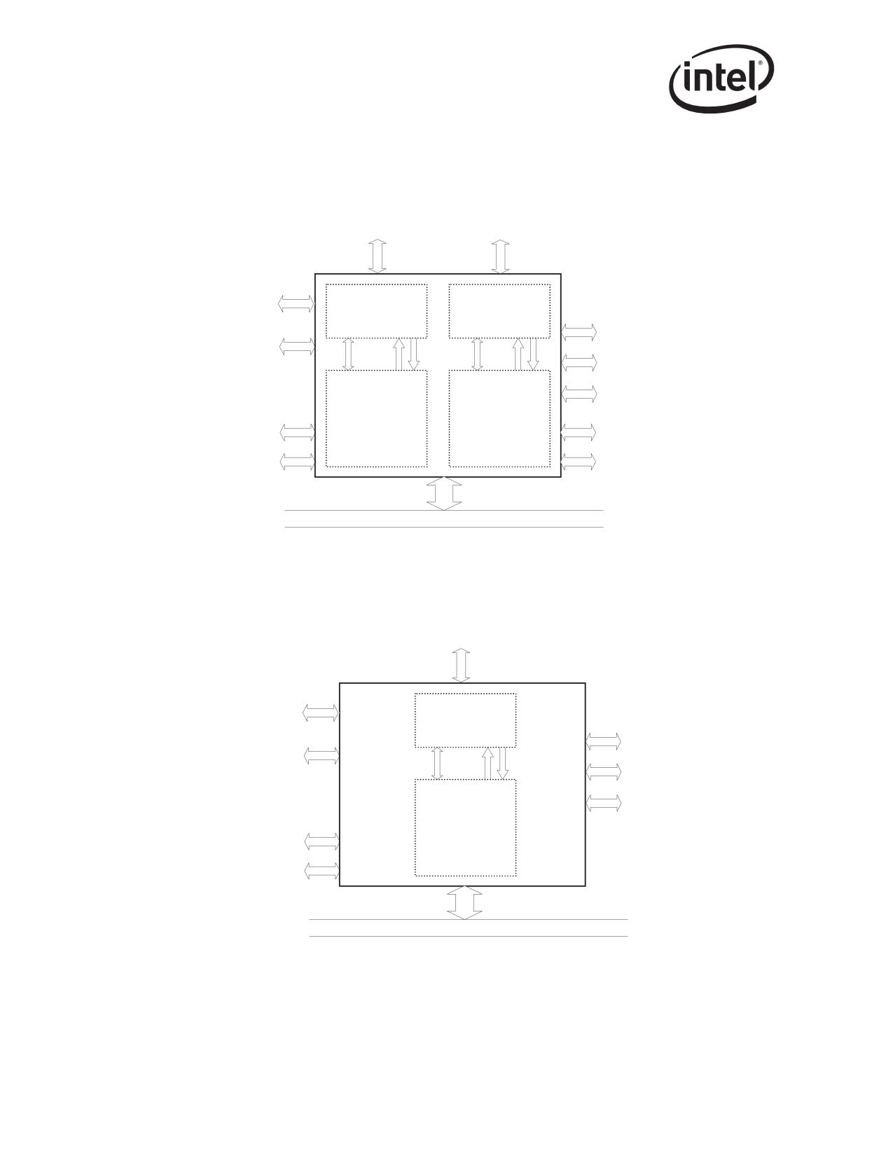
Figure 2-1 shows the external interfaces to the 82546GB/EB.
MDI
MDI
Interface A
Interface B
1000Base-T PHY Interfaces
Design for
10/100/1000
10/100/1000
Test Interface
PHY
PHY
SMBus
External
Interface
GMII/
GMII/
TBI Interface
MDIO
MDIO
EEPROM
MII
MII
Interface
Device
Device
Flash Interface
Function 0
Function 1
MAC/Controller
MAC/Controller
LEDs
LEDs
(LAN A)
(LAN B)
Software
Software
Defined Pins
Defined Pins
PCI (64-bit, 33/66 MHz)/PCI-X (133 MHz)
Figure 2-1. 82546GB/EB External Interface
Figure 2-2 shows the external interfaces to the 82545GM/EM, 82544GC/EI, 82540EP/EM, and
82541xx.
MDI
Interface
1000Base-T PHY Interface
Design for
10/100/1000
Test Interface
PHY
SMBus
Interface
External
TBI Interface
MDIO
GMII/
MII
EEPROM
(82545GM/EM only)
Interface
Flash Interface
Device
Function 0
LEDs
MAC/Controller
Software
Defined Pins
PCI (64-bit, 33/66 MHz)/PCI-X (133 MHz)
Note: 82540EP/EM and 82541xx do not support PCI-X; 82544GC/EI and 82541ER do not support SMBus interface
Figure 2-2. 82545GM/EM, 82544GC/EI, 82540EP/EM, and 82541xx External Interface
8
Architectural Overview
Figure 2-3 shows the external interfaces to the 82547GI/EI.
CSA Port
PCI Core
EEPROM
FLASH
Slave
DMA Function
Access
Descriptor Management
Logic
40KB
Packet
RAM
RX Filters
Control
TX/RX MAC
(Perfect,
Status
CSMA/CD
Multicast,
Logic
VLAN)
N
Statistics
8 bits
Management
8 bits
Interface
Trellis Viterbi
Side-stream
Encoder/Decoder
Scrambler/
Descrambler
PHY
4 bits
Control
4 bits
ECHO, NEXT,
4DPAM5
FEXT
Encoder
Cancellers
AGC, A/D
Pulse Shaper,
Timing
DAC, Filter
Recovery
Hybrid
Line Driver
Media Dependent Interface
Figure 2-3. 82547GI(EI) External Interface
9

Architectural Overview
2.3
Microarchitecture
Compared to its predecessors, the PCI/PCI-X Family of Gigabit Ethernet Controller’s MAC adds
improved receive-packet filtering to support SMBus-based manageability, as well as the ability to
transmit SMBus-based manageability packets. In addition, an ASF-compliant TCO controller is
integrated into the controller’s MAC for reduced-cost basic ASF manageability.
Note: The 82544GC/EI and 82541ER do not support SMBus-based manageability.
For the 82546GB/EB, this new functionality is packaged in an integrated dual-port combination.
The architecture includes two instances of both the MAC and PHY along with a single PCI/PCI-X
interface. As a result, each of the logical LAN devices appear as a distinct PCI/PCI-X bus device.
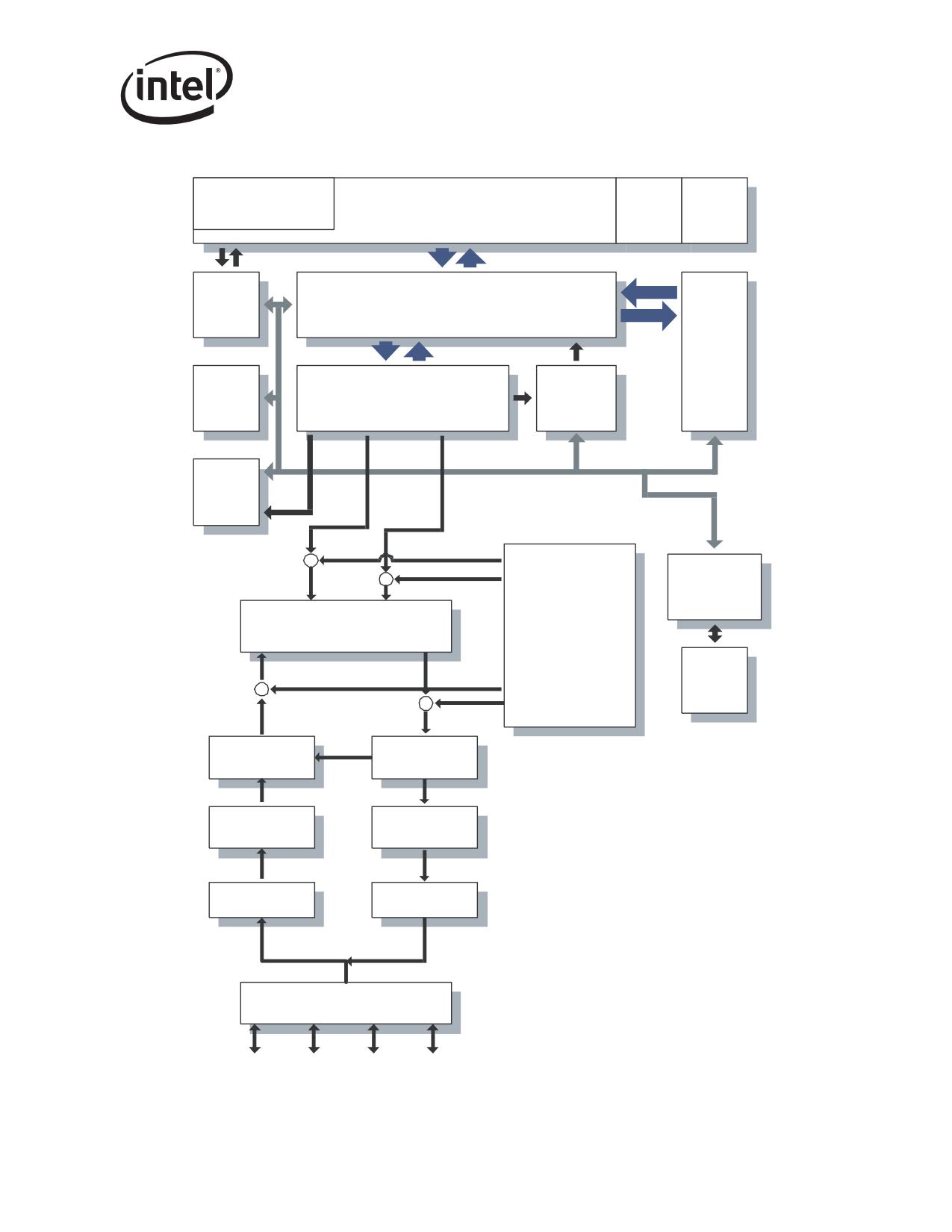
The following sections describe the hardware building blocks. Figure 2-4 shows the internal
microarchitecture.
2.3.1
PCI/PCI-X Core Interface
The PCI/PCI-X core provides a complete glueless interface to a 33/66 MHz, 32/64-bit PCI bus or a
33/66/133 MHz, 32/64 bit PCI-X bus. It is compliant with the PCI Bus Specification Rev 2.2 or 2.3
and the PCI-X Specification Rev. 1.0a. The Ethernet controllers provide 32 or 64 bits of addressing
and data, and the complete control interface to operate on a 32-bit or 64-bit PCI or PCI-X bus. In
systems with a dedicated bus for the Ethernet controller, this provides sufficient bandwidth to
support sustained 1000 Mb/s full-duplex transfer rates. Systems with a shared bus (especially the
32-bit wide interface) might not be able to maintain 1000 Mb/s, but can sustain multiple hundreds
of Mbps.
Host Arbiter
TX MAC
TX
(10/100/
Link I/F
Switch
DMA
1000 Mb)
GMII/
Engine
MII
PCI/
RX MAC
PCI Interface
PCI-X
(10/100/
Packet/
Core
Manageability
1000 Mb)
Filter
MDIO
Packet
ASF
MDIO
Buffer
Manageability
RMON
Statistics
SM Bus
EEPROM
Flash
Figure 2-4. Internal Architecture Block Diagram
10
Architectural Overview
When the Ethernet controller serves as a PCI target, it follows the PCI configuration specification,
which allows all accesses to it to be automatically mapped into free memory and I/O space at
initialization of the PCI system.
When processing transmit and receive frames, the Ethernet controller operates as master on the PCI
bus. As a master, transaction burst length on the PCI bus is determined by several factors, including
the PCI latency timer expiration, the type of bus transfer being made, the size of the data transfer,
and whether the data transfer is initiated by receive or transmit logic.
The PCI/PCI-X bus interfaces to the DMA engine.
2.3.2
82547GI/EI CSA Interface
CSA is derived from the Intel® Hub Architecture. The 82547EI Controller CSA port consists of 11
data and control signals, two strobes, a 66 MHz clock, and driver compensation resistor connec-
tions. The operating details of these signals and the packet data protocol that accompanies them are
proprietary. The CSA port has a theoretical bandwidth of 266 MB/s - approximately twice the
peak bandwidth of a 32-bit 33 MHz PCI bus.
The CSA port architecture is invisible to both system software and the operating system, allowing
conventional PCI-like configuration.
2.3.3
DMA Engine and Data FIFO
The DMA engine handles the receive and transmit data and descriptor transfers between the host
memory and the on-chip memory.
In the receive path, the DMA engine transfers the data stored in the receive data FIFO buffer to the
receive buffer in the host memory, specified by the address in the descriptor. It also fetches and
writes back updated receive descriptors to host memory.
In the transmit path, the DMA engine transfers data stored in the host memory buffers to the
transmit data FIFO buffer. It also fetches and writes back updated transmit descriptors.
The Ethernet controller data FIFO block consists of a 64 KB (40 KB for the 82547GI/EI) on-chip
buffer for receive and transmit operation. The receive and transmit FIFO size can be allocated
based on the system requirements. The FIFO provides a temporary buffer storage area for frames
as they are received or transmitted by the Ethernet controller.
The DMA engine and the large data FIFOs are optimized to maximize the PCI bus efficiency and
reduce processor utilization by:
• Mitigating instantaneous receive bandwidth demands and eliminating transmit underruns by
buffering the entire out-going packet prior to transmission
• Queuing transmit frames within the transmit FIFO, allowing back-to-back transmission with
the minimum interframe spacing
• Allowing the Ethernet controller to withstand long PCI bus latencies without losing incoming
data or corrupting outgoing data
• Allowing the transmit start threshold to be tuned by the transmit FIFO threshold. This
adjustment to system performance is based on the available PCI bandwidth, wire speed, and
latency considerations
11
Architectural Overview
• Offloading the receiving and transmitting IP and TCP/UDP checksums
• Directly retransmitting from the transmit FIFO any transmissions resulting in errors (collision
detection, data underrun), thus eliminating the need to re-access this data from host memory
2.3.4
10/100/1000 Mb/s Receive and Transmit MAC Blocks
The controller’s CSMA/CD unit handles all the IEEE 802.3 receive and transmit MAC functions
while interfacing between the DMA and TBI/internal SerDes/MII/GMII interface block. The
CSMA/CD unit supports IEEE 802.3 for 10 Mb/s, IEEE 802.3u for 100 Mb/s and IEEE 802.3z and
IEEE 802.3ab for 1000 Mb/s.
The Ethernet controller supports half-duplex 10/100 Mb/s MII or 1000 Mb/s GMII mode and all
aspects of the above specifications in full-duplex operation. In half-duplex mode, the Ethernet
controller supports operation as specified in IEEE 802.3z specification. In the receive path, the
Ethernet controller supports carrier extended packets and packets generated during packet bursting
operation. The 82554GC/EI, in the transmit path, also supports carrier extended packets and can
be configured to transmit in packet burst mode.
The Ethernet controller offers various filtering capabilities that provide better performance and
lower processor utilization as follows:
• Provides up to 16 addresses for exact match unicast/multicast address filtering.
• Provides multicast address filtering based on 4096 bit vectors. Promiscuous unicast and
promiscuous multicast filtering are supported as well.
• The Ethernet controller strips IEEE 802.1q VLAN tag and filter packets based on their VLAN
ID. Up to 4096 VLAN tags are supported1.
In the transmit path, the Ethernet controller supports insertion of VLAN tag information, on a
packet-by-packet basis.
The Ethernet controller implements the flow control function as defined in IEEE 802.3x, as well as
specific operation of asymmetrical flow control as defined by IEEE 802.3z. The Ethernet controller
also provides external pins for controlling the flow control function through external logic.
2.3.5
MII/GMII/TBI/Internal SerDes Interface Block
The Ethernet controller provides the following serial interfaces:
• A GMII/MII interface to the internal PHY.
• Internal SerDes interface2 (82546GB/EB and 82545GM/EM)/Ten Bit Interface (TBI)2 for the
82544GC/EI: The Ethernet controller implements the 802.3z PCS function, the Auto-
Negotiation function and 10-bit data path interface (TBI) for both receive and transmit
operations. It is used for 1000BASE-SX, -LX, and -CX configurations, operating only at 1000
Mb/s full-duplex. The on-chip PCS circuitry is only used when the link interface is configured
for TBI mode and it is bypassed in internal PHY modes.
1.
Not applicable to the 82541ER.
2.
Not applicable to the 82544GC/EI, 82540EP/EM, 82541xx, and 82547GI/EI.
12
Architectural Overview
Note: Refer to the Extended Device Control Register (bits 23:22) for mode selection (see Section 13.4.6).
The link can be configured by several methods. Software can force the link setting to Auto-
Negotiation by setting either the MAC in TBI mode (internal SerDes for the 82546GB/EB and
82545GM/EM), or the PHY in internal PHY mode.
The speed of the link in internal PHY mode can be determined by several methods:
• Auto speed detection based on the receive clock signal generated by the PHY.
• Detection of the PHY link speed indication.
• Software forcing the configuration of link speed.
2.3.6
10/100/1000 Ethernet Transceiver (PHY)
The Ethernet controller provides a full high-performance, integrated transceiver for 10/100/
1000 Mb/s data communication. The physical layer (PHY) blocks are 802.3 compliant and capable
of operating in half-duplex or full-duplex modes.
Highlights of the PHY blocks are as follows:
• Data stream serializers and encoders. Encoding techniques include Manchester, 4B/5B and
4D/PAM5. These blocks also perform data scrambling for 100/1000 Mb/s transmission as a
technique to minimize radiated Electromagnetic Interference (EMI).
• A multi-mode transmit digital to analog converter, which produces filtered waveforms
appropriate for the 10BASE-T, 100BASE-TX or 1000BASE-T Ethernet standards.
• Receiver Analog-to-Digital Converter (ADC). The ADC uses a 125 MHz sampling rate.
• Receiver decoders. These blocks perform the inverse operations of serializers, encoders and
scramblers.
• Active hybrid and echo canceller blocks. The active hybrid and echo canceller blocks reduce
the echo effect of transmitting and receiving simultaneously on the same analog pairs.
• NEXT canceller. This unit removes high frequency Near End Crosstalk induced among
adjacent signal pairs.
• Additional wave shaping and slew rate control circuitry to reduce EMI.
Because the Ethernet controller is IEEE-compliant, the PHY blocks communicate with the MAC
blocks through an internal GMII/MII bus operating at clock speeds of 2.5 MHz up to 125 MHz.
The Ethernet controller also uses an IEEE-compliant internal Management Data interface to
communicate control and status information to the PHY.
2.3.7
EEPROM Interface
The PCI/PCI-X Family of Gigabit Ethernet Controllers provide a four-wire direct interface to a
serial EEPROM device such as the 93C46 or compatible for storing product configuration
information. Several words of the data stored in the EEPROM are automatically accessed by the
Ethernet controller, after reset, to provide pre-boot configuration data to the Ethernet controller
before it is accessible by the host software. The remainder of the stored information is accessed by
various software modules to report product configuration, serial number and other parameters.
13
Architectural Overview
2.3.8
FLASH Memory Interface
The Ethernet controller provides an external parallel interface to a FLASH device. Accesses to the
FLASH are controlled by the Ethernet controller and are accessible to software as normal PCI
reads or writes to the FLASH memory mapping area. The Ethernet controller supports FLASH
devices with up to 512 KB of memory.
Note: The 82540EP/EM provides an external interface to a serial FLASH or Boot EEPROM device. See
Appendix B for more information.
2.4
DMA Addressing
In appropriate systems, all addresses mastered by the Ethernet controller are 64 bits in order to
support systems that have larger than 32-bit physical addressing. Providing 64-bit addresses
eliminates the need for special segment registers.
Note: The PCI 2.2 or 2.3 Specification requires that any 64-bit address whose upper 32 bits are all 0b
appear as a 32-bit address cycle. The Ethernet controller complies with the PCI 2.2 or 2.3
Specification.
PCI is little-endian; however, not all processors in systems using PCI treat memory as little-endian.
Network data is fundamentally a byte stream. As a result, it is important that the processor and
Ethernet controller agree about the representation of memory data. The default is little-endian
mode.
Descriptor accesses are not byte swapped.
The following example illustrates data-byte ordering for little endian. Bytes for a receive packet
arrive in the order shown from left to right.
01 02 03 04 05 06 07 08 09 0a 0b 0c 0d 0e 0f 10 11 12 13 14 15 16 17 18 19 1a 1b 1c 1d 1e
Example 2-1. Byte Ordering
There are no alignment restrictions on packet-buffer addresses. The byte address for the major
words is shown on the left. The byte numbers and bit numbers for the PCI bus are shown across the
top.
Table 2-1. Little Endian Data Ordering
63
0
7
6
5
4
3
2
1
0
Byte
0
08
07
06
05
04
03
02
01
Address
8
10
0f
0e
0d
0c
0b
0a
09
10
18
17
16
15
14
13
12
11
18
20
1f
1e
1d
1c
1b
1a
19
14
Architectural Overview
2.5
Ethernet Addressing
Several registers store Ethernet addresses in the Ethernet controller. Two 32-bit registers make up
the address: one is called “high”, and the other is called “low”. For example, the Receive Address
Register is comprised of Receive Address High (RAH) and Receive Address Low (RAL). The least
significant bit of the least significant byte of the address stored in the register (for example, bit 0 of
RAL) is the multicast bit. The LS byte is the first byte to appear on the wire. This notation applies
to all address registers, including the flow control registers.
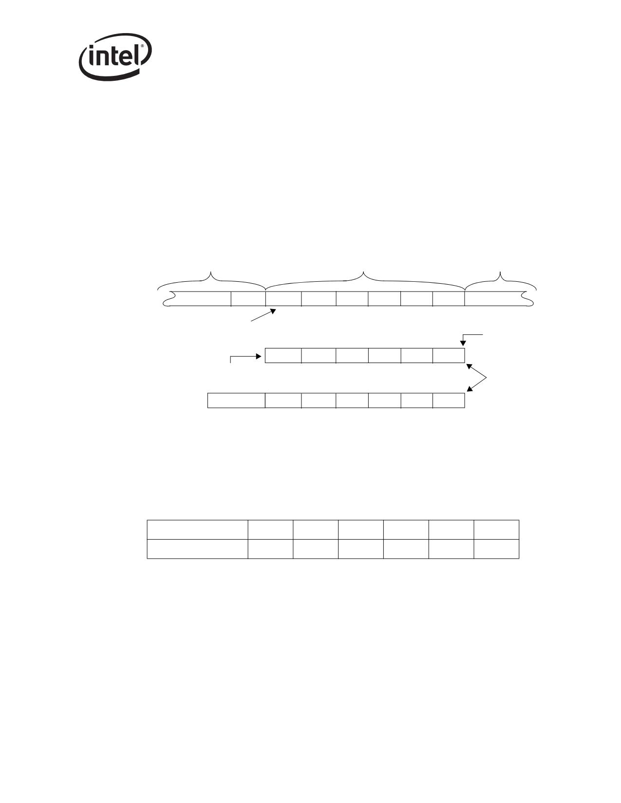
Figure 2-5 shows the bit/byte addressing order comparison between what is on the wire and the
values in the unique receive address registers.
Preamble & SFD
Destination Address
Source Address
...55
D5
00
AA
00
11
22
33
...XXX
Bit 0 of this byte is first on the wire
dest_addr[0]
33
22
1
1
00
AA
00
Destination address stored
internally as shown here
Multicast bit
33
22
1
1
00
AA
00
Figure 2-5. Example of Address Byte Ordering
The address byte order numbering shown in Figure 2-5 maps to Table 2-2. Byte #1 is first on the
wire.
Table 2-2. Intel® Architecture Byte Ordering
IA Byte #
1 (LSB)
2
3
4
5
6 (MSB)
Byte Value (Hex)
00
AA
00
11
22
33
Note: The notation in this manual follows the convention shown in Table 2-2. For example, the address in
Table 2-2 indicates 00_AA_00_11_22_33h, where the first byte (00h_) is the first byte on the wire,
with bit 0 of that byte transmitted first.
15
Architectural Overview
2.6
Interrupts
The Ethernet controller provides a complete set of interrupts that allow for efficient software
management. The interrupt structure is designed to accomplish the following:
• Make accesses “thread-safe” by using ‘set’ and ‘clear-on-read’ rather than ‘read-modify-write’
operations.
• Minimize the number of interrupts needed relative to work accomplished.
• Minimize the processing overhead associated with each interrupt.
Intel accomplished the first goal by an interrupt logic consisting of four interrupt registers. More
detail about these registers is given in sections 13.4.17 through 13.4.21.
• Interrupt Cause ‘Set’ and ‘Read’ Registers
The Read register records the cause of the interrupt. All bits set at the time of the read are auto-
cleared. The cause bit is set for each bit written as a 1b in the Set register. If there is a race
between hardware setting a cause and software clearing an interrupt, the bit remains set. No
race condition exists on writing the Set register. A ‘set’ provides for software posting of an
interrupt. A ‘read’ is auto-cleared to avoid expensive write operations. Most systems have
write buffering, which minimizes overhead, but typically requires a read operation to
guarantee that the write operation has been flushed from the posted buffers. Without auto-
clear, the cost of clearing an interrupt can be as high as two reads and one write.
• Interrupt Mask ‘Set’ (Read) and ‘Clear’ Registers
Interrupts appear on PCI only if the interrupt cause bit is a 1b, and the corresponding interrupt
mask bit is a 1b. Software can block assertion of the interrupt wire by clearing the bit in the
mask register. The cause bit stores the interrupt event regardless of the state of the mask bit.
The Clear and Set operations make this register more “thread-safe” by avoiding a ‘read-
modify-write’ operation on the mask register. The mask bit is set to a 1b for each bit written in
the Set register, and cleared for each bit written in the Clear register. Reading the Set register
returns the current value.
Intel accomplished the second goal (minimizing interrupts) by three actions:
• Reducing the frequency of all interrupts (see Section 13.4.17). Not applicable to the
82544GC/EI.
• Accepting multiple receive packets before signaling an interrupt (see Section 3.2.3)
• Eliminating (or at least reducing) the need for interrupts on transmit (see Section 3.2.7)
The third goal is accomplished by having one interrupt register consolidate all interrupt
information. This eliminates the need for multiple accesses.
Note that the Ethernet controller also supports Message Signaled Interrupts as defined in the PCI
2.2, 2.3, and PCI-X specifications. See Section 4.1.3.1 for details.
16
Architectural Overview
2.7
Hardware Acceleration Capability
The Ethernet controller provides the ability to offload IP, TCP, and UDP checksum for transmit.
The functionality provided by these features can significantly reduce processor utilization by
shifting the burden of the functions from the driver to the hardware.
The checksum offloading feature is briefly outlined in the following sections. More detail about all
of the hardware acceleration capabilities is provided in Section 3.2.9.
2.7.1
Checksum Offloading
The Ethernet controller provides the ability to offload the IP, TCP, and UDP checksum require-
ments from the software device driver. For common frame types, the hardware automatically
calculates, inserts, and checks the appropriate checksum values normally handled by software.
For transmits, every Ethernet packet might have two checksums calculated and inserted by the
Ethernet controller. Typically, these would be the IP checksum, and either the TCP or UDP
checksum. The software device driver specifies which portions of the packet are included in the
checksum calculations, and where the calculated values are inserted via descriptors (refer to
Section 3.3.5 for details).
For receives, the hardware recognizes the packet type and performs the checksum calculations and
error checking automatically. Checksum and error information is provided to software through the
receive descriptors (refer to Section 3.2.9 for details).
2.7.2
TCP Segmentation
The Ethernet controller implements a TCP segmentation capability for transmits that allows the
software device driver to offload packet segmentation and encapsulation to the hardware. The
software device driver can send the Ethernet controller the entire IP, TCP or UDP message sent
down by the Network Operating System (NOS) for transmission. The Ethernet controller segments
the packet into legal Ethernet frames and transmit them on the wire. By handling the segmentation
tasks, the hardware alleviates the software from handling some of the framing responsibilities. This
reduces the overhead on the CPU for the transmission process thus reducing overall CPU
utilization. See Section 3.5 for details.
2.8
Buffer and Descriptor Structure
Software allocates the transmit and receive buffers, and also forms the descriptors that contain
pointers to, and the status of, those buffers. A conceptual ownership boundary exists between the
driver software and the hardware of the buffers and descriptors. The software gives the hardware
ownership of a queue of buffers for receives. These receive buffers store data that the software then
owns once a valid packet arrives.
For transmits, the software maintains a queue of buffers. The driver software owns a buffer until it
is ready to transmit. The software then commits the buffer to the hardware; the hardware then owns
the buffer until the data is loaded or transmitted in the transmit FIFO.
17
Architectural Overview
Descriptors store the following information about the buffers:
• The physical address
• The length
• Status and command information about the referenced buffer
Descriptors contain an end-of-packet field that indicates the last buffer for a packet. Descriptors
also contain packet-specific information indicating the type of packet, and specific operations to
perform in the context of transmitting a packet, such as those for VLAN or checksum offload.
Section 3 provides detailed information about descriptor structure and operation in the context of
packet transmission and reception.
18
Receive and Transmit Description
3
3.1
Introduction
This section describes the packet reception, packet transmission, transmit descriptor ring structure,
TCP segmentation, and transmit checksum offloading for the PCI/PCI-X Family of Gigabit
Ethernet Controllers.
Note: The 82544GC/EI does not support IPv6.
3.2
Packet Reception
In the general case, packet reception consists of recognizing the presence of a packet on the wire,
performing address filtering, storing the packet in the receive data FIFO, transferring the data to a
receive buffer in host memory, and updating the state of a receive descriptor.
3.2.1
Packet Address Filtering
Hardware stores incoming packets in host memory subject to the following filter modes. If there is
insufficient space in the receive FIFO, hardware drops them and indicates the missed packet in the
appropriate statistics registers.
The following filter modes are supported:
• Exact Unicast/Multicast - The destination address must exactly match one of 16 stored
addresses. These addresses can be unicast or multicast.
• Promiscuous Unicast - Receive all unicasts.
• Multicast - The upper bits of the incoming packet’s destination address index a bit vector
that indicates whether to accept the packet; if the bit in the vector is one, accept the packet,
otherwise, reject it. The controller provides a 4096 bit vector. Software provides four choices
of which bits are used for indexing. These are [47:36], [46:35], [45:34], or [43:32] of the
internally stored representation of the destination address.
• Promiscuous Multicast - Receive all multicast packets.
• VLAN - Receive all VLAN1 packets that are for this station and have the appropriate bit set
in the VLAN filter table. A detailed discussion and explanation of VLAN packet filtering is
contained in Section 9.3.
Normally, only good packets are received. These are defined as those packets with no CRC error,
symbol error, sequence error, length error, alignment error, or where carrier extension or receive
errors are detected. However, if the store-bad-packet bit is set in the Device Control register
(RCTL.SBP), then bad packets that pass the filter function are stored in host memory. Packet errors
are indicated by error bits in the receive descriptor (RDESC.ERRORS). It is possible to receive all
packets, regardless of whether they are bad, by setting the promiscuous enables (RCTL.UPE/MPE)
and the store-bad-packet bit (RCTL.SBP).
1. Not applicable to the 82541ER.
19
Receive and Transmit Description
If manageability is enabled and if RCMCP is enabled then ARP request packets can be directed
over the SMBus or processed internally by the ASF controller rather than delivered to host memory
(not applicable to the 82544GC/EI or 82541ER.
3.2.2
Receive Data Storage
Memory buffers pointed to by descriptors store packet data. Hardware supports seven receive
buffer sizes:
• 256 B
• 4096 B
• 512 B
• 8192 B
• 1024 B
• 16384 B
• 2048 B
Buffer size is selected by bit settings in the Receive Control register (RCTL.BSIZE &
RCTL.BSEX). See Section 13.4.22 for details.
The Ethernet controller places no alignment restrictions on packet buffer addresses. This is
desirable in situations where the receive buffer was allocated by higher layers in the networking
software stack, as these higher layers may have no knowledge of a specific Ethernet controller’s
buffer alignment requirements.
Although alignment is completely unrestricted, it is highly recommended that software allocate
receive buffers on at least cache-line boundaries whenever possible.
3.2.3
Receive Descriptor Format
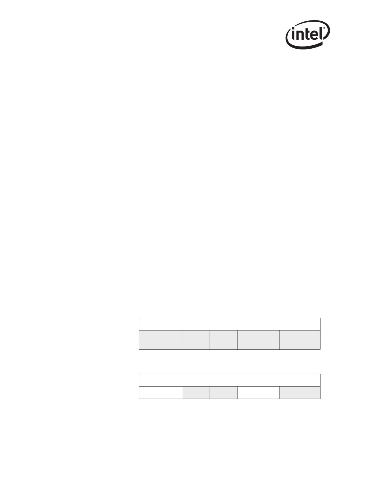
A receive descriptor is a data structure that contains the receive data buffer address and fields for
hardware to store packet information. Table 3-1 lists where the shaded areas indicate fields that are
modified by hardware upon packet reception.
Table 3-1. Receive Descriptor (RDESC) Layout
63
48 47
40 39
32 31
16 15
0
0
Buffer Address [63:0]
Packet Checksum
8
Special
Errors
Status
Length
(See Note)
82544GC/EI only
63
48 47
40 39
32 31
16 15
0
0
Buffer Address [63:0]
8
Reserved
Errors
Status
Reserved
Length
Note: The checksum indicated here is the unadjusted “16 bit ones complement” of the packet. A software
assist may be required to back out appropriate information prior to sending it to upper software
20

Receive and Transmit Description
layers. The packet checksum is always reported in the first descriptor (even in the case of multi-
descriptor packets).
Upon receipt of a packet for Ethernet controllers, hardware stores the packet data into the indicated
buffer and writes the length, Packet Checksum, status, errors, and status fields. Length covers the
data written to a receive buffer including CRC bytes (if any). Software must read multiple
descriptors to determine the complete length for packets that span multiple receive buffers.
For standard 802.3 packets (non-VLAN) the Packet Checksum is by default computed over the
entire packet from the first byte of the DA through the last byte of the CRC, including the Ethernet
and IP headers. Software may modify the starting offset for the packet checksum calculation by
means of the Receive Control Register. This register is described in Section 13.4.22. To verify the
TCP checksum using the Packet Checksum, software must adjust the Packet Checksum value to
back out the bytes that are not part of the true TCP Checksum.
3.2.3.1
Receive Descriptor Status Field
Status information indicates whether the descriptor has been used and whether the referenced
buffer is the last one for the packet. Refer to Table 3-2 for the layout of the status field. Error status
information is shown in Table 3-3.
For multi-descriptor packets, packet status is provided in the final descriptor of the packet (EOP
set). If EOP is not set for a descriptor, only the Address, Length, and DD bits are valid.
Table 3-2. Receive Status (RDESC.STATUS) Layout
7
6
5
4
3
2
1
0
PIF
IPCS
TCPCS
RSV
VP
IXSM
EOP
DD
Receive
Descriptor Status
Description
Bits
Passed in-exact filter
Hardware supplies the PIF field to expedite software processing of packets.
Software must examine any packet with PIF set to determine whether to accept
PIF (bit 7)
the packet. If PIF is clear, then the packet is known to be for this station, so
software need not look at the packet contents. Packets passing only the
Multicast Vector has PIF set.
IP Checksum Calculated on Packet
When Ignore Checksum Indication is deasserted (IXSM = 0b), IPCS bit indicates
whether the hardware performed the IP checksum on the received packet.
0b = Do not perform IP checksum
IPCS (bit 6)
1b = Perform IP checksum
Pass/Fail information regarding the checksum is indicated in the error bit (IPE) of
the descriptor receive errors (RDESC.ERRORS)
IPv6 packets do not have the IPCS bit set.
Reads as 0b.
21

Receive and Transmit Description
Receive
Descriptor Status
Description
Bits
TCP Checksum Calculated on Packet
When Ignore Checksum Indication is deasserted (IXSM = 0b), TCPCS bit
indicates whether the hardware performed the TCP/UDP checksum on the
received packet.
TCPCS (bit 5)
0b = Do not perform TCP/UDP checksum; 1b = Perform TCP/UDP checksum
Pass/Fail information regarding the checksum is indicated in the error bit (TCPE)
of the descriptor receive errors (RDESC.ERRORS).
IPv6 packets may have this bit set if the TCP/UDP packet was recognized.
Reads as 0b.
Reserved
RSV (bit 4)
Reads as 0b.
Packet is 802.1Q (matched VET)
Indicates whether the incoming packet’s type matches VET (i.e., if the packet is
VP (bit 3)
a VLAN (802.1q) type). It is set if the packet type matches VET and CTRL.VME
is set. For a further description of 802.1q VLANs, see Chapter 9.
Reads as 0b.
Ignore Checksum Indication
When IXSM = 1b, the checksum indication results (IPCS, TCPCS bits) should be
ignored.
When IXSM = 0b the IPCS and TCPCS bits indicate whether the hardware
IXSM (bit 2)
performed the IP or TCP/UDP checksum(s) on the received packet. Pass/Fail
information regarding the checksum is indicated in the status bits as described
below for IPE and TCPE.
Reads as 1b.
End of Packet
EOP (bit 1)
EOP indicates whether this is the last descriptor for an incoming packet.
Descriptor Done
DD (bit 0)
Indicates whether hardware is done with the descriptor. When set along with
EOP, the received packet is complete in main memory.
Note:
See Table 3-5 for a description of supported packet types for receive checksum offloading.
Unsupported packet types either have the IXSM bit set, or they don’t have the TCPCS bit set.
3.2.3.2
Receive Descriptor Errors Field
Most error information appears only when the Store Bad Packets bit (RCTL.SBP) is set and a bad
packet is received. Refer to Table 3-3 for a definition of the possible errors and their bit positions.
The error bits are valid only when the EOP and DD bits are set in the descriptor status field
(RDESC.STATUS)
22

Receive and Transmit Description
Table 3-3. Receive Errors (RDESC.ERRORS) Layout
7
6
5
4
3
2
1
0
RSV
SEQ
SE
RXE
IPE
TCPE
RSV
CE
CXEa
RSVb
RSVb
a.
82544GC/EI only.
b.
82541xx, 82547GI/EI, and 82540EP/EM only.
Receive
Descriptor Error
Description
bits
RX Data Error
Indicates that a data error occurred during the packet reception. A data error in TBIa
mode (82544GC/EI)/internal SerDes (82546GB/EB and 82545GM/EM) refers to the
RXE (bit 7)
reception of a /V/ code (see Section 8.2.1.3). In GMII or MII mode, the assertion of
I_RX_ER during data reception indicates a data error. This bit is valid only when the
EOP and DD bits are set; it is not set in descriptors unless RCTL.SBP (Store Bad
Packets) control bit is set.
IP Checksum Error
When set, indicates that IP checksum error is detected in the received packet. Valid
only when the IP checksum is performed on the receive packet as indicated via the
IPE (bit 6)
IPCS bit in the RDESC.STATUS field.
If receive IP checksum offloading is disabled (RXCSUM.IPOFL), the IPE bit is set to
0b. It has no effect on the packet filtering mechanism.
Reads as 0b.
TCP/UDP Checksum Error
When set, indicates that TCP/UDP checksum error is detected in the received
packet.
Valid only when the TCP/UDP checksum is performed on the receive packet as
TCPE (bit 5)
indicated via TCPCS bit in RDESC.STATUS field.
If receive TCP/UDP checksum offloading is disabled (RXCSUM.TUOFL), the TCPE
bit is set to 0b.
It has no effect on the packet filtering mechanism.
Reads as 0b.
Carrier Extension Error
When set, indicates a packet was received in which the carrier extension error was
CXE
signaled across the GMII interface. A carrier extension error is signaled by the PHY
RSV (bit 4)
by the encoding of 1Fh on the receive data inputs while I_RX_ER is asserted.
Valid only while working in 1000 Mb/s half-duplex mode of operation.
This bit is reserved for all Ethernet controllers except the 82544GC/EI.
Reserved
RSV (Bit 3)
Reads as 0b.
23
Receive and Transmit Description
Receive
Descriptor Error
Description
bits
Sequence Error
When set, indicates a received packet with a bad delimiter sequence (in TBI mode/
internal SerDes). In other 802.3 implementations, this would be classified as a
SEQ (bit 2)
framing error.
A valid delimiter sequence consists of:
idle start-of-frame (SOF) data, pad (optional) end-of-frame (EOF) fill
(optional) idle.
Symbol Error
SE (bit 1)
When set, indicates a packet received with bad symbol. Applicable only in TBI mode/
internal SerDes.
CRC Error or Alignment Error
CE (bit 0)
CRC errors and alignment errors are both indicated via the CE bit. Software may
distinguish between these errors by monitoring the respective statistics registers.
a. Not applicable to the 82540EP/EM, 82541xx, or 82547GI/EI.
3.2.3.3
Receive Descriptor Special Field
Hardware stores additional information in the receive descriptor for 802.1q packets. If the packet
type is 802.1q, determined when a packet type field matches the VLAN1 Ethernet Register (VET)
and RCTL.VME = 1b, then the special field records the VLAN information and the four byte
VLAN information is stripped from the packet data storage. The Ethernet controller stores the Tag
Control Information (TCI) of the 802.1q tag in the Special field. Otherwise, the special field
contains 0000h.
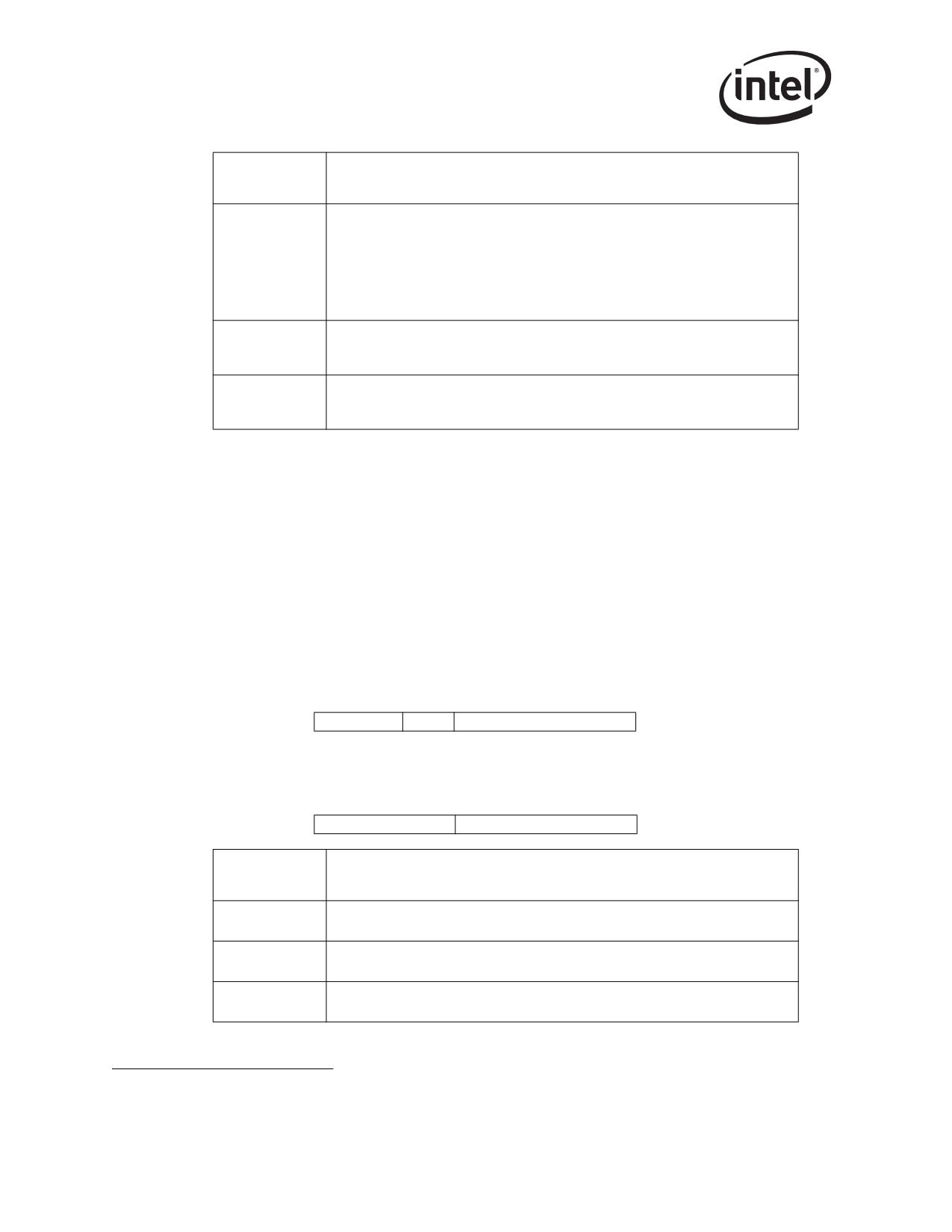
Table 3-4. Special Descriptor Field Layout
802.1q Packets
15
13
12
11
0
PRI
CFI
VLAN
All Other Packets
15
8 7
0
00
00
Receive
Descriptor
Description
Special Field
VLAN Identifier
VLAN
12 bits that records the packet VLAN ID number
Canonical Form Indicator
CFI
1 bit that records the packet’s CFI VLAN field
User Priority
PRI
3 bits that records the packet’s user priority field.
1.
Not applicable to the 82541ER.
24
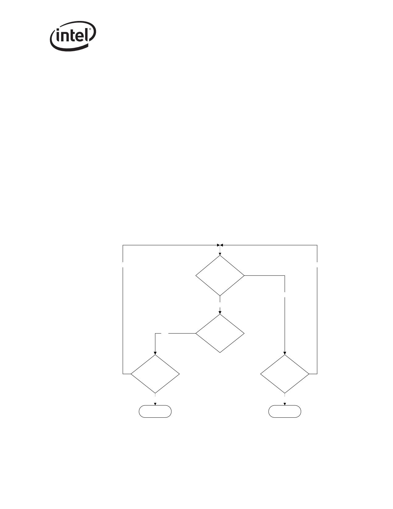
Receive and Transmit Description
3.2.4
Receive Descriptor Fetching
The descriptor fetching strategy is designed to support large bursts across the PCI bus. This is made
possible by using 64 on-chip receive descriptors and an optimized fetching algorithm. The fetching
algorithm attempts to make the best use of PCI bandwidth by fetching a cache line (or more)
descriptors with each burst. The following paragraphs briefly describe the descriptor fetch
algorithm and the software control provided.
When the on-chip buffer is empty, a fetch happens as soon as any descriptors are made available
(software writes to the tail pointer). When the on-chip buffer is nearly empty
(RXDCTL.PTHRESH), a prefetch is performed whenever enough valid descriptors
(RXDCTL.HTHRESH) are available in host memory and no other PCI activity of greater priority
is pending (descriptor fetches and write-backs or packet data transfers).
When the number of descriptors in host memory is greater than the available on-chip descriptor
storage, the chip may elect to perform a fetch which is not a multiple of cache line size. The
hardware performs this non-aligned fetch if doing so results in the next descriptor fetch being
aligned on a cache line boundary. This mechanism provides the highest efficiency in cases where
fetches fall behind software.
Note: The Ethernet controller never fetches descriptors beyond the descriptor TAIL pointer.
No
No
On-chip
descriptor cache
is empty
Yes
No
On-chip
Yes
descriptor cache <
RDXCTL.PTHRESH
Valid descriptors
Descriptors
in host memory >
are available in
RXDCTL.HTHRESH
host memory
Yes
Yes
Pre-fetch (based
Fetch
on PCI priority)
Figure 3-1. Receive Descriptor Fetching Algorithm
25
Receive and Transmit Description
3.2.5
Receive Descriptor Write-Back
Processors have cache line sizes that are larger than the receive descriptor size (16 bytes).
Consequently, writing back descriptor information for each received packet would cause expensive
partial cache line updates. Two mechanisms minimize the occurrence of partial line write backs:
• Receive descriptor packing
• Null descriptor padding
The following sections explain these mechanisms.
3.2.5.1
Receive Descriptor Packing
To maximize memory efficiency, receive descriptors are “packed” together and written as a cache
line whenever possible. Descriptors accumulate and are written out in one of three conditions:
• RXDCTL.WTHRESH descriptors have been used (the specified max threshold of unwritten
used descriptors has been reached)
• The receive timer expires (RADV or RDTR)
• Explicit software flush (RDTR.FPD)
For the first condition, if the number of descriptors specified by RXDCTL.WTHRESH are used,
they are written back, regardless of cacheline alignment. It is therefore recommended that
WTHRESH be a multiple of cacheline sizes.
In the second condition, a timer (RDTR or RADV) expiration causes all used descriptors to be
written back prior to initiating an interrupt.
In the second condition for the 82544GC/EI, a timer (RDTR) is included to force timely write-
back of descriptors. The first packet after timer initialization starts the timer. Timer expiration
flushes any accumulated descriptors and sets an interrupt event (receiver timer interrupt). In
general, the arrival rate is sufficiently fast enough that packing is the common case under load.
For the final condition, software may explicitly flush accumulated descriptors by writing the timer
register with the high order bit set.
3.2.5.2
Null Descriptor Padding
Hardware stores no data in descriptors with a null data address. Software can make use of this
property to cause the first condition under receive descriptor packing to occur early. Hardware
writes back null descriptors with the DD bit set in the status byte and all other bits unchanged.
3.2.6
Receive Descriptor Queue Structure
Figure 3-2 shows the structure of the receive descriptor ring. Hardware maintains a circular ring of
descriptors and writes back used descriptors just prior to advancing the head pointer. Head and tail
pointers wrap back to base when “size” descriptors have been processed.
Software adds receive descriptors by writing the tail pointer with the index of the entry beyond the
last valid descriptor. As packets arrive, they are stored in memory and the head pointer is
incremented by hardware. When the head pointer is equal to the tail pointer, the ring is empty.
Hardware stops storing packets in system memory until software advances the tail pointer, making
more receive buffers available.
26
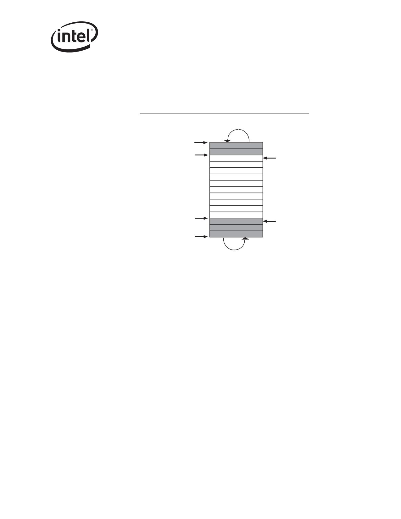
Receive and Transmit Description
The receive descriptor head and tail pointers reference 16-byte blocks of memory. Shaded boxes in
the figure represent descriptors that have stored incoming packets but have not yet been recognized
by software. Software can determine if a receive buffer is valid by reading descriptors in memory
rather than by I/O reads. Any descriptor with a non-zero status byte has been processed by the
hardware, and is ready to be handled by the software.
Circular Buffer Queues
Base
Head
Owned By
Receive
Hardware
Queue
Tail
Base + Size
Figure 3-2. Receive Descriptor Ring Structure
Note: The head pointer points to the next descriptor that is written back. At the completion of the
descriptor write-back operation, this pointer is incremented by the number of descriptors written
back. HARDWARE OWNS ALL DESCRIPTORS BETWEEN [HEAD AND TAIL]. Any
descriptor not in this range is owned by software.
The receive descriptor ring is described by the following registers:
• Receive Descriptor Base Address registers (RDBAL and RDBAH)
These registers indicate the start of the descriptor ring buffer. This 64-bit address is aligned on
a 16-byte boundary and is stored in two consecutive 32-bit registers. RDBAL contains the
lower 32-bits; RDBAH contains the upper 32 bits. Hardware ignores the lower 4 bits in
RDBAL.
• Receive Descriptor Length register (RDLEN)
This register determines the number of bytes allocated to the circular buffer. This value must
be a multiple of 128 (the maximum cache line size). Since each descriptor is 16 bytes in
length, the total number of receive descriptors is always a multiple of 8.
• Receive Descriptor Head register (RDH)
This register holds a value that is an offset from the base, and indicates the in-progress
descriptor. There can be up to 64K descriptors in the circular buffer. Hardware maintains a
shadow copy that includes those descriptors completed but not yet stored in memory.
27
Receive and Transmit Description
• Receive Descriptor Tail register (RDT)
This register holds a value that is an offset from the base, and identifies the location beyond the
last descriptor hardware can process. Note that tail should still point to an area in the descriptor
ring (somewhere between RDBA and RDBA + RDLEN). This is because tail points to the
location where software writes the first new descriptor.
If software statically allocates buffers, and uses memory read to check for completed descriptors, it
simply has to zero the status byte in the descriptor to make it ready for reuse by hardware. This is
not a hardware requirement (moving the hardware tail pointer is), but is necessary for performing
an in-memory scan.
3.2.7
Receive Interrupts
The Ethernet controller can generate four receive-related interrupts:
• Receiver Timer Interrupt (ICR.RXT0)
• Small Receive Packet Detect (ICR.SRPD)
• Receive Descriptor Minimum Threshold (ICR.RXDMT0)
• Receiver FIFO Overrun (ICR.RX0)
3.2.7.1
Receive Timer Interrupt
The Receive Timer Interrupt is used to signal most packet reception events (the Small Receive
Packet Detect interrupt is also used in some cases as described later in this section). In order to
minimize the interrupts per work accomplished, the Ethernet controller provides two timers to
control how often interrupts are generated.
3.2.7.1.1 Receive Interrupt Delay Timer / Packet Timer (RDTR)
The Packet Timer minimizes the number of interrupts generated when many packets are received
in a short period of time. The packet timer is started once a packet is received and transferred to
host memory (specifically, after the last packet data byte is written to memory) and is reinitialized
(to the value defined in RDTR) and started EACH TIME a new packet is received and transferred
to the host memory. When the Packet Timer expires (e.g. no new packets have been received and
transferred to host memory for the amount of time defined in RDTR) the Receive Timer Interrupt is
generated.
Setting the Packet Timer to 0b disables both the Packet Timer and the Absolute Timer (described
below) and causes the Receive Timer Interrupt to be generated whenever a new packet has been
stored in memory.
Writing to RDTR with its high order bit (FPD) set forces an explicit writeback of consumed
descriptors (potentially a partial cache lines amount of descriptors), causes an immediate expiration
of the Packet Timer and generates a Receive Timer Interrupt.
The Packet Timer is reinitialized (but not started) when the Receive Timer Interrupt is generated
due to an Absolute timer expiration or Small Receive Packet Detect Interrupt.
See section Section 13.4.30 for more details on the Packet Timer.
28
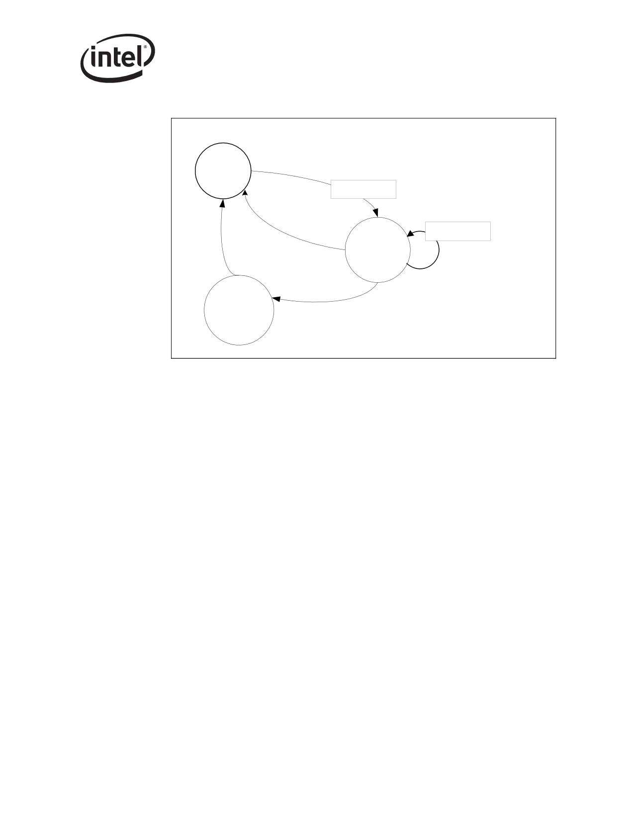
Receive and Transmit Description
Initial State
Packet received &
transferred to host
memory
Idle
Restart Count
Other receive
timer interrupt
Restart Count
Running
Packet received &
transferred to host
memory
Generate
Timer expires
Int
Figure 3-3. Packet Delay Timer Operation (State Diagram)
3.2.7.1.2 Receive Interrupt Absolute Delay Timer (RADV)
The Absolute Timer ensures that a receive interrupt is generated at some predefined interval after
the first packet is received. The absolute timer is started once a packet is received and transferred to
host memory (specifically, after the last packet data byte is written to memory) but is NOT
reinitialized / restarted each time a new packet is received. When the Absolute Timer expires (no
receive interrupt has been generated for the amount of time defined in RADV) the Receive Timer
Interrupt is generated.
Setting RADV to 0b or RDTR to 0b disables the Absolute Timer. To disable the Packet Timer only,
RDTR should be set to RADV + 1b.
The Absolute Timer is reinitialized (but not started) when the Receive Timer Interrupt is generated
due to a Packet Timer expiration or Small Receive Packet Detect Interrupt.
29
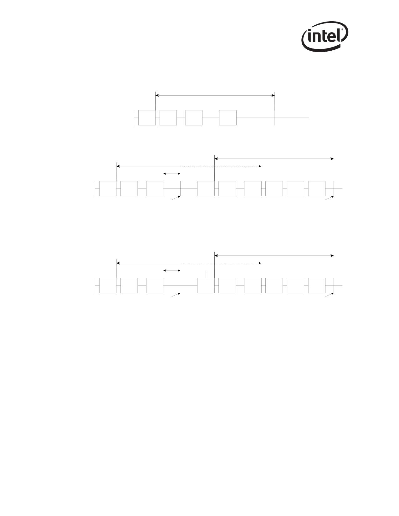
Receive and Transmit Description
The diagrams below show how the Packet Timer and Absolute Timer can be used together:
Case A: Using only an absolute timer
A bsolute Timer Value
Interrupt generated due to PKT #1
PKT #1
PKT #2
PKT #3
PKT #4
Case B: Using an absolute time in conjunction with the Packet timer
A bsolute Timer Value
A bsolute Timer Value
PKT #1
PKT #2
PKT #3
PKT #4
PKT #5
PKT #6
1) Packet timer expires
Interrupt generalted (due to PKT #4)
2) Interrupt generated
as absolute timer expires.
3) Absolute timer reset
Packet delay timer disabled untill
next packet is received and
transferred to host memory.
Case C: Packet timer expiring while a packet is transferred to host memory.
Illustrates that packet timer is re-started only after a packet is transferred to host memory.
A bsolute Timer Value
A bsolute Timer Value
PKT #1
PKT #2
PKT #3
PKT #4
PKT #5
PKT #6
1) Packet timer expires
Interrupt generalted (due to PKT #4)
2) Interrupt generated
as absolute timer expires.
3) Absolute timer reset
Packet delay timer disabled untill
next packet is received and
transferred to host memory.
3.2.7.2
Small Receive Packet Detect
A Small Receive Packet Detect interrupt (ICR.SRPD) is asserted when small-packet detection is
enabled (RSRPD is set with a non-zero value) and a packet of (size RSRPD.SIZE) has been
transferred into the host memory. When comparing the size the headers and CRC are included (if
CRC stripping is not enabled). CRC and VLAN headers are not included if they have been
stripped. A receive timer interrupt cause (ICR.RXT0) is also noted when the Small Packet Detect
interrupt occurs.
For the 82541xx and 82547GI/EI, receiving a small packet does not clear the absolute or packet
delay timers, so one packet might generate two interrupts, one due to small packet reception and
one due to timer expiration.
30
Receive and Transmit Description
3.2.7.3
Receive Descriptor Minimum Threshold (ICR.RXDMT)
The minimum descriptor threshold helps avoid descriptor under-run by generating an interrupt
when the number of free descriptors becomes equal to the minimum amount defined in
RCTL.RDMTS (measured as a fraction of the receive descriptor ring size).
3.2.7.4
Receiver FIFO Overrun
FIFO overrun occurs when hardware attempts to write a byte to a full FIFO. An overrun could
indicate that software has not updated the tail pointer to provide enough descriptors/buffers, or that
the PCI bus is too slow draining the receive FIFO. Incoming packets that overrun the FIFO are
dropped and do not affect future packet reception.
3.2.8
82544GC/EI Receive Interrupts
The presence of new packets is indicated by the following:
• Absolute timer (RDTR) - A predetermined amount of time has elapsed since the first packet
received after the hardware timer was written (specifically, after the last packet data byte was
written to memory); this also flushes any accumulated descriptors to memory. Software can set
the timer value to 0b if it wants to be notified each time a new packet has been stored in
memory.
Writing the absolute timer with its high order bit 1 forces an explicit flush of any partial cache
lines. Hardware writes all used descriptors to memory and updates the globally visible value of
the head pointer.
In addition, hardware provides the following interrupts:
• Receive Descriptor Minimum Threshold (ICR.RXDMT)
The minimum descriptor threshold helps avoid descriptor underrun by generating an interrupt
when the number of free descriptors becomes equal to the minimum. It is measured as a
fraction of the receive descriptor ring size.
• Receiver FIFO Overrun (ICR.RXO)
FIFO overrun occurs when hardware attempts to write a byte to a full FIFO. An overrun could
indicate that software has not updated the tail pointer to provide enough descriptors/buffers, or
that the PCI bus is too slow draining the receive FIFO. Incoming packets that overrun the
FIFO are dropped and do not affect future packet reception.
3.2.9
Receive Packet Checksum Offloading
The Ethernet controller supports the offloading of three receive checksum calculations: the Packet
Checksum, the IP Header Checksum, and the TCP/UDP Checksum.
Note: IPv6 packets do not have IP checksums.
31

Receive and Transmit Description
The Packet checksum is the one’s complement over the receive packet, starting from the byte
indicated by RXCSUM.PCSS (0b corresponds to the first byte of the packet), after stripping. For
example, for an Ethernet II frame encapsulated as an 802.3ac VLAN packet and with
RXCSUM.PCSS set to 14 decimal, the Packet Checksum would include the entire encapsulated
frame, excluding the 14-byte Ethernet header (DA,SA,Type/Length) and the 4-byte q-tag. The
Packet checksum does not include the Ethernet CRC if the RCTL.SECRC bit is set.
Software must make the required offsetting computation (to back out the bytes that should not have
been included and to include the pseudo-header) prior to comparing the Packet Checksum against
the TCP checksum stored in the packet.
For supported packet/frame types, the entire checksum calculation may be offloaded to the
Ethernet controller. If RXCSUM.IPOFLD is set to 1b, the controller calculates the IP checksum
and indicates a pass/fail condition to software by means of the IP Checksum Error bit
(RDESC.IPE) in the ERROR field of the receive descriptor. Similarly, if the RXCSUM.TUOFLD
is set to 1b, the Ethernet controller calculates the TCP or UDP checksum and indicates a pass/fail
condition to software by means of the TCP/UDP Checksum Error bit (RDESC.TCPE). These error
bits are valid when the respective status bits indicate the checksum was calculated for the packet
(RDESC.IPCS and RDESC.TCPCS).
If neither RXCSUM.IPOFLD nor RXCSUM.TUOFLD is set, the Checksum Error bits (IPE and
TCPE) is 0b for all packets.
Supported Frame Types include:
• Ethernet II
• Ethernet SNAP
Note: See Table 3-6 for the 82544GC/EI supported receive checksum capabilities.
Table 3-5. Supported Receive Checksum Capabilities
HW IP Checksum
HW TCP/UDP Checksum
Packet Type
Calculation
Calculation
IPv4 packets
Yes
Yes
IPv6 packets
No (n/a)
Yes
IPv6 packet with next header options:
Hop-by-Hop options
No (n/a)
Yes
Destinations options
No (n/a)
Yes
Routing
No (n/a)
Yes
Fragment
No (n/a)
No
IPv4 tunnels:
IPv4 packet in an IPv4 tunnel
No
No
IPv6 packet in an IPv4 tunnel
Yes (IPv4)
Yesa
IPv6 tunnels:
IPv4 packet in an IPv6 tunnel
No
No
IPv6 packet in an IPv6 tunnel
No
No
Packet is an IPv4 fragment
Yes
No
Packet is greater than 1552 bytes;
Yes
Yes
(LPE=1b)b
Packet has 802.3ac tag
Yes
Yes
32

Receive and Transmit Description
Table 3-5. Supported Receive Checksum Capabilities
HW IP Checksum
HW TCP/UDP Checksum
Packet Type
Calculation
Calculation
IPv4 Packet has IP options
Yes
Yes
(IP header is longer than 20 bytes)
Packet has TCP or UDP options
Yes
Yes
IP header’s protocol field contains a
Yes
No
protocol # other than TCP or UDP.
a. The IPv6 header portion can include supported extension headers as described in the IPv6 Filter
section.
b.For the 82541xx and 82547GI/EI, frame sizes greater than 2 KB require full-duplex operation.
Table 3-6. 82544GC/EI Supported Receive Checksum Capabilities
HW IP Checksum
HW TCP/UDP
Packet Type
Calculation
Checksum Calculation
IP v4 packets
Yes
Yes
IP v6 packets
No
No
(no IP checksum in IPv6)
Packet is an IP fragment
Yes
No
Packet is greater than 1552 bytes; (LPE=1)
Yes
Yes
Packet has 802.3ac tag
Yes
Yes
Packet has IP options
Yes
Yes
(IP header is longer than 20 bytes)
Packet has TCP or UDP options
Yes
Yes
IP header’s protocol field contains a protocol
Yes
No
other than TCP or UDP.
Table 3-5 lists the general details about what packets are processed. In more detail, the packets are
passed through a series of filters (Section 3.2.9.1 through Section 3.2.9.5) to determine if a receive
checksum is calculated.
Note: (Section 3.2.9.1 through Section 3.2.9.5) does not apply to the 82544GC/EI.
3.2.9.1
MAC Address Filter
This filter checks the MAC destination address to be sure it is valid (IA match, broadcast,
multicast, etc.). The receive configuration settings determine which MAC addresses are accepted.
See the various receive control configuration registers such as RCTL (RTCL.UPE, RCTL.MPE,
RCTL.BAM), MTA, RAL, and RAH.
33
Receive and Transmit Description
3.2.9.2
SNAP/VLAN Filter
This filter checks the next headers looking for an IP header. It is capable of decoding Ethernet II,
Ethernet SNAP, and IEEE 802.3ac headers. It skips past any of these intermediate headers and
looks for the IP header. The receive configuration settings determine which next headers are
accepted. See the various receive control configuration registers such as RCTL (RCTL.VFE), VET,
and VFTA.
3.2.9.3
IPv4 Filter
This filter checks for valid IPv4 headers. The version field is checked for a correct value (4). IPv4
headers are accepted if they are any size greater than or equal to 5 (dwords). If the IPv4 header is
properly decoded, the IP checksum is checked for validity. The RXCSUM.IPOFL bit must be set
for this filter to pass.
3.2.9.4
IPv6 Filter
This filter checks for valid IPv6 headers, which are a fixed size and have no checksum. The IPv6
extension headers accepted are: Hop-by-Hop, Destination Options, and Routing. The maximum
size next header accepted is 16 dwords (64 bytes).
All of the IPv6 extension headers supported by the Ethernet controller have the same header
structure:
Byte 0
Byte 1
Byte 2
Byte 3
Next Header
Hdr Ext Len
• NEXT HEADER is a value that identifies the header type. The supported IPv6 next headers
values are:
- Hop-by-Hop = 00h
- Destination Options = 3Ch
- Routing = 2Bh
• HDR EXT LEN is the 8 byte count of the header length, not including the first 8 bytes. For
example, a value of 3 means that the total header size including the NEXT HEADER and
HDR EXT LEN fields is 32 bytes (8 + 3*8).
- The RXCSUM.IPV6OFL bit must be set for this filter to pass.
3.2.9.5
UDP/TCP Filter
This filter checks for a valid UDP or TCP header. The prototype next header values are 11h and
06h, respectively. The RXCSUM.TUOFL bit must be set for this filter to pass.
3.3
Packet Transmission
The transmission process for regular (non-TCP Segmentation packets) involves:
• The protocol stack receives from an application a block of data that is to be transmitted.
34
Receive and Transmit Description
• The protocol stack calculates the number of packets required to transmit this block based on
the MTU size of the media and required packet headers.
• For each packet of the data block:
- Ethernet, IP and TCP/UDP headers are prepared by the stack.
- The stack interfaces with the software device driver and commands the driver to send the
individual packet.
- The driver gets the frame and interfaces with the hardware.
- The hardware reads the packet from host memory (via DMA transfers).
- The driver returns ownership of the packet to the Network Operating System (NOS) when
the hardware has completed the DMA transfer of the frame (indicated by an interrupt).
Output packets are made up of pointer-length pairs constituting a descriptor chain (so called
descriptor based transmission). Software forms transmit packets by assembling the list of pointer-
length pairs, storing this information in the transmit descriptor, and then updating the on-chip
transmit tail pointer to the descriptor. The transmit descriptor and buffers are stored in host
memory. Hardware typically transmits the packet only after it has completely fetched all packet
data from host memory and deposited it into the on-chip transmit FIFO. This permits TCP or UDP
checksum computation, and avoids problems with PCI underruns.
3.3.1
Transmit Data Storage
Data are stored in buffers pointed to by the descriptors. Alignment of data is on an arbitrary byte
boundary with the maximum size per descriptor limited only to the maximum allowed packet size
(16288 bytes). A packet typically consists of two (or more) descriptors, one (or more) for the
header and one for the actual data. Some software implementations copy the header(s) and packet
data into one buffer and use only one descriptor per transmitted packet.
3.3.2
Transmit Descriptors
The Ethernet controller provides three types of transmit descriptor formats.
The original descriptor is referred to as the “legacy” descriptor format. The two other descriptor
types are collectively referred to as extended descriptors. One of them is similar to the legacy
descriptor in that it points to a block of packet data. This descriptor type is called the TCP/IP Data
Descriptor and is a replacement for the legacy descriptor since it offers access to new offloading
capabilities. The other descriptor type is fundamentally different as it does not point to packet data.
It merely contains control information which is loaded into registers of the controller and affect the
processing of future packets. The following sections describe the three descriptor formats.
The extended descriptor types are accessed by setting the TDESC.DEXT bit to 1b. If this bit is set,
the TDESC.DTYP field is examined to control the interpretation of the remaining bits of the
descriptor. Table 3-7 shows the generic layout for all extended descriptors. Fields marked as NR
are not reserved for any particular function and are defined on a per-descriptor type basis. Notice
that the DEXT and DTYP fields are non-contiguous in order to accommodate legacy mode
operation. For legacy mode operation, bit 29 is set to 0b and the descriptor is defined in Section
3.3.3.
35
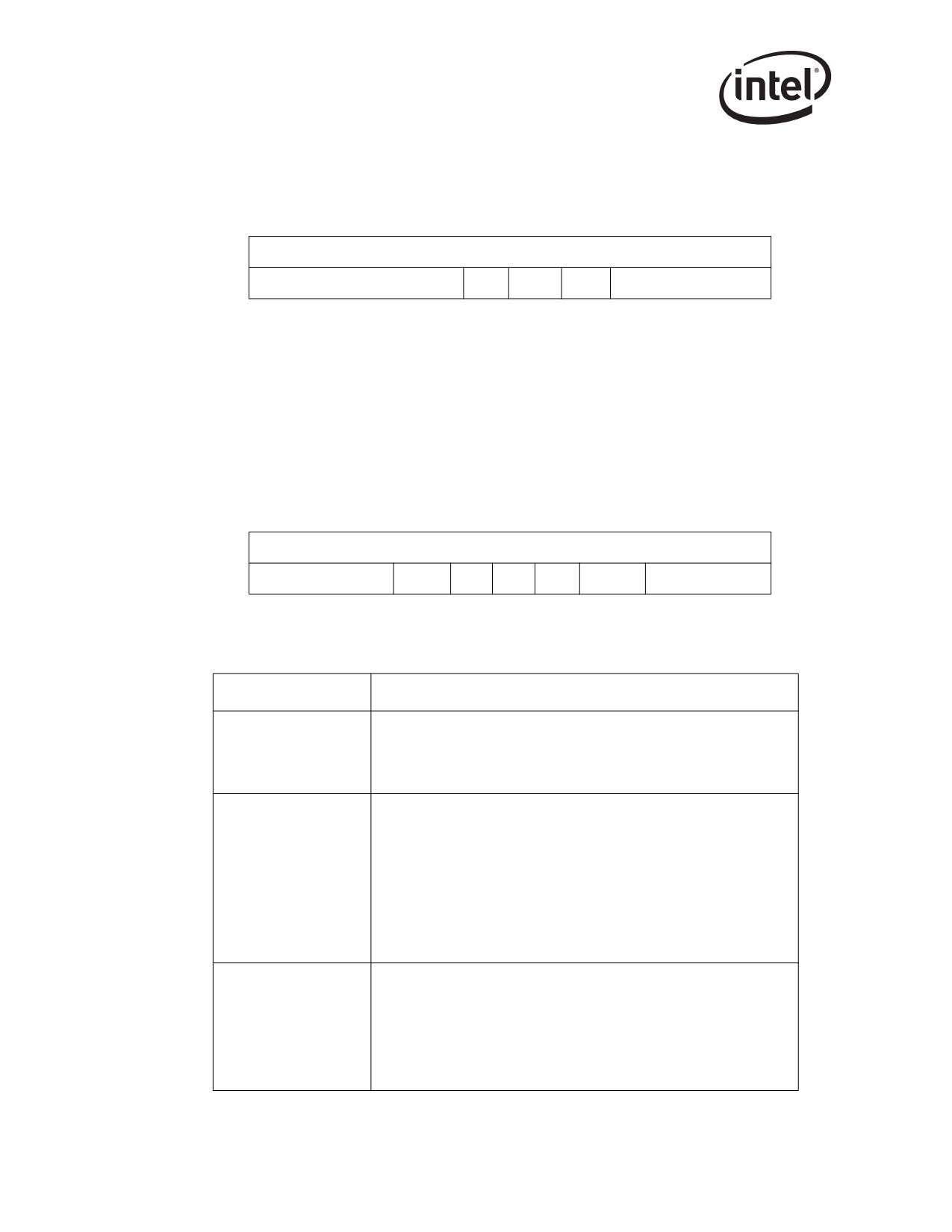
Receive and Transmit Description
Table 3-7. Transmit Descriptor (TDESC) Layout
63
30
29
28
24 23
20 19
0
0
Buffer Address [63:0]
8
NR
DEXT
NR
DTYP
NR
3.3.3
Legacy Transmit Descriptor Format
To select legacy mode operation, bit 29 (TDESC.DEXT) should be set to 0b. In this case, the
descriptor format is defined as shown in Table 3-8. The address and length must be supplied by
software. Bits in the command byte are optional, as are the Checksum Offset (CSO), and
Checksum Start (CSS) fields.
Table 3-8. Transmit Descriptor (TDESC) Layout - Legacy Mode
63
48 47
40 39
36 35
32 31
24 23
16 15
0
0
Buffer Address [63:0]
8
Special
CSS
RSV
STA
CMD
CSO
Length
Table 3-9. Transmit Descriptor Legacy Descriptions
Transmit Descriptor
Description
Legacy
Buffer Address
Address of the transmit descriptor in the host memory. Descriptors with a
Buffer Address
null address transfer no data. If they have the RS bit in the command byte
set (TDESC.CMD), then the DD field in the status word (TDESC.STATUS) is
written when the hardware processes them.
Length is per segment.
The maximum length associated with any single legacy descriptor is 16288
bytes. Although a buffer as short as one byte is allowed, the total length of
the packet, before padding and CRC insertion must be at least 48 bytes.
Length can be up to a default value of 16288 bytes per descriptor, and
Length
16288 bytes total. In other words, the length of the buffer pointed to by one
descriptor, or the sum of the lengths of the buffers pointed to by the
descriptors can be as large as the maximum allowed transmit packet.
Descriptors with zero length transfer no data. If they have the RS bit in the
command byte set (TDESC.CMD), then the DD field in the status word
(TDESC.STATUS) is written when the hardware processes them.
Checksum Offset
The Checksum offset field indicates where, relative to the start of the packet,
to insert a TCP checksum if this mode is enabled. (Insert Checksum bit (IC)
is set in TDESC.CMD). Hardware ignores CSO unless EOP is set in
CSO
TDESC.CMD. CSO is provided in unit of bytes and must be in the range of
the data provided to the Ethernet controller in the descriptor. (CSO < length -
1).
Should be written with 0b for future compatibility.
36

Receive and Transmit Description
Transmit Descriptor
Description
Legacy
Command field
CMD
See Section 3.3.3.1 for a detailed field description.
Status field
STA
See Section 3.3.3.2 for a detailed field description.
Reserved
RSV
Should be written with 0b for future compatibility.
Checksum Start Field
The Checksum start field (TDESC.CSS) indicates where to begin computing
the checksum. The software must compute this offset to back out the bytes
that should not be included in the TCP checksum. CSS is provided in units
CSS
of bytes and must be in the range of data provided to the Ethernet controller
in the descriptor (CSS < length). For short packets that ar padded by the
software, CSS must be in the range of the unpadded data length. A value of
0b corresponds to the first byte in the packet.
CSS must be set in the first descriptor of the packet.
Special Field
Special
See the notes that follow this table for a detailed field description.
Notes:
1.
Even though CSO and CSS are in units of bytes, the checksum calculation typically works on
16-bit words. Hardware does not enforce even byte alignment.
2.
Hardware does not add the 802.1Q EtherType or the VLAN field following the 802.1Q
EtherType to the checksum. So for VLAN packets, software can compute the values to back
out only on the encapsulated packet rather than on the added fields.
3.
Although the Ethernet controller can be programmed to calculate and insert TCP checksum
using the legacy descriptor format as described above, it is recommended that software use the
newer TCP/IP Context Transmit Descriptor Format. This newer descriptor format allows the
hardware to calculate both the IP and TCP checksums for outgoing packets. See Section 3.3.5
for more information about how the new descriptor format can be used to accomplish this task.
37

Receive and Transmit Description
3.3.3.1
Transmit Descriptor Command Field Format
The CMD byte stores the applicable command and has fields shown in Table 3-10.
Table 3-10. Transmit Command (TDESC.CMD) Layout
7
6
5
4
3
2
1
0
RSV
IDE
VLE
DEXT
RS
IC
IFCS
EOP
RPSa
a.
82544GC/EI only.
TDESC.CMD
Description
Interrupt Delay Enable
When set, activates the transmit interrupt delay timer. The Ethernet controller loads
a countdown register when it writes back a transmit descriptor that has RS and IDE
set. The value loaded comes from the IDV field of the Interrupt Delay (TIDV)
register. When the count reaches 0, a transmit interrupt occurs if transmit descriptor
IDE (bit 7)
write-back interrupts (IMS.TXDW) are enabled. Hardware always loads the transmit
interrupt counter whenever it processes a descriptor with IDE set even if it is
already counting down due to a previous descriptor. If hardware encounters a
descriptor that has RS set, but not IDE, it generates an interrupt immediately after
writing back the descriptor. The interrupt delay timer is cleared.
VLAN Packet Enable
When set, indicates that the packet is a VLAN packet and the Ethernet controller
should add the VLAN Ethertype and an 802.1q VLAN tag to the packet. The
Ethertype field comes from the VET register and the VLAN tag comes from the
special field of the TX descriptor. The hardware inserts the FCS/CRC field in that
VLE (bit 6)
case.
When cleared, the Ethernet controller sends a generic Ethernet packet. The IFCS
controls the insertion of the FCS field in that case.
In order to have this capability CTRL.VME bit should also be set, otherwise VLE
capability is ignored. VLE is valid only when EOP is set.
Extension (0b for legacy mode).
DEXT (bit 5)
Should be written with 0b for future compatibility.
Report Packet Sent
When set, the 82544GC/EI defers writing the DD bit in the status byte
(DESC.STATUS) until the packet has been sent, or transmission results in an error
such as excessive collisions. It is used is cases where the software must know that
the packet has been sent, and not just loaded to the transmit FIFO. The 82544GC/
RPS
EI might continue to prefetch data from descriptors logically after the one with RPS
RSV (bit 4)
set, but does not advance the descriptor head pointer or write back any other
descriptor until it sent the packet with the RPS set. RPS is valid only when EOP is
set.
This bit is reserved and should be programmed to 0b for all Ethernet controllers
except the 82544GC/EI.
Report Status
When set, the Ethernet controller needs to report the status information. This ability
may be used by software that does in-memory checks of the transmit descriptors to
RS (bit 3)
determine which ones are done and packets have been buffered in the transmit
FIFO. Software does it by looking at the descriptor status byte and checking the
Descriptor Done (DD) bit.
38

Receive and Transmit Description
TDESC.CMD
Description
Insert Checksum
When set, the Ethernet controller needs to insert a checksum at the offset indicated
by the CSO field. The checksum calculations are performed for the entire packet
IC (bit 2)
starting at the byte indicated by the CCS field. IC is ignored if CSO and CCS are out
of the packet range. This occurs when (CSS length) OR (CSO length - 1). IC is
valid only when EOP is set.
Insert FCS
IFCS (bit 1)
Controls the insertion of the FCS/CRC field in normal Ethernet packets. IFCS is
valid only when EOP is set.
End Of Packet
EOP (bit 0)
When set, indicates the last descriptor making up the packet. One or many
descriptors can be used to form a packet.
Notes:
1.
VLE, IFCS, and IC are qualified by EOP. That is, hardware interprets these bits ONLY when
EOP is set.
2.
Hardware only sets the DD bit for descriptors with RS set.
3.
Descriptors with the null address (0b) or zero length transfer no data. If they have the RS bit
set then the DD field in the status word is written when hardware processes them.
4.
Although the transmit interrupt may be delayed, the descriptor write-back requested by setting
the RS bit is performed without delay unless descriptor write-back bursting is enabled.
3.3.3.2
Transmit Descriptor Status Field Format
The STATUS field stores the applicable transmit descriptor status and has the fields shown in Table
3-11.
The transmit descriptor status field is only present in cases where RS (or RPS for the 82544GC/EI
only) is set in the command field.
Table 3-11. Transmit Status Layout
3
2
1
0
RSV
LC
EC
DD
TUa
a.
82544GC/EI only.
39

Receive and Transmit Description
TDESC.STATUS
Description
Transmit Underrun
Indicates a transmit underrun event occurred. Transmit Underrun might occur if Early
Transmits are enabled (based on ETT.Txthreshold value) and the 82544GC/EI was
not able to complete the early transmission of the packet due to lack of data in the
TU
packet buffer. This does not necessarily mean the packet failed to be eventually
RSV (bit 3)
transmitted. The packet is successfully re-transmitted if the TCTL.NRTU bit is
cleared (and excessive collisions do not occur).
This bit is reserved and should be programmed to 0b for all Ethernet controllers
except the 82544GC/EI.
Late Collision
Indicates that late collision occurred while working in half-duplex mode. It has no
LC (bit 2)
meaning while working in full-duplex mode. Note that the collision window is speed
dependent: 64 bytes for 10/100 Mb/s and 512 bytes for 1000 Mb/s operation.
Excess Collisions
Indicates that the packet has experienced more than the maximum excessive
EC (bit 1)
collisions as defined by TCTL.CT control field and was not transmitted. It has no
meaning while working in full-duplex mode.
Descriptor Done
Indicates that the descriptor is finished and is written back either after the descriptor
DD (bit 0)
has been processed (with RS set) or for the 82544GC/EI, after the packet has been
transmitted on the wire (with RPS set).
Note: The DD bit reflects status of all descriptors up to and including the one with the RS bit set (or RPS
for the 82544GC/EI).
3.3.4
Transmit Descriptor Special Field Format
The SPECIAL field is used to provide the 802.1q/802.1ac tagging information.
When CTRL.VME is set to 1b, all packets transmitted from the Ethernet controller that have VLE
set in the TDESC.CMD are sent with an 802.1Q header added to the packet. The contents of the
header come from the transmit descriptor special field and from the VLAN type register. The
special field is ignored if the VLE bit in the transmit descriptor command field is 0b. The special
field is valid only for descriptors with EOP set to 1b in TDESC.CMD.
Table 3-12. Special Field (TDESC.SPECIAL) Layout
15
13
12
11
0
PRI
CFI
VLAN
TDESC.SPECIAL
Description
User Priority
PRI
3 bits that provide the VLAN user priority field to be inserted in the 802.1Q tag.
CFI
Canonical Form Indicator.
VLAN Identifier
VLAN
12 bits that provide the VLAN identifier field to be inserted in the 802.1Q tag.
40
Receive and Transmit Description
3.3.5
TCP/IP Context Transmit Descriptor Format
The TCP/IP context transmit descriptor provides access to the enhanced checksum offload facility
available in the Ethernet controller. This feature allows TCP and UDP packet types to be handled
more efficiently by performing additional work in hardware, thus reducing the software overhead
associated with preparing these packets for transmission.
The TCP/IP context transmit descriptor does not point to packet data as a data descriptor does.
Instead, this descriptor provides access to an on-chip context that supports the transmit checksum
offloading feature of the controller. A “context” refers to a set of registers loaded or unloaded as a
group to provide a particular function.
The context is explicit and directly accessible via the TCP/IP context transmit descriptor. The
context is used to control the checksum offloading feature for normal packet transmission.
The Ethernet controller automatically selects the appropriate legacy or normal context to use based
on the current packet transmission.
While the architecture supports arbitrary ordering rules for the various descriptors, there are
restrictions including:
• Context descriptors should not occur in the middle of a packet.
• Data descriptors of different packet types (legacy or normal) should not be intermingled
except at the packet level.
All contexts control calculation and insertion of up to two checksums. This portion of the context is
referred to as the checksum context.
In addition to checksum context, the segmentation context adds information specific to the
segmentation capability. This additional information includes the total payload for the message
(TDESC.PAYLEN), the total size of the header (TDESC.HDRLEN), the amount of payload data
that should be included in each packet (TDESC.MSS), and information about what type of protocol
(TCP, IPv4, IPv6, etc.) is used. This information is specific to the segmentation capability and is
therefore ignored for context descriptors that do not have the TSE bit set.
Because there are dedicated resources on-chip for the normal context, the context remains constant
until it is modified by another context descriptor. This means that a context can be used for multiple
packets (or multiple segmentation blocks) unless a new context is loaded prior to each new packet.
Depending on the environment, it may be completely unnecessary to load a new context for each
packet. For example, if most traffic generated from a given node is standard TCP frames, this
context could be set up once and used for many frames. Only when some other frame type is
required would a new context need to be loaded by software. After the “non-standard” frame is
transmitted, the “standard” context would be setup once more by software. This method avoids the
“extra descriptor per packet” penalty for most frames. The penalty can be eliminated altogether if
software elects to use TCP/IP checksum offloading only for a single frame type, and thus performs
those operations in software for other frame types.
This same logic can also be applied to the segmentation context, though the environment is a more
restrictive one. In this scenario, the host is commonly asked to send a message of the same type,
TCP/IP for instance, and these messages also have the same total length and same maximum
segment size (MSS). In this instance, the same segmentation context could be used for multiple
TCP messages that require hardware segmentation. The limitations of this scenario and the
relatively small performance advantage make this approach unlikely; however, it is useful in
understanding the underlying mechanism.
41
Receive and Transmit Description
3.3.6
TCP/IP Context Descriptor Layout
The following section describes the layout of the TCP/IP context transmit descriptor.
To select this descriptor format, bit 29 (TDESC.DEXT) must be set to 1b and TDESC.DTYP must
be set to 0000b. In this case, the descriptor format is defined as shown in Table 3-13.
Note that the TCP/IP context descriptor does not transfer any packet data. It merely prepares the
checksum hardware for the TCP/IP Data descriptors that follow.
Table 3-13. Transmit Descriptor (TDESC) Layout - (Type = 0000b)
63
48 47
40 39
32 31
16 15
87
0
0
TUCSE
TUCSO
TUCSS
IPCSE
IPCSO
IPCSS
8
MSS
HDRLEN
RSV
STA
TUCMD
DTYP
PAYLEN
63
48 47
40 39
36 35
32 31
24 23
20 19
0
Note: The first quadword of this descriptor type contains parameters used to calculate the two checksums
which may be offloaded.
42

Receive and Transmit Description
Table 3-14. Transmit Descriptor (TDESC) Layout
Transmit
Description
Descriptor Offload
TCP/UDP Checksum Ending
Defines the ending byte for the TCP/UDP checksum offload feature.
TUCSE
Setting TUCSE field to 0b indicates that the checksum covers from TUCCS to the
end of the packet.
TCP/UDP Checksum Offset
Defines the offset where to insert the TCP/UDP checksum field in the packet data
buffer. This is used in situations where the software needs to calculate partial
TUCSO
checksums (TCP pseudo-header, for example) to include bytes which are not
contained within the range of start and end.
If no partial checksum is required, software must write a value of 0b.
TCP/UDP Checksum Start
Defines the starting byte for the TCP/UDP checksum offload feature.
TUCSS
It must be defined even if checksum insertion is not desired for some reason.
When setting the TCP segmentation context, TUCSS is used to indicate the start
of the TCP header.
IP Checksum Ending
Defines the ending byte for the IP checksum offload feature.
It specifies where the checksum should stop. A 16-bit value supports checksum
IPCSE
offloading of packets as large as 64KB.
Setting IPCSE field to 0b indicates that the checksum covers from IPCCS to the
end of the packet. In this way, the length of the packet does not need to be
calculated.
IP Checksum Offset
The IPCSO field specifies where the resulting IP checksum should be placed. It is
IPCSO
limited to the first 256 bytes of the packet and must be less than or equal to the
total length of a given packet. If this is not the case, the checksum is not inserted.
IP Checksum Start
IPCSS specifies the byte offset from the start of the transferred data to the first
byte in be included in the checksum. Setting this value to 0b means the first byte of
the data would be included in the checksum.
Note that the maximum value for this field is 255. This is adequate for typical
IPCSS
applications.
The IPCSS value needs to be less than the total transferred length of the packet. If
this is not the case, the results are unpredictable.
IPCSS must be defined even if checksum insertion is not desired for some reason.
When setting the TCP segmentation context, IPCSS is used to indicate the start of
the IP header.
Maximum Segment Size
Controls the Maximum Segment Size. This specifies the maximum TCP or UDP
payload “segment” sent per frame, not including any header. The total length of
MSS
each frame (or “section”) sent by the TCP Segmentation mechanism (excluding
802.3ac tagging and Ethernet CRC) is MSS bytes + HRDLEN. The one exception
is the last packet of a TCP segmentation context which is (typically) shorter than
“MSS+HDRLEN”. This field is ignored if TDESC.TSE is not set.
Header Length
Specifies the length (in bytes) of the header to be used for each frame (or
“section”) of a TCP Segmentation operation. The first HDRLEN bytes fetched from
data descriptor(s) are stored internally and used as a prototype header for each
HDRLEN
section, and are pre-pended to each payload segment to form individual frames.
For UDP packets this is normally equal to “UDP checksum offset + 2”. For TCP
packets it is normally equal to “TCP checksum offset + 4 + TCP header option
bytes”. This field is ignored if TDESC.TSE is not set.
43

Receive and Transmit Description
Transmit
Description
Descriptor Offload
Reserved
RSV
Should be programmed to 0b for future compatibility.
TCP/UDP Status field
STA
Provides transmit status indication.
Section 3.3.6.2 provides the bit definition for the TDESC.STA field.
TCP/UDP command field
The command field provides options that control the checksum offloading, along
TUCMD
with some of the generic descriptor processing functions.
Section 3.3.6.1 provides the bit definitions for the TDESC.TUCMD field.
Descriptor Type
DTYP
Set to 0000b for TCP/IP context transmit descriptor type.
The packet length field (TDESC.PAYLEN) is the total number of payload bytes for
this TCP Segmentation offload context (i.e., the total number of payload bytes that
could be distributed across multiply frames after TCP segmentation is performed).
Following the fetch of the prototype header, PAYLEN specifies the length of data
that is fetched next from data descriptor(s). This field is also used to determine
when “last-frame” processing needs to be performed. Typically, a new data
PAYLEN
descriptor is used to denote the start of the payload data buffer(s), but this is not
required. PAYLEN specification should not include any header bytes. There is no
restriction on the overall PAYLEN specification with respect to the transmit FIFO
size, once the MSS and HDRLEN specifications are legal. This field is ignored if
TDESC.TSE is not set. Refer to Section 3.5 for details on the TCP Segmentation
off-loading feature.
Notes:
1.
A number of the fields are ignored if the TCP Segmentation enable bit (TDESC.TSE) is
cleared, denoting that the descriptor does not refer to the TCP segmentation context.
2.
Maximum limits for the HDRLEN and MSS fields are dictated by the lengths variables. How-
ever, there is a further restriction that for any TCP Segmentation operation, the hardware must
be capable of storing a complete section (completely-built frame) in the transmit FIFO prior to
transmission. Therefore, the sum of MSS + HDRLEN must be at least 80 bytes less than the
allocated size of the transmit FIFO.
3.3.6.1
TCP/UDP Offload Transmit Descriptor Command Field
The command field (TDESC.TUCMD) provides options to control the TCP segmentation, along
with some of the generic descriptor processing functions.
44

Receive and Transmit Description
Table 3-15. Command Field (TDESC.TUCMD) Layout
7
6
5
4
3
2
1
0
IDE
RSV
DEXT
RSV
RS
TSE
IP
TCP
TDESC.TUCMD
Description
Interrupt Delay Enable
IDE activates the transmit interrupt delay timer. Hardware loads a countdown
register when it writes back a transmit descriptor that has the RS bit and the IDE bit
set. The value loaded comes from the IDV field of the Interrupt Delay (TIDV) register.
IDE (bit 7)
When the count reaches 0, a transmit interrupt occurs. Hardware always loads the
transmit interrupt counter whenever it processes a descriptor with IDE set even if it is
already counting down due to a previous descriptor. If hardware encounters a
descriptor that has RS set, but not IDE, it generates an interrupt immediately after
writing back the descriptor. The interrupt delay timer is cleared.
RSV (Bit 6)
Reserved. Set to 0b for future compatibility.
Descriptor Extension
DEXT(Bit 5)
Must be 1b for this descriptor type.
RSV (Bit 4)
Reserved. Set to 0b for future compatibility.
Report Status
RS tells the hardware to report the status information for this descriptor. Because this
RS (Bit 3)
descriptor does not transmit data, only the DD bit in the status word is valid. Refer to
Section 3.3.6.2 for the layout of the status field.
TCP Segmentation Enable
TSE indicates that this descriptor is setting the TCP segmentation context. If this bit
is not set, the checksum offloading context for normal (non-”TCP Segmentation”)
packets is written. When a descriptor of this type is processed the Ethernet controller
TSE (Bit 2)
immediately updates the context in question (TCP Segmentation or checksum
offloading) with values from the descriptor. This means that if any normal packets or
TCP Segmentation packets are in progress (a descriptor with EOP set has not been
received for the given context), the results are likely to be undesirable.
Packet Type (IPv4 = 1b, IPv6 = 0b)
Identifies what type of IP packet is used in the segmentation process. This is
IP (Bit 1)
necessary for hardware to know where the IP Payload Length field is located. This
does not override the checksum insertion bit, IXSM.
Packet Type (IP = 1b)
IP (Bit 1)
Identifies the packet as an IP packet. The purpose of this bit is to enable/disable the
82544GC/EI only
updating of the IP header during the segmentation process. This does not override
the checksum insertion bit, IXSM.
Packet Type (TCP = 1b)
TCP (bit 0)
Identifies the packet as either TCP or UDP (non-TCP). This affects the processing of
the header information.
Note:
1.
The IDE, DEXT, and RS bits are valid regardless of the state of TSE. All other bits are ignored
if TSE = 0b.
2.
The TCP Segmentation feature also provides access to a generic block send function and may
be useful for performing “segmentation offload” in which the header information is constant.
By clearing both the TCP and IP bits, a block of data may be broken down into frames of a
given size, a constant, arbitrary length header may be pre-pended to each frame, and two
checksums optionally added.
45

Receive and Transmit Description
3.3.6.2
TCP/UDP Offload Transmit Descriptor Status Field
Four bits are reserved to provide transmit status, although only one is currently assigned for this
specific descriptor type. The status word is only written back to host memory in cases where the RS
is set in the command.
Table 3-16. Transmit Status Layout
3
2
1
0
RSV
DD
TDESC.STA
Description
Reserved
RSV
Reserved for future use. Reads as 0b.
Descriptor Done
DD (bit 0)
Indicates that the descriptor is finished and is written back after the descriptor has
been processed.
3.3.7
TCP/IP Data Descriptor Format
The TCP/IP data descriptor is the companion to the TCP/IP context transmit descriptor described
in the previous section. This descriptor type provides similar functionality to the legacy mode
descriptor but also integrates the checksum offloading and TCP Segmentation feature.
To select this descriptor format, bit 29 in the command field (TDESC.DEXT) must be set to 1b and
TDESC.DTYP must be set to 0001b. In this case, the descriptor format is defined as shown in
Table 3-17.
46

Receive and Transmit Description
Table 3-17. Transmit Descriptor (TDESC) Layout - (Type = 0001b)
0
Address [63:0]
8
Special
POPTS
RSV
STA
DCMD
DTYP
DTALEN
0
63
48 47
40 39 36 35
32 31
24 23
20 19
0
Transmit Descriptor
Description
Data buffer address
Address
Address of the data buffer in the host memory which contains a portion of the
transmit packet.
Data Length Field
Total length of the data pointed to by this descriptor, in bytes.
For data descriptors not associated with a TCP Segmentation operation
DTALEN
(TDESC.TSE not set), the descriptor lengths are subject to the same restrictions
specified for legacy descriptors (the sum of the lengths of the data descriptors
comprising a single packet must be at least 80 bytes less than the allocated size
of the transmit FIFO.)
Data Type
DTYP
Set to 0001b to identify this descriptor as a TCP/IP data descriptor.
Descriptor Command Field
DCMD
Provides options that control some of the generic descriptor processing
features. Refer to Section 3.3.7.1 for bit definitions of the DCMD field.
TCP/IP Status field
STA
Provides transmit status indication.
Section 3.3.7.2 provides the bit definition for the TDESC.STA field.
Reserved
RSV
Set to 0b for future compatibility.
Packet Option Field
Provides a number of options which control the handling of this packet. This field
POPTS
is ignored except on the first data descriptor of a packet.
Section 3.3.7.3 provides the bit definition for the TDESC.POPTS field.
Special field
The Special field is used to provide 802.1q tagging information.
Special
This field is only valid in the last descriptor of the given packet (qualified by the
EOP bit).
47

Receive and Transmit Description
3.3.7.1
TCP/IP Data Descriptor Command Field
The Command field provides options that control checksum offloading and TCP segmentation
features along with some of the generic descriptor processing features.
Table 3-18. Command Field (TDESC.DCMD) Layout
7
6
5
4
3
2
1
0
RSV
IDE
VLE
DEXT
RS
TSE
IFCS
EOP
RPSa
a.
82544GC/EI only.
TDESC.DCMD
Description
Interrupt Delay Enable
When set, activates the transmit interrupt delay timer. Hardware loads a countdown
register when it writes back a transmit descriptor that has RS and IDE set. The value
loaded comes from the IDV field of the Interrupt Delay (TIDV) register. When the
IDE (bit 7)
count reaches 0, a transmit interrupt occurs if enabled. Hardware always loads the
transmit interrupt counter whenever it processes a descriptor with IDE set even if it is
already counting down due to a previous descriptor. If hardware encounters a
descriptor that has RS set, but not IDE, it generates an interrupt immediately after
writing back the descriptor. The interrupt delay timer is cleared.
VLAN Enable
When set, indicates that the packet is a VLAN packet and the hardware should add
the VLAN Ethertype and an 802.1q VLAN tag to the packet. The Ethertype should
come from the VET register and the VLAN data comes from the special field of the TX
descriptor. The hardware in that case appends the FCS/CRC.
VLE (bit 6)
Note that the CTRL.VME bit should also be set. If the CTRL.VME bit is not set, the
Ethernet controller does not insert VLAN tags on outgoing packets and it sends
generic Ethernet packets. The IFCS controls the insertion of the FCS/CRC in that
case.
VLE is only valid in the last descriptor of the given packet (qualified by the EOP bit).
Descriptor Extension
DEXT (Bit 5)
Must be 1b for this descriptor type
Report Packet Sent
RPS is used in cases where software must know that a packet has been sent on the
wire, not just that it has been loaded into the 82544GC/EI controller’s internal packet
buffer.
When set, hardware defers writing the DD bit in the status byte until the packet has
been sent, or transmission results in an error such as excess collisions. Hardware
RPS
can continue to pre-fetch data from descriptors logically after the one with RPS set,
RSV (bit 4)
but does not advance the head pointer or write back any other descriptors until it has
sent the packet with RPS set.
For a TCP Segmentation context, the RPS bit indicates to the 82544GC/EI that the
descriptor status should only be written back once all packets that make up the given
TCP Segmentation context had been sent.
This bit is reserved and should be programmed to 0b for all Ethernet controllers
except the 82544GC/EI.
Report Status
When set, tells the hardware to report the status information for this descriptor as
RS (bit 3)
soon as the corresponding data buffer has been fetched and stored in the controller’s
internal packet buffer.
48

Receive and Transmit Description
TDESC.DCMD
Description
TCP Segmentation Enable
TSE (bit 2)
TSE indicates that this descriptor is part of the current TCP Segmentation context. If
this bit is not set, the descriptor is part of the “normal” context.
Insert IFCS
IFCS (Bit 1)
Controls the insertion of the FCS/CRC field in normal Ethernet packets.
IFCS is only valid in the last descriptor of the given packet (qualified by the EOP bit).
End Of Packet
The EOP bit indicates that the buffer associated with this descriptor contains the last
data for the packet or for the given TCP Segmentation context. In the case of a TCP
EOP (Bit 0)
Segmentation context, the DTALEN length of this descriptor should match the
amount remaining of the original PAYLEN. If it does not, the TCP Segmentation
context is terminated but the end of packet processing may be incorrectly performed.
These abnormal termination events are counted in the TSCTFC statistics register.
Note:
The VLE, IFCS, and VLAN fields are only valid in certain descriptors. If TSE is enabled, the VLE,
IFCS, and VLAN fields are only valid in the first data descriptor of the TCP segmentation context.
If TSE is not enabled, then these fields are only valid in the last descriptor of the given packet
(qualified by the EOP bit).
3.3.7.2
TCP/IP Data Descriptor Status Field
Four bits are reserved to provide transmit status, although only the DD is valid1. The status word is
only written back to host memory in cases where the RS bit is set in the command field. The DD bit
indicates that the descriptor is finished and is written back after the descriptor has been processed.
Table 3-19. Transmit Status Layout
3
2
1
0
RSV
LC
EC
DD
TUa
a.
82544GC/EI only.
TDESC.STA
Description
Reserved
Reserved
1. Unless the RPS bit is set in the descriptor (82544GC/EI only).
49

Receive and Transmit Description
TDESC.STA
Description
Late Collision
Indicates that late collision occurred while working in half-duplex mode.
LC (bit2)
It has no meaning while working in full-duplex mode.
Note that the collision window is speed dependent: 64 bytes for 10/100 Mb/s and
512 bytes for 1000 Mb/s operation.
Excess Collision
Indicates that the packet has experienced more than the maximum excessive
EC (bit 1)
collisions as defined by TCTL.CT control field and was not transmitted.
Is has no meaning while working in full-duplex mode.
Descriptor Done
Indicates that the descriptor is done and is written back either after the descriptor
DD (bit 0)
has been processed (with RS set), or for the 82554GC/EI only, after the packet has
been transmitted on the wire (with RPS set).
3.3.7.3
TCP/IP Data Descriptor Option Field
The POPTS field provides a number of options which control the handling of this packet. This field
is ignored except on the first data descriptor of a packet.
Table 3-20. Packet Options Field (TDESC.POPTS) Layout
7
6
5
4
3
2
1
0
RSV
RSV
RSV
RSV
RSV
RSV
TXSM
IXSM
TDESC.POPTS
Description
Reserved
RSV (bit 2-7)
Should be written with 0b for future compatibility.
Insert TCP/UDP Checksum
Controls the insertion of the TCP/UDP checksum.
If not set, the value placed into the checksum field of the packet data is not modified,
TXSM (bit1)
and is placed on the wire. When set, TCP/UDP checksum field is modified by the
hardware.
Valid only in the first data descriptor for a given packet or TCP Segmentation context.
Insert IP Checksum
Controls the insertion of the IP checksum.
If not set, the value placed into the checksum field of the packet data is not modified
IXSM (bit 0)
and is placed on the wire. When set, the IP checksum field is modified by the
hardware.
Valid only in the first data descriptor for a given packet or TCP Segmentation context.
3.3.7.4
TCP/IP Data Descriptor Special Field
The SPECIAL field is used to provide the 802.1q/802.3ac tagging information.
50

Receive and Transmit Description
When CTRL.VME is set to 1b, all packets transmitted from the Ethernet controller that has VLE
set in the DCMD field is sent with an 802.1Q header added to the packet. The contents of the
header come from the transmit descriptor special field and from the VLAN type register. The
special field is ignored if the VLE bit in the transmit descriptor command field is 0b. The special
field is valid only when EOP is set.
Table 3-21. Special Field (TDESC.SPECIAL) Layout
15
13
12
11
0
PRI
CFI
VLAN
TDESC.SPECIAL
Description
User Priority
PRI
Three bits that provide the VLAN user priority field to be inserted in the 802.1Q tag.
CFI
Canonical Form Indicator
VLAN Identifier
VLAN
12 bits that provide the VLAN identifier field to be inserted in the 802.1Q tag.
3.4
Transmit Descriptor Ring Structure
The transmit descriptor ring structure is shown in Figure 3-4. A pair of hardware registers
maintains the transmit queue. New descriptors are added to the ring by writing descriptors into the
circular buffer memory region and moving the ring’s tail pointer. The tail pointer points one entry
beyond the last hardware owned descriptor (but at a point still within the descriptor ring).
Transmission continues up to the descriptor where head equals tail at which point the queue is
empty.
Descriptors passed to hardware should not be manipulated by software until the head pointer has
advanced past them.
51
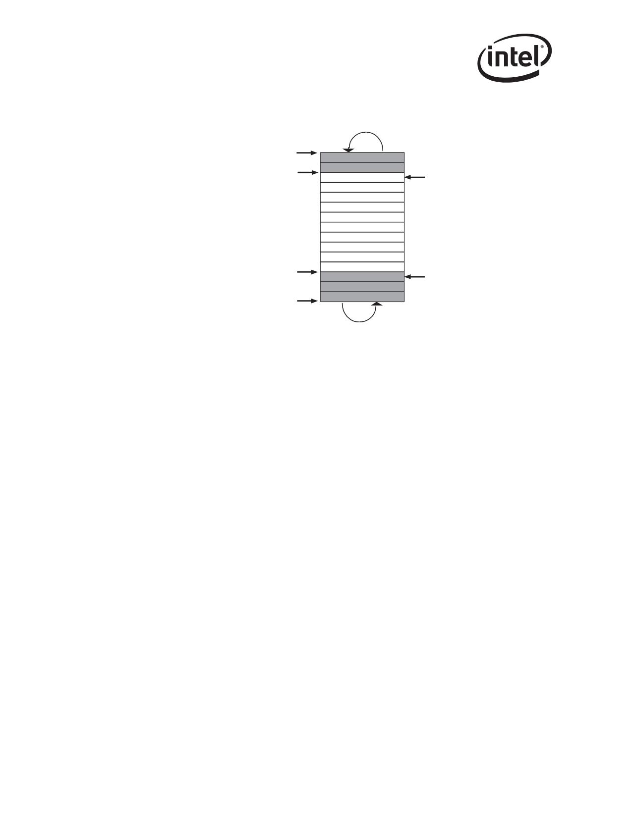
Receive and Transmit Description
Circular Buffer
Base
Head
Owned By
Transmit
Hardware
Queue
Tail
Base + Size
Figure 3-4. Transmit Descriptor Ring Structure
Shaded boxes in Figure 3-4 represent descriptors that have been transmitted but not yet reclaimed
by software. Reclaiming involves freeing up buffers associated with the descriptors.
The transmit descriptor ring is described by the following registers:
• Transmit Descriptor Base Address registers (TDBAL and TDBAH)
These registers indicate the start of the descriptor ring buffer. This 64-bit address is aligned on
a 16-byte boundary and is stored in two consecutive 32-bit registers. TDBAL contains the
lower 32-bits; TDBAH contains the upper 32 bits. Hardware ignores the lower 4 bits in
TDBAL.
• Transmit Descriptor Length register (TDLEN)
This register determines the number of bytes allocated to the circular buffer. This value must
be 128 byte aligned.
• Transmit Descriptor Head register (TDH)
This register holds a value which is an offset from the base, and indicates the in-progress
descriptor. There can be up to 64K descriptors in the circular buffer. Reading this register
returns the value of “head” corresponding to descriptors already loaded in the output FIFO.
• Transmit Descriptor Tail register (TDT)
This register holds a value which is an offset from the base, and indicates the location beyond
the last descriptor hardware can process. This is the location where software writes the first
new descriptor.
The base register indicates the start of the circular descriptor queue and the length register indicates
the maximum size of the descriptor ring. The lower seven bits of length are hard-wired to 0b. Byte
addresses within the descriptor buffer are computed as follows:
address = base + (ptr * 16), where ptr is the value in the hardware head or tail register.
The size chosen for the head and tail registers permit a maximum of 64 K descriptors, or
approximately 16 K packets for the transmit queue given an average of four descriptors per packet.
52
Receive and Transmit Description
Once activated, hardware fetches the descriptor indicated by the hardware head register. The
hardware tail register points one beyond the last valid descriptor.
Software can determine if a packet has been sent by setting the RS bit (or the RPS bit for the
82544GC/EI only) in the transmit descriptor command field. Checking the transmit descriptor DD
bit in memory eliminates a potential race condition. All descriptor data is written to the IO bus
prior to incrementing the head register, but a read of the head register could “pass” the data write in
systems performing IO write buffering. Updates to transmit descriptors use the same IO write path
and follow all data writes. Consequently, they are not subject to the race condition. Other potential
conditions also prohibit software reading the head pointer.
In general, hardware prefetches packet data prior to transmission. Hardware typically updates the
value of the head pointer after storing data in the transmit FIFO1.
The process of checking for completed packets consists of one of the following:
• Scan memory for descriptor status write-backs.
• Take an interrupt. An interrupt condition can be generated whenever a transmit queue goes
empty (ICR.TXQE). Interrupts can also be triggered in other ways.
3.4.1
Transmit Descriptor Fetching
The descriptor processing strategy for transmit descriptors is essentially the same as for receive
descriptors except that a different set of thresholds are used. As for receives, the number of on-chip
transmit descriptors buffer space is 64 descriptors.
When the on-chip buffer is empty, a fetch happens as soon as any descriptors are made available
(software writes to the tail pointer). When the on-chip buffer is nearly empty
(TXDCTL.PTHRESH), a prefetch is performed whenever enough valid descriptors
(TXDCTL.HTHRESH) are available in host memory and no other DMA activity of greater priority
is pending (descriptor fetches and write-backs or packet data transfers).
The descriptor prefetch policy is aggressive to maximize performance. If descriptors reside in an
external cache, the system must ensure cache coherency before changing the tail pointer.
When the number of descriptors in host memory is greater than the available on-chip descriptor
storage, the chip may elect to perform a fetch which is not a multiple of cache line size. The
hardware performs this non-aligned fetch if doing so results in the next descriptor fetch being
aligned on a cache line boundary. This allows the descriptor fetch mechanism to be most efficient
in the cases where it has fallen behind software.
3.4.2
Transmit Descriptor Write-back
The descriptor write-back policy for transmit descriptors is similar to that for receive descriptors
with a few additional factors. First, since transmit descriptor write-backs are optional (controlled
by RS2 in the transmit descriptor), only descriptors which have one (or both) of these bits set starts
the accumulation of write-back descriptors. Secondly, to preserve backward compatibility with the
82542, if the TXDCTL.WTHRESH value is 0b, the Ethernet controller writes back a single byte of
the descriptor (TDESCR.STA) and all other bytes of the descriptor are left unchanged.
1. With the RPS bit set, the head is not advanced until after the packet is transmitted or rejected due to excess collisions (82544GC/EI only).
2. And RPS for the 82544GC/EI only.
53
Receive and Transmit Description
Since the benefit of delaying and then bursting transmit descriptor write-backs is small at best, it is
likely that the threshold are left at the default value (0b) to force immediate write-back of transmit
descriptors and to preserve backward compatibility.
Descriptors are written back in one of three conditions:
• TXDCTL.WTHRESH = 0b and a descriptor which has RS1 set is ready to be written back
• Transmit Interrupt Delay timer expires
• TXDCTL.WTHRESH > 0b and TXDCTL.WTHRESH descriptors have accumulated
For the first condition, write-backs are immediate. This is the default operation and is backward
compatible. For this case, the Transmit Interrupt delay function works as described in Section
3.4.3.1.
The other two conditions are only valid if descriptor bursting is enabled (see Section 13.4.44). In
the second condition, the Transmit Interrupt Delay timer (TIDV) is used to force timely write-back
of descriptors. The first packet after timer initialization starts the timer. Timer expiration flushes
any accumulated descriptors and sets an interrupt event (TXDW).
For the final condition, if TXDCTL.WTHRESH descriptors are ready for write-back, the write-
back is performed.
3.4.3
Transmit Interrupts
Hardware supplies three transmit interrupts. These interrupts are initiated through the following
conditions:
• Transmit queue empty (TXQE) - All descriptors have been processed. The head pointer is
equal to the tail pointer.
• Descriptor done [Transmit Descriptor Write-back (TXDW)] - Set when hardware writes
back a descriptor with RS1 set. This is only expected to be used in cases where, for example,
the streams interface has run out of descriptors and wants to be interrupted whenever progress
is made.
• Transmit Delayed Interrupt (TXDW) - In conjunction with IDE (Interrupt Delay Enable), the
TXDW indication is delayed by a specific time per the TIDV register. This interrupt is set
when the transmit interrupt countdown register expires. The countdown register is loaded with
the value of the IDV field of the TIDV register, when a transmit descriptor with its RS1 bit and
the IDE bit are set, is written back. When a Transmit Delayed Interrupt occurs, the TXDW
interrupt cause bit is set (just as when a Transmit Descriptor Write-back interrupt occurs). This
interrupt may be masked in the same manner as the TXDW interrupt. This interrupt is used
frequently by software that performs dynamic transmit chaining, by adding packets one at a
time to the transmit chain.
Note: The transmit delay interrupt is indicated with the same interrupt bit as the transmit write-back
interrupt, TXDW. The transmit delay interrupt is only delayed in time as discussed above.
1. Or RPS for the 82544GC/EI only.
54
Receive and Transmit Description
• Link status change (LSC) - Set when the link status changes. When using the internal PHY,
link status changes are determined and indicated by the PHY via a change in its LINK
indication.
When using an external TBI device (82544GC/EI only), the device might indicate a link
status change using its LOS (loss of sync) indication. In this TBI mode, if HW Auto-
Negotiation is enabled, the MAC can also detect and signal a link status change if the
Configuration Base Page register is received (0b), or if either the LRST or ANE bits are
changed by software.
• Transmit Descriptor Ring Low Threshold Hit (TXD_LOW) (not applicable to the 82544GC/
EI) - Set when the total number of transmit descriptors available (as measured by the
difference between the Tx descriptor ring Head and Tail pointer) hits the low threshold
specified in the TXDCTL.LWTHRESH field.
3.4.3.1
Delayed Transmit Interrupts
This mechanism allows software the flexibility of delaying transmit interrupts until no more
descriptors are added to a transmit chain for a certain amount of time, rather than when the Ethernet
controller’s head pointer catches the tail pointer. This occurs if the Ethernet controller is processing
packets slightly faster than the software, a likely scenario for gigabit operations.
A software driver usually has no knowledge of when it is going to be asked to send another frame.
For performance reasons, it is best to generate only one transmit interrupt after a burst of packets
have been sent.
Refer to Section 3.3.3.1 for specific details.
3.5
TCP Segmentation
Hardware TCP Segmentation is one of the off-loading options of most modern TCP/IP stacks. This
is often referred to as “Large Send” offloading. This feature enables the TCP/IP stack to pass to the
Ethernet controller software driver a message to be transmitted that is bigger than the Maximum
Transmission Unit (MTU) of the medium. It is then the responsibility of the software driver and
hardware to carve the TCP message into MTU size frames that have appropriate layer 2 (Ethernet),
3 (IP), and 4 (TCP) headers. These headers must include sequence number, checksum fields,
options and flag values as required. Note that some of these values (such as the checksum values)
are unique for each packet of the TCP message, and other fields such as the source IP address is
constant for all packets associated with the TCP message.
The offloading of these processes from the software driver to the Ethernet controller saves
significant CPU cycles. The software driver shares the additional tasks to support these options
with the Ethernet controller.
Although the Ethernet controller’s TCP segmentation offload implementation was specifically
designed to take advantage of new “TCP Segmentation offload” features, the hardware
implementation was made generic enough so that it could also be used to “segment” traffic from
other protocols. For instance this feature could be used any time it is desirable for hardware to
segment a large block of data for transmission into multiple packets that contain the same generic
header.
55
Receive and Transmit Description
3.5.1
Assumptions
The following assumption applies to the TCP Segmentation implementation in the Ethernet
controller:
• The RS bit operation is not changed. Interrupts are set after data in buffers pointed to by
individual descriptors is transferred to hardware.
• Checksums are not accurate above a 12 K frame size.
• The function of the RPS1 bit in the Transmit Descriptor is applicable to all of the packets that
make up the “TCP Segmentation” context, not the individual packets segmented by hardware.
3.5.2
Transmission Process
The transmission process for regular (non-TCP Segmentation packets) involves:
• The protocol stack receives from an application a block of data that is to be transmitted.
• The protocol stack calculates the number of packets required to transmit this block based on
the MTU size of the media and required packet headers.
• For each packet of the data block:
• Ethernet, IP and TCP/UDP headers are prepared by the stack.
• The stack interfaces with the software device driver and commands the driver to send the
individual packet.
• The driver gets the frame and interfaces with the hardware.
• The hardware reads the packet from host memory (via DMA transfers).
• The driver returns ownership of the packet to the operating system when the hardware has
completed the DMA transfer of the frame (indicated by an interrupt).
The transmission process for the Ethernet controller TCP segmentation offload implementation
involves:
• The protocol stack receives from an application a block of data that is to be transmitted.
• The stack interfaces to the software device driver and passes the block down with the
appropriate header information.
• The software device driver sets up the interface to the hardware (via descriptors) for the TCP
Segmentation context.
• The hardware transfers the packet data and performs the Ethernet packet segmentation and
transmission based on offset and payload length parameters in the TCP/IP context descriptor
including:
- Packet encapsulation
- Header generation & field updates including IP and TCP/UDP checksum generation
- The driver returns ownership of the block of data to the operating system when the
hardware has completed the DMA transfer of the entire data block (indicated by an
interrupt).
1.
82544GC/EI only.
56
Receive and Transmit Description
3.5.2.1
TCP Segmentation Data Fetch Control
To perform TCP Segmentation in the Ethernet controller, the DMA unit must ensure that the entire
payload of the segmented packet fits into the available space in the on-chip Packet Buffer. The
segmentation process is performed without interruption. The DMA performs various comparisons
between the payload and the Packet Buffer to ensure that no interruptions occur. The TCP
Segmentation Pad & Minimum Threshold (TSPMT) register is used to allow software to program
the minimum threshold required for a TCP Segmentation payload. Consideration should be made
for the MTU value when writing this field. The TSPMT register is also used to program the
threshold padding overhead. This padding is necessary due to the indeterminate nature of the MTU
and the associated headers.
3.5.3
TCP Segmentation Performance
Performance improvements for a hardware implementation of TCP Segmentation offload mean:
• The operating system stack does not need to partition the block to fit the MTU size, saving
CPU cycles.
• The operating system stack only computes one Ethernet, IP, and TCP header per segment,
saving CPU cycles.
• The operating system stack interfaces with the software device driver only once per block
transfer, instead of once per frame.
• Larger PCI bursts are used which improves bus efficiency.
• Interrupts are easily reduced to one per TCP message instead of one per packet.
• Fewer I/O accesses are required to command the hardware.
3.5.4
Packet Format
Typical TCP/IP transmit window size is 8760 bytes (about 6 full size frames). A TCP message can
be as large as 64 KB and is generally fragmented across multiple pages in host memory. The
Ethernet controller partitions the data packet into standard Ethernet frames prior to transmission.
The Ethernet controller supports calculating the Ethernet, IP, TCP, and even UDP headers,
including checksum, on a frame by frame basis.
Ethernet
IPv4
TCP/UDP
DATA
FCS
Figure 3-5. TCP/IP Packet Format
Frame formats supported by the Ethernet controller’s TCP segmentation include:
• Ethernet 802.3
• IEEE 802.1q VLAN (Ethernet 802.3ac)
• Ethernet Type 2
• Ethernet SNAP
• IPv4 headers with options
• IPv6 headers with IP option next headers
• IPv6 packet tunneled in IPv4
57
Receive and Transmit Description
• TCP with options
• UDP with limitations.
UDP (unlike TCP) is not a “reliable protocol”, and fragmentation is not supported at the UDP
level. UDP messages that are larger than the MTU size of the given network medium are normally
fragmented at the IP layer. This is different from TCP, where large TCP messages can be
fragmented at either the IP or TCP layers depending on the software implementation. The Ethernet
controller has the ability to segment UDP traffic (in addition to TCP traffic). This process has
limited usefulness.
IP tunneled packets are not supported for TCP Segmentation operation1.
3.5.5
TCP Segmentation Indication
Software indicates a TCP Segmentation transmission context to the hardware by setting up a TCP/
IP Context Transmit Descriptor. The purpose of this descriptor is to provide information to the
hardware to be used during the TCP segmentation offload process. The layout of this descriptor is
reproduced in Section 3.3.6.
63
48
47
40
39
32
31
16
15
8
7
0
0
TUCSE
TUCS0
TUCSS
IPCSE
IPCS0
IPCSS
8
MSS
HDRLEN
RSV
STA
TUCMD
DTYP
PAYLEN
63
48
47
40
3936
3532
31
24
23
20
19
0
7
6
5
4
3
2
1
0
IDE
RSV
DEXT
RSV
RS
TSE
IP
TCP
Figure 3-6. TCP/IP Context Transmit Descriptor & Command Layout
Setting the TSE bit in the Command field to 1b indicates that this descriptor refers to the TCP
Segmentation context (as opposed to the normal checksum offloading context). This causes the
checksum offloading, packet length, header length, and maximum segment size parameters to be
loaded from the descriptor into the Ethernet controller.
The TCP Segmentation prototype header is taken from the packet data itself. Software must
identity the type of packet that is being sent (IP/TCP, IP/UDP, other), calculate appropriate
checksum offloading values for the desired checksums, and calculate the length of the header
which is pre-pended. The header may be up to 240 bytes in length.
Once the TCP Segmentation context has been set, the next descriptor provides the initial data to
transfer. This first descriptor(s) must point to a packet of the type indicated. Furthermore, the data it
points to may need to be modified by software as it serves as the prototype header for all packets
within the TCP Segmentation context. The following sections describe the supported packet types
and the various updates which are performed by hardware. This should be used as a guide to
determine what must be modified in the original packet header to make it a suitable prototype
header.
The following summarizes the fields considered by the driver for modification in constructing the
prototype header:
58
Receive and Transmit Description
• IPv4 Header
- Length should be set to zero
- Identification Field should be set as appropriate for first packet of send (if not already)
- Header Checksum should be zeroed out unless some adjustment is needed by the driver
• IPv6 Header
- Length should be set to zero
• TCP Header
- Sequence Number should be set as appropriate for first packet of send (if not already)
- PSH, and FIN flags should be set as appropriate for last packet of send
- TCP Checksum should be set to the partial pseudo-header checksum as follows:
IP Source Address
IP Destination Address
Zero
Zero
Next Header
Layer 4
Zeroa
Zeroa
Protocola
a.
82544GC/EI only
Figure 3-7. TCP Partial Pseudo-Header Checksum
• UDP Header
- Checksum should be set as in TCP header, above
The Ethernet controller’s DMA function fetches the ethernet, IP, and TCP/UDP prototype header
information from the initial descriptor(s) and save them on-chip for individual packet header gen-
eration. The following sections describe the updating process performed by the hardware for each
frame sent using the TCP Segmentation capability.
3.5.6
TCP Segmentation Use of Multiple Data Descriptors
TCP Segmentation enables a packet to be segmented to describe more than one data descriptor. A
large packet contained in a single virtual-address buffer is better described as a series of data
descriptors, each referencing a single physical address page.
The only requirement for this use is if multiple data descriptors for TCP segmentation follows this
guideline:
• If multiple data descriptors are used to describe the IP/TCP/UDP header section, each
descriptor must describe one or more complete headers; descriptors referencing only parts of
headers are not supported.
59
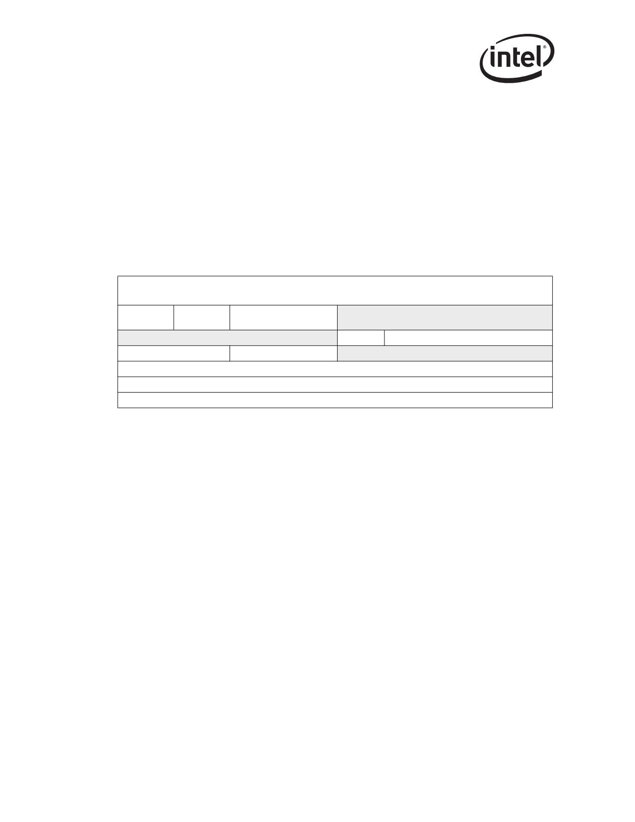
Receive and Transmit Description
Note: It is recommended that the entire header section, as described by the TCP Context Descriptor
HDRLEN field, be coalesced into a single buffer and described using a single data descriptor.
3.5.7
IP and TCP/UDP Headers
This section outlines the format and content for the IP, TCP and UDP headers. The Ethernet
controller requires baseline information from the software device driver in order to construct the
appropriate header information during the segmentation process.
Header fields that are modified by the Ethernet controller are highlighted in the figures that follow.
The IPv4 header is first shown in the traditional (RFC 791) representation, and because byte and bit
ordering is confusing in that representation, the IP header is also shown in little-endian format. The
actual data is fetched from memory in little-endian format.
1
2
3
0
1
2
3
4
5
6
7
8
9
0
1 2
3
4
5
6
7
8
9
0
1
2
3 4
5
6 7
8
9
0
1
IP Hdr
Version
TYPE of service
Total length
Length
Identification
Flags
Fragment Offset
Time to Live
Layer 4 Protocol ID
Header Checksum
Source Address
Destination Address
Options
Figure 3-8. IPv4 Header (Traditional Representation)
60
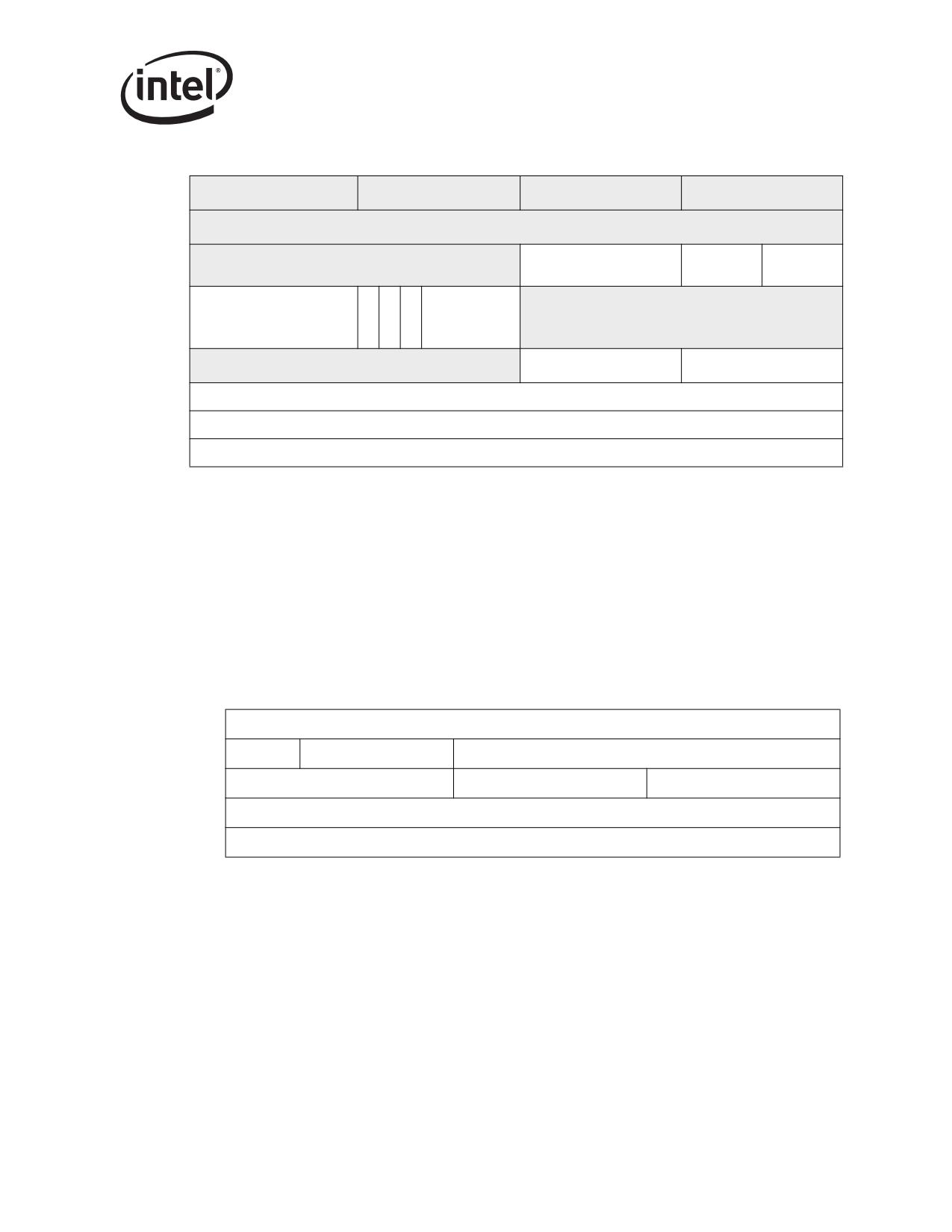
Receive and Transmit Description
Byte 3
Byte 2
Byte 1
Byte 0
7
6
5
4
3
2
1
0
7
6
5
4
3
2
1
0
7
6
5
4
3
2
1
0
7
6
5
4
3
2
1
0
IP Hdr
LSB
Total length
MSB
TYPE of service
Version
Length
R
N
M
Fragment
Fragment Offset Low
E
LSB
Identification
MSB
F
F
Offset High
S
Header Checksum
Layer 4 Protocol ID
Time to Live
Source Address
Destination Address
Options
Figure 3-9. IPv4 Header (Little-Endian Order)
Flags Field Definition:
The Flags field is defined below. Note that hardware does not evaluate or change these bits.
• MF
More Fragments
• NF
No Fragments
• Reserved
Note: The IPv6 header is first shown in the traditional (RFC 2460), big-endian representation. The actual
data is fetched from memory in little-endian format.
1
2
3
0
1
2
3
4
5
6
7
8
9
0
1
2
3
4
5
6
7
8
9
0
1
2
3
4
5
6
7
8
9
0
1
Version
Traffic Class
Flow Label
Payload Length
Next Header
Hop Limit
Source Address
Destination Address
Figure 3-10. IPv6 TCP Header (Traditional Representation)
A TCP or UDP frame uses a 16 bit wide one’s complement checksum. The checksum word is
computed on the outgoing TCP or UDP header and payload, and on the Pseudo Header. Details on
checksum computations are provided in Section 3.5. TCP requires the use of checksum, where it is
optional for UDP.
61
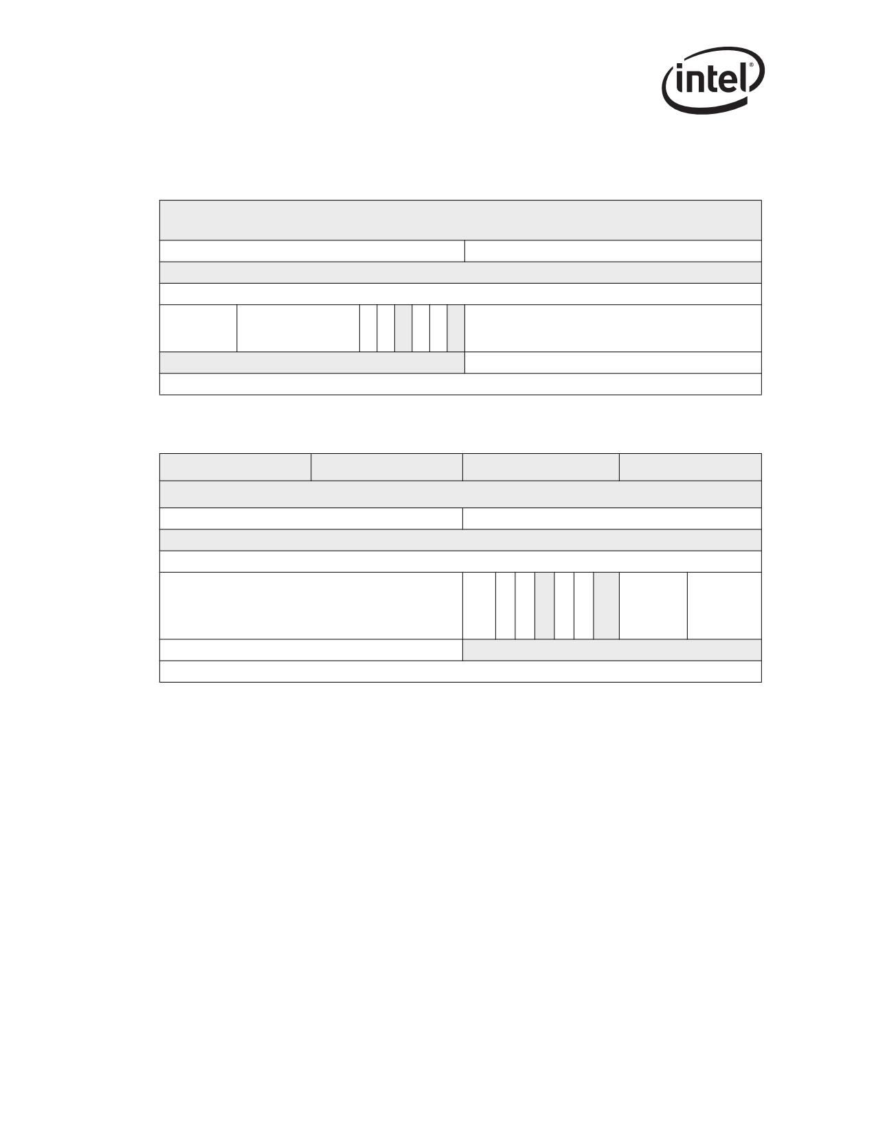
Receive and Transmit Description
The TCP header is first shown in the traditional (RFC 793) representation. Because byte and bit
ordering is confusing in that representation, the TCP header is also shown in little-endian format.
The actual data is fetched from memory in little-endian format.
1
2
3
0
1
2
3
4
5
6
7
8
9
0
1
2
3
4
5
6
7
8
9
0
1
2
3
4
5
6 7
8
9
0
1
Source Port
Destination Port
Sequence Number
Acknowledgement Number
U
A
P
R
S
F
TCP Header
Reserved
R
C
S
S
Y
I
Window
Length
G
K
H
T
N
N
Checksum
Urgent Pointer
Options
Figure 3-11. TCP Header (Traditional Representation)
Byte3
Byte2
Byte1
Byte0
7
6
5
4
3
2
1
0
7
6
5
4
3
2
1
0
7 6
5
4
3
2
1
0
7
6
5
4
3
2
1
0
Destination Port
Source Port
LSB
Sequence Number
MSB
Acknowledgement Number
FI
TCP
Reserved
U
A
P
R
S
R E
Window
R
C
S
S
Y
N
Header
S
G
K
H
T
N
Length
Urgent Pointer
Checksum
Options
Figure 3-12. TCP Header (Little-Endian)
The TCP header is always a multiple of 32 bit words. TCP options may occupy space at the end of
the TCP header and are a multiple of 8 bits in length. All options are included in the checksum.
The checksum also covers a 96-bit pseudo header conceptually prefixed to the TCP Header (see
Figure 3-13 and Figure 3-14). The IPv4 pseudo header contains the IPv4 Source Address, the IPv4
Destination Address, the IPv4 Protocol field, and TCP Length. The IPv6 pseudo header contains
the IPv6 Source Address, the IPv6 Destination Address, the IPv6 Payload Length, and the IPv6
Next Header field. Software pre-calculates the partial pseudo header sum, which includes IPv4 SA,
DA and protocol types, but not the TCP length, and stores this value into the TCP checksum field
of the packet.
The Protocol ID field should always be added the least significant byte (LSB) of the 16 bit pseudo
header sum, where the most significant byte (MSB) of the 16 bit sum is the byte that corresponds to
the first checksum byte out on the wire.
The TCP Length field is the TCP Header Length including option fields plus the data length in
bytes, which is calculated by hardware on a frame by frame basis. The TCP Length does not count
the 12 bytes of the pseudo header. The TCP length of the packet is determined by hardware as:
62
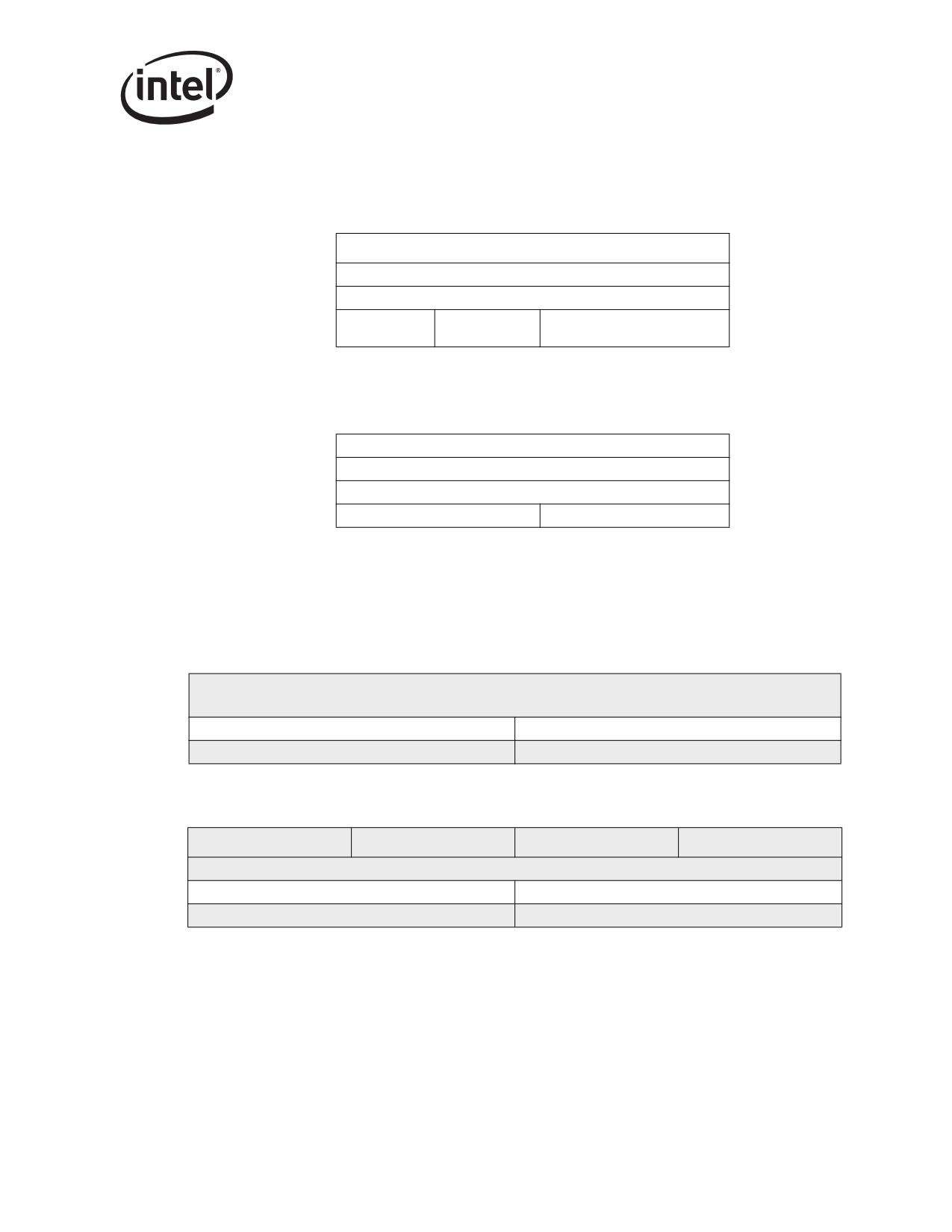
Receive and Transmit Description
TCP Length = Payload + HDRLEN - TUCSS
“Payload” is normally MSS except for the last packet where it represents the remainder of the
payload.
0
31
IP Source Address
IP Destination Address
Layer 4 Protocol
Zero
TCP Length
ID
Figure 3-13. TCP Pseudo Header Content (Traditional Representation)
IP Source Address
IP Destination Address
Upper Layer Packet Length
Zero
Next Header
Figure 3-14. TCP PseudoHeader Content for IPv6
Note: The IP Destination address is the final destination of the packet. Therefore, if a routing header is
used, the last address in the route list is used in this calculation. The upper-layer packet length is
the length of the TCP header and the TCP payload.
The UDP header is always 8 bytes in size with no options.
1
2
3
0
1
2
3
4
5
6
7
8
9
0
1 2
3
4
5
6
7
8
9
0
1
2
3
4
5
6 7
8
9
0
1
Source Port
Destination Port
Length
Checksum
Figure 3-15. UDP Header (Traditional Representation)
Byte3
Byte2
Byte1
Byte0
0
1
2
3
4
5
6
7
0
1
2
3
4
5
6
7
0
1
2
3
4
5
6
7
0
1
2
3
4
5
6
7
Destination Port
Source Port
Checksum
Length
Figure 3-16. UDP Header (Little-Endian Order)
63

Receive and Transmit Description
UDP pseudo header has the same format as the TCP pseudo header. The IPv4 pseudo header
conceptually prefixed to the UDP header contains the IPv4 source address, the IPv4 destination
address, the IPv4 protocol field, and the UDP length (same as the TCP Length discussed above).
The IPv6 pseudo header for UDP is the same as the IPv6 pseudo header for TCP. This checksum
procedure is the same as is used in TCP.
IP Source Address
IP Destination Address
Layer 4
Zero
UDP Length
Protocol ID
Figure 3-17. UDP Pseudo Header Diagram for IPv4
IP Source Address
IP Destination Address
Upper Layer Packet Length
Zero
Next Header
Figure 3-18. UDP PseudoHeader Diagram for IPv6
Note: The IP Destination Address is the final destination of the packet. Therefore, if a routing header is
used, the last address in the route list is used in this calculation. The upper-layer packet length is
the length of the UDP header and UDP payload.
Unlike the TCP checksum, the UDP checksum is optional. Software must set the TXSM bit in the
TCP/IP Context Transmit Descriptor to indicate that a UDP checksum should be inserted.
Hardware does not overwrite the UDP checksum unless the TXSM bit is set.
3.5.8
Transmit Checksum Offloading with TCP Segmentation
The Ethernet controller supports checksum off-loading as a component of the TCP Segmentation
offload feature and as a standalone capability. Section 3.5.8 describes the interface for controlling
the checksum off-loading feature. This section describes the feature as it relates to TCP
Segmentation.
The Ethernet controller supports IP and TCP/UDP header options in the checksum computation for
packets that are derived from the TCP Segmentation feature. The Ethernet controller is capable of
computing one level of IP header checksum and one TCP/UDP header and payload checksum. In
case of multiple IP headers, the driver has to compute all but one IP header checksum. The
Ethernet controller calculates checksums on the fly on a frame by frame basis and inserts the result
in the IP/TCP/UDP headers of each frame. TCP and UDP checksum are a result of performing the
checksum on all bytes of the payload and the pseudo header.
64
Receive and Transmit Description
Three specific types of checksum are supported by the hardware in the context of the TCP
Segmentation offload feature:
• IPv4 checksum (IPv6 does not have a checksum)
• TCP checksum
• UDP checksum
Each packet that is sent via the TCP segmentation offload feature optionally includes the IPv4
checksum and either the TCP or UDP checksum.
All checksum calculations use a 16-bit wide one’s complement checksum. The checksum word is
calculated on the outgoing data. The checksum field is written with the 16 bit one’s complement of
the one’s complement sum of all 16-bit words in the range of CSS to CSE, including the checksum
field itself.
3.5.9
IP/TCP/UDP Header Updating
IP/TCP/UDP header is updated for each outgoing frame based on the IP/TCP header prototype
which hardware transfers from the first descriptor(s) and stores on chip. The IP/TCP/UDP headers
are fetched from host memory into an on-chip 240 byte header buffer once for each TCP
segmentation context (for performance reasons, this header is not fetched again for each additional
packet that is derived from the TCP segmentation process). The checksum fields and other header
information are later updated on a frame by frame basis. The updating process is performed
concurrently with the packet data fetch.
The following sections define which fields are modified by hardware during the TCP Segmentation
process by the Ethernet controller. Figure 3-19 illustrates the overall data flow.
65
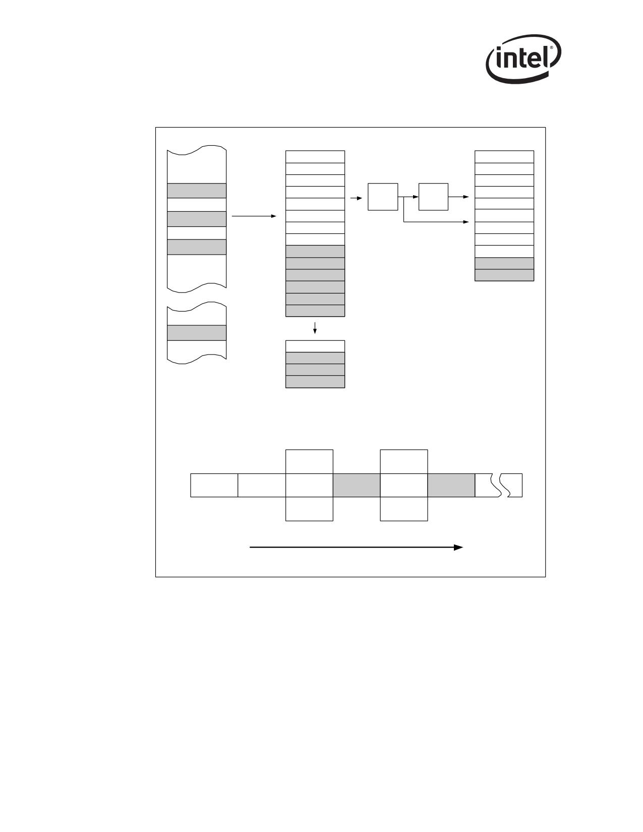
Receive and Transmit Description
PCI FIFO
IP/TCP Header
Header
Checksum
Update
Calculation
Packet Data
Packet Data
TX Packet FIFO
Packet Data
HOST Memory
IP/TCP Header Buf f er
TCP Segmentation Data Flow
Header processing
Header processing
Data Fetch Pause
Data Fetch Pause
IP/TCP Header
Data Fetch
Descriptors fetch
Packet Data Fetch
Checksum Header
Checksum Header
Prototy pe f etch
resume
Insertion
Insertion
Checksum
Checksum
Calculations
Calculations
Time
Events Scheduling
Figure 3-19. Overall Data Flow
66
Receive and Transmit Description
3.5.9.1
TCP/IP/UDP Header for the First Frame
The hardware makes the following changes to the headers of the first packet that is derived from
each TCP segmentation context.
• IPv4 Header
- IP Total Length = MSS + HDRLEN - IPCSS
- IP Checksum
- IPv6 Header
- Payload Length = MSS + HDRLEN - IPCSS
• TCP Header
- Sequence Number: The value is the Sequence Number of the first TCP byte in this frame.
- If FIN flag = 1b, it is cleared in the first frame.
- If PSH flag =1b, it is cleared in the first frame.
- TCP Checksum
• UDP Header
- UDP length: MSS + HDRLEN - TUCSS
- UDP Checksum
3.5.9.2
TCP/IP/UDP Header for the Subsequent Frames
The hardware makes the following changes to the headers for subsequent packets that are derived
as part of a TCP segmentation context:
Note:
Number of bytes left for transmission = PAYLEN - (N * MSS). Where N is the number of frames
that have been transmitted.
• IPv4 Header
- IP Identification: incremented from last value (wrap around)
- IP Total Length = MSS + HDRLEN - IPCSS
- IP Checksum
• IPv6 Header
• Payload Length = MSS + HRDLEN - IPCSS
• TCP Header
- Sequence Number update: Add previous TCP payload size to the previous sequence
number value. This is equivalent to adding the MSS to the previous sequence number.
- If FIN flag = 1b, it is cleared in these frames.
- If PSH flag =1b, it is cleared in these frames.
- TCP Checksum
• UDP Header
- UDP Length: MSS + HDRLEN - TUCSS
- UDP Checksum
67
//////////////////////////////////////////