SYSMAC CPM1/CPM1A/CPM2A/CPM2C/SRM1(–V2). Programmable Controllers (2001) - page 2
CPM1/CPM1A Interrupt Functions
Section
2-3
Use the following steps to program input interrupts using the Counter Mode.
1, 2, 3...
1. Write the set values for counter operation to the SR words shown in the fol-
lowing table. The set values are written between 0000 and FFFF (0 to
65,535). A value of 0000 will disable the count operation until a new value is
set and step 2, below, is repeated.
Interrupt
Word
Input interrupt 0
SR 240
Input interrupt 1
SR 241
Input interrupt 2
SR 242
Input interrupt 3
SR 243
The SR words used in the Counter Mode (SR 240 to SR 243) contain hexa-
decimal data, not BCD. If the Counter Mode is not used, these words can be
used as work bits.
Note These SR words are cleared at the beginning of operation, and must
be written from the program.
2. With the INT(89) instruction, refresh the Counter Mode set value and enable
interrupts.
(@)INT(89)
If D bits 0 to 3, which correspond to input interrupts 0 to 3,
are set to “0,” then the set value will be refreshed and inter-
003
rupts will be permitted.
000
0: Counter mode set value refreshed and mask cleared.
D
1: Not refreshed.
Be sure to set the corresponding bit to 1 if an input interrupt isn’t being con-
trolled.
The input interrupt for which the set value is refreshed will be enabled in Counter
Mode. When the counter reaches the set value, an interrupt will occur, the count-
er will be reset, and counting/interrupts will continue until the counter is stopped.
Note
1. If the INT(89) instruction is used during counting, the present value (PV) will
return to the set value (SV). You must, therefore, use the differentiated form
of the instruction or an interrupt may never occur.
2. The set value will be set when the INT(89) instruction is executed. If inter-
rupts are already in operation, then the set value will not be changed just by
changing the content of SR 240 to SR 243, i.e., if the contents are changed,
the set value must be refreshed by executing the INT(89) instruction again.
Interrupts can be masked using the same process used with the Input Interrupt
Mode, but if the masked interrupts are cleared using the same process, the inter-
rupts will operate in Input Interrupt Mode, not Counter Mode.
Interrupt signals received for masked interrupts can also be cleared using the
same process as for the Input Interrupt Mode.
Counter PV in Counter Mode
When input interrupts are used in Counter Mode, the counter PV will be stored in
the SR word corresponding to input interrupts 0 to 3. Values are 0000 to FFFE (0
to 65,534) and will equal the counter PV minus one.
Interrupt
Word
Input interrupt 0
SR 244
Input interrupt 1
SR 245
Input interrupt 2
SR 246
Input interrupt 3
SR 247
Example: The present value for an interrupt whose set value is 000A will be re-
corded as 0009 immediately after INT(89) is executed.
Note
Even if input interrupts are not used in Counter Mode, these SR bits cannot be
used as work bits.
78
CPM1/CPM1A Interrupt Functions
Section
2-3
Program Example
When input 00003 (interrupt no. 0) goes ON 10 times, operation moves immedi-
ately to the interrupt program with subroutine number 000. The following table
shows where the counters‘ set values and present values -1 are stored. Inputs
for DM 6628 have been set to 0001.
Interrupt
Word containing
Word containing
SV
PV-1
Input 00003 (input interrupt 0)
SR 240
SR 244
Input 00004 (input interrupt 1)
SR 241
SR 245
Input 00005 (input interrupt 2)
SR 242
SR 246
Input 00006 (input interrupt 3)
SR 243
SR 247
25315 First Cycle Flag
ON for 1 cycle
MOV(21)
#000A
Sets the SV to 10. (0000 to FFFF)
240
Word containing the SV (SR 240)
@INT(89)
003
Refresh counter SVs.
000
#000E
Refreshes the SV of 00003 (interrupt input 0) only.
SBN(92)
000
Interrupt program
RET(93)
2-3-3
Masking All Interrupts
All interrupts, including input interrupts, interval timer interrupts, and high-speed
counter interrupts, can be masked and unmasked as a group by means of the
INT(89) instruction. The mask is in addition to any masks on the individual types
of interrupts. Furthermore, clearing the masks for all interrupts does not clear the
masks on the individual types of interrupts, but restores them to the masked
conditions that existed before INT(89) was executed to mask them as a group.
Do not use INT(89) to mask interrupts unless it is necessary to temporarily mask
all interrupts and always use INT(89) instructions in pairs to do so, using the first
INT(89) instruction to mask and the second one to unmask interrupts.
INT(89) cannot be used to mask and unmask all interrupts from within interrupt
routines.
Masking Interrupts
Use the INT(89) instruction to disable all interrupts.
(@)INT(89)
100
000
000
If an interrupt is generated while interrupts are masked, interrupt processing will
not be executed but the interrupt will be recorded for the input, interval timer, and
high-speed counter interrupts. The interrupts will then be serviced as soon as
interrupts are unmasked.
79
CPM1/CPM1A Interrupt Functions
Section
2-3
Unmasking Interrupts
Use the INT(89) instruction to unmask interrupts as follows:
(@)INT(89)
200
000
000
2-3-4
Interval Timer Interrupts
The CPM1/CPM1A is equipped with one interval timer. When the interval timer
times out, the main program is interrupted and the interrupt program is executed
immediately, regardless of the point in the cycle.
There are two modes for interval timer operation, the One-shot Mode, in which
only one interrupt will be executed when time expires, and the Scheduled Inter-
rupt Mode in which the interrupt is repeated at a fixed interval.
The interval timer’s set value can be set anywhere from 0.5 to 319968 ms, in
units of 0.1 ms.
Operation
Use the following instruction to activate and control the interval timer.
Starting Up in One-Shot Mode
Use the STIM(69) instruction to start the interval timer in the one-shot mode.
(@)STIM(69)
C1: Interval timer, one-shot mode (000)
C1
C2: Timer set value (first word address)
C2
C3: Subroutine no. (4 digits BCD): 0000 to 0049
C3
1, 2, 3...
1. When C2 is entered as a word address:
C2: Decrementing counter set value (4 digits BCD): 0000 to 9999
C2 + 1: Decrementing time interval (4 digits BCD; unit: 0.1 ms): 0005 to 0320
(0.5 ms to 32 ms)
Each time that the interval specified in word C2 + 1 elapses, the decrement-
ing counter will decrement the present value by one. When the PV reaches
0, the designated subroutine will be called just once and the timer will stop.
The time from when the STIM(69) instruction is executed until time elapses
is calculated as follows:
(Content of C2) × (Content of C2 + 1) × 0.1 ms = (0.5 to 319,968 ms)
2. When C2 is entered as a constant:
The set value of the decrementing counter will equal the specified constant
(in ms) and the decrementing time interval will be 10 (1 ms).
Starting Up in Scheduled Interrupt Mode
Use the STIM(69) instruction to start the interval timer in the scheduled interrupt
mode.
(@)STIM(69)
C1: Interval timer, scheduled interrupt mode (003)
C1
C2: Timer set value (leading word no.)
C2
C3: Subroutine no. (4 digits BCD): 0000 to 0049
C3
1, 2, 3...
1. When C2 is entered as a word address:
C2: Decrementing counter set value (4 digits BCD): 0000 to 9999
C2 + 1: Decrementing time interval (4 digits BCD; unit: 0.1 ms): 0005 to 0320
(0.5 ms to 32 ms)
The meanings of the settings are the same as for the one-shot mode, but in
the scheduled interrupt mode the timer PV will be reset to the set value and
decrementing will begin again after the subroutine has been called. In the
scheduled interrupt mode, interrupts will continue to be repeated at fixed in-
tervals until the operation is stopped.
80
CPM1/CPM1A Interrupt Functions
Section
2-3
2. When C2 is entered as a constant:
The settings are the same as for the one-shot mode, but interrupts will con-
tinue to be repeated at fixed intervals until the operation is stopped.
Reading the Timer’s Elapsed Time
Use the STIM(69) instruction to read the timer’s elapsed time.
(@)STIM(69)
C1: Read elapsed time (006)
C1
C2: Leading word of parameter 1
C2
C3: Parameter 2
C3
C2: Number of times the decrementing counter has ben decremented (4 digits
BCD)
C2 + 1: Decrementing counter time interval (4 digits BCD; unit: 0.1 ms)
C3: Elapsed time from previous decrement (4 digits BCD; unit: 0.1 ms)
The time from when the interval timer is started until the execution of this instruc-
tion is calculated as follows:
{(Content of C2) × (Content of C2+1) + (Content of C3)} × 0.1 ms
If the specified interval timer is stopped, then “0000” will be stored.
Stopping the Timer
Use the STIM(69) instruction to stop the interval timer. The interval timer will be
stopped.
(@)STIM(69)
C1
C1: Stop interval timer (010)
000
000
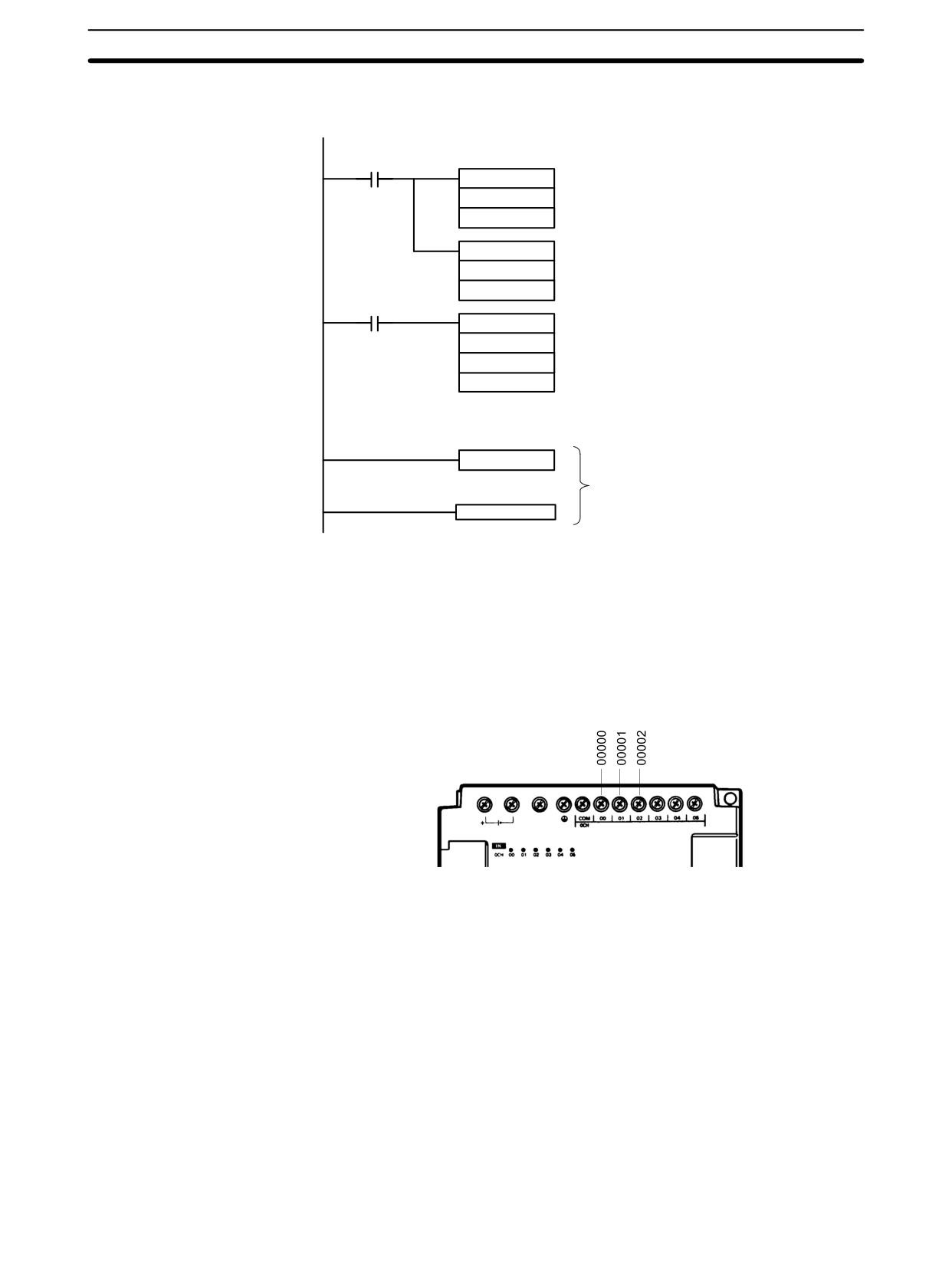
Application Example
In this example, an interrupt is generated 2.4 ms (0.6 ms × 4) after input 00005
(One-shot Mode)
goes ON; the interrupt executes interrupt subroutine number 23.
25315 First Cycle Flag
ON for 1 cycle
MOV(21)
#0004
Sets the decrementing counter‘s set value to 4.
DM 0010
(BCD: 0000 to 9999)
MOV(21)
#0006
Sets the decrementing time interval to 0.6 ms.
DM 0011
(BCD: 0005 to 0320)
00005
@STIM(69)
000
Starts the interval timer in one-shot mode.
DM 0010
Specifies the first word containing the set value.
#0023
Specifies the subroutine number (23).
SBN(92)
023
Interrupt program
RET(93)
81
CPM1/CPM1A Interrupt Functions
Section
2-3
Application Example
In this example, an interrupt is generated every 4.0 ms (1.0 ms × 4) after input
(Scheduled Interrupt Mode)
00005 goes ON; the interrupts execute interrupt subroutine number 23.
25315 First Cycle Flag
ON for 1 cycle
MOV(21)
#0004
Sets the decrementing counter‘s set value to 4.
DM 0010
(BCD: 0000 to 9999)
MOV(21)
#0010
Sets the decrementing time interval to 1.0 ms.
DM 0011
(BCD: 0005 to 0320)
00005
@STIM(69)
003
Starts the interval timer in scheduled interrupt mode.
DM 0010
Specifies the first word containing the set value.
#0023
Specifies the subroutine number (23).
SBN(92)
023
Interrupt program
RET(93)
2-3-5
High-speed Counter Interrupts
CPM1/CPM1A PCs have a high-speed counter function that can be used in in-
crementing mode or up/down mode. The high-speed counter can be combined
with input interrupts to perform target value control or zone comparison control
that isn’t affected by the PC’s cycle time.
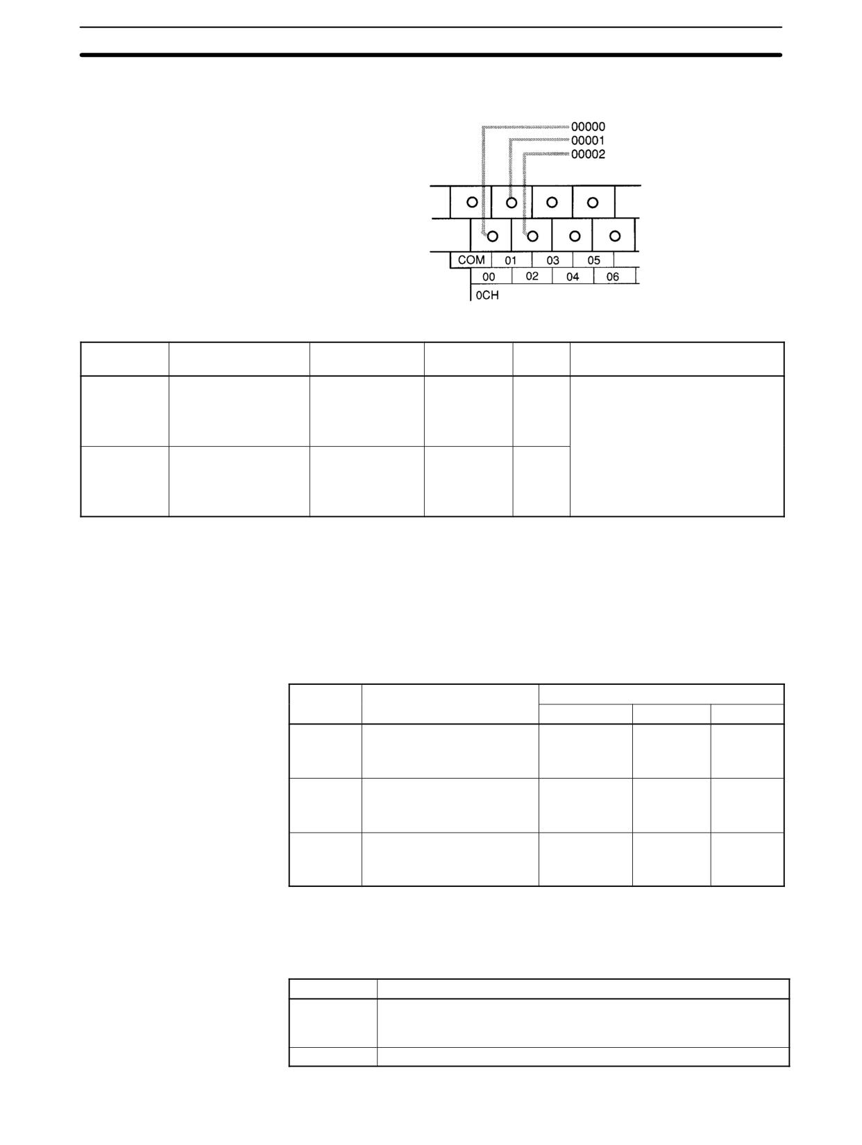
High-speed counter signals can be input to CPU bits 00000 through 00002.
CPM1 PCs
NC
24VDC
82
CPM1/CPM1A Interrupt Functions
Section
2-3
CPM1A PCs
Mode
Input functions
Input method
Count
Count
Control methods
frequency
range
Up/Down
00000: Phase-A input
Phase-difference,
2.5 kHz max.
-32767
Target value control:
00001: Phase-B input
4× inputs
to
Up to 16 target values and
00002: Phase-Z input
32767
interrupt subroutine numbers can
be registered.
Z
ison control
one compar
:
Incrementing
00000: Count input
Individual inputs
5.0 kHz max.
0
Up to 8 sets of upper limit values,
00001: See note.
to
lower limit values, and interrupt
00002: Reset input
65535
subroutine numbers can be
registered.
Note
In incrementing mode, input 00001 can be used as a regular input. When the
reset method is used for the software reset, input 00002 can be used as a regular
input. Also, even when used for the phase-Z signal and software reset, the input
status is reflected inn 00002 of the I/O memory.
High-speed Counter Settings
The following settings must be made in DM
6642 when using the
CPM1/CPM1A’s high-speed counter function.
DM 6642
Function
Settings
Bits
Incrementing
Up/Down
Not used
00 to 03
Sets the counter mode:
4
0
0 or 4
0: Up/down
4: Incrementing
04 to 07
Sets the reset method:
0 or 1
0 or 1
0 or 1
0: Phase-Z + software reset
1: Software reset
08 to 15
Sets the counter:
01
01
00
00: Counter not being used.
01: Counter being used.
Count Range
The CPM1/CPM1A’s high-speed counter uses linear operation and the count
(present value) is stored in SR 248 and SR 249. (The upper four digits are stored
in SR 249 and the lower four digits are stored in SR 248.)
Mode
Count range
Up/Down
F003 2767 to 0003 2767 (-32,767 to 32,767)
The leftmost digit in SR 248 indicates the sign. F is negative, 0 is
positive.
Incrementing
0000 0000 to 0006 5535 (0 to 65,535)
83
CPM1/CPM1A Interrupt Functions
Section
2-3
An overflow will occur if the count exceeds the upper limit in the count range and
an underflow will occur if the count goes below the lower limit in the count range.
Error
Incrementing
Up/Down
Present
value
Overflow
Occurs when the count is
Occurs when the count is
0FFF FFFF
incremented from 65,535.
incremented from 32,767.
Underflow
---
Occurs when the count is
FFFF FFFF
decremented from -32,767.
Processing
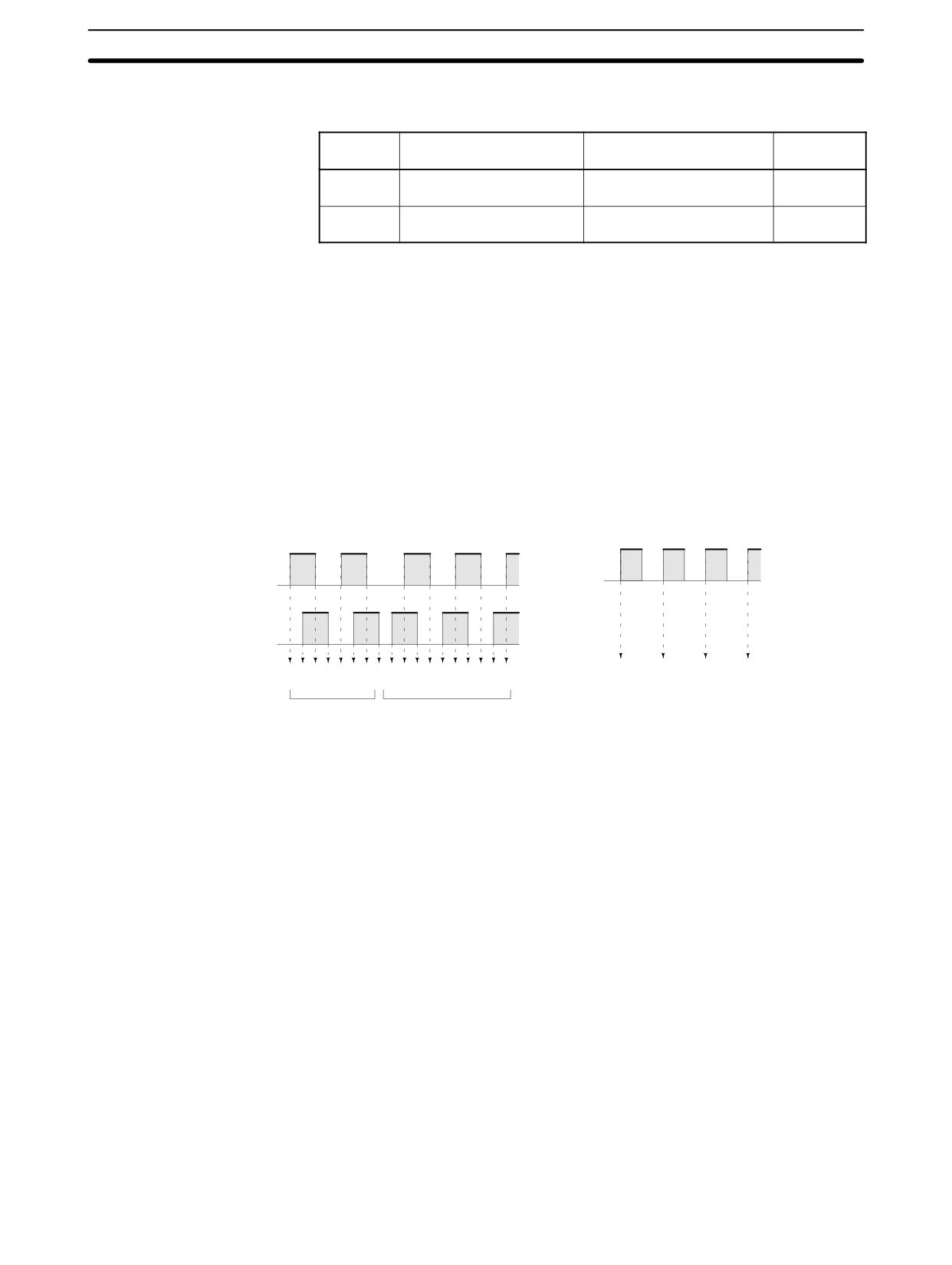
Two types of signals can be input from a pulse encoder. The count mode used for
the high-speed counter will depend on the signal type. The count mode and re-
set mode are set in DM 6642; these settings become effective when the power is
turned on or PC operation is started.
Up/Down Mode:
Phase-A difference 4× two-phase signal (phase-A and phase-B) and a
phase-Z signal are used for inputs. The count is incremented or decrem-
ented according to differences in the 2-phase signals.
Incrementing Mode:
One single-phase pulse signal and a count reset signal are used for inputs.
The count is incremented according to the single-phase signal.
Up/Down Mode
Incrementing Mode
ON
ON
Pulse
Phase A
input
OFF
OFF
ON
Phase B
OFF
Count
1
2
3
4
Count
1
2
3
4
5
6
7
8
7
6
5
4
3
2
1
0 -1 -2
Incremented
Decremented
Incremented only
Note One of the reset methods described below should always be used to reset the
counter when restarting it. The counter will be automatically reset when program
execution is started or stopped.
The following signal transitions are handled as forward (incrementing) pulses:
Phase-A leading edge to phase-B leading edge to phase-A trailing edge to
phase-B trailing edge. The following signal transitions are handled as reverse
(decrementing) pulses: Phase-B leading edge to phase-A leading edge to
phase-B trailing edge to phase-A trailing edge.
The Up/Down Mode always uses a 4× phase-difference input. The number of
counts for each encoder revolution would be 4 times the resolution of the count-
er. Select the encoder based on the countable ranges.
Reset Methods
Either of the two methods described below may be selected for resetting the PV
of the count (i.e., setting it to 0).
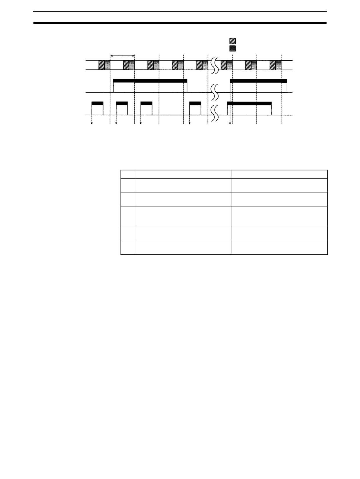
Phase-Z signal + software reset:
The PV is reset when the phase-Z signal (reset input) is turned ON while the
High-speed Counter Reset Bit (SR 25200) is ON.
Software reset:
The PV is reset when the High-speed Counter Reset Bit (SR 25200) is
turned ON.
84
CPM1/CPM1A Interrupt Functions
Section
2-3
Phase-Z Signal + Software Reset
I/O refresh
Common processing,
1 cycle
communications servicing, etc.
CPU processing
Program
Program
Program
Program
Program
Program
execution
execution
execution
execution
execution
execution
25200
(1)
(2)
(3)
(4)
(5)
Phase-Z
Not reset
Not reset Reset
Reset
Not reset
No.
Operation timing
Reset
(1)
Phase-Z signal turns ON when
Not reset.
SR 25200 turns OFF.
(2)
Phase-Z signal turns ON within one
Not reset.
cycle after SR 25200 turns ON.
(3)
Phase-Z signal turns ON after at least
Reset with phase-Z leading edge.
one cycle elapses after SR 25200
turns ON.
(4)
Phase-Z signal turns ON within one
Reset with phase-Z leading edge.
cycle after SR 25200 turns OFF.
(5)
SR 25200 turns ON when phase-Z
Not reset.
signal is ON.
Note The High-speed Counter Reset Bit (SR 25200) is refreshed once every cycle, so
in order for it to be read reliably it must be ON for at least one cycle.
The “Z” in “phase-Z” is an abbreviation for “Zero.” It is a signal that shows that the
encoder has completed one cycle.
High-speed Counter Interrupt Count
For high-speed counter 0 interrupts, a comparison table is used instead of a
“count up.” The count check can be carried out by either of the two methods de-
scribed below. In the comparison table, comparison conditions (for comparing to
the PV) and interrupt routine combinations are saved.
Target value:
A maximum of 16 comparison conditions (target values and count direc-
tions) and interrupt routine combinations are saved in the comparison table.
When the counter PV and the count direction match the comparison condi-
tions, then the specified interrupt routine is executed.
Range (zone) comparison:
Eight comparison conditions (upper and lower limits) and interrupt routine
combinations are saved in the comparison table. When the PV is greater
than or equal to the lower limit and less than or equal to the upper limit, then
the specified interrupt routine is executed.
85
CPM1/CPM1A Interrupt Functions
Section
2-3
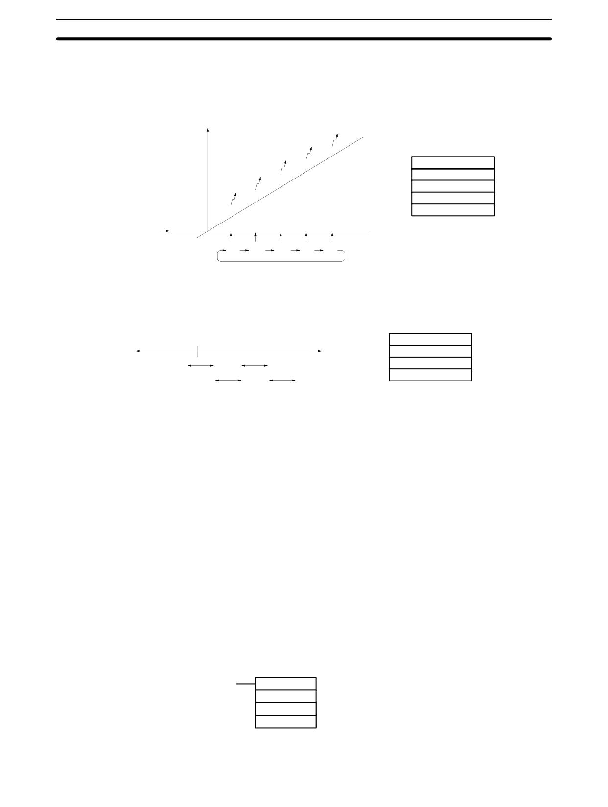
Target Value
The current count is compared to the target values in the order that target values
Comparisons
are set in the comparison table and interrupts are generated as the count equals
each target value. Once the count has equaled all of the target values in the
table, the target value is set to the first target value in the table, which is again
compared to the current counted until the two values are equal.
Count
Interrupts
Comparison Table
Target value 1
Target value 2
Target value 3
Target value 4
Target value 5
Initial value
Target value
1
2
3
4
5
The current count is compared in cyclic fashion to all of the ranges at the same
Range Comparisons
time and interrupts are generated based on the results of the comparisons.
Comparison Table
0
Rage setting 1
Count
Rage setting 2
Rage setting 3
1
3
Rage setting 4
2
4
Note When performing target value comparisons, do not repeatedly use the INI in-
struction to change the current value of the count and start the comparison op-
eration. The interrupt operation may not work correctly if the comparison opera-
tion is started immediately after changing the current value from the program.
(The comparison operation will automatically return to the first target value once
an interrupt has been generated for the last target value. Repetitious operation
is thus possible merely by changing the current value.)
Programming
Use the following steps to program the high-speed counter.
The high-speed counter begins the counting operation when the proper PC Set-
up settings are made, but comparisons will not be made with the comparison
table and interrupts will not be generated unless the CTBL(63) instruction is
executed.
The high-speed counter is reset to “0” when power is turned ON and when op-
eration begins.
The present value of high-speed counter is maintained in SR 248 and SR 249.
Controlling High-speed Counter Interrupts
1, 2, 3...
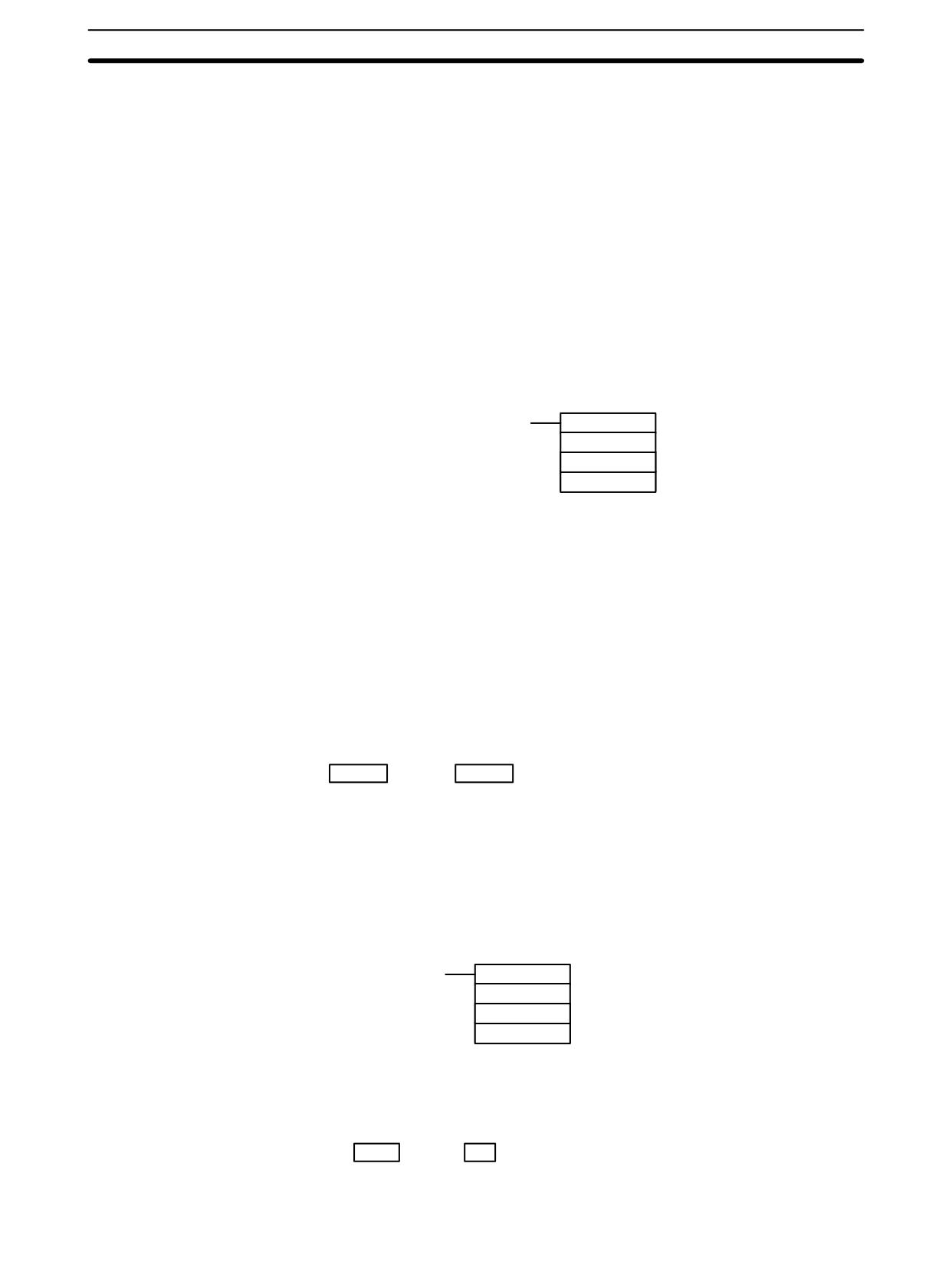
1. Use the CTBL(63) instruction to save the comparison table in the
CPM1/CPM1A and begin comparisons.
(@)CTBL(63)
P
C: (3 digits BCD)
000:
Target table set and comparison begun
C
001:
Range table set and comparison begun
TB
002:
Target table set only
003:
Range table set only
TB: Beginning word of comparison table
86
CPM1/CPM1A Interrupt Functions
Section
2-3
If C is set to 000, then comparisons will be made by the target matching
method; if 001, then they will be made by the range comparison method.
The comparison table will be saved, and, when the save operation is com-
plete, then comparisons will begin. While comparisons are being executed,
high-speed interrupts will be executed according to the comparison table.
For details on the contents of the comparison tables that are saved, refer to
the explanation of the CTBL(63) instruction in Section 7 Instruction Set.
Note The comparison results are normally stored in AR 1100 through
AR 1107 while the range comparison is being executed.
If C is set to 002, then comparisons will be made by the target matching
method; if 003, then they will be made by the range comparison method. For
either of these settings, the comparison table will be saved, but compari-
sons will not begin, and the INI(61) instruction must be used to begin com-
parisons.
2. To stop comparisons, execute the INI(61) instruction as shown below.
(@)INI(61)
000
001
000
To start comparisons again, set the second operand to “000” (execute com-
parison), and execute the INI(61) instruction.
Once a table has been saved, it will be retained in the CPM1/CPM1A during
operation (i.e., during program execution) as long as no other table is saved.
Reading the PV
There are two ways to read the PV. The first is to read it from SR 248 and
SR 249, and the second to use the PRV(62) instruction.
Reading SR 248 and SR 249
The PV of high-speed counter is stored in SR 248 and SR 249 as shown below.
The leftmost bit will be F for negative values.
Leftmost 4 digits Rightmost 4 digits
Up/Down Mode
Incrementing Mode
SR 249
SR 248
F0032767 to 00032767
00000000 to 00065535
(-32767)
Note
1. These words are refreshed only once every cycle, so there may be a differ-
ence from the actual PV.
2. When high-speed counter is not being used, the bits in these words can be
used as work bits.
Using the PRV(62) Instruction
Read the PV of the high-speed counter by using the PRV(62) instruction.
(@)PRV(62)
P1: Leading word of PV
000
000
P1
The PV of the high-speed counter is stored as shown below. The leftmost bit will
be F for negative values.
Leftmost 4 digits
Rightmost 4 digits
Up/Down Mode
Incrementing Mode
P1+1
P1
F0032767 to 00032767
00000000 to 00065535
(-32767)
87
CPM1/CPM1A Interrupt Functions
Section
2-3
The PV is read when the PRV(62) instruction is actually executed.
Changing the PV
There are two ways to change the PV of high-speed counter. The first way is to
reset it by using the reset methods. (In this case the PV is reset to 0.) The second
way is to use the INI(61) instruction.
The method using the INI(61) instruction is explained here. For an explanation of
the reset method, refer to the beginning of this description of high-speed count-
er.
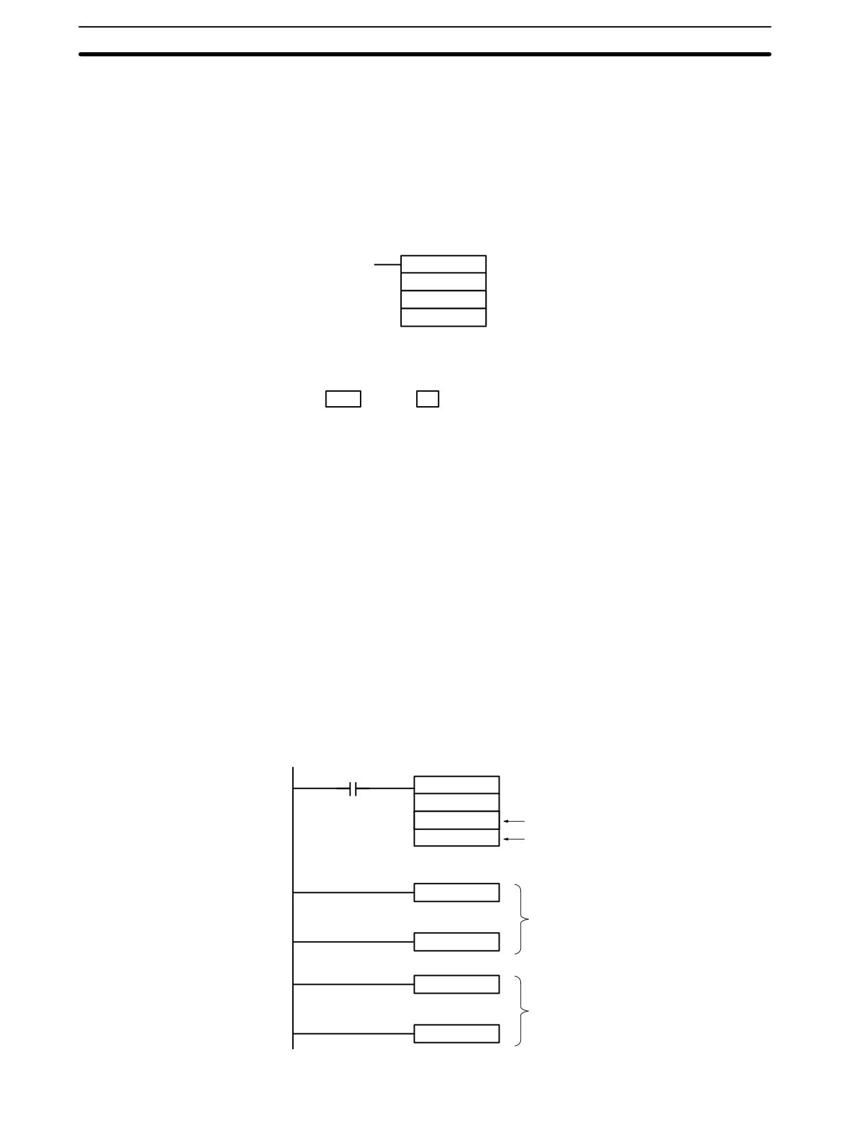
Change the timer PV by using the INI(61) instruction as shown below.
(@)INI(61)
D: Leading word for storing PV change data
000
002
D
Leftmost 4 digits Rightmost 4 digits
Up/Down Mode
Incrementing Mode
D+1
D
F0032767 to 00032767
00000000 to 00065535
To specify a negative number in up/down mode, set F in the leftmost digit.
Application Example
This example shows a program that uses the high-speed counter with single-
(Incrementing Mode)
phase inputs in the Incrementing Mode, making comparisons by means of the
target matching method.
The comparison conditions (target values and count directions) are stored in the
comparison table with the subroutine numbers. Up to 16 target values can be
stored. The corresponding subroutine is executed when the counter’s PV
matches the target value.
The following data is stored for the comparison table:
DM 0000
0002
Number of comparison conditions: 2
DM 0001
1000
Target value 1: 1000
DM 0002
0000
DM 0003
0030
Comparison 1 interrupt subroutine no.: 30
DM 0004
2000
Target value 2: 2000
DM 0005
0000
DM 0006
0031
Comparison 2 interrupt subroutine no.: 31
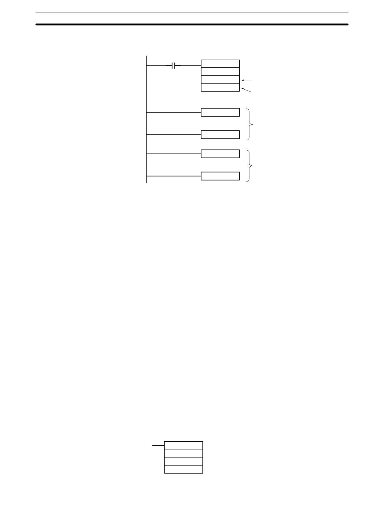
The following diagram shows the example ladder program. DM 6642 must be
set to 01j4, where j is the reset method which can be set to 0 or 1.
25315 (ON for first cycle)
CTBL(63)
000
000
Registers comparison table, target value mode
DM 0000
First word of the comparison table
SBN(92)
030
Interrupt program 30
RET(93)
SBN(92)
031
Interrupt program 31
RET(93)
88
CPM1/CPM1A Interrupt Functions
Section
2-3
Application Example
This example shows a program that uses the high-speed counter with phase-dif-
(Up/Down Mode)
ference inputs in the Up/Down Mode, making comparisons by means of the
range comparison method.
The comparison conditions (upper/lower limits of the ranges) are stored in the
comparison table with the subroutine numbers. Up to 8 separate ranges can be
defined. The corresponding subroutine is executed when the counter’s PV is
within the range.
Note Always set 8 ranges. If fewer than 8 ranges are needed, set the remaining sub-
routine numbers to FFFF. A value of FFFF indicates that no subroutine is to be
executed.
The following data is stored for the comparison table:
DM 0000
1500
DM 0001
0000
Lower limit 1: 1,500 counts
DM 0002
3000
DM 0003
0000
Upper limit 1: 3,000 counts
DM 0004
0040
Range 1 interrupt subroutine no.: 40
DM 0005
7500
DM 0006
0000
Lower limit 2: 7,500 counts
DM 0007
0000
DM 0008
0001
Upper limit 2: 10,000 counts
DM 0009
0041
Range 2 interrupt subroutine no.: 41
DM 0010
0000
DM 0011
0000
DM 0012
0000
DM 0013
0000
DM 0014
FFFF Range 3 interrupt subroutine not executed
DM 0035
0000
DM 0036
0000
DM 0037
0000
DM 0038
0000
DM 0039
FFFF Range 8 interrupt subroutine not executed
89
SRM1(-V2) Interrupt Functions
Section
2-4
The following diagram shows the example ladder program. DM 6642 must be
set to 01j0, where j is the reset method which can be set to 0 or 1.
25315 (ON for first cycle)
CTBL(63)
000
001
Registers comparison table,
DM 0000
range comparison mode
First word of the comparison table
SBN(92)
040
Interrupt program 40
RET(93)
SBN(92)
041
Interrupt program 41
RET(93)
2-3-6
Precautions on Programming Interrupts
If words in memory are being manipulated both in the main program and in an
interrupt program, the interrupts must be masked when the words are being ma-
nipulated in the main program. Refer to 2-1-3 Precautions on Programming In-
terrupts for details.
2-4
SRM1(-V2) Interrupt Functions
This section explains the settings and methods for using the SRM1(-V2) inter-
rupt functions.
2-4-1
Types of Interrupts
The SRM1(-V2) has only one type of interrupt processing, as outlined below.
Interval Timer Interrupts
Interrupt processing is executed by an interval timer with a precision of 0.1 ms.
2-4-2
Interval Timer Interrupts
The SRM1(-V2) is equipped with one interval timer. When the interval timer
times out, the main program is interrupted and the interrupt program is executed
immediately, regardless of the point in the cycle.
There are two modes for interval timer operation, the One-shot Mode, in which
only one interrupt will be executed when time expires, and the Scheduled Inter-
rupt Mode in which the interrupt is repeated at a fixed interval.
The interval timer’s set value can be set anywhere from 0.5 to 319,968 ms, in
units of 0.1 ms.
Operation
Use the following instruction to activate and control the interval timer.
Starting Up in One-Shot Mode
Use the STIM(69) instruction to start the interval timer in the one-shot mode.
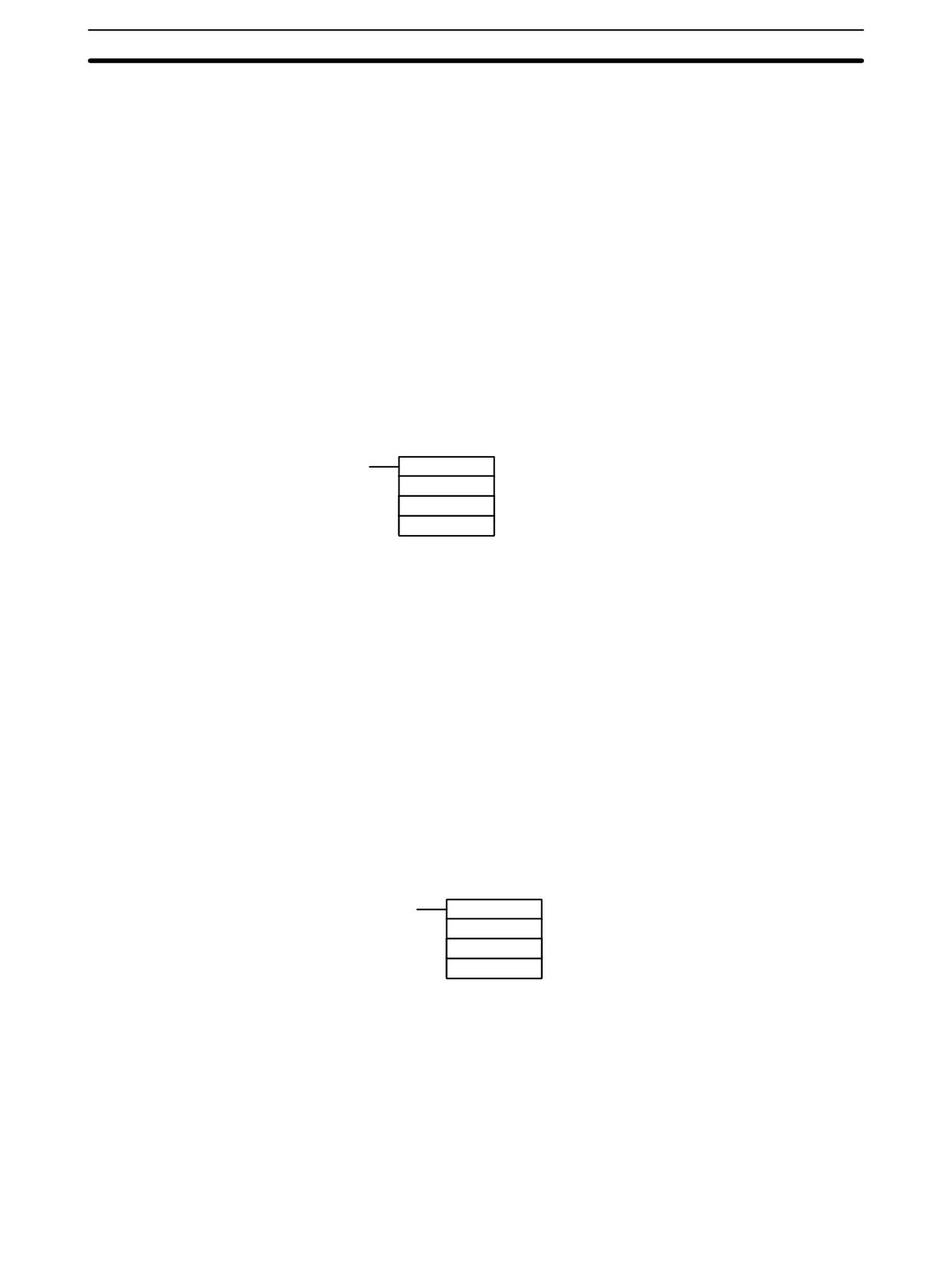
(@)STIM(69)
C1: Interval timer, one-shot mode (000)
C1
C2: Timer set value (first word address)
C2
C3: Subroutine no. (4 digits BCD): 0000 to 0049
C3
90
SRM1(-V2) Interrupt Functions
Section
2-4
1, 2, 3...
1. When C2 is entered as a word address:
C2: Decrementing counter set value (4 digits BCD): 0000 to 9999
C2 + 1: Decrementing time interval (4 digits BCD; unit: 0.1 ms): 0005 to 0320
(0.5 ms to 32 ms)
Each time that the interval specified in word C2 + 1 elapses, the decrement-
ing counter will decrement the present value by one. When the PV reaches
0, the designated subroutine will be called just once and the timer will stop.
The time from when the STIM(69) instruction is executed until time elapses
is calculated as follows:
(Content of C2) × (Content of C2 + 1) × 0.1 ms = (0.5 to 319,968 ms)
2. When C2 is entered as a constant:
The set value of the decrementing counter will equal the specified constant
(in ms) and the decrementing time interval will be 10 (1 ms).
Starting Up in Scheduled Interrupt Mode
Use the STIM(69) instruction to start the interval timer in the scheduled interrupt
mode.
(@)STIM(69)
C1: Interval timer, scheduled interrupt mode (003)
C1
C2: Timer set value (leading word no.)
C2
C3: Subroutine no. (4 digits BCD): 0000 to 0049
C3
1, 2, 3...
1. When C2 is entered as a word address:
C2: Decrementing counter set value (4 digits BCD): 0000 to 9999
C2 + 1: Decrementing time interval (4 digits BCD; unit: 0.1 ms): 0005 to 0320
(0.5 ms to 32 ms)
The meanings of the settings are the same as for the one-shot mode, but in
the scheduled interrupt mode the timer PV will be reset to the set value and
decrementing will begin again after the subroutine has been called. In the
scheduled interrupt mode, interrupts will continue to be repeated at fixed in-
tervals until the operation is stopped.
2. When C2 is entered as a constant:
The settings are the same as for the one-shot mode, but interrupts will con-
tinue to be repeated at fixed intervals until the operation is stopped.
Reading the Timer’s Elapsed Time
Use the STIM(69) instruction to read the timer’s elapsed time.
(@)STIM(69)
C1: Read elapsed time (006)
C1
C2: Leading word of parameter 1
C2
C3: Parameter 2
C3
C2: Number of times the decrementing counter has been decremented (4 digits
BCD)
C2 + 1: Decrementing counter time interval (4 digits BCD; unit: 0.1 ms)
C3: Elapsed time from previous decrement (4 digits BCD; unit: 0.1 ms)
The time from when the interval timer is started until the execution of this instruc-
tion is calculated as follows:
{(Content of C2) × (Content of C2+1) + (Content of C3)} × 0.1 ms
If the specified interval timer is stopped, then “0000” will be stored.
91
SRM1(-V2) Interrupt Functions
Section
2-4
Stopping the Timer
Use the STIM(69) instruction to stop the interval timer. The interval timer will be
stopped.
(@)STIM(69)
C1
C1: Stop interval timer (010)
000
000
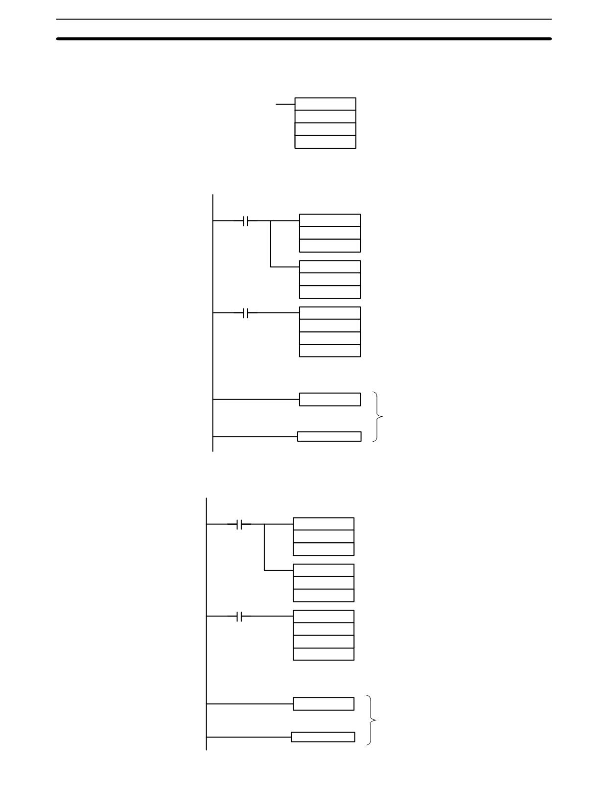
Application Example
In this example, an interrupt is generated 2.4 ms (0.6 ms × 4) after input 00005
(One-shot Mode)
goes ON; the interrupt executes interrupt subroutine number 23.
25315 First Cycle Flag
ON for 1 cycle
MOV(21)
#0004
Sets the decrementing counter‘s set value to 4.
DM 0010
(BCD: 0000 to 9999)
MOV(21)
#0006
Sets the decrementing time interval to 0.6 ms.
DM 0011
(BCD: 0005 to 0320)
00005
@STIM(69)
000
Starts the interval timer in one-shot mode.
DM 0010
Specifies the first word containing the set value.
#0023
Specifies the subroutine number (only lower by-
tes are effective).
SBN(92)
023
Interrupt program
RET(93)
Application Example
In this example, an interrupt is generated every 4.0 ms (1.0 ms × 4) after input
(Scheduled Interrupt Mode)
00005 goes ON; the interrupts execute interrupt subroutine number 23.
25315 First Cycle Flag
ON for 1 cycle
MOV(21)
#0004
Sets the decrementing counter‘s set value to 4.
DM 0010
(BCD: 0000 to 9999)
MOV(21)
#0010
Sets the decrementing time interval to 1.0 ms.
DM 0011
(BCD: 0005 to 0320)
00005
@STIM(69)
003
Starts the interval timer in scheduled interrupt mode.
DM 0010
Specifies the first word containing the set value.
#0023
Specifies the subroutine number (only the lower by-
tes are effective).
SBN(92)
023
Interrupt program
RET(93)
92
CPM2A/CPM2C Pulse Output Functions
Section
2-5
2-5
CPM2A/CPM2C Pulse Output Functions
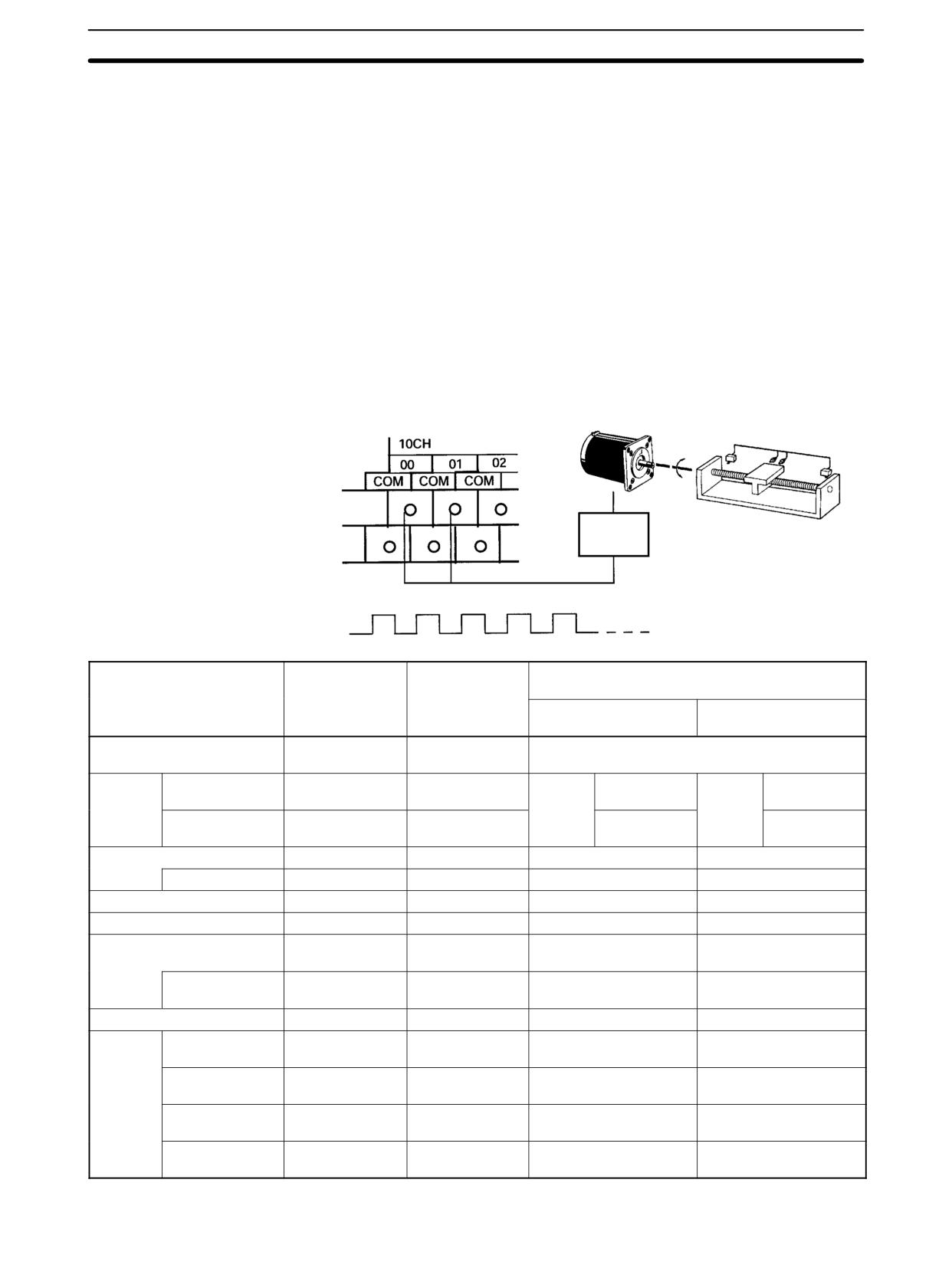
The CPM2A/CPM2C has two pulse outputs. By means of a selection in the PC
Setup, these outputs can be used as two single-phase outputs without accelera-
tion and deceleration, two variable duty ratio pulse outputs, or pulse outputs with
trapezoidal acceleration/deceleration (one pulse + direction output and one up/
down pulse output). The pulse output PV coordinate system can also be speci-
fied in the PC Setup as either relative or absolute.
There are two pulse output modes: Independent mode, in which outputs are
stopped at a preset amount of pulses, and continuous mode, in which outputs
are stopped by an instruction.
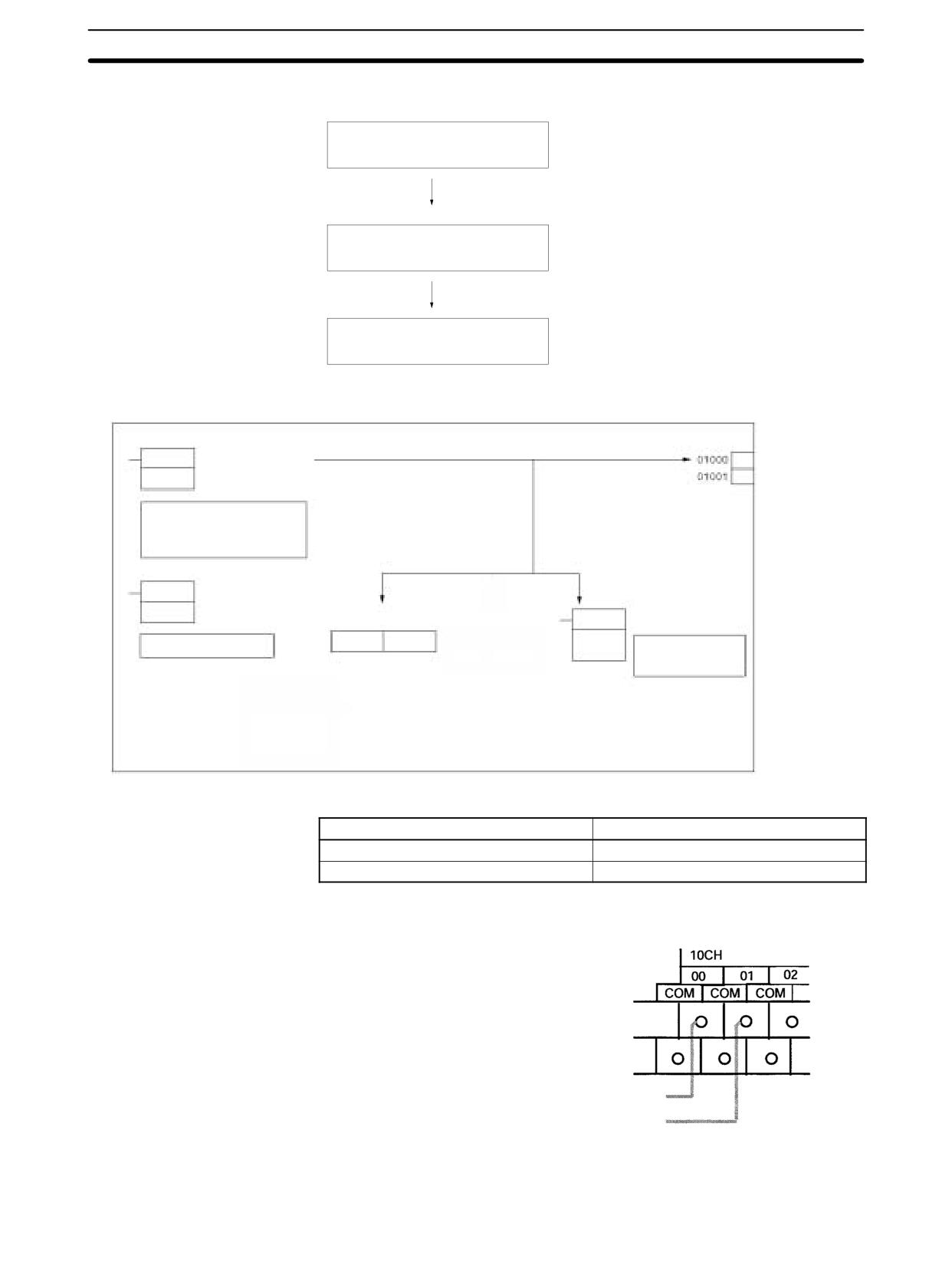
Note To use pulse outputs, it is necessary to use a CPU Unit with transistor outputs,
i.e., either a CPM2A-jjCDT-D or CPM2A-jjCDT1-D.
The following diagram shows the configuration for a CPM2A, but the configura-
tion for a CPM2C is identical.
Stepping motor
Motor
controller
Pulse outputs
Item
Single-phase
Variable duty
Single-phase pulse outputs with trapezoidal
pulse outputs
ratio pulse
acceleration/deceleration
without
outputs
Pulse + direction
Up/down pulse
accel/decel
outputs
outputs
Execution instructions
PULS(65) and
PWM(--)
PULS(65) and ACC(--)
SPED(64)
Output
01000
Pulse output 0
Pulse output 0
Pulse
Pulse output
Pulse
CW pulse
number
(See note 1.)
(See note 1.)
output 0
output 0
output
01001
Pulse output 1
Pulse output 1
Direction
CCW pulse
(See note 1.)
(See note 1.)
output
output
Output frequency range
10 Hz to 10 kHz
0.1 to 999.9 Hz
10 Hz to 10 kHz
10 Hz to 10 kHz
Pitch
10 Hz
0.1 Hz
10 Hz
10 Hz
Up/down frequency pitch
---
---
10 Hz (See note 2.)
10 Hz (See note 2.)
Start speed pitch
---
---
10 Hz
10 Hz
Output mode
Continuous,
Continuous
Continuous,
Continuous,
Independent
Independent
Independent
Number of
1 to 16777215
---
±1 to 16777215
±1 to 16777215
pulses
Duty ratio (See note 3.)
50%
0 to 100%
50%
50%
Control
Movement
Yes
No
Yes
Yes
method
specification
Accel/decel
No
No
Yes
Yes
specification
Start speed
No
No
Yes
Yes
specification
Duty
No
Yes
No
No
specification
93
CPM2A/CPM2C Pulse Output Functions
Section
2-5
Note
1. With single-phase pulse outputs, pulse outputs 0 and 1 can each be output
independently.
2. Pulse outputs can be accelerated or decelerated in units of 10 Hz every 10
ms.
3. Actual pulses are affected by the transistor output’s ON response time (20
µs max.) and OFF response time (40 µs max.).
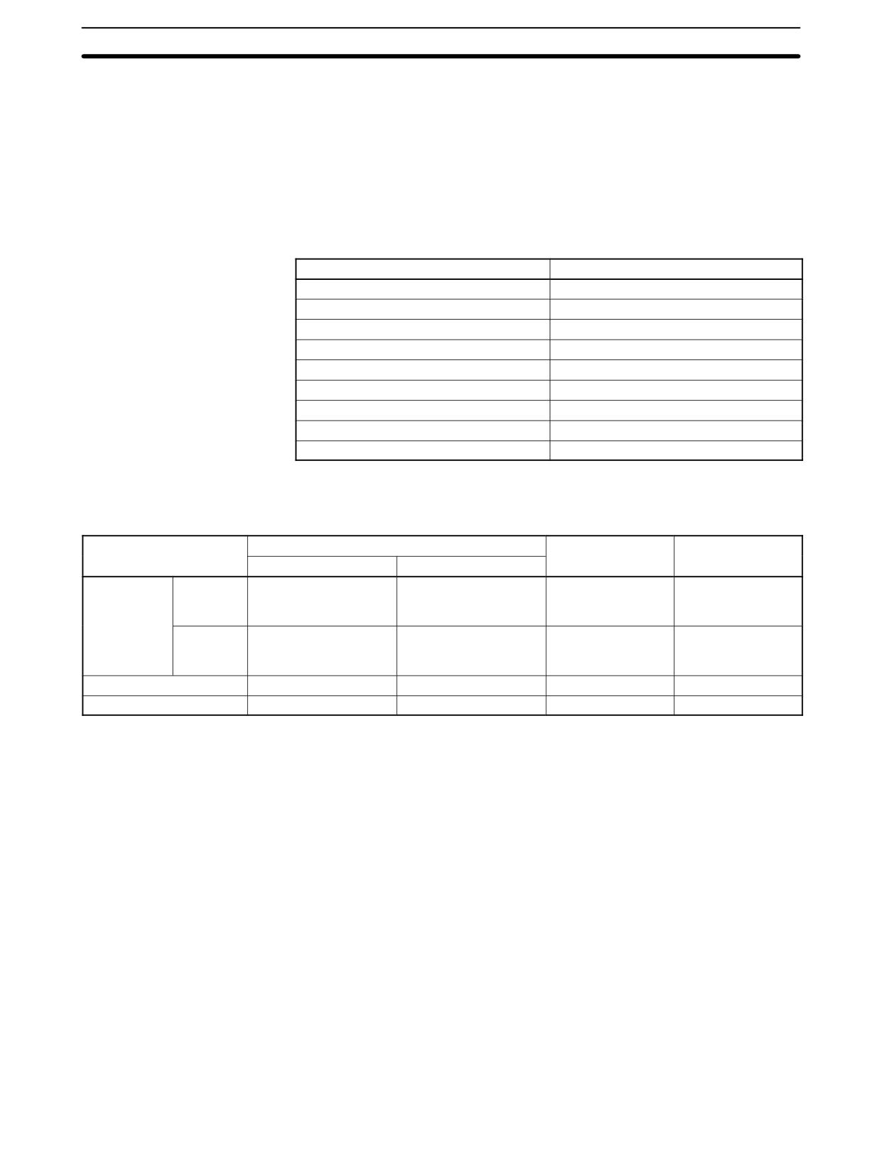
The following table shows the relationships between the high-speed counter
and the CPM2A/CPM2C’s other functions.
Interval timer interrupts
Synchronized pulse control
Cannot be used simultaneously.
Interrupt inputs
Can be used simultaneously.
Interval timer interrupts
Can be used simultaneously.
High-speed counters
Can be used simultaneously.
Interrupt inputs (counter mode)
Can be used simultaneously.
Pulse outputs
See note.
Quick-response inputs
Can be used simultaneously.
Input time constant
Can be used simultaneously.
Clock
Can be used simultaneously.
Note The number of simultaneous outputs varies according to the type of pulse out-
put, as shown in the following table.
Combination
Single-phase pulse output
Pulse + direction
Up/down pulse
output
output
Fixed duty ratio
Variable duty ratio
Single-phase
Fixed duty
Can use two points
Can use one point at a
Cannot be used.
Cannot be used.
pulse output
ratio
simultaneously
time (independently).
(independently).
Variable
Can use one point at a
Can use two points
Cannot be used.
Cannot be used.
duty ratio
time (independently).
simultaneously
(independently).
Pulse + direction output
Cannot be used.
Cannot be used.
Cannot be used.
Cannot be used.
Up/down pulse output
Cannot be used.
Cannot be used.
Cannot be used.
Cannot be used.
Up to two points can be output simultaneously with only single-phase pulse out-
puts, so two-point output is possible when fixed duty ratio and variable duty ratio
are used in combination.
Outputs are possible for only one point at a time with pulse + direction outputs
and up/down pulse outputs, so no other pulses can be output.
There are three types of pulse outputs: Single-phase pulse outputs without ac-
Types of Pulse Outputs
celeration and deceleration, variable duty ratio pulse outputs, and single-phase
pulse outputs with trapezoidal acceleration and deceleration.
Single-phase Pulse Outputs Without Acceleration and Deceleration
• Frequency:
10 Hz to 10 kHz (Set in units of 10 Hz.)
• Output destination:
Output number 01000 (Word 010, bit 00)
Output number 01001 (Word 010, bit 01)
(Pulses can be output simultaneously and indepen-
dently from two points.
• Output mode:
Continuous or Independent
• Number of pulses:
1 to 16,777,215
94
CPM2A/CPM2C Pulse Output Functions
Section
2-5
• Instructions:
PULS(65) and SPED(64)
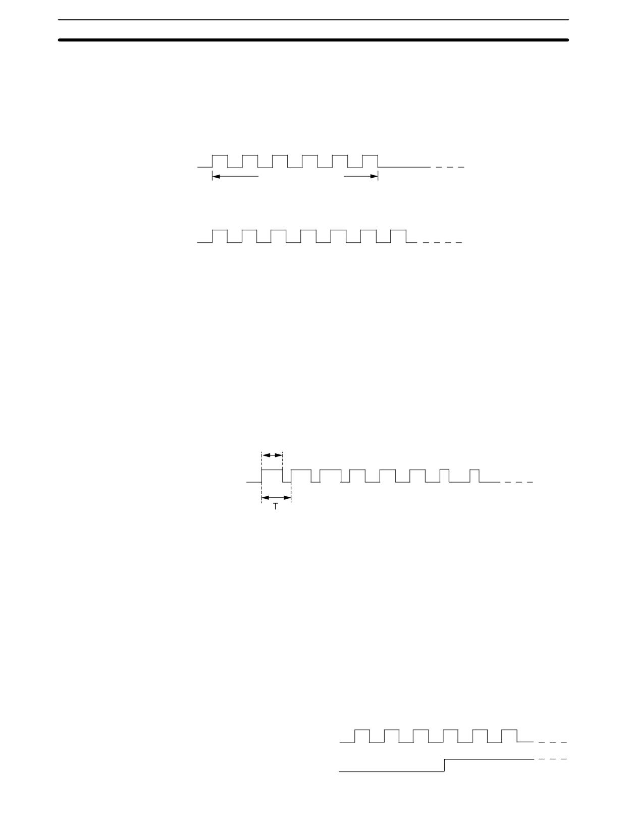
• With PULS(65), the number of pulses is set for each point (in independent
mode only).
• With SPED(64), the output mode and target frequency are set for each
point, and pulses are output.
Instruction execution: PULS(65) + SPED(64) (Independent mode)
Independent mode
Number of set pulses
The output is stopped automatically when the set number of pulses has been output.
Instruction execution: SPED(64) (Continuous mode)
Continuous mode
Pulses continue to be output at the set frequency until stopped by the instruction.
Variable Duty Ratio Pulse Outputs
• Duty ratio:
0% to 100% (Set in units of 1%.)
• Frequency:
0.1 to 999.9 Hz (Set in units of 0.1 Hz.)
• Output destination:
Output number 01000 (Word 010, bit 00)
Output number 01001 (Word 010, bit 01)
(Pulses can be output simultaneously and indepen-
dently from two points.)
• Output mode:
Continuous
• Instruction:
PWM(--)
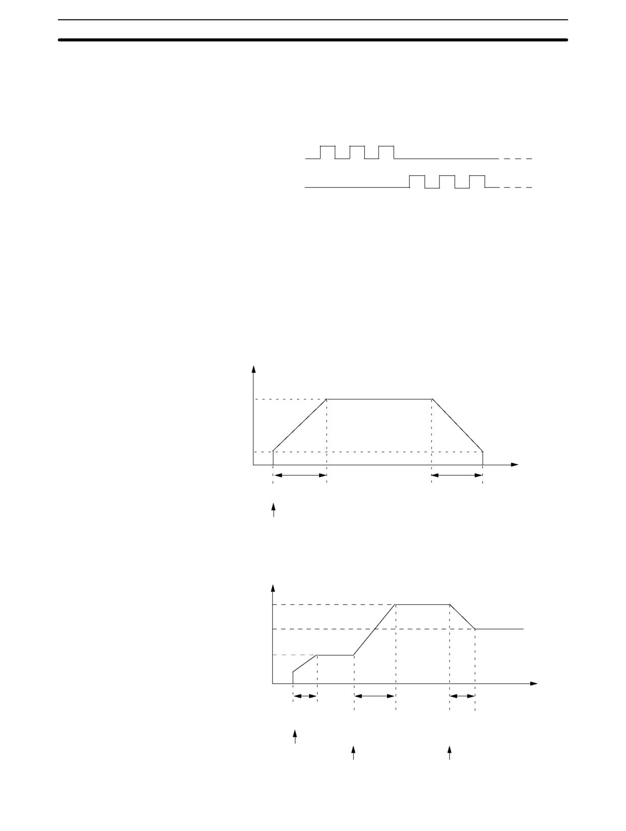
With PWM(--), pulses are output with a variable duty ratio.
ton
Instruction execution: PWM(--)
Pulses are output at the set frequency until stopped.
ton
Duty ratio (D) =
T
Single-phase Pulse Outputs With Trapezoidal Acceleration/Deceleration
• Frequency:
10 Hz to 10 kHz (Set in units of 10 Hz.)
• Acceleration/deceleration rate:
10 Hz/10 ms to 10 kHz/10 ms (Set in units of
10 Hz.)
Pulse + Direction Outputs
• For CW Output:
Output number 01001 (Word 010, bit 01) turned OFF.
Pulses output from output number 01000 (Word 010, bit 00).
• For CCW Output:
Output number 01001 (Word 010, bit 01) turned ON.
Pulses output from output number 01000 (Word 010, bit 00).
01000
Pulse outputs
01001
Direction outputs (OFF: CW operation; ON: CCW operation)
95
CPM2A/CPM2C Pulse Output Functions
Section
2-5
Up/Down Pulse Outputs
• For CW output:
Pulses output from output number 01000 (Word 010, bit 00).
• For CCW output:
Pulses output from output number 01001 (Word 010, bit 01).
01000
CW operation
01001
CCW operation
• Output mode: Continuous and Independent
• Number of pulses: 1 to 16,777,215
• Instructions:
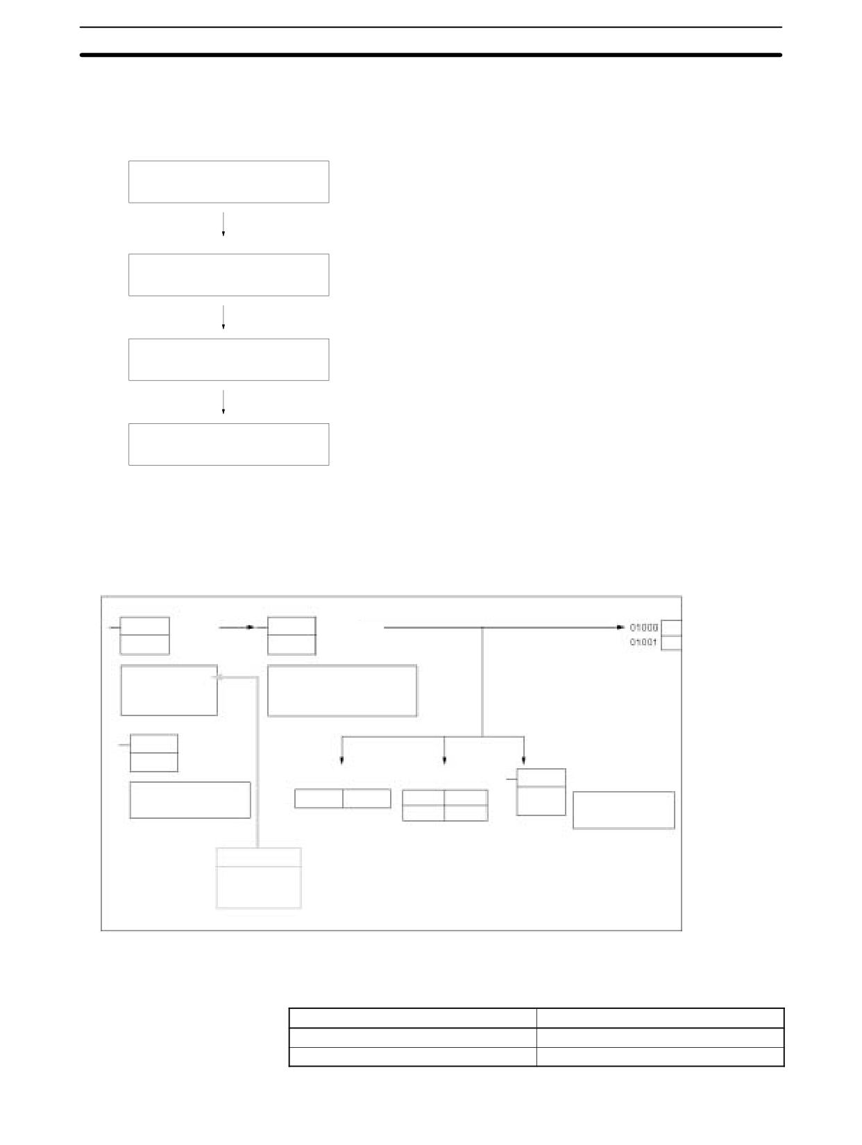
PULS(65) and ACC(--)
• With PULS(65), the number of pulses is set (in independent mode only).
• With ACC(--), the output mode, starting frequency, target frequency, and
acceleration/deceleration rate are set, and the pulse outputs are started.
From when the pulse outputs are started until they are stopped, they are
controlled at a constant-ratio frequency change.
Independent Mode
Pulse output frequency
Instruction execution: PULS(65) + ACC(--) (Independent mode)
In independent mode, deceleration is
carried out at the acceleration/
Target
deceleration rate in effect at the start.
frequency
Starting
frequency
0 Hz
Time
Acceleration
Deceleration
Start
ACC(--)
Continuous Mode
Pulse output frequency
Instruction execution: ACC(--) (Continuous mode)
Target
frequency 2
Target
frequency 3
Target
frequency 1
0 Hz
Time
Acceleration/
deceleration
Acceleration/deceleration Acceleration/deceleration
Start
Acceleration or
Acceleration or
deceleration
deceleration
ACC(--)
ACC(--)
ACC(--)
96
CPM2A/CPM2C Pulse Output Functions
Section
2-5
2-5-1
Using Single-phase Pulse Outputs Without Acceleration and
Deceleration (Fixed Duty Ratio)
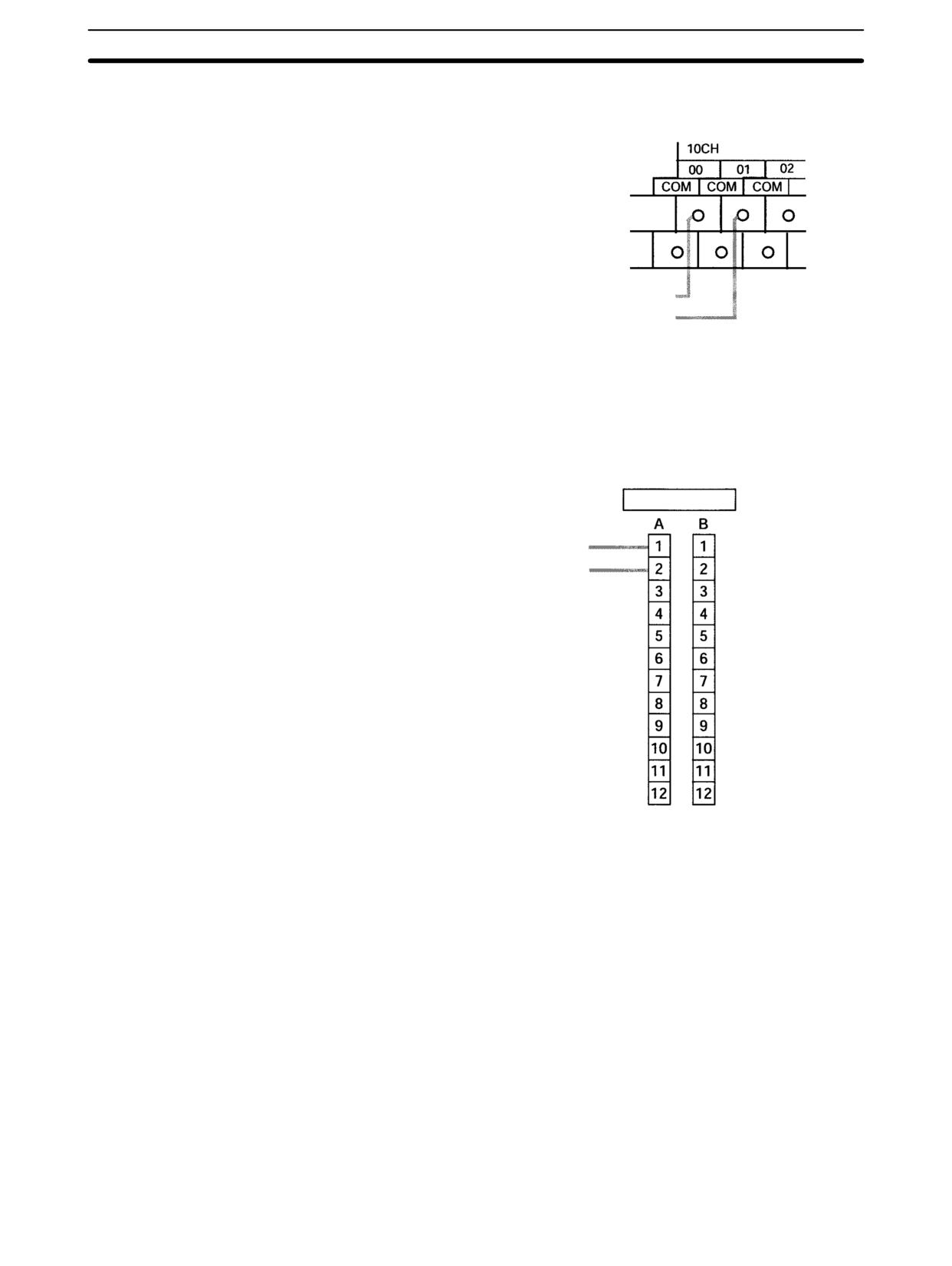
Select the pulse output number.
Pulse output number 0 or 1
Wire the outputs.
Output numbers: 01000 and 01001
PC Setup (DM 6629)
PV coordinate system for pulse output numbers 0 and 1
PULS(65): For setting the number of output pulses.
Create a ladder diagram program.
SPED(64): For pulse output control without acceleration and deceleration.
INI(61): For stopping pulse outputs and changing the pulse output PV.
PRV(62): For reading the pulse output PV and status.
Single-phase Pulse Outputs
PULS(65)
SET
SPED(64)
SPEED
Pulse output 0
PULSES
OUTPUT
Pulse output 1
instruction
instruction
Specify relative or
Output mode: Continuous or
absolute pulses.
Independent
Pulse output SV
Target frequency: 10 Hz to 10 kHz
(8 digits BCD)
Start pulse outputs.
MODE
INI(61)
Every scan
Every scan
Immediately
CONTROL
instruction
Pulse output status
Pulse output PV
PRV(62)
HIGH-SPEED COUNTER
PV READ instruction
Stop pulse outputs.
AR 11
AR 12
SR 228
SR 229
Read pulse output PV.
Change pulse output PV.
SR 230
SR 231
Read pulse output
status.
PC Setup
DM 6629,
bits 04 to 07
Select either pulse number 0 or 1.
Selecting the Pulse
Output Number
Output number
Pulse output number
01000
0
01001
1
97
CPM2A/CPM2C Pulse Output Functions
Section
2-5
Wiring the Outputs
Wire the CPM2A outputs as shown in the following illustration. (Pulses can be
output independently from pulse outputs 0 and 1.)
Output 01000: Pulse output 0 (single-phase output)
Output 01001: Pulse output 1 (single-phase output)
Wire the CPM2C outputs as shown in the following illustration. (Pulses can be
output independently from pulse outputs 0 and 1.)
Note The following examples are for Fujitsu-compatible connectors. Output bit ad-
dresses and connector pin numbers depend on the models. Refer to the CPM2C
Operation Manual (W356) or the CPM2C-S Operation Manual (W377) for de-
tails.
Output connector (See above note.)
01000: Pulse output 0 (single-phase output)
01001: Pulse output 1 (single-phase output)
98
CPM2A/CPM2C Pulse Output Functions
Section
2-5
PC Setup
Make the following settings in the PC Setup.
Word
Bits
Function
Setting
DM 6629
00 to 03
Pulse 0 PV coordinate
0: Relative coordinate
Either 0 or
system
system
1
04 to 07
Pulse 1 PV coordinate
1: Absolute coordinate
system
system
DM 6642
08 to 15
High-speed counter
00: Do not use.
Either 00 or
setting
01
01: Use as high-speed
counter
02: Use as
synchronized pulse
control (10 to 500 Hz).
03: Use as
synchronized pulse
control (20 Hz to 1
kHz).
04: Use as
synchronized pulse
control (300 Hz to 20
kHz).
If absolute pulses are specified with PULS(65), be sure to set the absolute coor-
dinate system (1).
Synchronized pulse control cannot be used simultaneously.
The settings will go into effect when the mode is changed (from PROGRAM to
MONITOR/RUN) or when the power supply is turned ON to the PC.
Ladder Diagram
The following table shows the instruction operations related to pulse outputs
Programming
without acceleration and deceleration (fixed duty ratio).
Instruction
Control
Operation
(@)PULS(65)
Set number of pulses
Sets the number of pulses to be output
in independent mode.
(@)SPED(64)
Set frequency and start
Sets the frequency for outputs in the
pulse outputs
independent mode or continuous mode,
and starts the pulse outputs.
Change frequency
Changes the frequency for outputs in
the independent mode or continuous
mode.
Stop pulse outputs
Stops the pulse outputs (by changing
the speed to a frequency of 0 Hz).
(@)INI(61)
Stop pulse outputs
Stops the pulse outputs.
Change pulse output PV
Changes the pulse output PV.
(@)PRV(62)
Read pulse output PV
Reads the pulse output PV.
Read pulse output status
Reads the pulse output status.
The following table shows which instructions can be executed during pulse out-
puts without acceleration and deceleration.
PULS(65)
SPED(64)
INI(61)
PRV(62)
ACC(--)
PWM(--)
Continuous mode
No
Yes (See note 2.)
Yes (See note 1.)
Yes
No
No
Independent mode
No
Yes (See note 2.)
Yes (See note 1.)
Yes
No
No
Note
1. This instruction can be executed only while pulse outputs are stopped. The
PV cannot be changed while pulses are being output. If the PV needs to be
changed, be sure to stop the pulse output first.
2. This instruction can be used only for changing the frequency and stopping
the pulse output. It cannot be used for switching between independent
mode and continuous mode.
99
CPM2A/CPM2C Pulse Output Functions
Section
2-5
The following table shows the words and bits related to pulse outputs without
acceleration and deceleration (fixed duty ratio).
Word
Bits
Name
Contents
228
00 to 15
Pulse output PV 0, rightmost 4 digits
Cannot be used as
work bits even when
229
00 to 15
Pulse output PV 0, leftmost 4 digits
not used as pu lse
230
00 to 15
Pulse output PV 1, rightmost 4 digits
outputs.
231
00 to 15
Pulse output PV 1, leftmost 4 digits
252
04
Pulse output 0 PV reset
Clears PV 0 when ON.
05
Pulse output 1 PV reset
Clears PV 1 when ON.
AR 11
12
Pulse output 0 PV overflow/underflow
ON: Occurred
OFF: Normal
13
Number of pulses set for pulse output 0
ON: Set (by PULS(65))
OFF: Not set
14
Pulse output completed for pulse
ON: Completed (by
output 0
SPED(64))
OFF: Not completed
15
Pulse output in progress for pulse
ON: In progress (by
output 0
SPED(64))
OFF: Stopped
AR 12
12
Pulse output 1 PV overflow/underflow
ON: Occurred
OFF: Normal
13
Number of pulses set for pulse output 1
ON: Set (by PULS(65))
OFF: Not set
14
Pulse output completed for pulse
ON: Completed (by
output 1
SPED(64))
OFF: Not completed
15
Pulse output in progress for pulse
ON: In progress (by
output 0
SPED(64))
OFF: Stopped
Set Number of Pulses
Specify the number of pulses to be output in independent mode.
(@)PULS(65)
P
Port specifier (000: Pulse output 0; 010: Pulse output 1)
D
Type of Pulse Output (000: Relative pulses; 001: Absolute pulses) (See note.)
N
Beginning word of setting for number of pulses
N
Rightmost 4 digits
Number of pulses (Rightmost, leftmost digits)
Register the number of pulses to be set.
N+1
Leftmost 4 digits
96,777,215 to 16,777,215
Negative numbers are expressed by turning ON
the leftmost bit.
Type of Pulse Output
000:
Relative pulses (SV for number of pulses = Number of pulses moved)
001:
Absolute pulses (SV for number of pulses = The next PV on the absolute coordinate system,
i.e., the pulse output PV + number of pulses moved)*
*Absolute pulses can only be specified by PULS(65) when the PV coordinate system
in the PC Setup is set for an absolute coordinate system.
Set Frequency and Start Pulse Outputs
Change Frequency
These functions set the pulse output number, the output mode, and the frequen-
100
CPM2A/CPM2C Pulse Output Functions
Section
2-5
cy, and begin pulse outputs. They can also be used to change the frequency if
pulse outputs are already in progress.
(@)SPED(64)
P
Port specifier (000: Pulse output 0; 010: Pulse output 1)
M
Mode designation (000: Independent; 001: Continuous)
F
Target frequency data word
F
Target frequency
Register the target frequency data to be set.
#0001 to #1000 (4 digits BCD): 10 Hz to 10 kHz
#0000: Pulse output stopped
Change Pulse Output PV
Resetting Pulse Output PV
This function changes the pulse output present value (PV). The PV can also be
cleared by using SR 25204 and SR 25205.
(@)INI(61)
P
Port specifier (000: Pulse output 0; 010: Pulse output 1)
004
Control designation (004: Change pulse output PV)
C2
Beginning word for PV change data
C2
Rightmost 4 digits
Change PV data (Rightmost, leftmost digits)
C2+1
Leftmost 4 digits
Register the PV data to be changed.
96,777,215 to 16,777,215
Negative numbers are expressed by turning
ON the leftmost bit.
The pulse output PV can only be changed or reset while pulse outputs are
stopped. Check to be sure that the Pulse Output In Progress Flags (AR 1115 and
AR 1215) have been turned OFF.
Stop Pulse Outputs
This function stops the pulse outputs.
Using SPED(64)
(@)SPED(64)
P
Port specifier (000: Pulse output 0; 010: Pulse output 1)
M
Mode designation (000: Independent; 001: Continuous)
F
Target frequency data word
F
#0000
Specifies a frequency of 0 Hz.
Using INI(61)
(@)INI(61)
P
Port specifier (000: Pulse output 0; 010: Pulse output 1)
003
Control designation (003: Stop pulse outputs)
000
Fixed: 000
Besides executing the instructions shown above, it is also possible to stop pulse
outputs by stopping operation (PROGRAM mode).
Read Pulse Output PV
This function reads the pulse output PV.
101
CPM2A/CPM2C Pulse Output Functions
Section
2-5
Using an Instruction
(@)PRV(62)
P
Port specifier (000: Pulse output 0; 010: Pulse output 1)
003
Control designation (003: Read pulse output PV)
D
Beginning word for storing pulse output PV
D
Rightmost 4 digits
Pulse output PV (rightmost, leftmost digits)
The PV data that is read is stored here.
D+1
Leftmost 4 digits
96,777,215 to 16,777,215
Negative numbers are expressed by turning
ON the leftmost bit.
Using Data Areas
As shown in the following illustration, the pulse output PV for pulse output 0 is
stored in words 228 and 229, and the pulse output PV for pulse output 1 is stored
in words 230 and 231.
Pulse Output 0
Pulse Output 1
Word 228
PV (Rightmost)
Word 230
PV (Rightmost)
Word 229
PV (Leftmost)
Word 231
PV (Leftmost)
Words 228 to 231 are refreshed with every scan, so there may be a discrepancy
from the exact PV at any given time.
Words 228 to 231 cannot be used as work words even when pulse outputs are
not being used.
When the PV is read by executing PRV(62), words 228 to 231 are refreshed with
the same timing.
Read Pulse Output Status
This function reads the pulse output status.
Using an Instruction
(@)PRV(62)
P
Port specifier (000: Pulse output 0; 010: Pulse output 1)
001
Control designation (001: Read pulse output status)
D
Word for storing pulse output status
Pulse output status
Number of pulses
0: Constant speed; 1: Accelerating/decelerating
0: Not set
Pulse output PV overflow/underflow
1: Set
0: Normal; 1: Overflow or underflow occurred
Pulse output completion
Pulse output in progress
0: Not completed
0: Stopped
1: Completed
1: Output in progress
Using Data Areas
As shown in the following illustration, the pulse output status for pulse output 0 is
stored in AR 11, and the pulse output status for pulse output 1 is stored in AR 12.
AR 11: Pulse output 0
AR 12: Pulse output 1
Pulse output status:
0: Constant speed;
Pulse output in progress
1: Accelerating/decelerating
0: Stopped
1: Output in progress
Pulse output PV overflow/underflow
0: Normal
Pulse output completion
1: Overflow or underflow occurred
0: Not completed
1: Completed
Number of pulses
0: Not set
1: Set
102
CPM2A/CPM2C Pulse Output Functions
Section
2-5
Note The flags in AR 11 and AR 12 are refreshed once each cycle, so the values in
these words may not reflect the actual status during each cycle, but the flags in
AR 11 and AR 12 are refreshed when the status is read with PRV(62).
Relationship Between Status and Operation
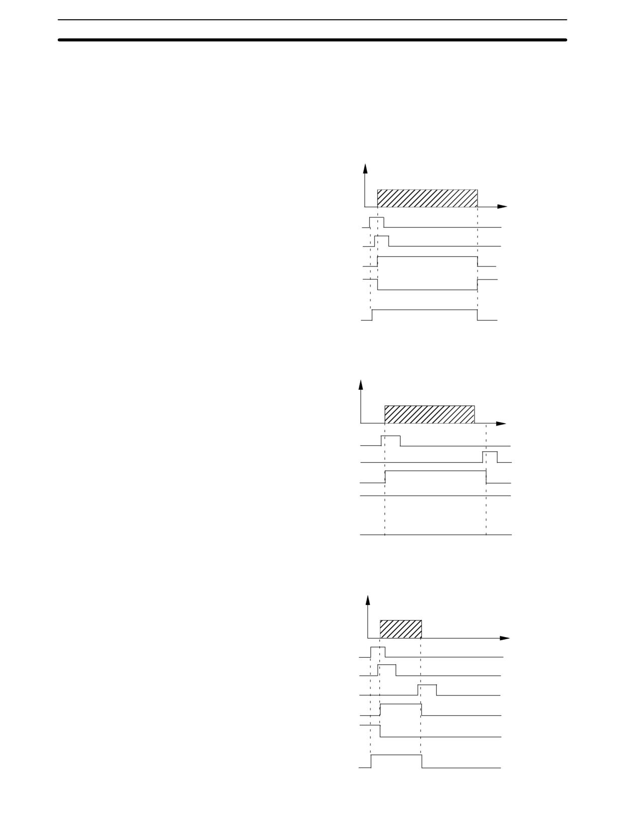
Independent Mode (Without Acceleration and Deceleration)
Frequency
Time
PULS(65) execution
SPED(64) execution
Output in progress
Output completed
Number of pulses set
Continuous Mode
Frequency
Time
SPED(64) execution
INI(61) execution
Output in progress
Output completed
Number of pulses set
Stopping Output in Independent Mode (Without Acceleration and Deceleration)
Frequency
Time
PULS(65) execution
SPED(64) execution
INI(61) execution
Output in progress
Output completed
Number of pulses set
103
CPM2A/CPM2C Pulse Output Functions
Section
2-5
Application Examples
Positioning
Explanation
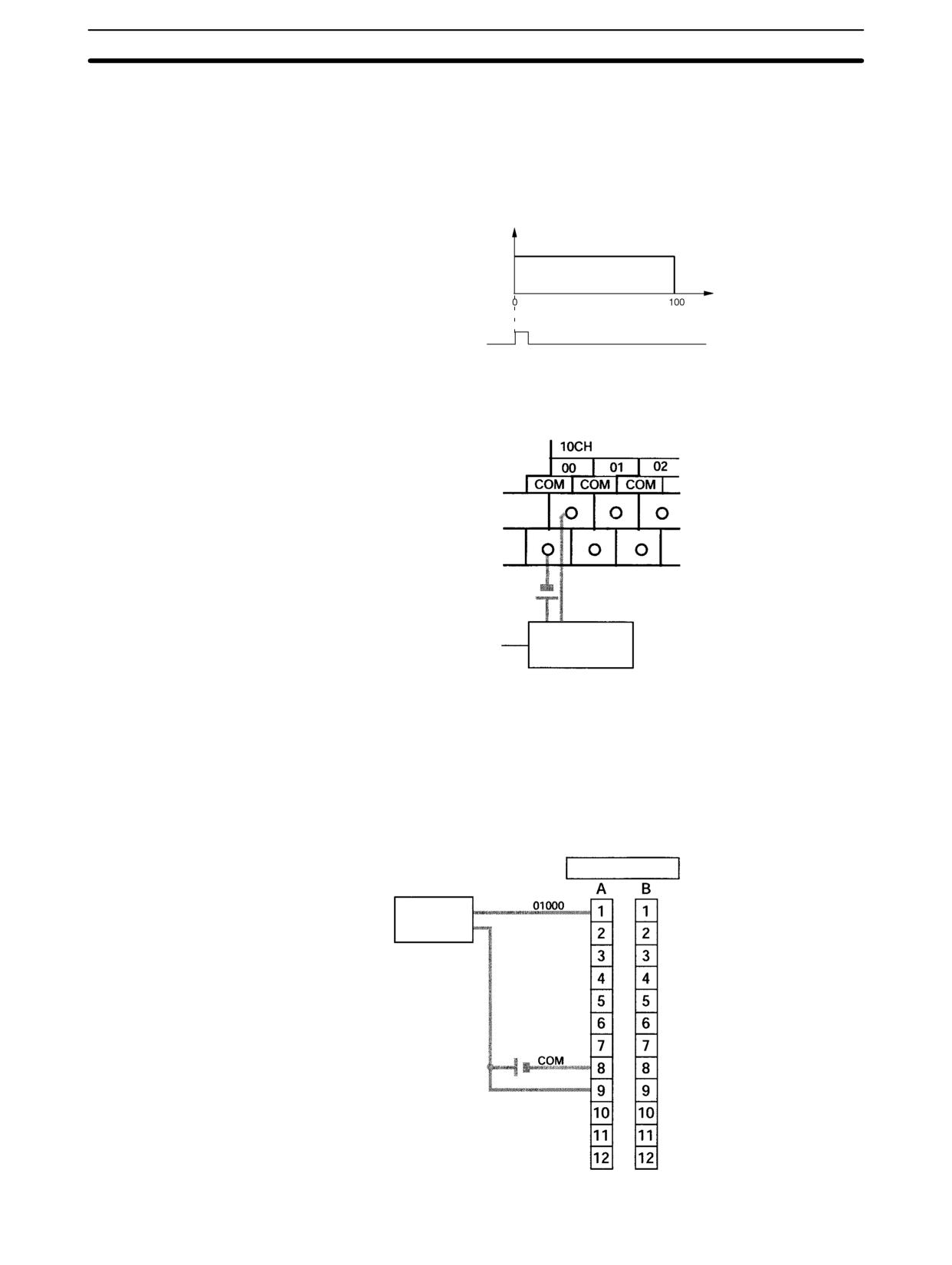
In this example, when the execution condition (00005) turns ON, 100 pulses are
output from output 01000 (pulse output 0) at a frequency of 60 Hz.
Frequency
60 Hz
Number of pulses
Execution condition
(00005)
Wiring
Wire the CPM2A to the motor driver as shown in the following illustration.
Motor Driver
Wire the CPM2C to the motor driver as shown in the following illustration. In this
case, a CPU Unit with sinking transistor outputs is used.
Note The following examples are for Fujitsu-compatible connectors. Output bit ad-
dresses and connector pin numbers depend on the models. Refer to the CPM2C
Operation Manual (W356) or the CPM2C-S Operation Manual (W377) for de-
tails.
Output connector (See above note.)
Motor Driver
24 VDC
104
CPM2A/CPM2C Pulse Output Functions
Section
2-5
PC Setup
15
0
DM 6629
0
Sets the coordinate system for pulse output 0 as relative.
DM 6642
0
0
Set for other than synchronized pulse control.
(Set to 01jj when using the high-speed counter.)
Programming
00005 (Execution condition)
(13)
Detects turning ON of execution condition.
PLUS(65)
Sets number of pulses.
Pulse output 0
Relative pulses
Beginning word for pulse
DM 0000
Number of pulses:
SV data
DM 0001
100
SPED(64) Sets frequency and starts pulse output.
Pulse output 0
Independent mode
Frequency: 60 Hz
JOG Operation
Explanation
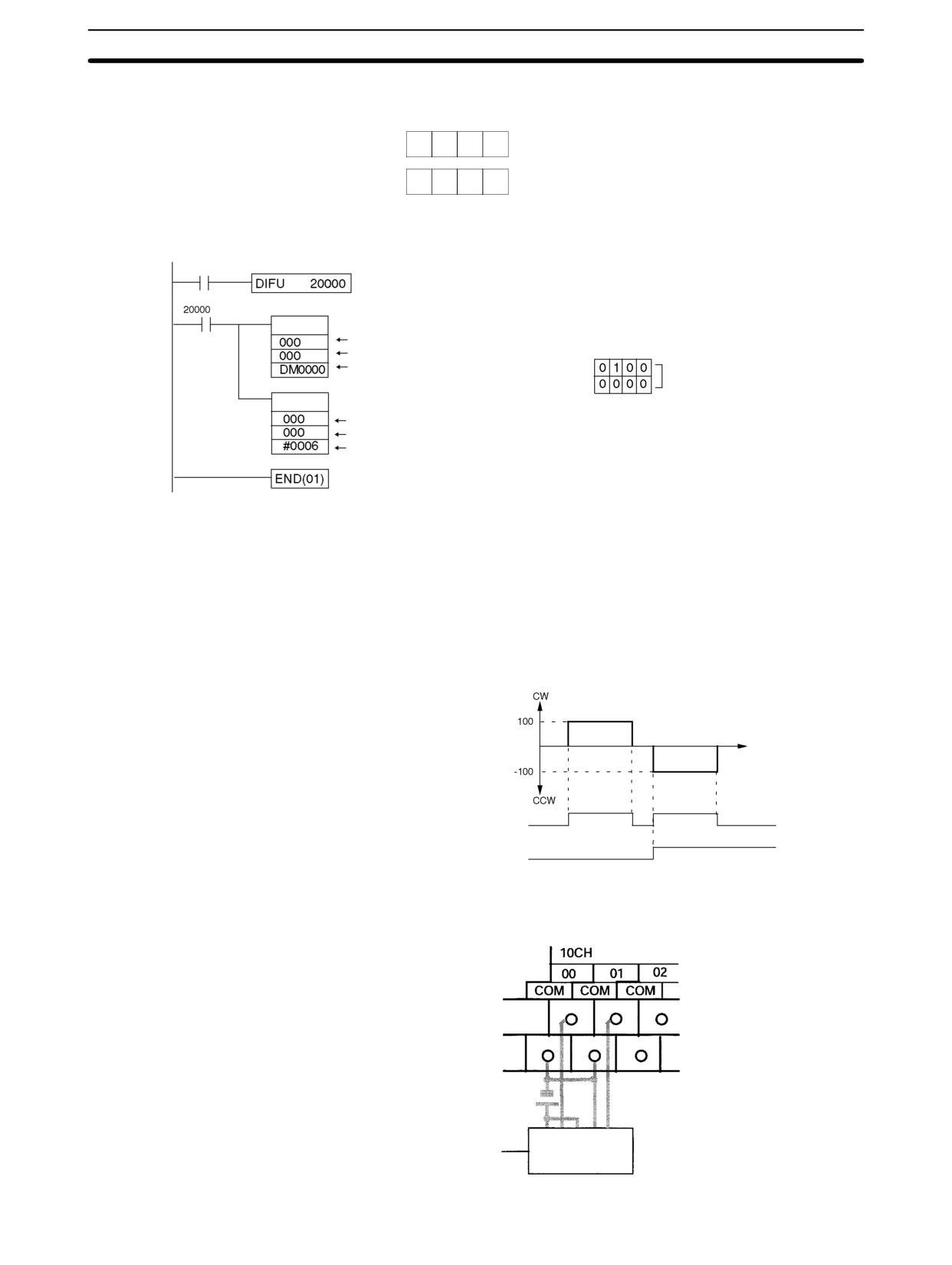
In this example, when the execution condition (00005) turns ON, JOG pulses are
output at a frequency of 100 Hz from either output 01000 (pulse output 0) or out-
put 01001 (pulse output 1). When the execution condition (00005) turns OFF,
the output is stopped. Switching between output 01000 (pulse output 0) and out-
put 01001 (pulse output 1) is performed by means of the direction designator
(00006).
Frequency
(direction)
Time
Execution condition
(00005)
Direction designator
(00006)
Wiring
Wire the CPM2A to the motor driver as shown in the following illustration.
Motor Driver
105
CPM2A/CPM2C Pulse Output Functions
Section
2-5
Wire the CPM2C to the motor driver as shown in the following illustration. In this
case, a CPU Unit with sinking transistor outputs is used.
Note The following examples are for Fujitsu-compatible connectors. Output bit ad-
dresses and connector pin numbers depend on the models. Refer to the CPM2C
Operation Manual (W356) or the CPM2C-S Operation Manual (W377) for de-
tails.
Output connector (See above note.)
Motor
Driver
24 VDC
Note Refer to page operation manual for details on wiring outputs.
PC Setup
15
0
DM 6629
0
0
Sets the coordinate system for pulse outputs 0 and 1 as relative.
DM 6642
0
0
Set for other than synchronized pulse control.
(Set to 01jj when using the high-speed counter.)
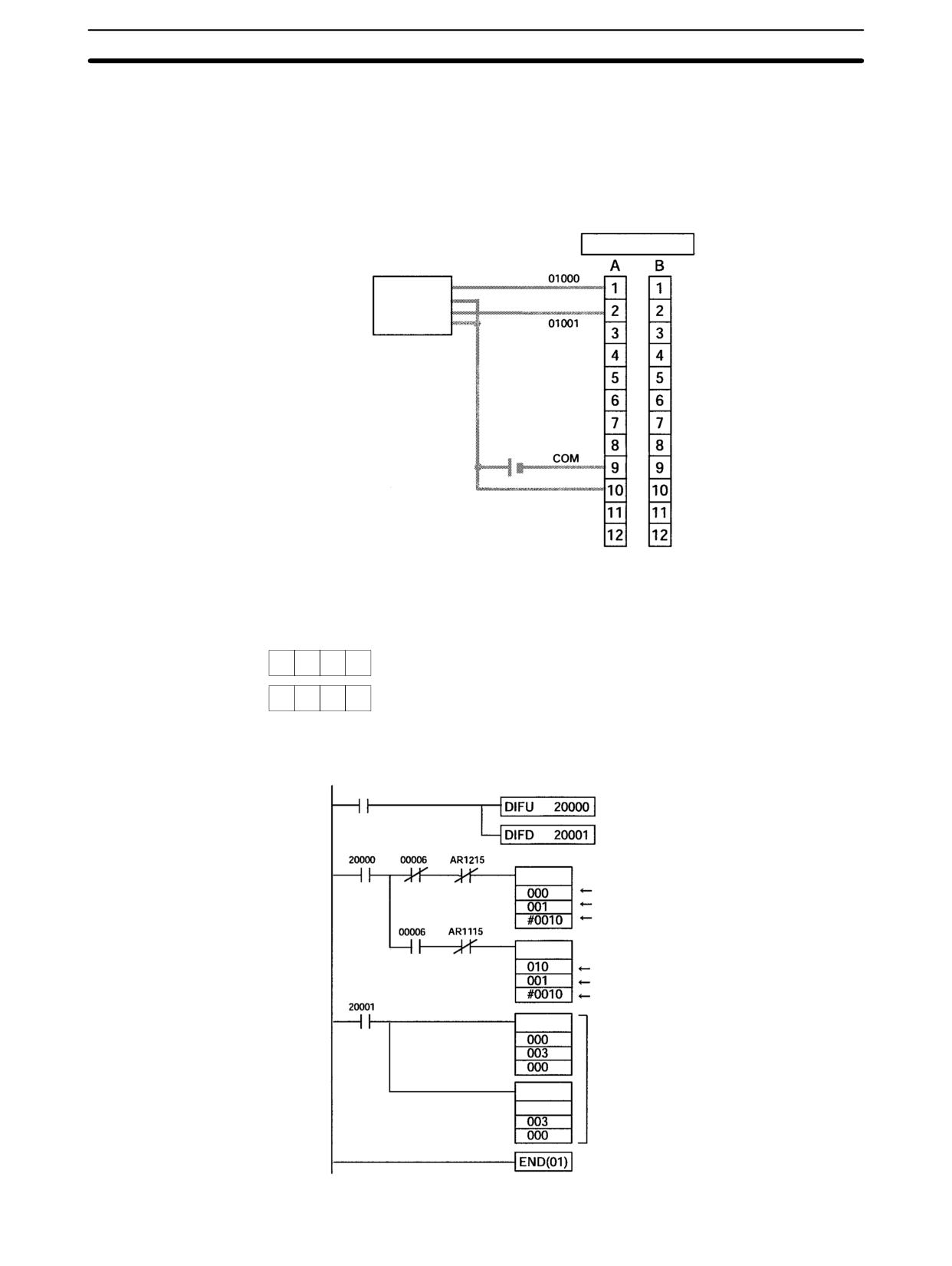
Programming
00005 (Execution condition)
(13)
Detects turning ON of execution condition.
Detects turning OFF of execution condition.
(14)
(Direction designator)
Output in CW direction
SPED(64)
Pulse output 0
Continuous mode
Output frequency: 100 Hz
Output in CCW direction
SPED(64)
Pulse output 1
Continuous mode
Output frequency: 100 Hz
INI(61)
Stops pulse outputs 0 and 1.
INI(61)
010
106
CPM2A/CPM2C Pulse Output Functions
Section
2-5
2-5-2
Using Pulse Outputs With Variable Duty Ratio
Select the pulse output number.
Pulse output number 0 or 1
Wire the outputs.
Output numbers: 01000 and 01001
PWM(--): For setting the frequency and duty ratio.
Create a ladder diagram program.
INI(61): For stopping pulse outputs.
PRV(62): For reading the pulse output status.
Pulse Outputs With Variable Duty Ratio
PWM(--)
PULSE WITH
Pulse output 0
VARIABLE DUTY
Pulse output 1
RATIO instruction
(Either 01000 or 01001
Target frequency: 0.1 to 999.9 Hz
can be used.)
Duty ratio: 0 to 100%
(Note: The duty ratio is the ratio
of ON time to pulse frequency.)
Start pulse outputs
Every scan
Every scan
Immediately
INI(61)
HIGH-SPEED
MODE CONTROL
instruction
COUNTER PV
Pulse output status
PRV(62)
READ instruction
AR 11
AR 12
Stop pulse outputs
Read pulse
output status.
Select either pulse output 0 or 1.
Selecting the Pulse
Output Number
Output number
Pulse output number
01000
0
01001
1
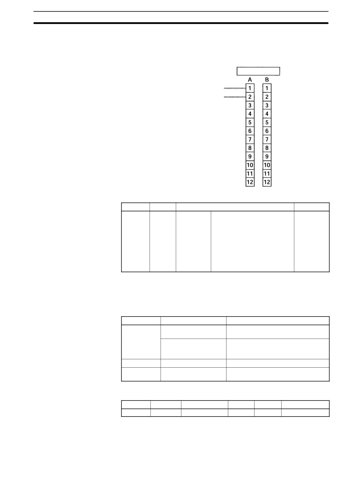
Wiring the Outputs
Wire the CPM2A outputs as shown in the following illustration. (Pulses can be
output independently from pulse outputs 0 and 1.)
Output 01000: Pulse output 0 (single-phase output)
Output 01001: Pulse output 1 (single-phase output)
Wire the CPM2C outputs as shown in the following illustration. (Pulses can be
output independently from pulse outputs 0 and 1.)
107
CPM2A/CPM2C Pulse Output Functions
Section
2-5
Note The following examples are for Fujitsu-compatible connectors. Output bit ad-
dresses and connector pin numbers depend on the models. Refer to the CPM2C
Operation Manual (W356) or the CPM2C-S Operation Manual (W377) for de-
tails.
Output connector (See above note.)
01000: Pulse output 0 (single-phase output)
01001: Pulse output 1 (single-phase output)
PC Setup
Make the following settings in the PC Setup.
Word
Bits
Function
Setting
DM 6642
08 to 15
High-speed
00: Do not use.
Either 00 or
counter
01
01: Use as high-speed counter
setting
02: Use as synchronized pulse
control (10 to 500 Hz).
03: Use as synchronized pulse
control (20 Hz to 1 kHz).
04: Use as synchronized pulse
control (300 Hz to 20 kHz).
Synchronized pulse control cannot be used simultaneously.
The settings will go into effect when the mode is changed (from PROGRAM to
MONITOR/RUN) or when the power supply is turned ON to the PC.
Ladder Diagram
The following table shows the instruction operations related to pulse outputs
Programming
with variable duty ratio.
Instruction
Control
Operation
(@)PWM(--)
Pulse output with
Sets the frequency and duty ratio and
variable duty ratio
starts the pulse outputs.
Change duty ratio
Changes the duty ratio during pulse
while pulse outputs with variable duty
ratio are already in progress.
(@)INI(61)
Stop pulse outputs
Stops the pulse outputs.
(@)PRV(62)
Read pulse output status
Reads the pulse output status (during
pulse outputs).
The following table shows which instructions can be executed during pulse out-
puts without acceleration and deceleration.
PULS(65)
SPED(64)
INI(61)
PRV(62)
ACC(--)
PWM(--)
No
No
Yes (See note 1.)
Yes
No
Yes (See note 2.)
Note
1. This instruction can be used only for stopping pulse outputs.
2. This instruction can be used only for changing the duty ratio. The frequency
cannot be changed while pulses are being output. If the frequency needs to
be changed, be sure to stop the pulse output first.
108
CPM2A/CPM2C Pulse Output Functions
Section
2-5
The following table shows the words and bits related to pulse outputs with vari-
able duty ratio.
Word
Bit
Name
Contents
AR 11
15
Pulse output in progress
ON: In progress (by SPED(64),
for pulse output 0
ACC(--), or PWM(--))
OFF: Stopped
AR 12
15
Pulse output in progress
ON: In progress (by SPED(64),
for pulse output 1
ACC(--), or PWM(--))
OFF: Stopped
Pulse Output With Variable Duty Ratio
Change Duty Ratio
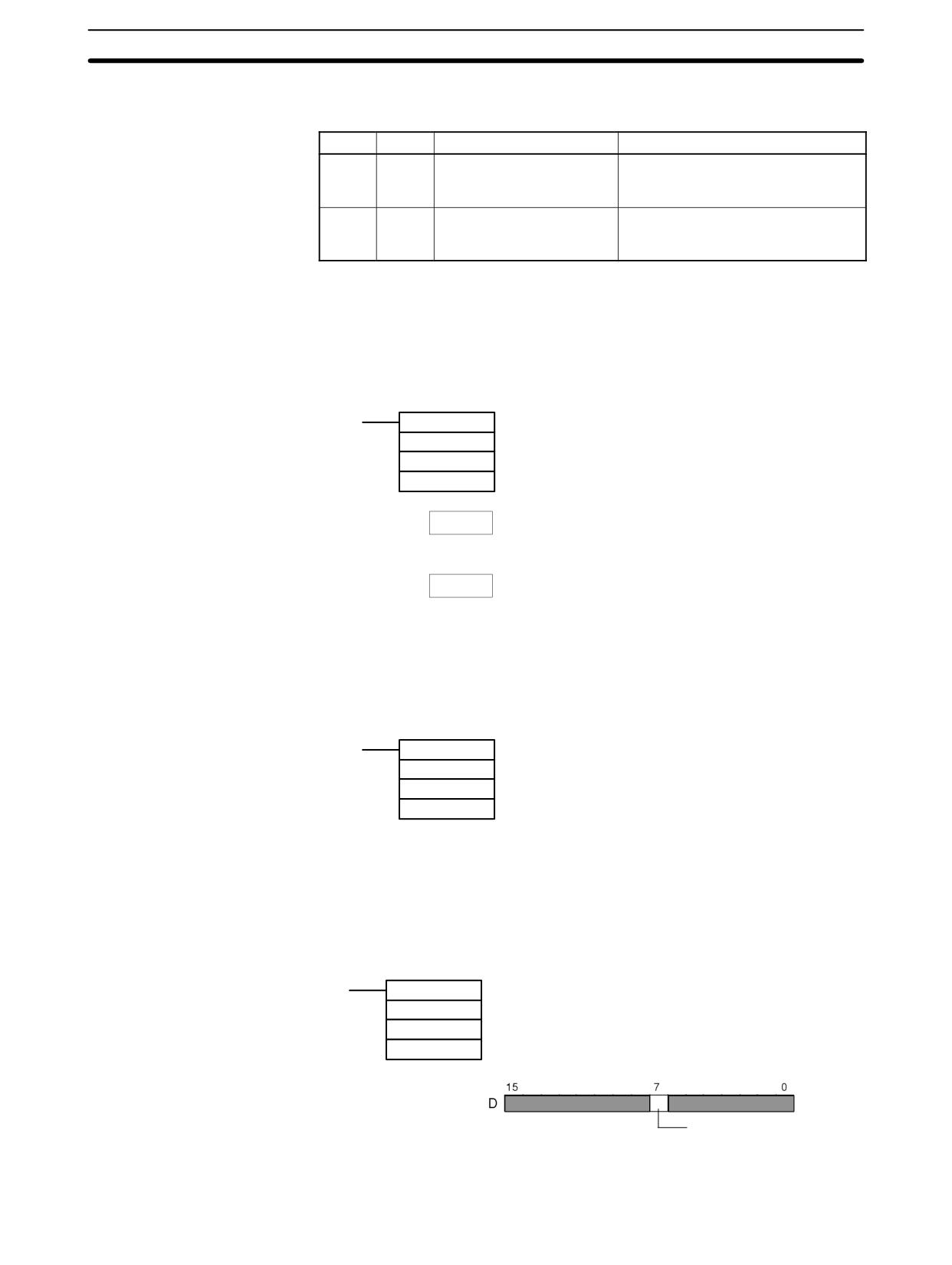
These functions set the position for outputting pulses (01000, 01001), the fre-
quency, and the duty ratio, and start the pulse outputs. By changing the duty ratio
setting and executing PWM(--) again, it is also possible to change the duty ratio
while pulse outputs with variable duty ratio are already in progress.
(@PWM(--)
P Port specifier (000: Pulse output 0; 010: Pulse output 1)
F
Target frequency data word
D
Duty ratio data word
F
Target frequency
Register the target frequency to be set.
#0001 to #9999 (4 digits BCD): 0.1 Hz to 999.9 Hz
D
Duty ratio
Register the duty ratio to be set.
#0000 to #0100 (4 digits BCD): 0% to 100%
The pulse frequency cannot be changed while pulses are being output.
Stop Pulse Outputs
This function stops pulse outputs.
(@)INI(61)
P
Port specifier (000: Pulse output 0; 010: Pulse output 1)
003
Control designation (003: Stop pulse outputs)
000
Fixed: 000
Note The pulse outputs can also be stopped by switching the PC to PROGRAM
mode.
Read Pulse Output Status
This function reads the pulse output status.
Using an Instruction
(@)PRV(62)
P
Port specifier (000: Pulse output 0; 010: Pulse output 1)
001
Control designation (001: Read pulse output status)
D
Beginning word for storing pulse output status
Pulse output in progress
0: Stopped
1: Output in progress
109
CPM2A/CPM2C Pulse Output Functions
Section
2-5
Using Data Areas
As shown in the following illustration, the pulse output status for pulse output 0 is
stored in AR 1115, and the pulse output status for pulse output 1 is stored in AR
1215.
AR 11: Pulse output 0
AR 12: Pulse output 1
Pulse output in progress
0: Stopped
1: Output in progress
Note AR 1115 and AR 1215 are refreshed once each cycle, so the values in these
words may not reflect the actual status during each cycle, but AR 1115 and
AR 1215 are refreshed when the status is read with PRV(62).
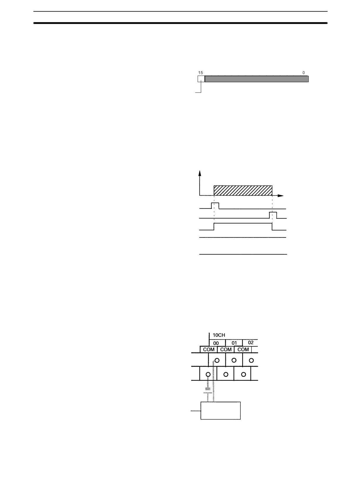
Relationship Between Status and Operation
Continuous Mode (Pulse Output With Variable Duty Ratio)
Frequency
Time
PWM(--) execution
INI(61) execution
Output in progress
Output completion
Set number of pulses
Application Example
Explanation
In this example, when the execution condition (00005) turns ON, variable duty
pulses are output from output 01000 (pulse output 0) at a frequency of 100 Hz.
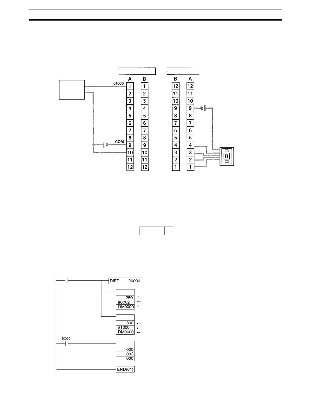
The duty ratio at this time can be changed with the thumbwheel switch 0.
Wiring
Wire the CPM2A to the motor driver and thumbwheel switch as shown in the fol-
lowing illustration.
Motor Driver
Wire the CPM2C to the motor driver and thumbwheel switch as shown in the fol-
lowing illustration. In this case, a CPU Unit with sinking transistor outputs is
used.
110
CPM2A/CPM2C Pulse Output Functions
Section
2-5
Note The following examples are for Fujitsu-compatible connectors. I/O bit addresses
and connector pin numbers depend on the models. Refer to the CPM2C Opera-
tion Manual (W356) or the CPM2C-S Operation Manual (W377) for details.
Output connector
Input connector (See above note.)
Motor Driver
Thumbwheel switch
24 VDC
Note Refer to the operation manual for details on wiring.
PC Setup
15
0
DM 6642
0
0
High-speed counter not used.
(Set for other than synchronized pulse control.)
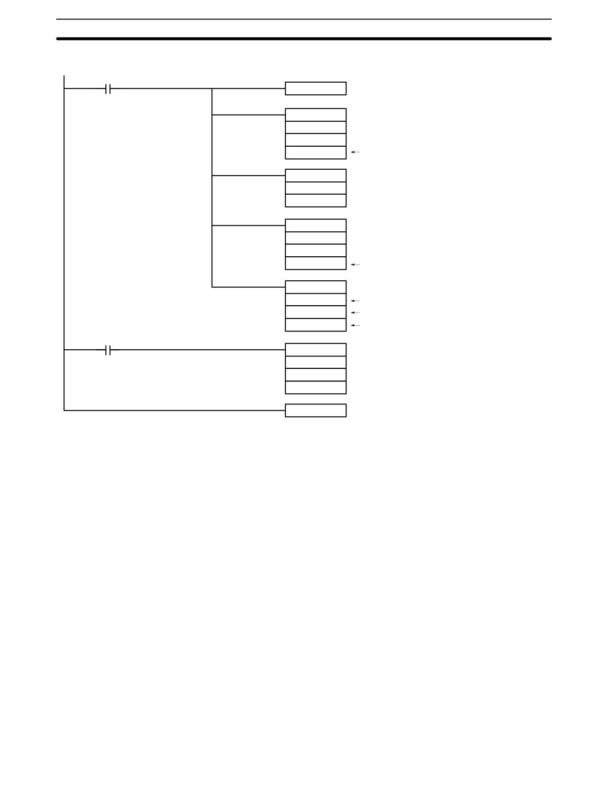
Programming (CPM2A Example)
00005 (Execution condition)
(14)
Detects turning OFF of execution condition.
DIV(33) Changes analog control 0 value to a value from 0 to 100.
Value in SR 250 (Analog control 0 in CPM2A PCs) (see note)
Divide value by 2.
Duty ratio setting
Pulse outputs with variable duty
PWM(--)
Pulse output 0
Output frequency: 100 Hz
Duty ratio setting
INI(61) Stops pulse output 0.
Note The CPM2C is not provided with
an analog control. For external
settings, specify the input word
connected to the thumbwheel
switch.
111
CPM2A/CPM2C Pulse Output Functions
Section
2-5
Programming (CPM2C Example)
Execution condition
DIFD (14)
20000
Detects OFF to ON transition in execution condition.
ANDW (34)
Reads the value from the thumb rotary switch.
000
#000F
DM0100
Value from the thumb rotary switch
BCD (24)
DM0100
DM0101
MUL (32)
DM0101
#0010
DM0102
Duty ratio setting
PWM (--)
Variable duty pulse output
000
Pulse output 0
#1000
Output frequency: 100 Hz
DM0102
Duty ratio setting
20000
INI(61)
Stops pulse output 0
000
003
000
END (01)
112
CPM2A/CPM2C Pulse Output Functions
Section
2-5
2-5-3
Using Pulse Outputs With Trapezoidal Acceleration and
Deceleration
Select the direction control method.
Pulse + direction output or up/down pulse output
Select the pulse output number.
Pulse output number 0
Wire the outputs.
Output numbers: 01000 and 01001
PC Setup (DM 6629)
PV coordinate system for pulse output number 0
PULS(65): For setting the number of output pulses.
Create a ladder diagram program.
ACC(--): For controlling pulse outputs with trapezoidal acceleration and
deceleration
INI(61): For stopping pulse outputs and changing the pulse output PV.
PRV(62): For reading the pulse output PV and status.
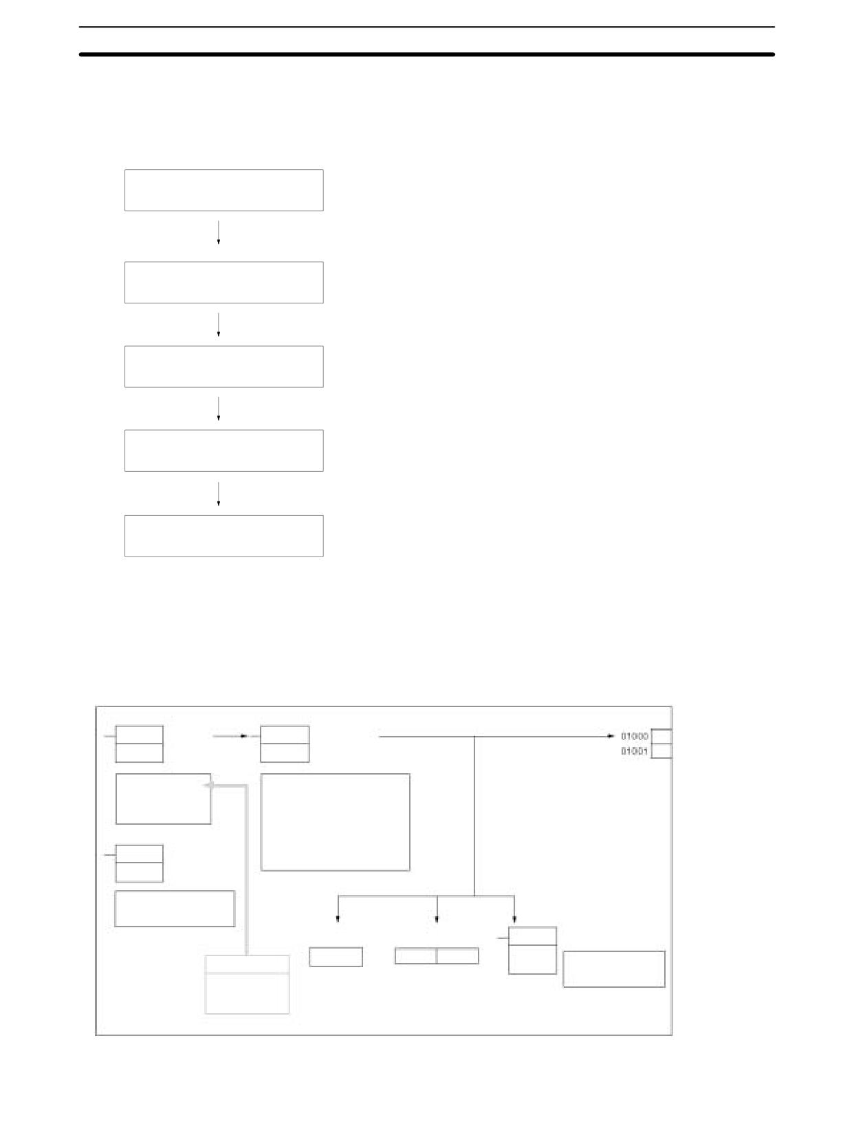
Pulse Outputs With Trapezoidal Acceleration and Deceleration
ACCELERATION
PULS(65) SET
ACC(--)
CONTROL
Pulse, CW
PULSES
instruction
Direction, CCW
instruction
Specify relative or ab-
Mode designation
solute pulses.
Number of output pulses
Starting frequency: 0 Hz to 10 kHz
set value (8 digits BCD)
Target frequency: 10 Hz to 10 kHz
Acceleration/deceleration rate:
10 ms increase/decrease
MODE
10 Hz to 10 kHz
INI(61)
CONTROL
Start pulse outputs.
instruction
Stop pulse outputs.
Every scan
Every scan
Immediately
Change pulse output PV.
HIGH-SPEED
Pulse output status
Pulse output PV PRV(62)
COUNTER PV
READ instruction
AR 11
SR 228
SR 229
Read pulse output PV.
PC Setup
Read pulse output
status.
DM 6629, bits
00 to 03
113
CPM2A/CPM2C Pulse Output Functions
Section
2-5
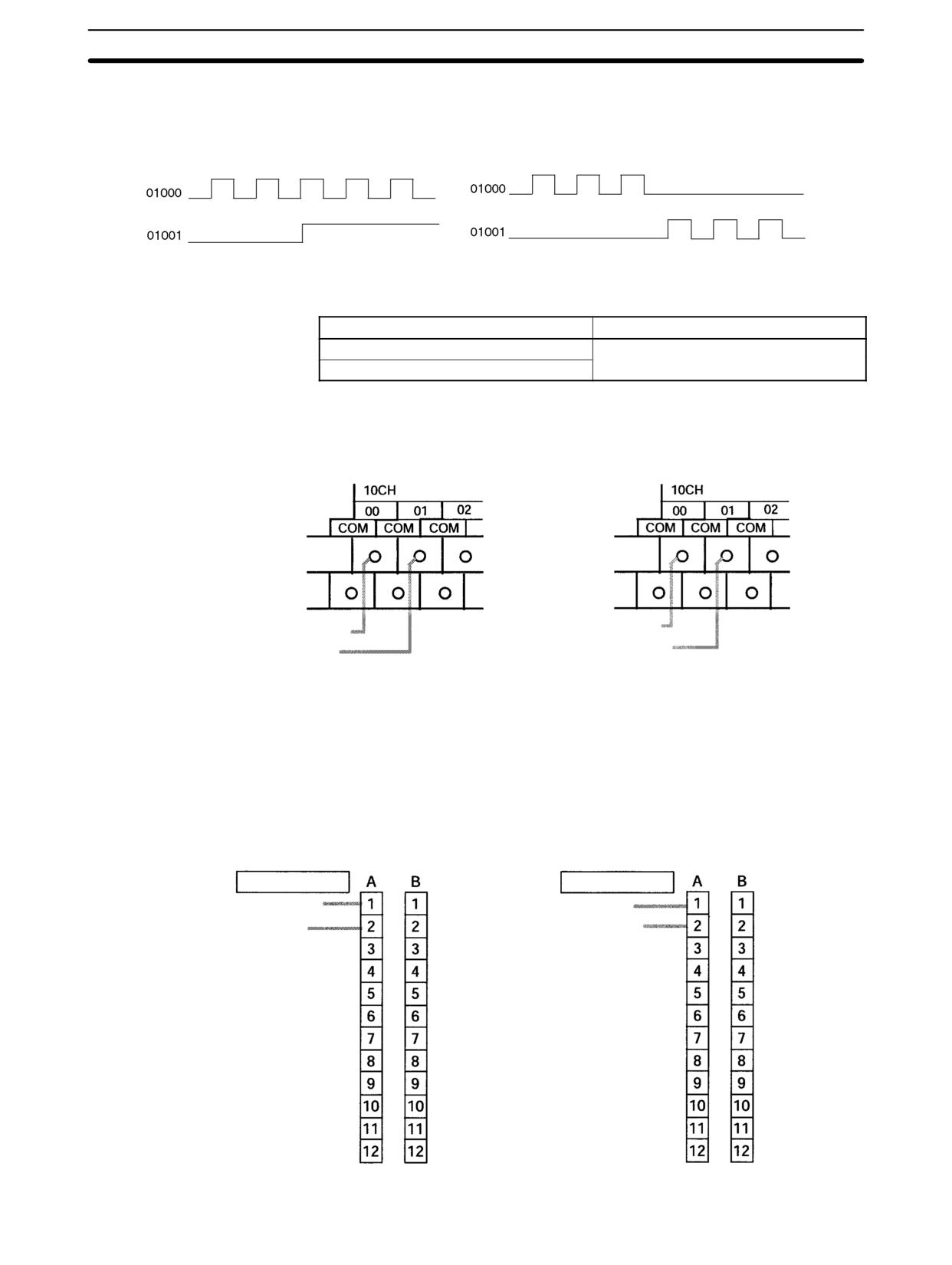
Selecting the Direction
Select the pulse output direction control method according to the type of signal
Control Method
used.
Pulse + Direction Outputs
Up/down Pulse Outputs
Select pulse output 0.
Selecting the Pulse
Output Number
Output number
Pulse output number
01000
0
01001
Wiring the Outputs
Wire the CPM2A outputs as shown in the following illustration.
Pulse + Direction Outputs
Up/down Pulse Outputs
Output 01000: CW output
Output 01000: Pulse output
Output 01001: CCW output
Output 01001: Direction output
Wire the CPM2C outputs as shown in the following illustration.
Note The following examples are for Fujitsu-compatible connectors. Output bit ad-
dresses and connector pin numbers depend on the models. Refer to the CPM2C
Operation Manual (W356) or the CPM2C-S Operation Manual (W377) for de-
tails.
Pulse + Direction Outputs
Up/down Pulse Outputs
(See above note.)
(See above note.)
Output connector
Output connector
01000: Pulse output
01000: CW output
01001: Direction output
01001: CCW output
114
CPM2A/CPM2C Pulse Output Functions
Section
2-5
PC Setup
Make the following settings in the PC Setup.
Word
Bits
Function
Setting
DM 6629
00 to 03
Pulse 0 PV
0: Relative coordinate system
Either 0 or 1
coordinate
1: Absolute coordinate system
system
DM 6642
08 to 15
High-speed
00: Do not use.
Either 00 or
counter
01
01: Use as high-speed counter
setting
02: Use as synchronized pulse
control (10 to 500 Hz).
03: Use as synchronized pulse
control (20 Hz to 1 kHz).
04: Use as synchronized pulse
control (300 Hz to 20 kHz).
If absolute pulses are specified with PULS(65), be sure to set the absolute coor-
dinate system (1).
Synchronized pulse control cannot be used simultaneously.
The settings will go into effect when the mode is changed (from PROGRAM to
MONITOR/RUN) or when the power supply is turned ON to the PC.
Ladder Diagram
The following table shows the instruction operations related to pulse outputs
Programming
with trapezoidal acceleration and deceleration (fixed duty ratio).
Instruction
Control
Operation
(@)PULS(65)
Set number of pulses
Sets the number of pulses to be output
in independent mode.
(@)ACC(--)
Set frequency and start
Sets the target frequency, starting
pulse outputs
frequency, and acceleration/deceleration
rate for outputs in independent mode or
continuous mode, and starts the pulse
outputs.
Change frequency
Changes the frequency during pulse
output in continuous mode by
accelerating or decelerating according
to the specified
acceleration/deceleration rate.
Stop pulse outputs
Decelerates pulse outputs to a stop
according to the specified
acceleration/deceleration rate.
(@)INI(61)
Stop (decelerate stop)
Stops the pulse outputs.
pulse outputs
Change pulse output PV
Changes the pulse output PV.
(@)PRV(62)
Read pulse output PV
Reads the pulse output PV.
Read pulse output status
Reads the pulse output status.
The following table shows which instructions can be executed during pulse out-
puts with trapezoidal acceleration and deceleration.
PULS(65)
SPED(64)
INI(61)
PRV(62)
ACC(--)
PWM(--)
Continuous mode
No
No
Yes (See note 1.)
Yes
No
No
Independent mode
No
No
Yes (See note 1.)
Yes
Yes (See note 2.)
No
Note
1. This instruction can be executed only while pulse outputs are stopped. The
PV cannot be changed while pulses are being output. If the PV needs to be
changed, be sure to stop the pulse output first.
2. This instruction can be used only for changing the frequency and stopping
the pulse output. It cannot be used for switching between independent
mode and continuous mode. Moreover, ACC(--) cannot be received during
acceleration or deceleration.
115
CPM2A/CPM2C Pulse Output Functions
Section
2-5
The following table shows the words and bits related to pulse outputs with trape-
zoidal acceleration and deceleration (fixed duty ratio).
Word
Bits
Name
Contents
228
00 to 15
Pulse output PV 0, rightmost 4 digits
Cannot be used as
work bits even when
229
00 to 15
Pulse output PV 0, leftmost 4 digits
not used as pulse
outputs.
252
04
Pulse output 0 PV reset
Clears PV 0 when ON.
AR 11
11
Pulse output status for pulse output 0
ON: Accelerating or
decelerating
OFF: Constant speed
12
Pulse output 0 PV overflow/underflow
ON: Occurred
OFF: Normal
13
Number of pulses set for pulse output 0
ON: Set
OFF: Not set
14
Pulse output completed for pulse
ON: Completed
output 0
OFF: Not completed
15
Pulse output in progress for pulse
ON: In progress (by
output 0
SPED(64), ACC(--),
or PWM(--))
OFF: Stopped
Set Number of Pulses
Specify the number of pulses to be output in independent mode.
(@)PULS(65)
000
Fixed at 000: Pulse output 0
D
Type of Pulse Output (000: Relative pulses; 001: Absolute pulses) (See note.)
N
Beginning word of setting for number of pulses
N
Rightmost 4 digits
Number of pulses (Rightmost, leftmost digits)
Register the number of pulses to be set.
N+1
Leftmost 4 digits
96,777,215 to 16,777,215
Negative numbers are expressed by turning
ON the leftmost bit.
Type of Pulse Output
000:
Relative pulses (SV for number of pulses = Number of pulses moved)
001:
Absolute pulses (SV for number of pulses = The next PV on the absolute coordinate system,
i.e., the pulse output PV + number of pulses moved)*
*Absolute pulses can only be specified by PULS(65) when the PV coordinate system
in the PC Setup is set for an absolute coordinate system.
116
CPM2A/CPM2C Pulse Output Functions
Section
2-5
Set Frequency and Start Pulse Outputs
Change Frequency
These functions set the output mode, the target frequency, the starting frequen-
cy, and the acceleration/deceleration rate, and they begin pulse outputs. They
can also be used to change the frequency, by accelerating or decelerating at the
specified acceleration/deceleration rate, if pulse outputs are already in progress
in continuous mode.
Setting the Frequencies, Acceleration/Deceleration, and Starting Pulse
Outputs in Independent Mode
(@)ACC(--)
000
Fixed at 000: Pulse output 0
M
Output mode designation
T
Beginning word of settings table
M
Output mode
Specify the output mode.
000: Up/down pulse outputs, independent mode
002: Pulse + direction outputs, independent mode
T
Acceleration/deceleration rate (#0001 to #1000 BCD: 10 Hz to 10 kHz)
T+1
Target frequency (#0001 to #1000 BCD: 10 Hz to 10 kHz)
T+2
Starting frequency (#0000 to #1000 BCD: 0 to 10 kHz)
Register the data for each frequency.
The acceleration/deceleration rate is the increase or decrease in the fre-
quency every 10 ms.
Pulse output frequency
Target
frequency
Starting
Number of
frequency
pulses
0 Hz
Time
In independent mode, the acceleration and deceleration
points are determined from the number of pulses, the
acceleration/deceleration rate, the target frequency, and
the the starting frequency.
117
CPM2A/CPM2C Pulse Output Functions
Section
2-5
Setting the Frequency and Acceleration/Deceleration, Starting Pulse Out-
puts, and Changing the Frequency in Continuous Mode
(@)ACC(--)
000
Fixed at 000: Pulse output 0
M
Output mode designation
T
Beginning word of settings table
M
Output mode
Specify the output mode.
010: Up/down pulse output, CW, continuous mode
011: Up/down pulse output, CCW, continuous mode
012: Pulse + direction output, CW, continuous mode
013: Pulse + direction output, CCW, continuous mode
T
Acceleration/deceleration rate (#0001 to #1000 BCD: 10 Hz to 10 kHz)
T+1
Target frequency (#0001 to #1000 BCD: 10 Hz to 10 kHz)
T+2
Starting frequency (#0000 to #1000 BCD: 0 to 10 kHz)
Register the data for each frequency.
The acceleration/deceleration rate is the increase or decrease in the fre-
quency every 10 ms.
Pulse output frequency
Target
frequency
Starting
frequency
0 Hz
Time
In continuous mode, pulses are output at the target frequency until
stopped. The next ACC(--) instruction cannot be received except during
acceleration or deceleration.
Change Pulse Output PV
This function changes the pulse output PV.
(@)INI(61)
000
Fixed at 000: Pulse output 0
004
Control designation (004: Change pulse output PV)
C2
Beginning word for PV change data
C2
Rightmost 4 digits
Change PV data (Rightmost, leftmost digits)
Register the PV data to be changed.
C2+1
Leftmost 4 digits
96,777,215 to 16,777,215
Negative numbers are expressed by turning
ON the leftmost bit.
Note The pulse output PV can be changed only while the pulse output is stopped.
118
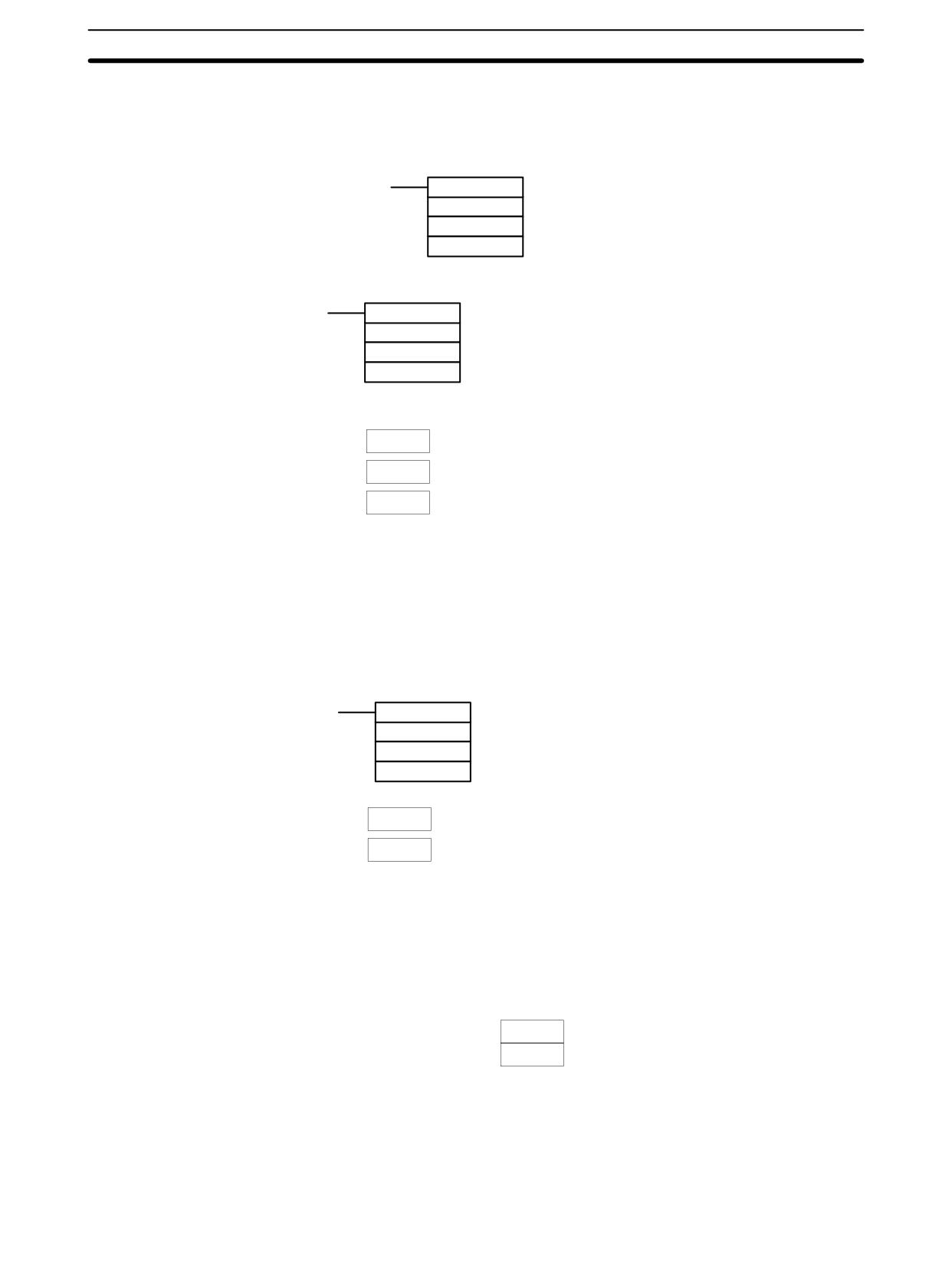
CPM2A/CPM2C Pulse Output Functions
Section
2-5
Stop Pulse Outputs,
Decelerate and Stop Pulse Outputs
These functions stop the pulse outputs.
Stop Pulse Outputs
(@)INI(61)
000
Fixed at 000: Pulse output 0
003
Control designation (003: Stop pulse outputs)
000
Fixed at 000
Decelerate Stop Pulse Outputs
(@)ACC(--)
000
Fixed at 000: Port specifier
000
Mode designation
T
Beginning word of settings table
T
Acceleration/deceleration rate (#0001 to #1000 BCD: 10 Hz to 10 kHz)
T+1
Target frequency (#0000 to #1000 BCD: 0 Hz to 10 kHz)
T+2
Starting frequency (#0000 to #1000 BCD: 0 to 10 kHz)
Register the data for each frequency.
The acceleration/deceleration rate is the increase or decrease in the fre-
quency every 10 ms.
Note The pulse outputs can also be stopped by switching the PC to PROGRAM
mode.
Read Pulse Output PV
This function reads the pulse output PV.
Using an Instruction
(@)PRV(62)
000
Fixed at 000: Pulse output 0
003
Control designation (003: Read pulse output PV)
D
Beginning word for storing pulse output PV
D
Rightmost 4 digits
Pulse output PV (rightmost, leftmost digits)
The PV data that is read is stored here.
D+1
Leftmost 4 digits
96,777,215 to 16,777,215
Negative numbers are expressed by turning
ON the leftmost bit.
Using Data Areas
As shown in the following illustration, the pulse output PV for pulse output 0 is
stored in words 228 and 229.
Pulse Output 0
Word 228
PV (Rightmost)
Word 229
PV (Leftmost)
SR 228 and SR 229 are refreshed once each cycle, so the values in these words
may not reflect the actual status during each cycle. SR 228 and SR 229 are re-
freshed immediately when their status is read with PRV(62).
SR 228 to SR 231 are refreshed with every scan, so there may be a discrepancy
from the exact PV at any given time.
119
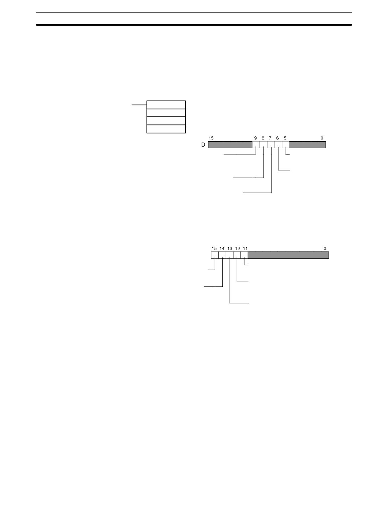
CPM2A/CPM2C Pulse Output Functions
Section
2-5
SR 228 to SR 231 cannot be used as work words even when pulse outputs are
not being used.
When the PV is read by executing PRV(62), SR 228 to SR 231 are refreshed with
the same timing.
Read Pulse Output Status
This function reads the pulse output status.
Using an Instruction
(@)PRV(62)
000
Fixed at 000: Pulse output 0
001
Control designation (001: Read pulse output status)
D
Word for storing pulse output status
Pulse output status
Number of pulses
0: Constant rate
0: Not set
1: Set
1: Accelerating or decelerating
Pulse output completion
Pulse output PV overflow/underflow
0: Not completed
0: Normal; 1: Overflow or underflow occurred
1: Completed
Pulse output in progress
0: Stopped
1: Output in progress
Using Data Areas
As shown in the following illustration, the pulse output status for pulse output 0 is
stored in AR 1111 to AR 1115.
AR 11: Pulse output 0
Pulse output status
Pulse output in progress
0: Constant rate
1: Accelerating or decelerating
0: Stopped
1: Output in progress
Pulse output PV overflow/underflow
Pulse output completion
0: Normal
1: Overflow or underflow occurred
0: Not completed
1: Completed
Number of pulses
0: Not set
1: Set
Note AR 1111 through AR 1115 are refreshed once each cycle, so the values of these
flags may not reflect the actual status, but these flags are refreshed immediately
when their status is read with PRV(62).
120
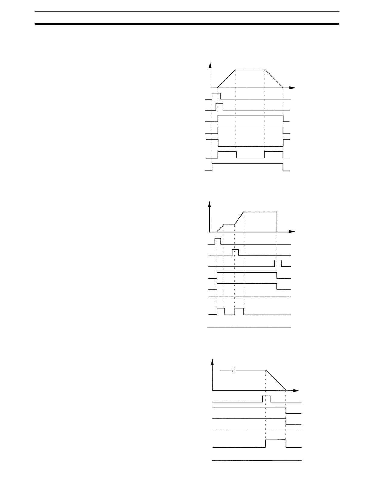
CPM2A/CPM2C Pulse Output Functions
Section
2-5
Relationship Between Status and Operation
Independent Mode with Acceleration and Deceleration
Frequency
Time
PULS(65) execution
ACC(--) execution
Output 0 in progress
Output 1 in progress
Output completion
Output status
Set number of pulses
Continuous Mode with Acceleration and Deceleration 1
Frequency
Time
ACC(--) execution (1)
ACC(--) execution (2)
INI(61) execution
Output 0 in progress
Output 1 in progress
Output completion
Output status
Set number of pulses
Continuous Mode with Acceleration and Deceleration 2
Frequency
Time
ACC(--) execution (Stop)
Output 0 in progress
Output 1 in progress
Output completion
Output status
Set number of pulses
121
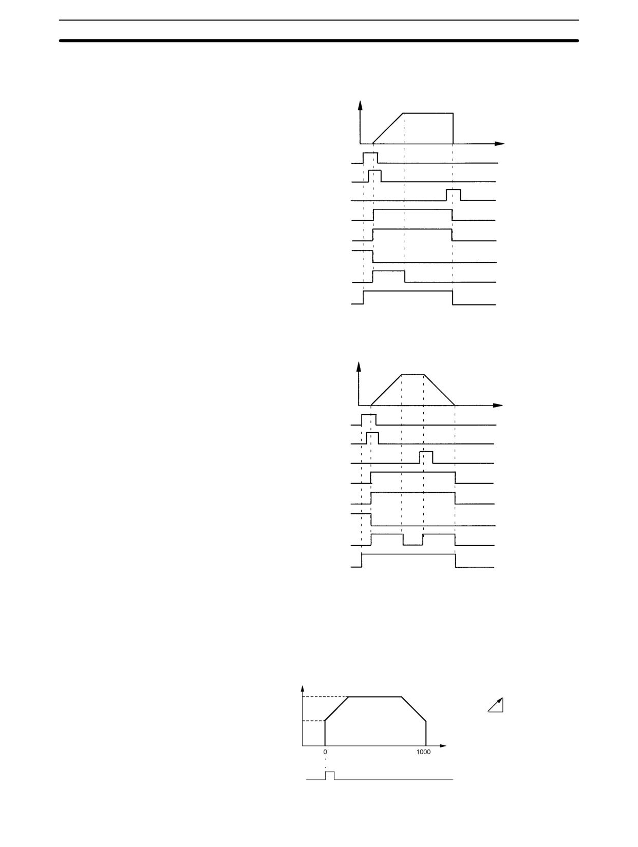
CPM2A/CPM2C Pulse Output Functions
Section
2-5
Stopping Outputs in Continuous Mode
with Acceleration and Deceleration 1
Frequency
Time
PULS(65) execution
ACC(--) execution
INI(61) execution
Output 0 in progress
Output 1 in progress
Output completion
Output status
Set number of pulses
Stopping Outputs in Continuous Mode
with Acceleration and Deceleration 2
Frequency
Time
PULS(65) execution
ACC(--) execution
ACC(--) execution
Output 0 in progress
Output 1 in progress
Output completion
Output status
Set number of pulses
Application Example
Positioning
Explanation
In this example, when the execution condition (00005) turns ON, 1000 pulses
are output from output 01000 (pulse output 0) in a trapezoidal acceleration/de-
celeration pattern as shown in the following diagram.
Frequency (Hz)
Acceleration/deceleration rate
500
10 Hz
10 ms
200
Number of pulses
Execution condition
(00005)
122
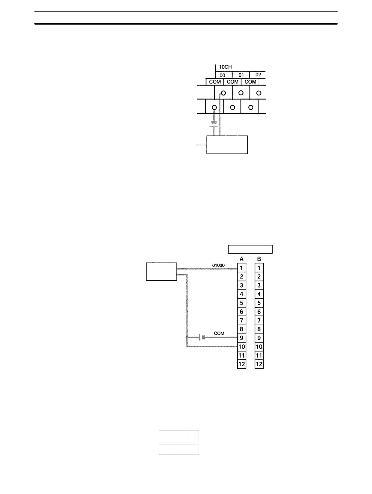
CPM2A/CPM2C Pulse Output Functions
Section
2-5
Wiring
Wire the CPM2A to the motor driver as shown in the following illustration.
Motor Driver
Wire the CPM2C to the motor driver as shown in the following illustration. In this
case, a CPU Unit with sinking transistor outputs is used.
Note The following examples are for Fujitsu-compatible connectors. Output bit ad-
dresses and connector pin numbers depend on the models. Refer to the CPM2C
Operation Manual (W356) or the CPM2C-S Operation Manual (W377) for de-
tails.
Output connector (See above note.)
Motor Driver
24 VDC
Note Refer to the operation manual for details on wiring.
PC Setup
15
0
DM 6629
0
Sets the coordinate system for pulse output 0 as relative.
DM 6642
0
0
High-speed counter not used.
(Set for other than synchronized pulse control.)
123
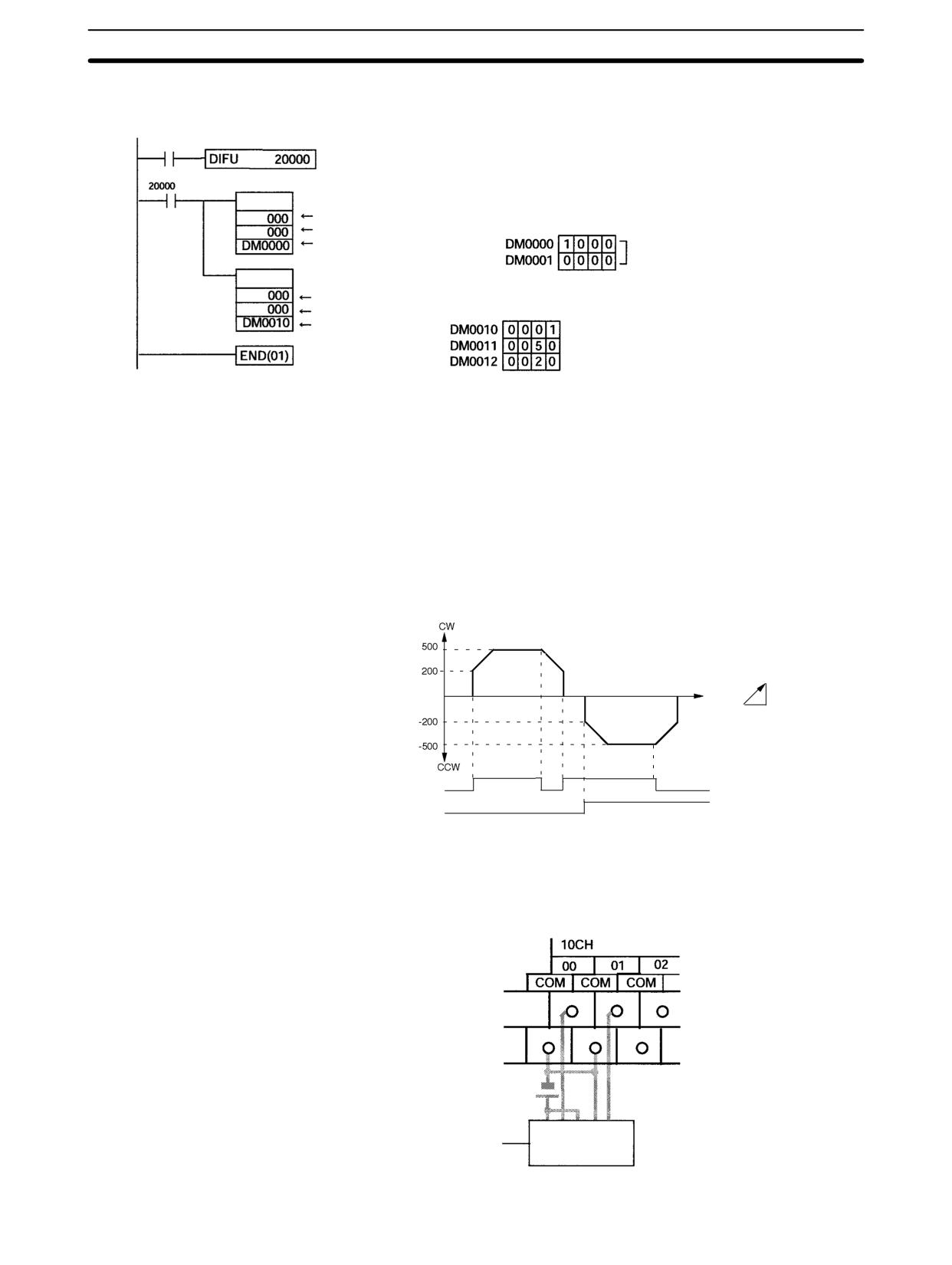
CPM2A/CPM2C Pulse Output Functions
Section
2-5
Programming
00005 (Execution condition)
(13)
Detects turning ON of execution condition.
Sets number of pulses.
PULS(65)
Pulse output 0
Relative pulses
Beginning word for pulse SV
Number of pulses: 1,000
data
Sets frequency and starts pulse output.
ACC(--)
Pulse output 0
Independent mode, up/down pulse output
Beginning word of
Acceleration/deceleration rate: 10 Hz/10 ms
settings table
Target frequency: 500 Hz
Starting frequency: 200 Hz
Jogging
Explanation
In this example, when the execution condition (00005) turns ON, JOG pulses are
output at a frequency of 100 Hz from either output 01000 (CW direction) or out-
put 01001 (CCW direction). When the execution condition (00005) turns OFF,
the output is stopped. As shown in the following diagram, the JOG pulses are
accelerated and decelerated at the start and stop of the operation. Switching be-
tween output 01000 (CW direction) and output 01001 (CCW direction) is per-
formed by means of the direction designator (00006).
Frequency (Hz)
Acceleration/deceleration rate
Time
10 Hz
10 ms
Execution condition
(00005)
Direction designator
(00006)
Wiring
Wire the CPM2A to the motor driver as shown in the following illustration.
Motor Driver
124
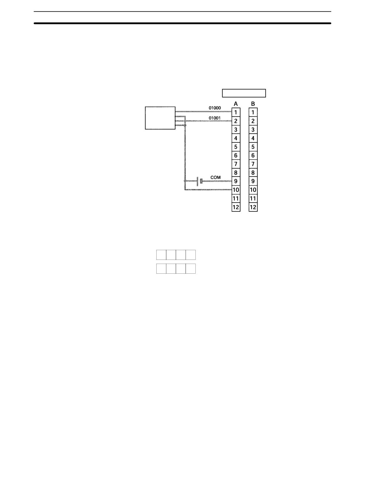
CPM2A/CPM2C Pulse Output Functions
Section
2-5
Wire the CPM2C to the motor driver as shown in the following illustration. In this
case, a CPU Unit with sinking transistor outputs is used.
Note The following examples are for Fujitsu-compatible connectors. Output bit ad-
dresses and connector pin numbers depend on the models. Refer to the CPM2C
Operation Manual (W356) or the CPM2C-S Operation Manual (W377) for de-
tails.
Output connector (See above note.)
Motor Driver
24 VDC
Note Refer to the operation manual for details on wiring.
PC Setup
15
0
DM 6629
0
Sets the coordinate system for pulse output 0 as relative.
DM 6642
0
0
High-speed counter not used.
(Set for other than synchronized pulse control.)
125
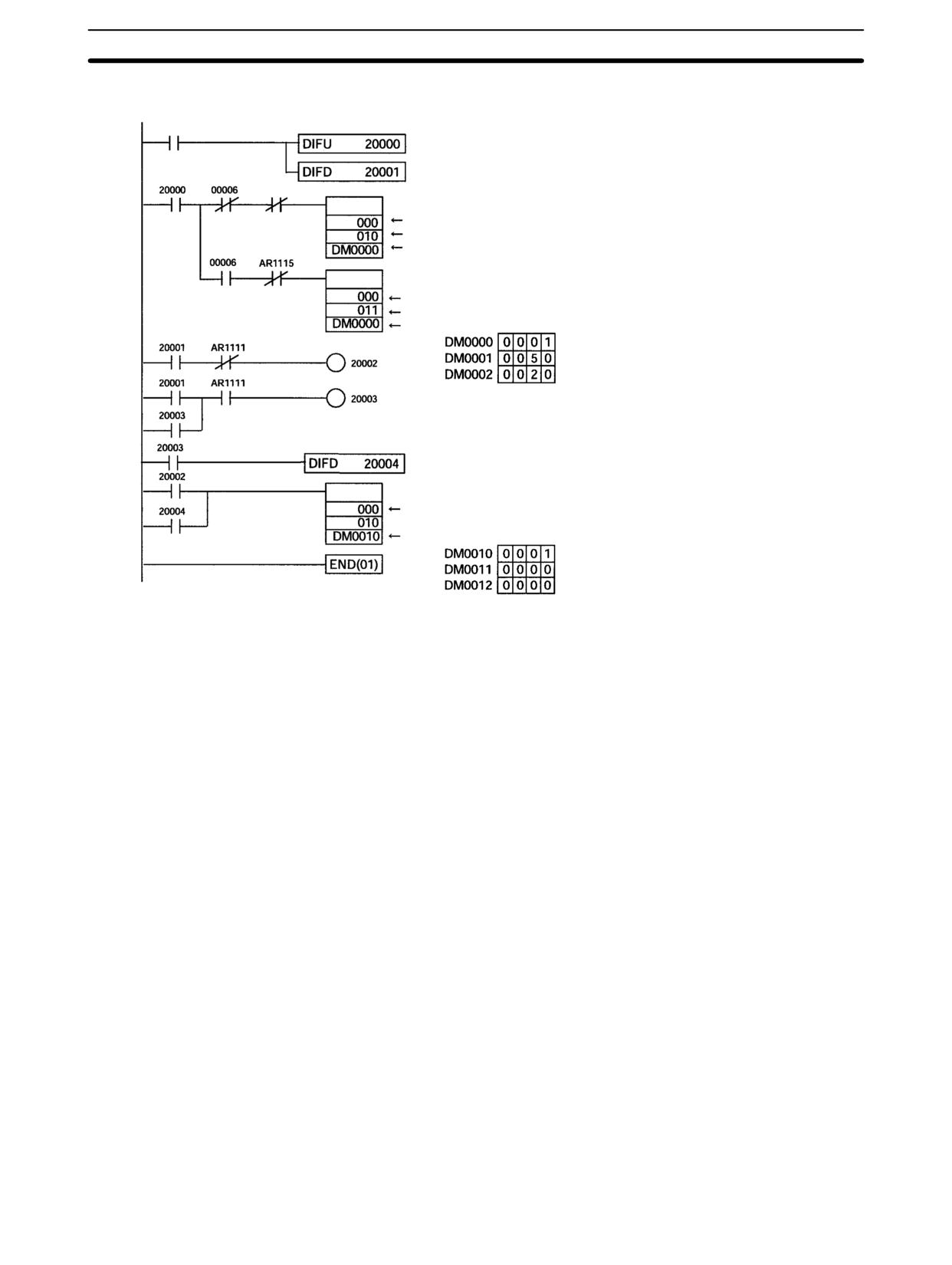
CPM2A/CPM2C Pulse Output Functions
Section
2-5
Programming
00005 (Execution condition)
(13)
Detects turning ON of execution condition.
(Direction designator)
(14)
Detects turning OFF of execution condition.
AR1115
ACC(--)
Output in CW direction
Pulse output 0
Continuous mode, up/down pulses, CW direction
(Direction designator)
Beginning word of settings table
ACC(--)
Output in CCW direction
Pulse output 0
Continuous mode, up/down pulses, CCW direction
Beginning word of settings table
Acceleration/deceleration rate: 10 Hz/10 ms
Target frequency: 500 Hz
Starting frequency: 200 Hz
(14)
ACC(--) Deceleration stop
Pulse output 0
Beginning word of settings table
Acceleration/deceleration rate: 10 Hz/10 ms
Target frequency: 0 Hz
126
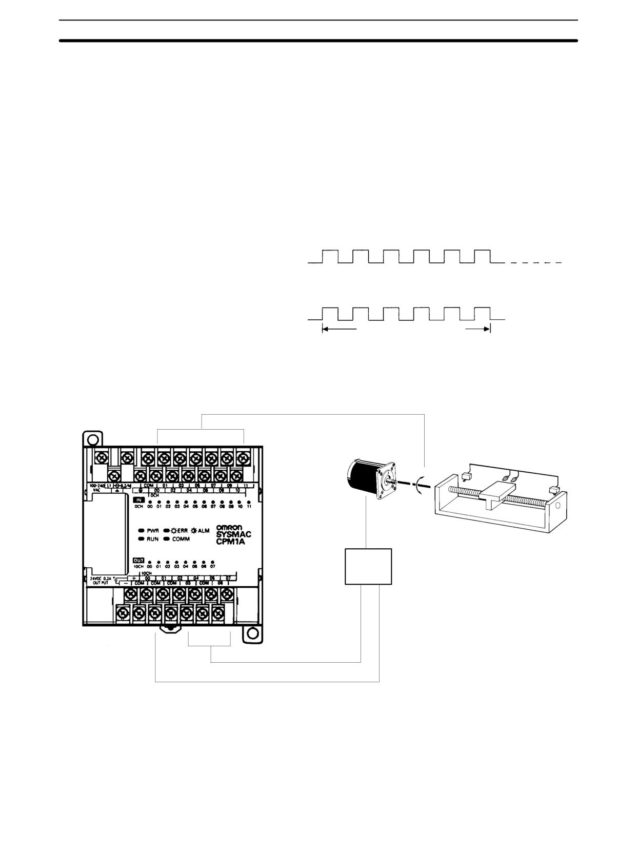
CPM1A Pulse Output Functions
Section
2-6
2-6
CPM1A Pulse Output Functions
The CPM1A PCs with transistor outputs have a pulse output function capable of
outputting a pulse of 20 Hz to 2 kHz (single-phase). Either IR 01000 or IR 01001
can be selected for pulse output, and the pulse output can be set to either the
continuous mode, under which the output can be stopped by an instruction, or
the independent mode, under which the output is stopped after a preset number
of pulses (1 to 16,777,215).
Refer to the CPM1A Operation Manual for details on hardware connections to
output points and ports.
Pulses are output at the specified frequency until stopped.
Continuous mode
Pulse output is stopped automatically when the specified
number of pulses has been output.
Independent mode
Specified number of pulses
Stepping motor
Stepping motor
Control input
Motor
controller
CW/CCW control output
Pulse output
(single-phase output)
IR 01000 or IR 01001
Note
1. The CPM1A uses a single-phase pulse output. The control signal for the
direction of rotation (CW/CCW) for the motor driver must be written in the
program.
2. Be sure to use a CPU Unit with transistor outputs.
127
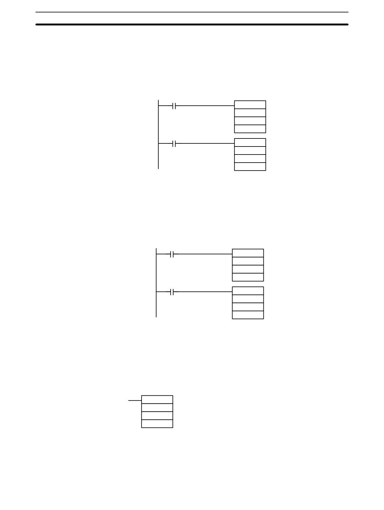
CPM1A Pulse Output Functions
Section
2-6
2-6-1
Programming Example in Continuous Mode
In this example program, pulse output begins from IR 01000 when input
IR 00004 turns ON, and is stopped when input IR 00005 turns ON.
SPED(64) can be used to stop pulse output. When using SPED(64) for that pur-
pose, specify #0000 (constant or word contents) as the pulse frequency.
00004 (pulse output condition)
@SPED(64)
Begins pulse output.
000
Output from 01000
001
Continuous mode
#0100
Pulse frequency: 1 kHz
00005 (pulse output stop condition)
@INI(61)
Stops pulse output.
000
003
000
2-6-2
Programming Example in Independent Mode
In this example program, pulse output begins from IR 01000 when input
IR 00004 turns ON, and is stopped after the specified number of pulses have
been output. The pulse amount is set in DM 0100 and DM 0101.
00004 (pulse output condition)
@PULS(65)
Sets the number of pulses.
000
000
DM 0100
Pulse number setting
00004 (pulse output condition)
@SPED(64)
Begins pulse output.
000
000
Independent mode
#0100
Pulse frequency: 1 kHz
2-6-3
Using Pulse Output Instructions
Setting the Number of
Before beginning pulse output using the independent mode use PULS(65) as
Pulses
shown below to set the number of pulses to be output. This setting is not required
for the continuous mode.
@PULS(65)
000
000
N
In N, set the beginning word address of the words where the number of pulses is
set. Store the number of pulses in words N and N+1, in eight digits BCD, with the
leftmost four digits in N+1 and the rightmost four digits in N.
Make the setting within a range of 00000001 to 16777215 (BCD).
128
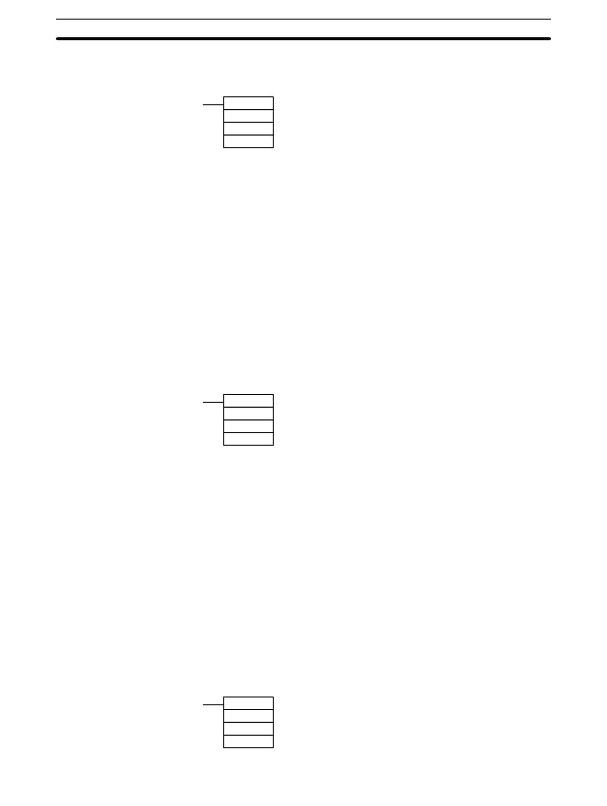
CPM1A Pulse Output Functions
Section
2-6
Beginning Pulse Output
With SPED(64), set the bit location for pulse outputs (IR 01000 or IR 01001), the
output mode (independent, continuous), and the pulse frequency to begin the
pulse output.
@SPED(64)
P
M
F
P (3 digits BCD)
000: Outputs to IR 01000
010: Outputs to IR 01001
M (3 digits BCD)
000: Independent mode
001 Continuous mode
F (4 digits BCD)
For the beginning pulse output frequency, specify a
constant or word contents. The specified value and set
frequency are as follows:
Specified value:
0002 to 0200
Set frequency:
20 to 2,000 Hz
Note
1. Pulses can be output from only one bit at a time.
2. When pulse output is begun in independent mode, the number of pulses is
read when SPED(64) is executed. PULS(65) cannot be used to change the
number of pulses while pulses are being output.
2-6-4
Changing the Frequency
To change the frequency during pulse output, change the frequency setting with
SPED(64). At that time, set the operands other than the frequency to the same
settings as at the beginning of pulse output.
@SPED(64)
P
M
F
P (3 digits BCD)
Same as at beginning of pulse output.
M (3 digits BCD)
Same as at beginning of pulse output.
F (4 digits BCD)
For the changed pulse output frequency, specify a
constant or word contents. The specified value and set
frequency are as follows:
Specified value:
0002 to 0200
Set frequency:
20 to 2,000 Hz
2-6-5
Stopping Pulse Output
When pulses are output in the independent mode, the pulse output will automati-
cally stop after the number of pulses specified with PULS(65) has been output.
When pulses are output in the continuous mode, either of the following two
methods can be used to stop the pulse output.
1. Use SPED(64) to set the frequency to 0.
2. Use INI(61) to stop the pulse output.
Using SPED(64)
The first method is to use SPED(64) to stop the pulse output by setting the fre-
quency to 0. For details, refer to 2-6-4 Changing the Frequency.
Using INI(61)
The second method is to use INI(61) to stop the pulse output, as follows:
@INI(61)
000
003
000
129
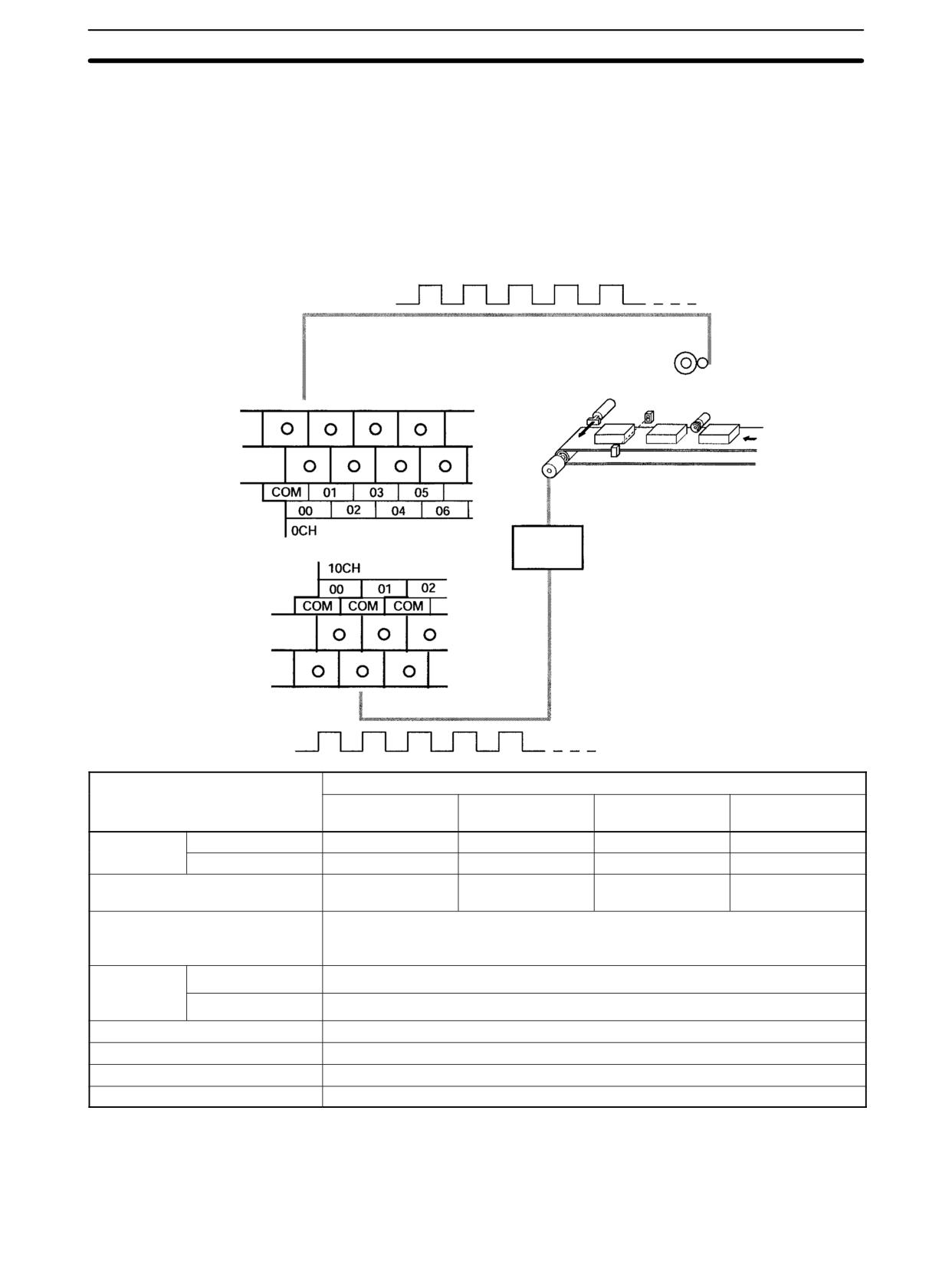
Synchronized Pulse Control (CPM2A/CPM2C Only)
Section
2-7
2-7
Synchronized Pulse Control (CPM2A/CPM2C Only)
By combining the CPM2A/CPM2C’s high-speed counter function with the pulse
output function, the output pulse frequency can be controlled as a specified mul-
tiple of the input pulse frequency.
Note A CPU Unit with transistor outputs is required in order to use synchronized pulse
control, i.e., either a CPM2A-jjCDT-D or CPM2A-jjCDT1-D.
The following diagram shows the configuration for a CPM2A, but the configura-
tion for a CPM2C is identical.
Counter input
Pulse input 00000
or 00001
Main motor
Rotary encoder
Motor
driver
Pulse output 01000 or 01001
(single-phase output)
Item
Input mode
Differential phase
Pulse + direction
Up/down pulse
Increment mode
input mode
input mode
input mode
Input
00000
Phase-A input
Count input
CW input
Count input
numb
er
00001
Phase-B input
Direction input
CCW input
(See note 1.)
Input method
Differential phase
Single-phase input
Single-phase input
Single-phase input
input (4X)
Input frequency range
10 to 500 Hz (accuracy ±1 Hz)
20 Hz to 1 kHz (accuracy ±1 Hz)
300 Hz to 20 kHz (accuracy ±25 Hz) (See note 2.)
Output
01000
Pulse output 0
number (See
note 3.)
01001
Pulse output 1
Output method
Single-phase output
Output frequency range
10 Hz to 10 kHz (accuracy 10 Hz)
Frequency ratio
1% to 1,000% (Can be specified in units of 1%.)
Synchronized control cycle
10 ms
Note
1. Can be used as an ordinary input.
2. When 10 kHz or less, then the accuracy is ±10 Hz.
3. Either can be selected as the output number, using SYNC(--).
130
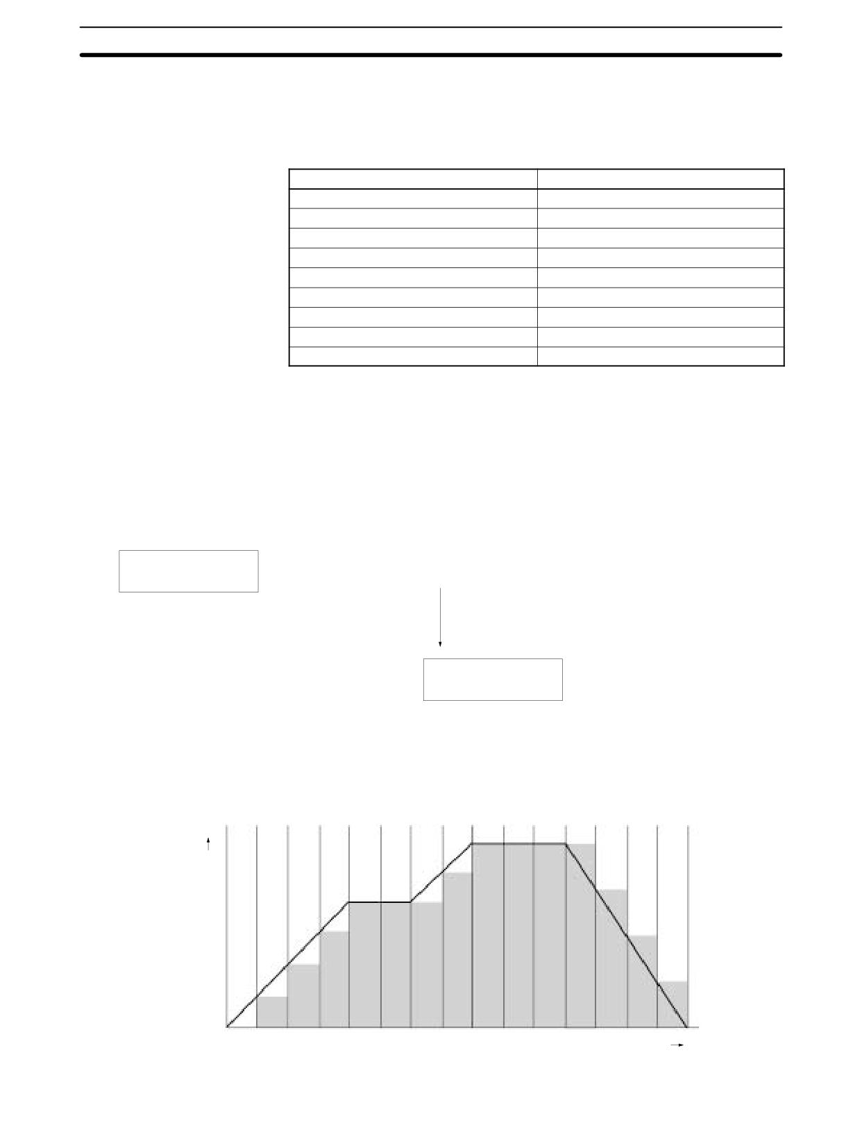
Synchronized Pulse Control (CPM2A/CPM2C Only)
Section
2-7
The directions of pulse inputs are all ignored. The frequency of a pulse that has
been input is read, without regard to the direction.
The following table shows the relationships between synchronized pulse control
and the CPM2A’s other functions.
Function
Synchronized pulse control
Synchronized pulse control
---
Interrupt inputs
Can be used simultaneously.
Interval timer interrupts
Can be used simultaneously.
High-speed counters
Cannot be used simultaneously.
Interrupt inputs (counter mode)
Can be used simultaneously.
Pulse outputs
Cannot be used simultaneously.
Quick-response inputs
Can be used simultaneously.
Input time constant
See note.
Clock
Can be used simultaneously.
Note When inputs 00000 and 00001 are set for use as synchronized pulse control in-
puts, the input time constant settings for the affected inputs are disabled. The
input time constants remain in effect, however, for the values for refreshing the
relevant input data area.
The relationship between the pulse input frequency and the pulse output fre-
quency is shown below.
Pulse input frequency
X
Frequency ratio
=
Rough pulse output frequency
Values are rounded off in units of 10 Hz.
10 to 500 Hz
A value less than 10 Hz is regarded as 0 Hz.
20 Hz to 1 kHz
A value greater than 10 kHz is regarded as 10 kHz.
300 Hz to 20 kHz
Pulse output frequency
(10 Hz to 10 kHz)
The scaling factor control cycle is 10 ms, and the pulse output frequency is
changed at intervals of 10 ms with respect to the pulse input frequency.
Frequency
Time
131
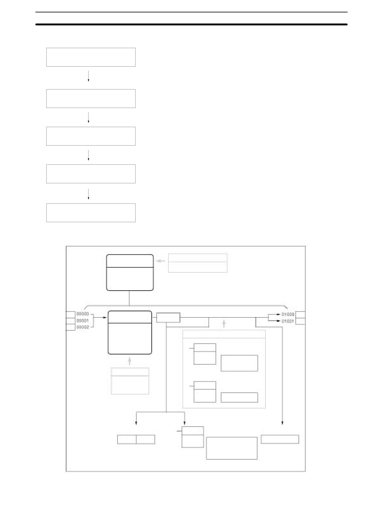
Synchronized Pulse Control (CPM2A/CPM2C Only)
Section
2-7
Using Synchronized Pulse Control
Differential phase pulse input mode, pulse + direction input
Select the input mode.
mode, up/down pulse input mode, increment mode
Select the pulse synchronization
Input frequency: 10 Hz to 500 Hz; 20 Hz to 1 kHz; 300 Hz to 20 kHz
input frequency.
Input numbers: 00000, 00001, and 0002
Wire the inputs and outputs.
Output numbers: 01000 and 01001
PC Setup (DM 6642)
Settings for synchronized pulse control: Input mode, input frequency
SYNC(--): For beginning synchronized pulse control and changing the scaling factor.
Create a ladder diagram program.
INI(61): For stopping synchronized pulse control.
PRV(62): For reading the high-speed counter frequency and the synchronized pulse
control status.
PC Setup
Synchronized
pulse control
DM 6642, bits 08 to 15
10 Hz to 500 Hz
20 Hz to 1 kHz
300 Hz to 20 kHz
Either
Encoder
Pulse output 0
Input mode
Count
inputs
Pulse output 1
Differential phase input
Pulse + direction input
Ladder diagram program
Up/down input
SYNCHRONIZED
SYNC(--)
PULSE CONTROL
Increment input
instruction
Start synchronized
pulse control
Change scaling
factor
PC Setup
DM 6642, bits
MODE CONTROL
00 to 03
INI(61)
instruction
Stop synchronized
pulse control
Every scan
Immediately
Every scan
HIGH-SPEED
COUNTER PV
Synchronized pulse
Counter frequency PV
PRV(62) READ instruction
control status
SR 249
SR 248
Read high-speed counter
AR 1100 to AR 1107
frequency
Read synchronized pulse
control status
The pulse output frequency cannot be read.
132
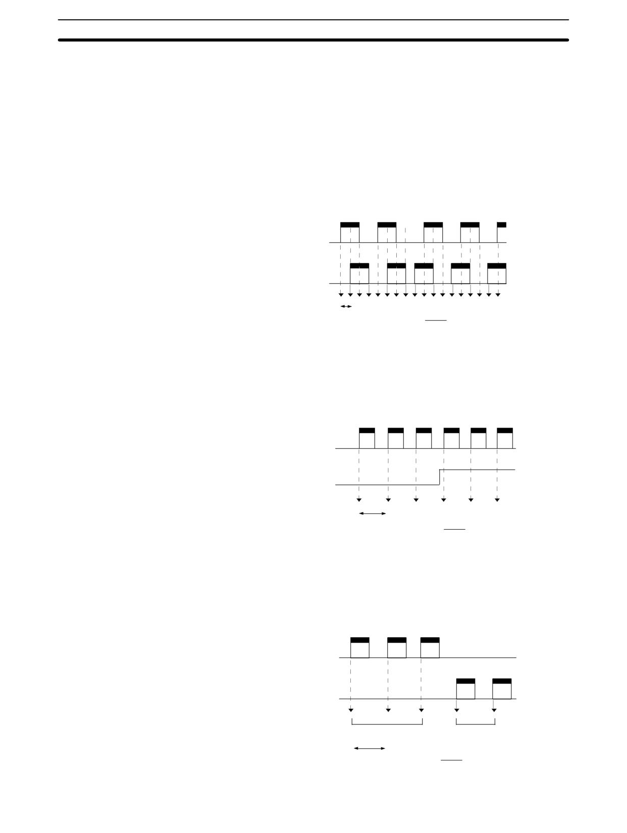
Synchronized Pulse Control (CPM2A/CPM2C Only)
Section
2-7
Selecting the Input Mode
Select the differential phase input mode, the pulse + direction input mode, the
up/down pulse input mode, or the increment mode. These modes are explained
below.
Select one of the following as the input frequency range: 10 Hz to 500 Hz, 20 Hz
Selecting the Pulse
Synchronization Input
to 1 kHz, or 300 Hz to 20 kHz. For more information on input frequencies, refer to
Frequency
the following diagrams.
Differential Phase Input Mode
In the differential phase input mode, the count is incremented or decremented
according to two differential phase signals (phase A and phase B) with a multi-
plication factor of 4.
ON
Phase A
OFF
ON
Phase B
OFF
1,000
Nms → Frequency =
N
Pulse + Direction Input Mode
In the pulse + direction input mode, pulse signals and direction signals are input,
and the count is incremented or decremented according to the direction signal
status.
ON
Pulse inputs
OFF
ON
Direction
inputs
OFF
1,000
Nms → Frequency =
N
Up/Down Pulse Input Mode
In the up/down pulse input mode, CW signals (up pulses) and CCW signals
(down pulses) are input, and the count is incremented or decremented accord-
ingly.
ON
CW inputs
OFF
ON
CWW inputs
OFF
Incremented
Decremented
1,000
Nms → Frequency =
N
133
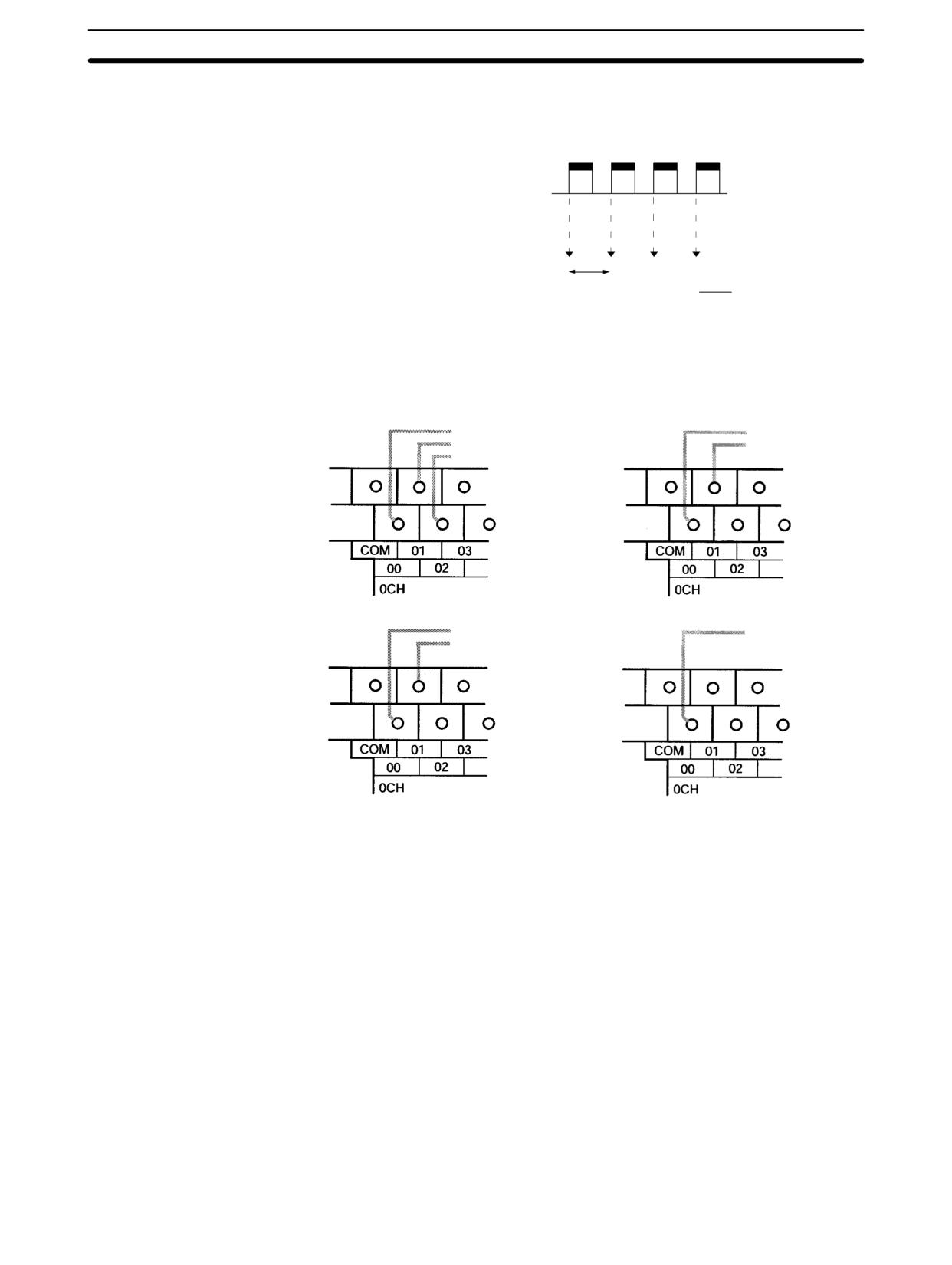
Synchronized Pulse Control (CPM2A/CPM2C Only)
Section
2-7
Increment Mode
In the increment mode, pulse signals are input and the count is incremented with
each pulse. Phase-B inputs can be used as ordinary inputs.
ON
Pulse inputs
OFF
1,000
Nms → Frequency =
N
Wiring the Inputs
Input Wiring
Wire the CPM2A inputs as shown in the following diagram.
Differential Phase Input Mode
Up/Down Pulse Input Mode
00000: Phase-A input
00000: CW input
00001: Phase-B input
00001: CCW input
00002: Phase-Z input
Pulse + Direction Input Mode
Increment Mode
00000: Pulse input
00000: Pulse input
00001: Direction input
134
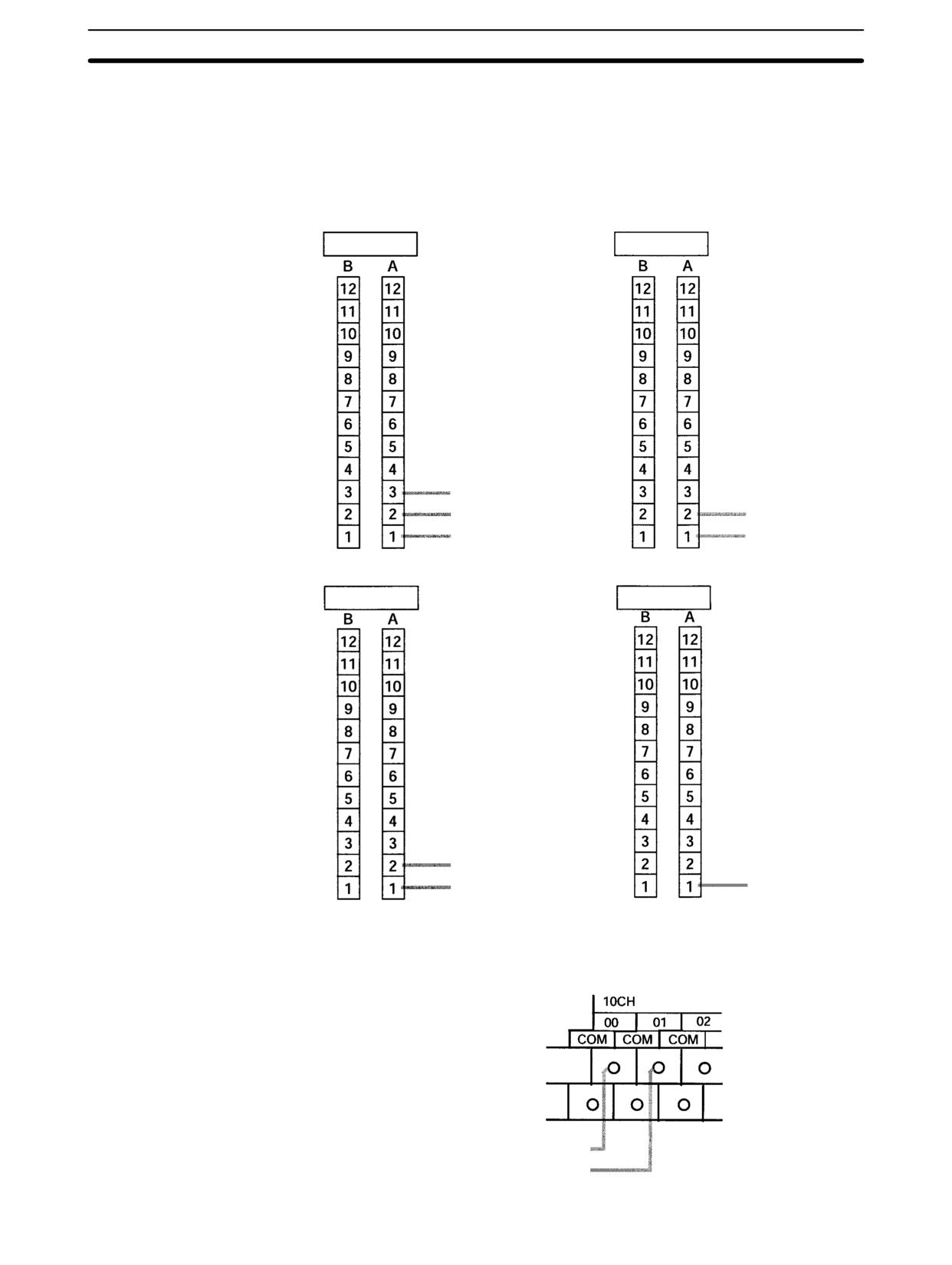
Synchronized Pulse Control (CPM2A/CPM2C Only)
Section
2-7
Wire the CPM2C inputs as shown in the following diagram.
Note The following examples are for Fujitsu-compatible connectors. Input bit ad-
dresses and connector pin numbers depend on the models. Refer to the CPM2C
Operation Manual (W356) or the CPM2C-S Operation Manual (W377) for de-
tails.
Differential Phase Input Mode
Up/Down Pulse Input Mode
Input connector
(See above note.)
Input connector
(See above note.)
00002: Phase-Z input
00001: Phase-B input
00001: CCW input
00000: Phase-A input
00000: CW input
Pulse + Direction Input Mode
Increment Mode
Input connector
(See above note.)
Input connector
(See above note.)
00001: Direction input
00000: Pulse input
00000: Pulse input
Output Wiring
Wire the CPM2A outputs as shown in the following diagram.
Output Wiring
01000: Pulse output 0
01001: Pulse output 1
135
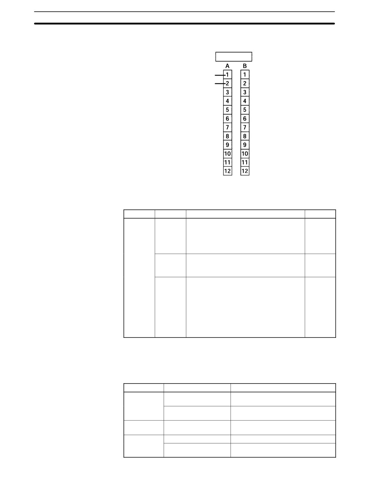
Synchronized Pulse Control (CPM2A/CPM2C Only)
Section
2-7
Wire the CPM2C outputs as shown in the following diagram.
Output connector (See above note.)
01000: Pulse output 0
01001: Pulse output 1
PC Setup
The settings in the PC Setup related to synchronized pulse control are listed in
the following table.
Word
Bits
Function
Setting
DM 6642
00 to 03
High-speed counter input mode setting
0, 1, 2, or
4
0: Differential phase input
5 kHz
1: Pulse + direction input
20 kHz
2: Up/down input
20 kHz
4: Increment
20 kHz
04 to 07
High-speed counter reset method setting
0 or 1
0: Phase-Z signal + software reset
1: Software reset
08 to 15
High-speed counter setting
02, 03, 04
00: Do not use.
01: Use as high-speed counter
02: Use as synchronized pulse control
(10 Hz to 500 Hz)
03: Use as synchronized pulse control
(20 Hz to 1 kHz)
04: Use as synchronized pulse control
(300 Hz to 20 kHz)
The settings will go into effect when the mode is changed (from PROGRAM to
MONITOR/RUN) or when the power supply is turned ON to the PC.
Ladder Diagram
The following table shows the instruction operations related to synchronized
Programming
pulse control.
Instruction
Control
Operation
(@)SYNC(--)
Start synchronized
Specifies the frequency scaling factor
control
and the output port, and outputs pulses.
Change frequency
Changes the frequency scaling factor
scaling factor
during pulse output.
(@)INI(61)
Stop synchronized
Stops the pulse outputs.
control
(@)PRV(62)
Read input frequency
Reads the input frequency.
Read synchronized
Reads the synchronized control status.
control status
136
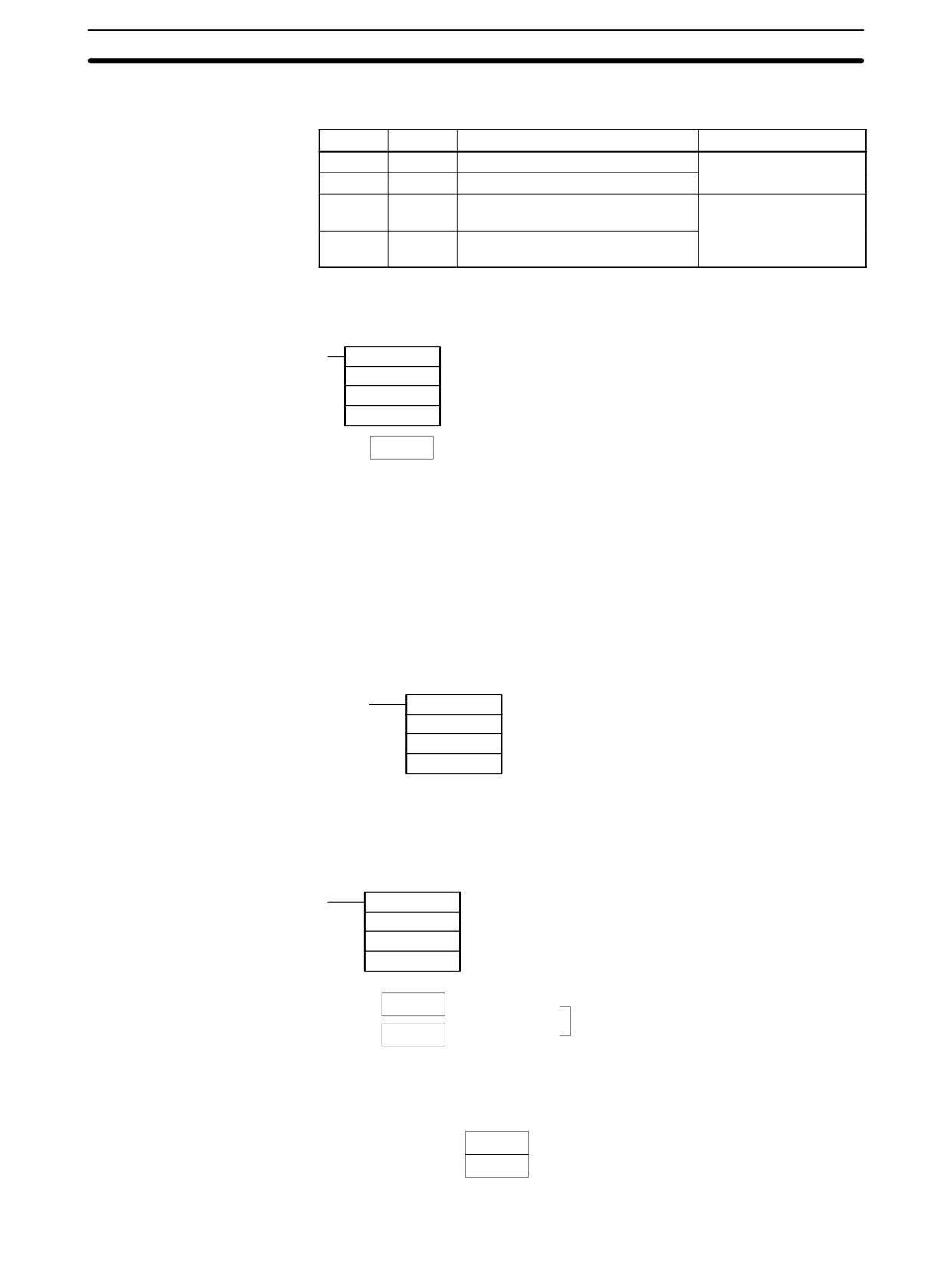
Synchronized Pulse Control (CPM2A/CPM2C Only)
Section
2-7
The following table shows the words and bits related to synchronized pulse con-
trol.
Word
Bits
Name
Contents
248
00 to 15
Input frequency PV, rightmost digits
Reads the input
frequency PV
249
00 to 15
Input frequency PV, leftmost digits
AR 11
15
Pulse output in progress for pulse
ON: Output in progress
output 0
OFF: Stopped
AR 12
15
Pulse output in progress for pulse
output 1
Start Frequency Control
This function specifies the bits for pulse outputs (01000, 01001) and the fre-
quency scaling factor (1% to 1,000%), and starts the pulse output.
(@)SYNC(--)
000
Pulse input port designation (000: High-speed counter)
P2
Pulse output port designation (000: Pulse output 0; 010: Pulse output 1)
C
Frequency scaling factor setting
C
Frequency scaling factor
Register the frequency scaling factor to be set.
#0001 to #1000 (4 digits BCD): 1 to 1,000%
Note
When using SYNC(--) to specify a frequency scaling factor, be careful to keep
the pulse output frequency below 10 kHz.
Change Frequency Scaling Factor
This function changes the frequency scaling factor during synchronized control
(during pulse output) by specifying the bits for pulse outputs (01000, 01001) and
the frequency scaling factor (1% to 1,000%) and executing SYNC(--).
Stop Synchronized Control
This function stops the pulse outputs.
(@)INI(61)
000
Port specifier (000: High-speed counter)
005
Control designation (005: Stop synchronized control)
000
Fixed: 000
Note
The pulse output can also be stopped by switching the PC to PROGRAM mode.
Read Input Frequency
This function reads the input frequency PV.
Using an Instruction
(@)PRV(62)
000
Fixed: 000
000
Control designation (000: Read high-speed counter input frequency)
D
Beginning word for storing input frequency PV
D
Rightmost 4 digits
00000000 to 00020000 (8 digits BCD)
D+1
Leftmost 4 digits
Using Data Areas
As shown in the following illustration, the input frequency is stored in words 248
and 249.
Word 248
Input frequency PV (Rightmost)
Word 249
Input frequency PV (Leftmost)
137
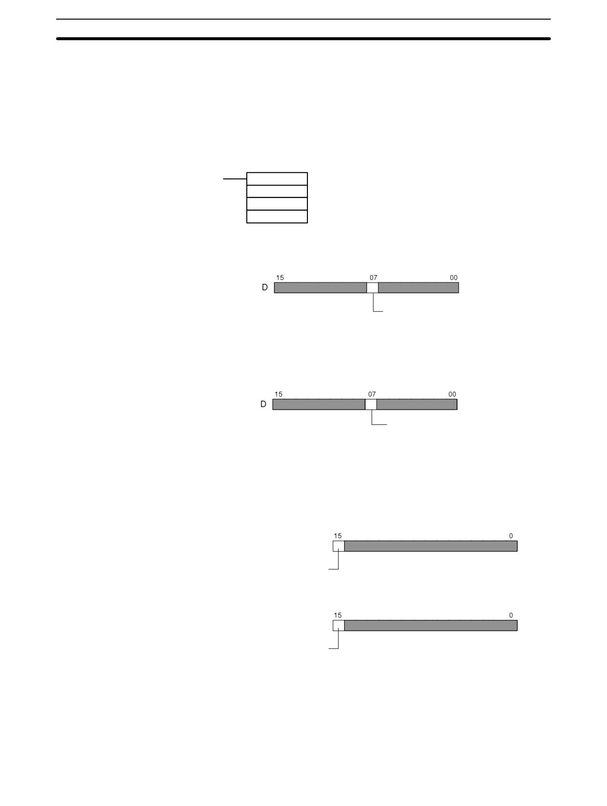
Synchronized Pulse Control (CPM2A/CPM2C Only)
Section
2-7
Words 248 and 249 are refreshed with every scan, so there may be a discrepan-
cy from the exact PV at any given time.
When the PV is read by executing PRV(62), words 248 and 249 are refreshed
with the same timing.
Read Synchronized Control Status
This function reads the synchronized control status.
Using an Instruction
(@)PRV(62)
000
Port specifier (000: Pulse output 0; 010: Pulse output 1)
001
Control designation (001: Read synchronized control status)
D
Beginning word for storing synchronized control status
• Port specifier: 000
Status of pulse output 0
0: Stopped
1: Pulse output in progress
• Port specifier: 010
Status of pulse output 1
0: Stopped
1: Pulse output in progress
Using Data Areas
As shown in the following illustration, the status of pulse output 0 is stored in
AR 1115, and the status of pulse output 1 is stored in AR 1215.
AR 11
Status of pulse output 0
0: Stopped
1: Output in progress
AR 12
Status of pulse output 1
0: Stopped
1: Output in progress
AR 1115 and AR 1215 are refreshed once each cycle, so there may be a discrep-
ancy from the exact PV at any given time.
When the PV is read by executing PRV(62), AR 1112 and AR 1212 are refreshed
immediately.
138
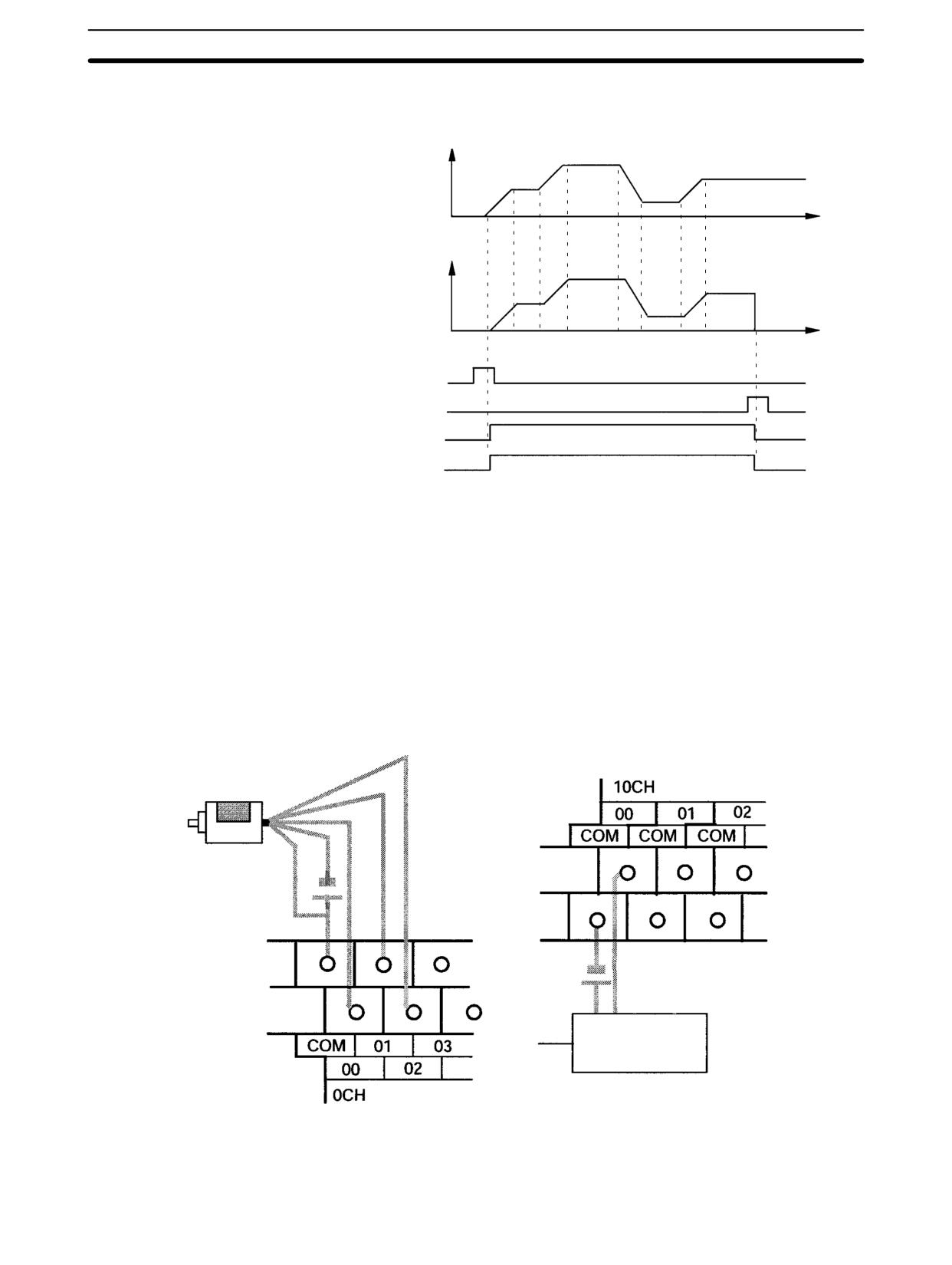
Synchronized Pulse Control (CPM2A/CPM2C Only)
Section
2-7
Relationship Between Status and Operation
Frequency
Input pulses
Time
Frequency
Output pulses
Time
SYNC(--) execution
INI(61) execution
Output 0 in progress
Output 1 in progress
Application Example
Explanation
In this example, when the execution condition (00005) turns ON, synchronized
pulse control is started and pulses are output from output 01000 (pulse output 0)
according to the pulses input by the high-speed counter. At this time, the fre-
quency scaling factor can be changed by means of analog control 0. When the
execution condition (00005) turns OFF, synchronized pulse control is stopped.
Wiring
Wire the CPM2A as shown in the following illustration.
Orange
White
Black
Blue
Rotary encoder
Brown
Motor driver
Wire the CPM2C as shown in the following illustration. In this case, a CPU Unit
with sinking transistor outputs is used.
139
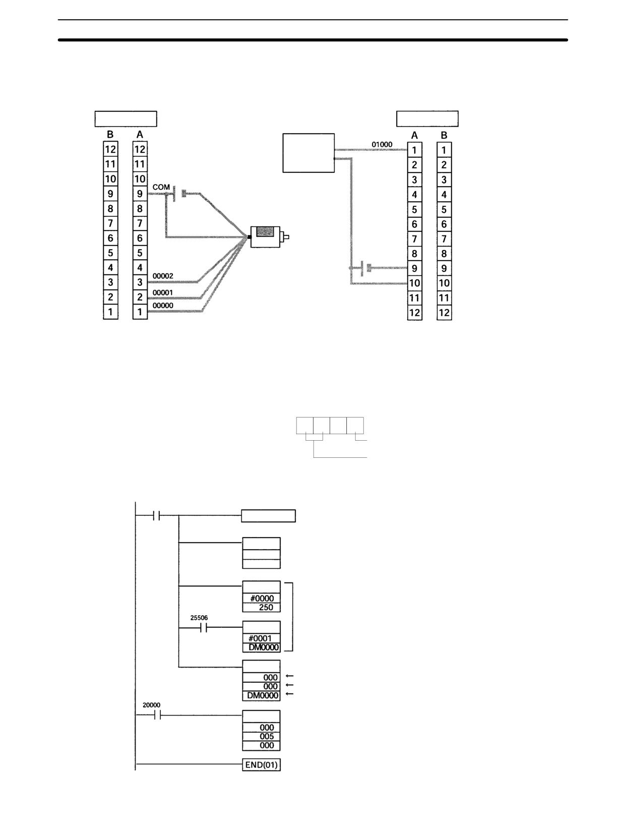
Synchronized Pulse Control (CPM2A/CPM2C Only)
Section
2-7
Note The following examples are for Fujitsu-compatible connectors. I/O bit addresses
and connector pin numbers depend on the models. Refer to the CPM2C Opera-
tion Manual (W356) or the CPM2C-S Operation Manual (W377) for details.
Input connector
(See above note.)
Output connector
(See above note.)
Motor Driver
Blue
Rotary encoder
Brown
COM
Orange
24 VDC
White
Black
Note For details regarding motor driver wiring to outputs and rotary encoder wiring to
inputs, refer to the CPM2A Operation Manual (W352)/CPM2C (W356) Opera-
tion Manual CPM2C-S Operation Manual (W377).
PC Setup
15
0
DM 6642
0
2
0
0
0: Differential phase input
02: Use as pulse synchronization output.
Programming (Example for CPM2A)
00005 (Execution condition)
Detects the turning OFF of the execution condition.
DIFD(14) 20000
MOV(21)
250
Moves the value of analog control 0 into DM 0000.
DM0000
CMP(20)
Sets DM 0000 to “1” when analog control 0 is set
to “0.”
MOV(21)
(The analog controls are built into the CPM2A
PCs, but not CPM2C PCs.)
SYNC(--) SYNCHRONIZED PULSE CONTROL execution
HIgh-speed counter
Pulse output port 0
Beginning word of frequency scaling factor
INI(61) Stops synchronized pulse control.
140
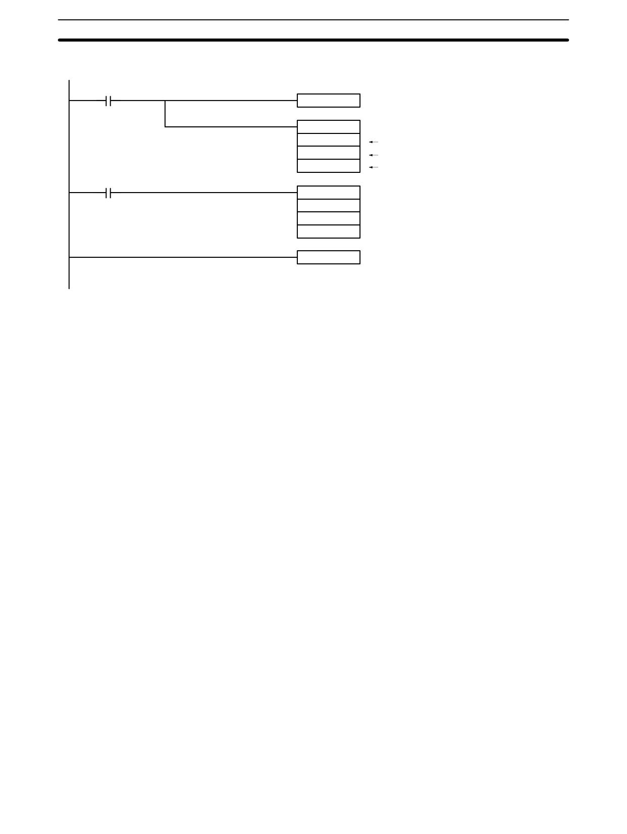
Synchronized Pulse Control (CPM2A/CPM2C Only)
Section
2-7
Programming (Example for CPM2C)
Execution condition
00005
DIFD (14)
20000
Detects OFF to ON transition in execution condition.
SYNC
Executes synchronized pulse control.
000
High-speed counter
000
Pulse output 0
DM0000
First word containing frequency factor
20000
INI
Stops synchronized pulse control.
000
005
000
END (01)
141
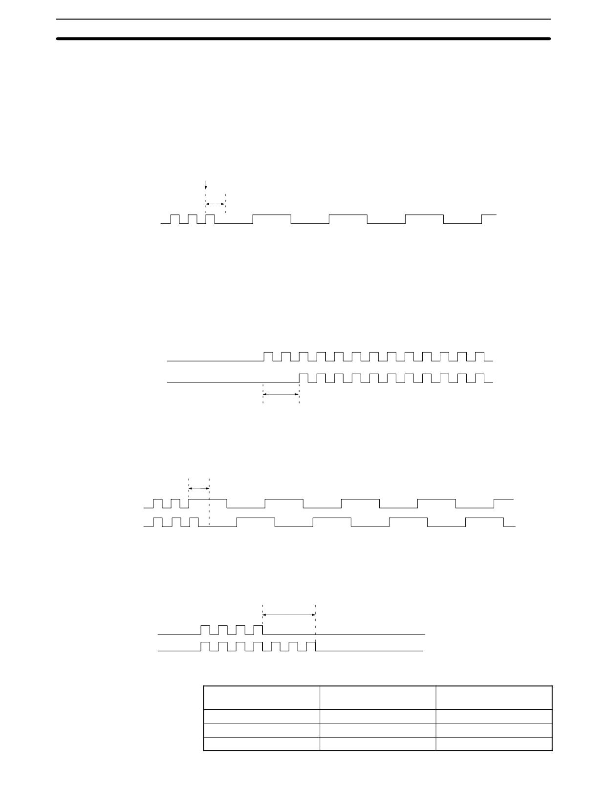
Data Computation Standards
Section
2-8
2-8
Data Computation Standards
The degree of error and performance in pulse outputs and synchronized pulse
control are described in this section.
2-8-1
Pulse Outputs
Delays in Frequency
There will be a delay before a change in the frequency during pulse output is
Changes
actually applied to the output, as shown below.
Frequency
changed
Delay
Pulse output
Maximum delay (ms) = One period of the current pulse output
2 + 10 + instruction execution time
There will be an error between the frequency of the output pulse and the set fre-
Frequency Error
quency of less than ± 1% due to internal processing error.
2-8-2
Synchronized Pulse Control
Delay in Start of Pulse
The following diagram shows the delay that will occur between starting synchro-
Output
nized pulse control and the start of actual pulse output.
Pulse input
Pulse output
Delay
Maximum delay (ms) = One period of the pulse input x 2 + 16.25
Delays in Frequency
There will be a delay before a change in the frequency during pulse output is
Changes
actually applied to the output when performing synchronized pulse control, as
shown below.
Delay
Pulse input
Pulse output
Maximum delay (ms) = One period of the current pulse output
2 + 10
Delay in Stop of Pulse
The following diagram shows the delay that will occur between stopping syn-
Output
chronized pulse control (0 Hz) and the end of actual pulse output during synchro-
nized pulse control.
Delay
Pulse input
Pulse output
Maximum delay (ms) = Setting in DM 6642 (see below) + One period of the current pulse output B 2 + 10
Setting of
Frequency range
Delay
DM 6642 bits 08 to 15
02
10 to 500 Hz
262 ms
03
20 Hz to 1 kHz
66 ms
04
300 Hz to 20 kHz
4 ms
142
CompoBus/S I/O Slave Functions (CPM1A/CPM2A/CPM2C Only)
Section
2-11
There will be an error between the frequencies of the input pulse and output
Frequency Error
pulse, as described below. The error consists of error in the input pulse frequen-
cy measurement and error in the output pulse frequency.
Input Pulse Frequency Measurement Error
The error in measuring the frequency of the input pulse depends on the setting in
DM 6642, as shown below. If a multiplication factor is specified for synchronized
pulse control, the error given in the table must also be multiplied by the same
factor.
Setting of
Frequency range
Error
DM 6642 bits 08 to 15
02
10 to 500 Hz
±1 Hz
03
20 Hz to 1 kHz
±1 Hz
04
300 Hz to 20 kHz
±10 Hz
Output Pulse Frequency Error
There will be an error between the frequency of the output pulse and the set fre-
quency of less than ± 1% due to internal processing error.
Example
DM 6642 bits 08 to 15:
4 (frequency range: 300 Hz to 20 kHz)
Multiplication factor:
300%
Input frequency:
1 kHz (error: 0%)
If synchronized pulse control is performed under the above conditions, there will
be an error of ±10 Hz in measuring the frequency range of the input pulse. The
input frequency will thus be 990 to 1010 Hz. The multiplication factor of 300%,
however, would make this 2970 to 3030 Hz. There would also be an error of ±1%
in the frequency of the output pulse, so the output would be in the range 2940 to
3060 Hz.
2-9
Analog I/O Functions (CPM1/CPM1A/CPM2A/CPM2C Only)
One or more Analog I/O Units can be connected to the PC to provide analog I/O.
One Analog I/O Unit allows 2 analog inputs and 1 analog output. See 3-1 Analog
I/O Units for details.
2-10
Temperature Sensor Input Functions
(CPM1A/CPM2A/CPM2C Only)
Temperature Sensor Units can be added to directly input temperature sensor
inputs into the PC. Temperature Sensor Units are available for either thermo-
couple or platinum resistance thermometer inputs.
For the CPM1A or CPM2A, up to three CPM1A-TS001/101 Temperature Sensor
Units or one CPM1A-TS002/102 Temperature Sensor Unit can be connected.
Up to 6 temperature inputs are possible for one PC.
For the CPM2C, up to four CPM2C-TS001/101 Temperature Sensor Units can
be connected, enabling up to 8 temperature inputs for one PC.
Up to three Units can be connected for the CPM2C-S.
2-11
CompoBus/S I/O Slave Functions
(CPM1A/CPM2A/CPM2C Only)
The PC can function as a Slave to a CompoBus/S Master Unit (or SRM1 Compo-
Bus/S Master Control Unit) when a CompoBus/S I/O Link Unit is connected. See
3-3 CompoBus/S I/O Link Unit for details.
143
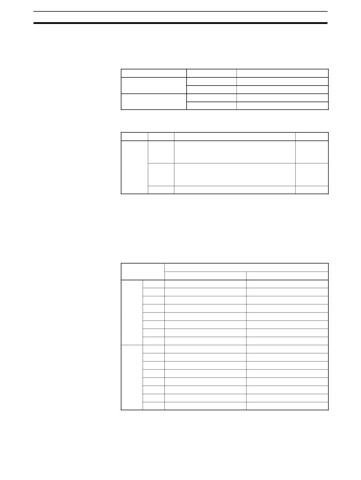
CompoBus/S I/O Master Functions (SRM1(-V2) and CPM2C-S Only)
Section
2-12
2-12
CompoBus/S I/O Master Functions (SRM1(-V2) and
CPM2C-S Only)
Maximum Number of Nodes
A maximum of either 16 or 32 CompoBus/S nodes may be connected.
Communications mode
No. of nodes set
Communications response time
High-speed mode
16
0.5 ms
32
0.8 ms
Long-distance mode
16
4.0 ms
32
6.0 ms
The communications mode and maximum number of nodes are set in the PC
Setup, as shown in the following table.
Word
Bit(s)
Function
Setting
DM 6603
00 to 03
Maximum number of CompoBus/S nodes
0 or 1
0: 32 nodes
1: 16 nodes
04 to 07
CompoBus/S communications mode
0 or 1
0: High-speed communications
1: Long-distance communications
08 to 15
Not used.
00
Note
When changes are made to these settings, always turn the power off and on
again to make the new setting effective.
Slave Interrupts
Input bits in IR 000 to IR 007 and output bits in IR 010 to IR 017 are used as inter-
rupts for CompoBus/S I/O Terminals. The CompoBus/S I/O Terminal interrupts
(IN 0 to 15 and OUT 0 to 15) are allocated as indicated in the following table.
IN0 to IN15 are the node addresses for the Input Terminals and OUT0 to OUT15
are the node addresses for the Output Terminals.
Word
Bit
15
14
13
12
11
10
9
8
7
6
5
4
3
2
1
0
Input
IR 000
IN1
IN0
IR 001
IN3
IN2
IR 002
IN5
IN4
IR 003
IN7
IN6
IR 004
IN9
IN8
IR 005
IN11
IN10
IR 006
IN13
IN12
IR 007
IN15
IN14
Output
IR 010
OUT1
OUT0
IR 011
OUT3
OUT2
IR 012
OUT5
OUT4
IR 013
OUT7
OUT6
IR 014
OUT9
OUT8
IR 015
OUT11
OUT10
IR 016
OUT13
OUT12
IR 017
OUT15
OUT14
Note
1. When the maximum number of CompoBus/S nodes is set to 16, IN8 to IN15
can be used as work bits.
2. CompoBus/S Terminals with less than 8 points are allocated bit addresses
from either 0 or 8.
144
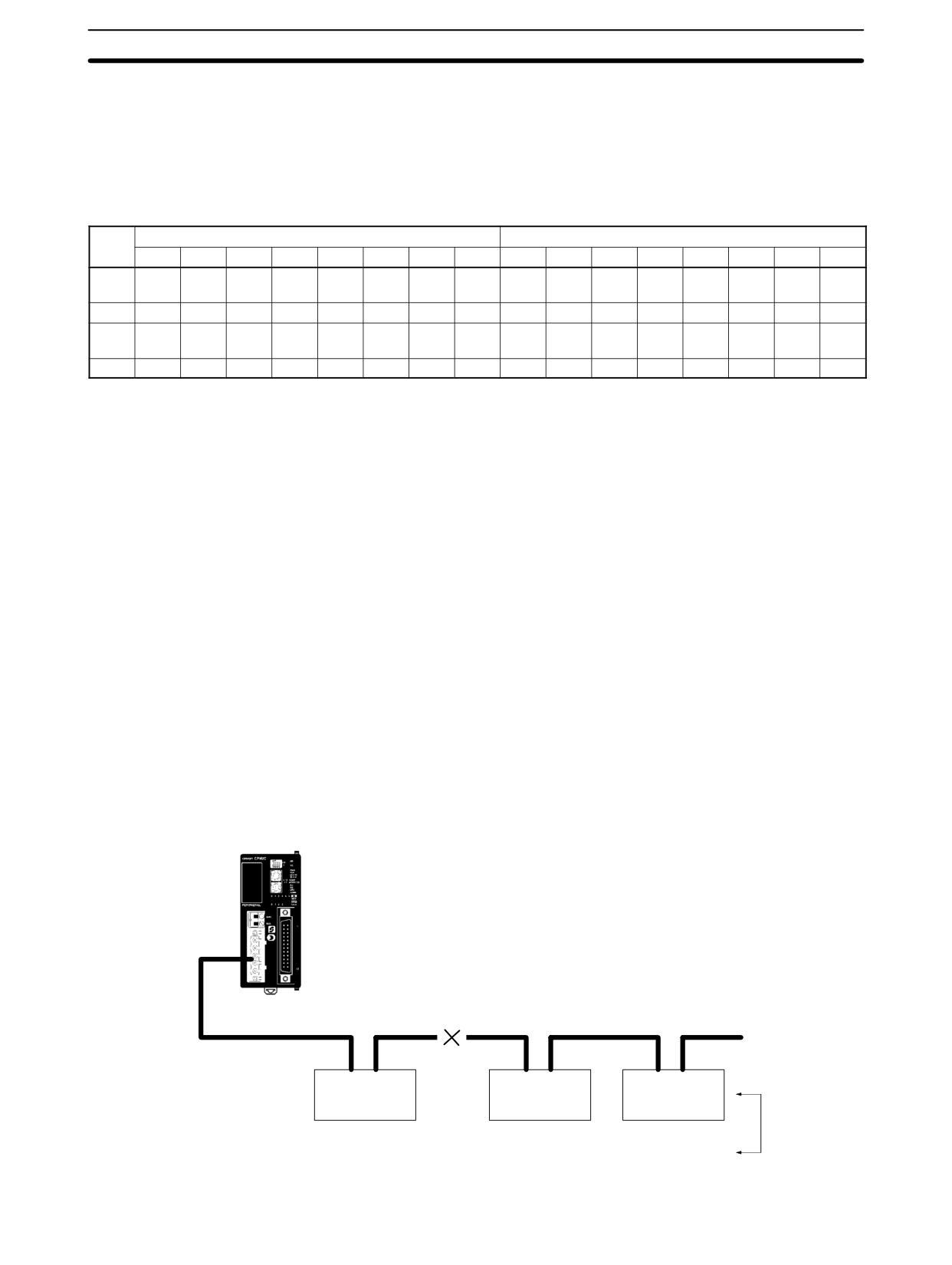
CompoBus/S I/O Master Functions (SRM1(-V2) and CPM2C-S Only)
Section
2-12
3. CompoBus/S Terminals with 16 points can be set for only even number ad-
dresses.
4. Analog Terminals can be set for only even number addresses.
Status Flags
The communications status between CompoBus/S terminals is output through
AR04 to AR07 Slave Add Flags and Slave Communications Error Flags.
Word
Uppermost bits: Slave Communications Error Flags
Lower Bits: Slave Add Flags
15
14
13
12
11
10
9
8
7
6
5
4
3
2
1
0
AR04
OUT
OUT
OUT
OUT
OUT
OUT
OUT
OUT
OUT
OUT
OUT
OUT
OUT
OUT
OUT
OUT
7
6
5
4
3
2
1
0
7
6
5
4
3
2
1
0
AR05
IN7
IN6
IN5
IN4
IN3
IN2
IN1
IN0
IN7
IN6
IN5
IN4
IN3
IN2
IN1
IN0
AR06
OUT
OUT
OUT
OUT
OUT
OUT
OUT
OUT
OUT
OUT
OUT
OUT
OUT
OUT
OUT
OUT
15
14
13
12
11
10
9
8
15
14
13
12
11
10
9
8
AR07
IN15
IN14
IN13
IN12
IN11
IN10
IN9
IN8
IN15
IN14
IN13
IN12
IN11
IN10
IN9
IN8
Note
1. IN0 to IN15 are the input terminals and OUT0 to OUT15 are the output termi-
nals.
2. When the maximum number of CompoBus/S units is set to 16, IN8 to IN15
and OUT8 to OUT15 cannot be used.
3. The Slave Add Flag turns ON when a slave joins the communications. When
the power to the CPU Unit is turned OFF and ON again all bits will turn OFF.
4. The Slave Communications Error Flag turns ON when a slave participating
in the network is separated from the network. The bit will turn OFF when the
slave re-enters the network.
5. For the SRM1, an error will not occur even if the same node address is allo-
cated to more than one slave. Errors will also not occur when communica-
tions go down or communications errors, such as broken lines, occur. Set all
node addresses very carefully and confirm slave operation by including a
section of ladder program using the Status Flags. An example is shown be-
low.
Example
SRM1 (-V2)
or CPM2C-S
CompoBus/S
Disconnection (2)
communications path
IR 000
IR 001
IR 000
Bits 00 to 07
Bits 00 to 07
Bits 00 to 07
Node address
Slave 1
Slave 2
Slave 3
duplication (1)
Node 0 (IN0)
Node 2 (IN2)
Node 0 (IN0)
145
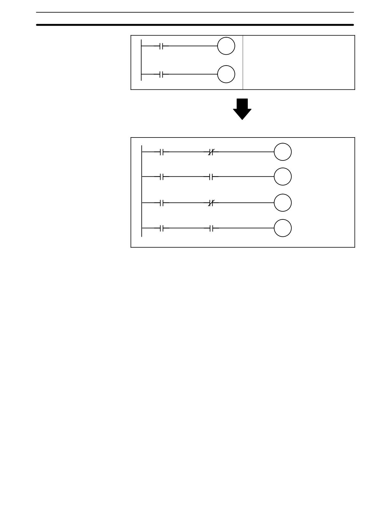
Analog Controls (CPM1/CPM1A/CPM2A Only)
Section
2-13
00000
(Slave 1 input)
If the addresses for Slave 1 and Slave 3
20000
are the same, the Master will not be able
to read input from Slave 3.
If a communications error is generated,
00100
(Slave 2 input)
the status of IR 00100 will be the same
20100
as before the error and so the change in
the status of the actual input will not be
detected.
• Example of Countermeasure in Ladder Program
AR0500
AR0508
(IN0’s
Active Flag)
(IN0’s Error Flag)
02800
(Slave 1 communications normal)
00000
02800
20000
AR0502
AR0510
(IN2’s
Active Flag)
(IN2’s Error Flag)
02900
(Slave 2 communications normal)
00100
02900
20100
2-13
Analog Controls (CPM1/CPM1A/CPM2A Only)
The PCs are equipped with analog controls that automatically transfer the set-
tings on the CPU Unit’s adjustment switches to words in the CPU Unit’s I/O me-
mory. This function is very useful when there are set values that need to be pre-
cisely adjusted during operation. These set values can be changed just by turn-
ing the adjustment switches on the CPU Unit.
Settings
The PCs have two analog adjustment controls that can be used for a wide range
of timer and counter analog settings. The following diagrams show the adjust-
ment controls. As these controls are turned, values from 0000 to 0200 (BCD) are
stored in the SR Area. Use a Phillips screwdriver to adjust the settings.
146
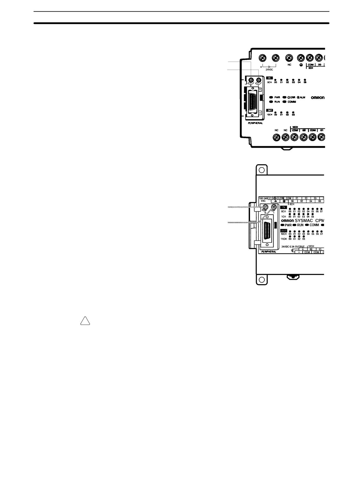
Analog Controls (CPM1/CPM1A/CPM2A Only)
Section 2-13
The storage words are refreshed once with every CPU Unit cycle.
CPM1
The analog setting for control 0 is in SR 250.
The analog setting for control 1 is in SR 251.
CPM1A/CPM2A
The analog setting for control 0 is in SR 250.
The analog setting for control 1 is in SR 251.
Note The above diagram shows the CPM2A, but the settings are the same for the
CPM1A.
!
Caution The analog setting may change with changing temperatures. Do not use the
analog adjustment controls for applications that require a precise, fixed setting.
147
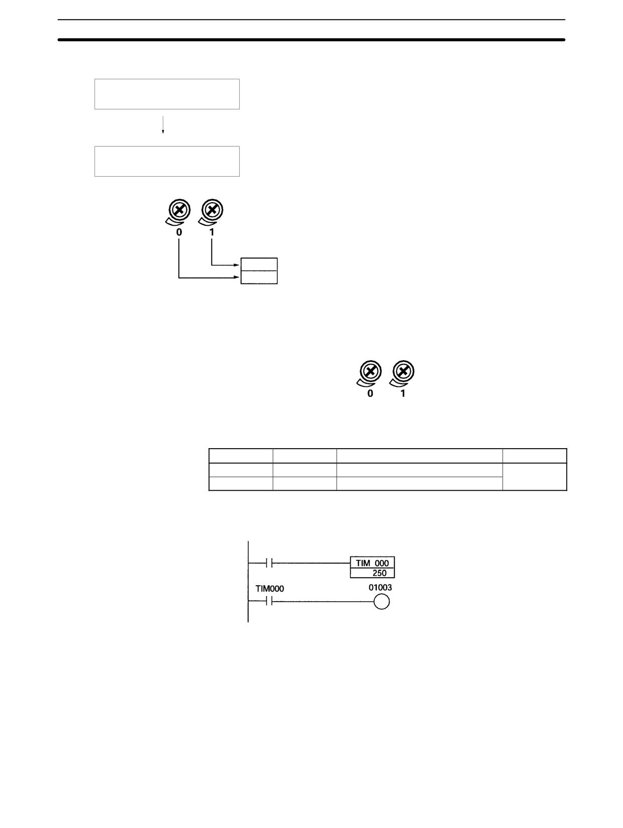
Quick-response Inputs
Section
2-14
Using Analog Controls
Make the analog settings.
Use a Phillips screwdriver to adjust the controls.
Connect a Programming Device such as a Programming Console, and
check the values stored in SR 250 and SR 251.
Create a ladder diagram program.
Read the values in SR 250 and SR 251 with the ladder diagram program.
Analog control 0
Analog control 1
SR 251
Analog control 1 set value (SV)
SR 250
Analog control 0 set value (SV)
Making the Analog
Use a Phillips screwdriver to adjust the analog controls. The set values can be
Settings
checked by connecting a Programming Device such as a Programming Console
and reading the values stored in SR 250 and SR 251.
Analog control 0
Analog control 1
Ladder Diagram
The following table shows the words and bits where the analog settings are
Programming
stored.
Word
Bit
Name
Value
SR 250
00 to 15
Analog control 0 SV storage area
0000 to 0200
(BCD)
SR 251
00 to 15
Analog control 1 SV storage area
In the following example program, the analog control SV (0000 to 0200 BCD)
stored in SR 250 is set as a timer SV. The timer’s set range is 0.0 s to 20.0 s.
Start bit
Specifies SR 250 for the timer SV.
2-14 Quick-response Inputs
2-14-1 CPM1/CPM1A Quick-response Inputs
The CPM1/CPM1A have quick response inputs that can be used to enable in-
putting shorter signals.
All 10-point CPU Units have 2 quick-response input terminals and the 20-, 30-,
and 40-point CPU Units have 4 quick-response input terminals. The same termi-
nals are used for quick-response inputs and interrupt inputs.
148
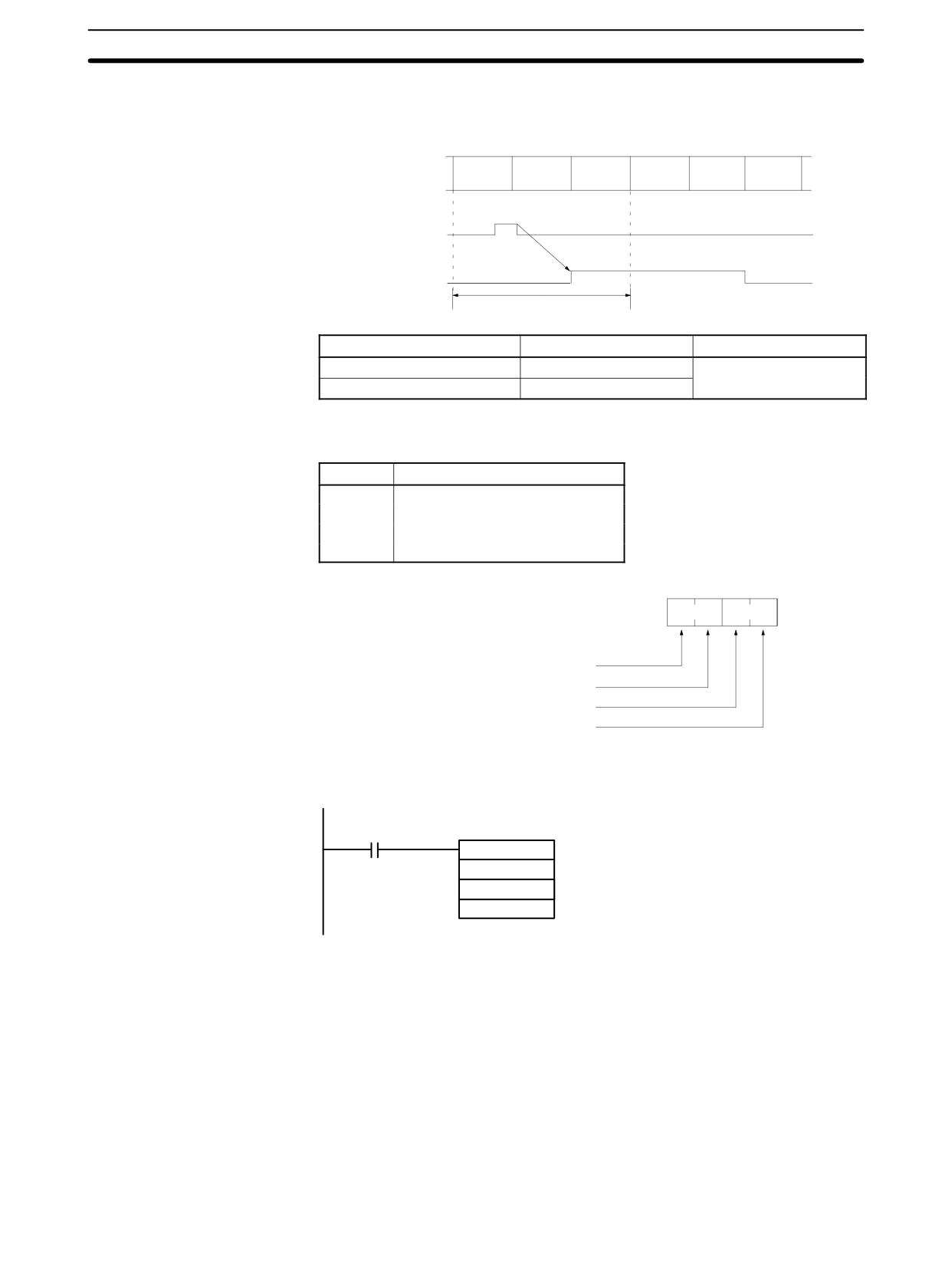
Quick-response Inputs
Section
2-14
Quick-response Operation
Quick-response inputs have an internal buffer, so input signals shorter than one
cycle can be detected. Signals with a pulse width as short as 0.2 ms can be de-
tected, regardless of their timing during the PC cycle.
Overseeing
Program
I/O
Overseeing
Program
I/O
processes
execution
refreshing
processes
execution
refreshing
Input signal
(00003)
IR 00003
One cycle
CPU Unit
Input bits
Min. input pulse width
10-point CPU Units
IR 00003 to IR 00004
0.2 ms
20-, 30-, 40-point CPU Units
IR 00003 to IR 00006
Setting Quick-response
The input bits in the above table can be set as quick-response inputs in
Inputs
DM 6628, as shown in the following table.
Word
Settings
DM 6628
0: Normal input
1: Interrupt input
2: Qu ick-response inpu t
(Default setting: 0)
Bit
15
0
DM 6628
Setting for input 00006: Set to 2
Setting for input 00005: Set to 2
Setting for input 00004: Set to 2
Setting for input 00003: Set to 2
Program Example
In this example, DM 6628 has been set to 0002.
25315 First Cycle Flag
ON for 1 cycle
@INT(89)
000
Mask/unmask input interrupts.
000
#000E
Unmasks 00003 (interrupt input 0), masks others.
149
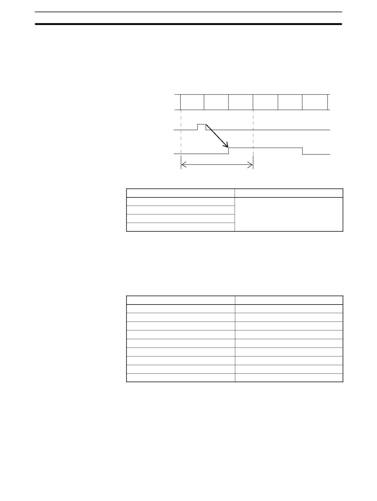
Quick-response Inputs
Section
2-14
2-14-2 CPM2A/CPM2C Quick-response Inputs
The CPM2A and CPM2C have four inputs used for quick-response inputs
(shared with interrupt inputs and 2-kHz high-speed counter inputs). With quick-
response inputs, signals that are changed within a cycle can be received by
maintaining an internal buffer.
Shared
Calculation
I/O refresh
Shared
Calculation
I/O refresh
processing processing
processing processing
Input terminal
(00003)
00003
1 cycle
Input number (See note.)
Minimum input signal width
00003
50 µs
00004
00005
00006 (See note 2.)
Note
1. Input numbers 00003 to 00006 can be used as interrupt inputs, 2-kHz high-
speed counter inputs, or quick-response inputs. If they are not used for any
of these purposes, then they can be used as ordinary inputs.
2. Input number 00006 does not exist in CPM2C CPU Units with 10 I/O points.
The following table shows the relationships between quick-response inputs and
the CPM2A/CPM2C’s other functions.
Function
Interval timer interrupts
Synchronized pulse control
Can be used simultaneously.
Interrupt inputs
See note 1.
Interval timer interrupts
Can be used simultaneously.
High-speed counters
Can be used simultaneously.
Interrupt inputs (counter mode)
See note 2.
Pulse outputs
Can be used simultaneously.
Quick-response inputs
See note 3.
Input time constant
See note 4.
Clock
Can be used simultaneously.
Note
1. Quick-response inputs utilize the interrupt input function, so the same input
number from 00003 to 00006 cannot be assigned for both a quick-response
input and an interrupt input in the PC Setup.
2. A quick-response input and an interrupt in counter mode cannot be as-
signed the same input number in the PC Setup.
3. The input numbers allocated for quick-response inputs are 00003 to 00006.
These inputs can be set and operated as quick-response inputs.
4. Input time constants are disabled for all inputs that are set as quick-re-
sponse inputs.
150
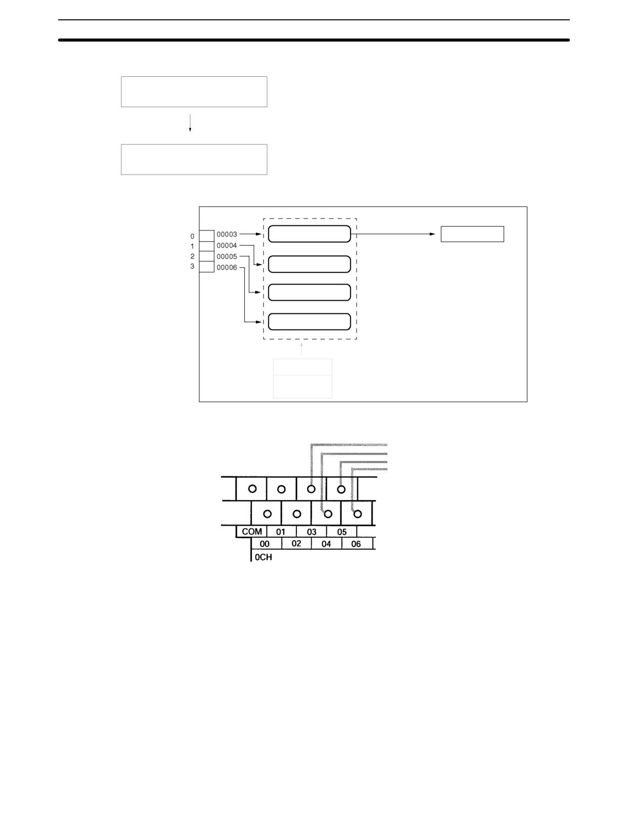
Quick-response Inputs
Section
2-14
Using Quick-response Inputs
Wire the inputs.
Input numbers 00003, 00004, 00005, and 00006
PC Setup (DM 6628)
2: Use as quick-response inputs.
Quick-response input 0
Quick response
Quick-response inputs
Quick-response input 1
Quick-response input 2
Quick-response input 3
PC Setup
DM 6628
Wiring the Inputs
Wire the CPM2A’s inputs as shown in the following diagram.
Input 00003: Quick-response input 0
Input 00004: Quick-response input 1
Input 00005: Quick-response input 2
Input 00006: Quick-response input 3
151
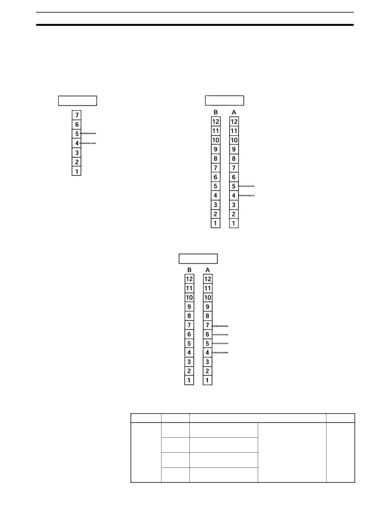
Quick-response Inputs
Section
2-14
Wire the CPM2C’s inputs as shown in the following diagram.
Note The following examples are for Fujitsu-compatible connectors. Input bit ad-
dresses and connector pin numbers depend on the models. Refer to the CPM2C
Operation Manual (W356) or the CPM2C-S Operation Manual (W377) for de-
tails.
CPU Units with 10 I/O Points
Input terminal
Input connector (See above note.)
Input 00004: Quick-response input 1
Input 00003: Quick-response input 0
00004: Quick-response input 1
00003: Quick-response input 0
CPU Units with 20/32 I/O Points
Input connector (See above note.)
00006: Quick-response input 3*
00005: Quick-response input 2*
00004: Quick-response input 1
00003: Quick-response input 0
PC Setup
To use quick-response inputs with the CPM2A or CPM2C, make the following
settings in the System Setup Area (DM 6628) from a Programming Device.
Word
Bits
Function
Setting
DM 6628
00 to 03
Interrupt setting for
0: Ordinary input
2
input number 3
1: Interrupt input
04 to 07
Interrupt setting for
(interrupt input mode or
input number 4
counter mode)
08 to 11
Interrupt setting for
2: Quick-response input
input number 5*
12 to 15
Interrupt setting for
input number 6*
152
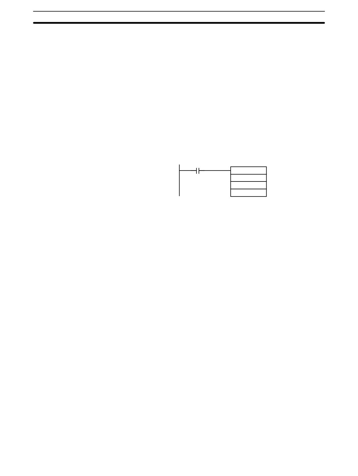
Macro Function
Section
2-15
Note *Input numbers 00005 and 00006 does not exist in CPM2C CPU Units with 10
I/O points.
The settings will go into effect when the mode is changed (from PROGRAM to
MONITOR/RUN) or when the power supply is turned ON to the PC.
2-15
Macro Function
The macro function allows a single subroutine (programming pattern) to be used
by simply changing the I/O word. A number of similar program sections can be
managed with just one subroutine, thereby greatly reducing the number of steps
in the program and making the program easier to understand.
Using Macros
To use a macro, call a subroutine by means of the MACRO instruction,
MCRO(99), as shown below, in stead of SBS(91) (SUBROUTINE ENTRY).
MCRO(99)
Subroutine No
Fist input word
First output word
When MCRO(99) is executed, operation will proceed as follows:
1, 2, 3...
1. The contents of the four consecutive words beginning with the first input
word will be transferred to SR 232 through SR 235.
2. The specified subroutine will be executed until RET(93) (Subroutine Return)
is executed.
3. The contents of SR 236 through SR 239 (results of the subroutine execu-
tion) will be transferred to the four consecutive words beginning with the first
output word.
4. MCRO(99) will then be finished.
When MCRO(99) is executed, the same instruction pattern can be used as
needed simply by changing the first input word or the first output word.
The following restrictions apply when the macro function is used.
• The only words that can be used for each execution of the macro are the four
consecutive words beginning with the first input word number (for input) and
the four consecutive words beginning with the first output word (for output).
• The specified inputs and outputs must correctly correspond to the words used
in the subroutine.
• Even when the direct output method is used for outputs,subroutine results will
be actually reflected in the specified output words only when the subroutine
has been completed (step 3 above).
Note
SR 232 through SR 239 can be used as work bits when MCRO(99) is not used.
The first input word and the first output word can be specified not with I/O bits, but
also with other bits (such as HR bits, work bits, etc.) or with DM words.
Subroutines called by MCRO(99) are defined by SBN(92) and RET(93), just as
are ordinary subroutines.
153
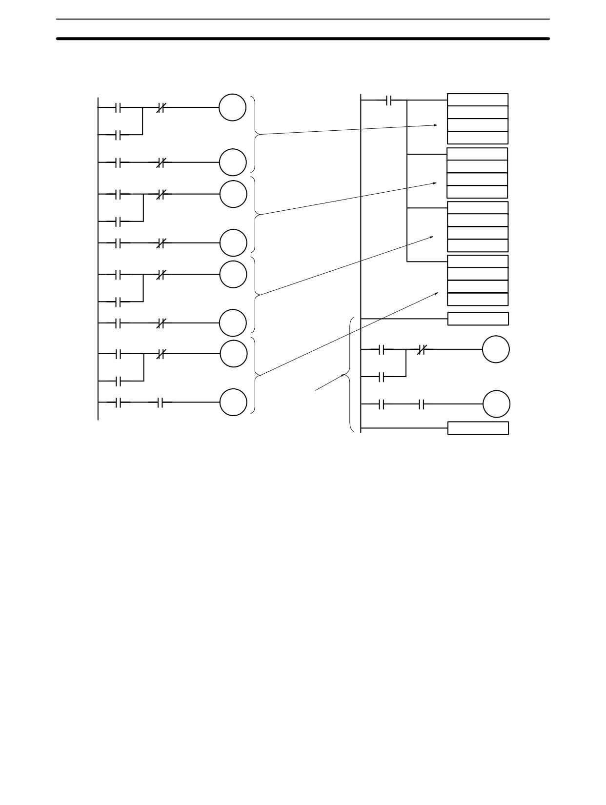
Calculating with Signed Binary Data
Section
2-16
Application Example
When a macro is used, the program can be simplified as shown below.
Macro not used
Macro used
25313 (Always ON)
00000
20001
MCRO(99)
20000
030
20000
000
200
00001
00002
MCRO(99)
20001
030
002
00200
20501
20500
205
MCRO(99)
20500
030
00201
00202
005
20501
210
00500
21001
MCRO(99)
21000
030
010
21000
220
00501
00502
SBN(92)
030
21001
23200
23601
01000
22001
23600
22000
23600
22000
00101
00102
23201
23202
22001
Subroutine used
23201
to define macro
RET(93)
2-16
Calculating with Signed Binary Data
The CPM1/CPM1A/CPM2A/SRM1(-V2) allow calculations on signed binary
data. The following instructions manipulate signed binary data. Signed data is
handled using 2’s complements.
CPM2A/CPM2C and
The following signed-binary instructions are available in CPM2A, CPM2C, and
SRM1(-V2) Instructions
SRM1(-V2) PCs:
• BINARY ADD - ADB(50)
• BINARY SUBTRACT - SBB(51)
• 2’S COMPLEMENT - NEG(--)
CPM1/CPM1A Instructions
The following signed-binary instructions are available in CPM1/CPM1A PCs:
• BINARY ADD - ADB(50)
• BINARY SUBTRACT - SBB(51)
Signed Data Calculations
Addition
Subtraction
7 + 3 = 10
7 - 3 = 4
(-7) + 3 = -4
(-7) - 3 = -10
7 + (-3) = 4
7 - (-3) = 10
(-7) + (-3) = -10
(-7) - (-3) = -4
154
Differential Monitor
Section
2-17
2-16-1 Definition of Signed Binary Data
Signed binary data is manipulated using 2’s complements and bit 15 is used as
the sign bit. The range of data that can be expressed using one word is as fol-
lows:-32,768 to 32,767 (8000 to 7FFF hexadecimal).
The following table shows equivalents between decimal and hexadecimal data.
Decimal
4-digit Hexadecimal
32,767
7FFF
32,766
7FFE
2
0002
1
0001
0
0000
-1
FFFF
-2
FFFE
-32,767
8001
–32,768
8000
2-16-2 Arithmetic Flags
The results of executing signed binary instructions is reflected in the arithmetic
flags. The flags and the conditions under which it will turn ON are given in the
following table. The flags will be OFF when these conditions are not met.
Flag
ON conditions
Carry Flag (SR 25504)
Carry in an addition.
Negative results for subtraction.
Equals Flag (SR 25506)
The results of addition, subtraction,
multiplication, or division is 0.
Results of converting 2’s complement is 0.
2-16-3 Inputting Signed Binary Data Using Decimal Values
Although calculations for signed binary data use hexadecimal expressions, in-
puts from the Programming Console or SSS can be done using decimal inputs
and mnemonics for the instructions. The procedure to using the Programming
Console to input using decimal values is shown in the CPM1 Operation Manual,
CPM1A Operation Manual, CPM2A Operation Manual, CPM2C Operation
Manual, and SRM1 Master Control Unit Operation Manual. Refer to the SSS Op-
eration Manual: C-series PCs for details on using the SSS.
Inputting Instructions
Refer to the CPM1 Operation Manual, CPM1A Operation Manual, CPM2C Op-
eration Manual, CPM2A Operation Manual, and SRM1 Master Control Unit Op-
eration Manual details on inputting instructions from the Programming Console.
2-17
Differential Monitor
The CPM1/CPM1A, CPM2A//CPM2C, and SRM1(-V2) support differential
monitoring from either the Programming Console or the SSS. The operator can
detect on OFF-to-ON or ON-to-OFF transition in a specified bit. When the speci-
fied transition takes place, the transition is indicated on the display and a buzzer
sounds to enable easy recognition of the transition.
Refer to the CPM1 Operation Manual, CPM1A Operation Manual, CPM2A Op-
eration Manual, CPM2C Operation Manual, or SRM1 Master Control Units Op-
eration Manual for details on the Programming Console Differential Monitor pro-
cedure and to the SSS Operation Manual: C-series PCs for the SYSMAC Sup-
port Software procedure.
155
Expansion Instructions (CPM2A/CPM2C/SRM1(-V2) Only)
Section
2-18
2-18
Expansion Instructions (CPM2A/CPM2C/SRM1(-V2) Only)
A set of expansion instructions is available for the CPM2A, CPM2C (including
the CPM2C-S), and SRM1(-V2) to aid in special programming needs. Function
codes can be assigned to up to 18 of the expansion instructions to enable using
them in programs. This allows the user to pick the instructions needed by each
CPM2A, CPM2C, or SRM1(-V2) program to more effectively use the function
codes required to input instructions.
The mnemonics of expansion instructions are followed by “(--)” as the function
code to indicate that they must be assigned function codes by the user in the
instructions table before they can be used in programming (unless they are used
under their default settings).
Any of the instructions not assigned function codes will need to be assigned
function codes in the instructions table used by the Programming Device and the
CPM2A/CPM2C or SRM1(-V2) before they can be used in programming. The
assignments of expansion instructions in the instructions table will change the
meaning of instructions and operands, so be sure to set the instructions table
before programming and transfer the proper instructions table to the CPM2A/
CPM2C or SRM1(-V2) before program execution.
Example: CPM2A/CPM2C PCs
The specific instructions used in the following example are for the CPM2A/
CPM2C. The concepts are the same for the SRM1(-V2).
INI
INI
Function code 61
Function code 61
SPED
SPED
Function code 64
PULS
Function code 64
PULS
MAX
MAX
Function code 65
MIN
Function code 65
MIN
SUM
SUM
At the time of shipping, the function codes are
If pulse outputs are not being used, and if
assigned as shown above. (In this example,
maximum values, minimum values, and
the instructions all relate to pulse outputs.)
sums are required, then the Set Instructions
operation can be used as shown above to
reassign instructions in the instruction table.
Note
1. Set the PC model to “CQM1” when setting the expansion instructions for the
SRM1(-V2) or CPM2A/CPM2C from the SSS.
2. The PC Setup must be set for user-defined expansion instruction function
codes in order for function codes to be assigned. Set bits 08 to 11 of
DM 6602 to 1.
156
Expansion Instructions (CPM2A/CPM2C/SRM1(-V2) Only)
Section
2-18
2-18-1 CPM2A/CPM2C/CPM2C-S Expansion Instructions
The following 18 function codes can be used for expansion instructions: 17, 18,
19, 47, 48, 60, 61, 62, 63, 64, 65, 66, 67, 68, 69, 87, 88, and 89. The function
code assignments can be changed with a Programming Console or the Support
Software.
Refer to 4-4-5 Assigning Expansion Instruction Function Codes in the CPM2A or
CPM2C Operation Manual for the Programming Console procedure.
Refer to the SSS Operation Manual: C-series PCs for the SSS procedure.
Refer to the SYSMAC-CPT Support Software Quick Start Guide (W332) and
User Manual (W333) for the SYSMAC-CPT Support Software procedure.
The expansion instructions that can be used are listed below, along with the de-
fault function codes that are assigned when the PC is shipped.
Mnemonic
Function code
ASFT
17
---
18
---
19
RXD
47
TXD
48
CMPL
60
INI
61
PRV
62
CTBL
63
SPED
64
PULS
65
SCL
66
BCNT
67
BCMP
68
STIM
69
---
87
---
88
INT
89
ACC
---
AVG
---
FCS
---
HEX
---
HMS
---
MAX
---
MIN
---
NEG
---
PID
---
PWM
---
SCL2
---
SCL3
---
SEC
---
SRCH
---
STUP
---
SUM
---
SYNC
---
TIML
---
TMHH
---
ZCP
---
ZCPL
---
157
Expansion Instructions (CPM2A/CPM2C/SRM1(-V2) Only)
Section
2-18
2-18-2 SRM1(-V2) Expansion Instructions
The following 18 function codes can be used for expansion instructions: 17, 18,
19, 47, 48, 60, 61, 62, 63, 64, 65, 66, 67, 68, 69, 87, 88, and 89. The function
code assignments can be changed with a Programming Console or the Support
Software.
Refer to 4-2-6 Setting Expansion Instructions in the SRM1 Master Control Unit
Operation Manual for the Programming Console procedure. Refer to the SSS
Operation Manual: C-series PCs for the SSS procedure. Refer to the SYSMAC-
CPT Support Software Quick Start Guide (W332) and User Manual (W333) for
the SYSMAC-CPT Support Software procedure.
The expansion instructions that can be used are listed below, along with the de-
fault function codes that are assigned when the SRM1(-V2) is shipped.
Mnemonic
Function code
ASFT
17
---
18
---
19
RXD
47
TXD
48
CMPL
60
---
61
---
62
---
63
---
64
---
65
SCL*
66
BCNT
67
BCMP
68
STIM
69
---
87
---
88
---
89
FCS
---
HEX
---
NEG*
---
PID*
---
STUP
---
ZCP*
---
Note *SCL(66), NEG(--), PID(--), and ZCP
(--) are supported by the
SRM1-C0j-V2 CPUs only.
158
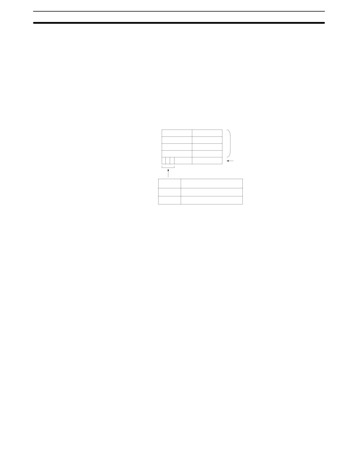
Using the CPM2A/CPM2C Clock Function
Section
2-19
2-19
Using the CPM2A/CPM2C Clock Function
The CPM2A PCs and some CPM2C (including the CPM2C-S) PCs have a built-
in clock function. This section explains how to use the clock.
2-19-1 Data Area Words
This following illustration shows the configuration of the words (AR 17 through
AR 21) that are used with the clock. These words can be read and used as re-
quired. (AR 17 is provided so that the hour and minute can be accessed quickly.)
15
8
7
0
AR 17
Hour
Minute
2 digits BCD each.
AR 18
Minute
Second
(Only the last 2 digits of the
AR 19
Date
Hour
year are given.)
AR 20
Year
Month
AR 21
Day of week
00 to 06: Sunday to Saturday
AR 2115
Clock Set Bit
AR 2114
Clock Stop Bit
AR 2113
30-Second Adjustment Bit
2-19-2 Setting the Time
To set the time, use a programming device as follows:
Setting Everything
1, 2, 3...
1. Turn ON AR 2114 (Clock Stop Bit) to stop the clock and allow AR 18 through
AR 21 to be overwritten.
2. Using a Programming Device, set AR 18 through AR 20 (minute/second,
date/hour, and year/month) and AR 2100 through AR 2107 (day of week).
3. Turn ON AR 2115 (Clock Set Bit) when the time set in step 2 is reached. The
clock will start operating from the time that is set, and the Clock Stop Bit and
Clock Set BIt will be turned OFF automatically.
Setting Only the Seconds
It is also possible, by using AR 2113, to simply set the seconds to “00” without
going through a complicated procedure. When AR 2113 is turned ON, the clock
time will change as follows:
If the seconds setting is from 00 to 29, the seconds will be reset to “00” and the
minute setting will remain the same.
If the seconds setting is from 30 to 59, the seconds will be reset to “00” and the
minute setting will advance by one.
When the time setting is complete, AR 2113 will turn OFF automatically.
Note The time can be set easily using menu operations from a Programming Console
or SSS. Refer to the CPM2A Operation Manual or the CPM2C Operation Manu-
al for the Programming Console procedure or to the SSS Operation Manual: C-
series PCs for the SSS procedure.
159
SECTION 3
Using Expansion Units
This section describes how to use the CPM1A-MAD01, CPM1A-MAD11, and CPM2C-MAD11 Analog I/O Units; the
CPM1A-TS001/002/101/102 and CPM2C-TS001/101 Temperature Sensor Units; the CPM1A-SRT21 and CPM2C-SRT21
CompoBus/S I/O Link Units; and the CPM1A-DRT21 DeviceNet I/O Link Unit. The CPM1A-MAD11 and CPM2C-MAD11
Analog I/O Units provide the same functions, and are thus described in the same section even though they are supported by
different PCs.
3-1
Analog I/O Units
162
3-1-1
CPM1A-MAD01 Analog I/O Unit
162
3-1-2
CPM1A-MAD11 and CPM2C-MAD11 Analog I/O Units
173
3-2
Temperature Sensor Units
189
3-2-1
CPM1A/CPM2A Temperature Sensor Units
189
3-2-2
CPM2C Temperature Sensor Units
190
3-2-3
Using Temperature Sensor Units
191
3-2-4
Connecting Temperature Sensor Units
191
3-2-5
Setting Temperature Ranges
193
3-2-6
Connecting Temperature Sensors
196
3-2-7
Ladder Programming
198
3-2-8
Two-decimal-place Mode
204
3-3
CompoBus/S I/O Link Units
210
3-4
DeviceNet I/O Link Unit
215
161
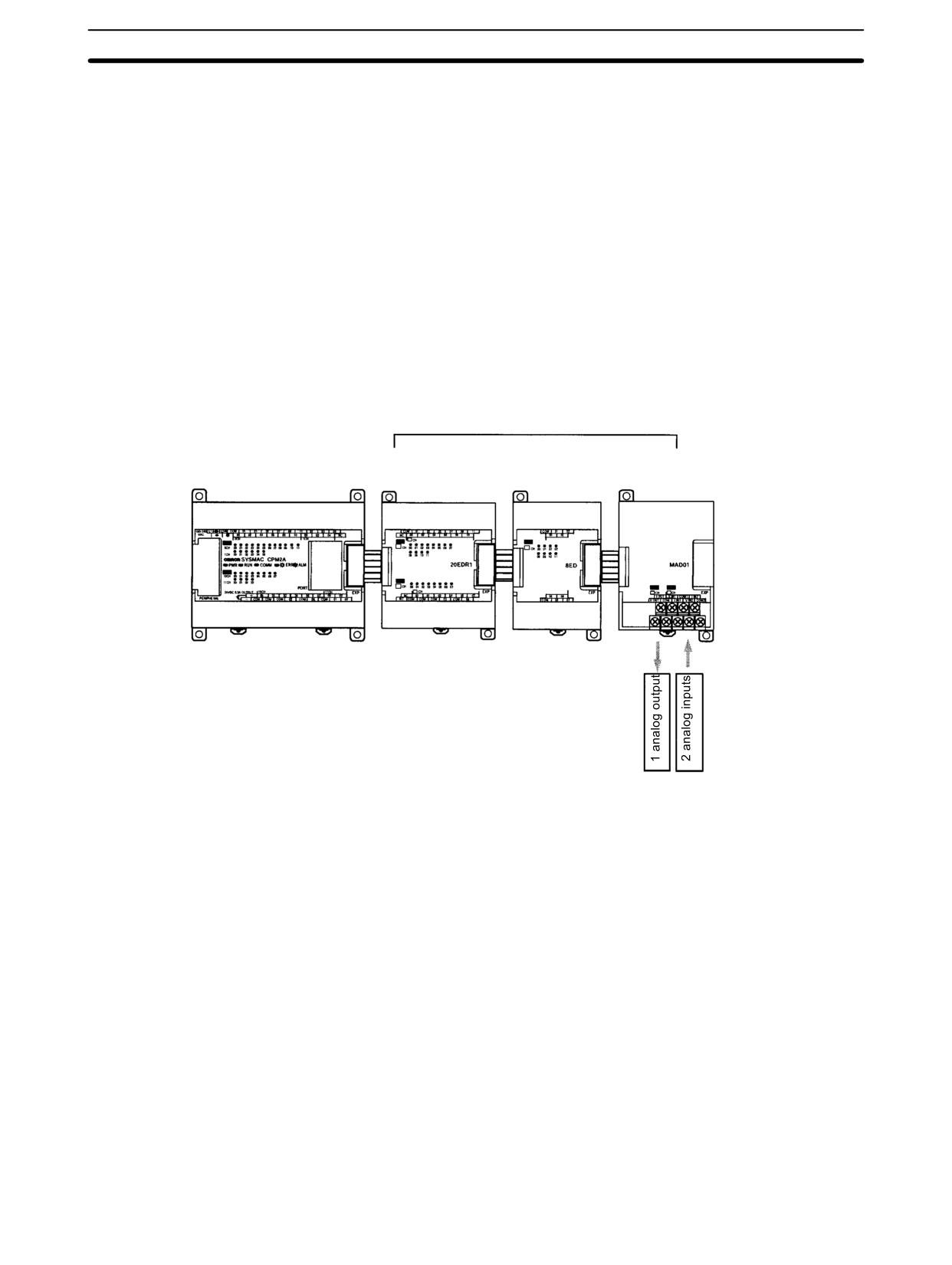
Analog I/O Units
Section
3-1
3-1
Analog I/O Units
3-1-1
CPM1A-MAD01 Analog I/O Unit
A maximum of 3 Expansion Units or Expansion I/O Units, including CPM1A-
MAD01 Analog I/O Units, can be connected to a CPM1, CPM1A (see note) or
CPM2A PC. One Analog I/O Unit allows 2 analog inputs and 1 analog output.
With the maximum of 3 Analog I/O Units connected, 6 analog inputs and 3 ana-
log outputs are possible.
• The analog input range can be set to 0 to 10 VDC, 1 to 5 VDC, or 4 to 20 mA
with a resolution of 1/256.
• An open-circuit detection function can be used with the 1 to 5 VDC and 4 to
20 mA settings.
• The analog output range can be set to 0 to 10 VDC, 4 to 20 mA, or -10 to
10 VDC. The output has a resolution of 1/256 when the range is set to 0 to
10 VDC or 4 to 20 mA, or a resolution of 1/512 when set to -10 to 10 VDC.
A maximum of 3 Expansion Units or Expansion I/O Units can be connected.
CPM1(-V1)/CPM1A/CPM2A
CPM1A-20EDR1
CPM1A-8ED
CPM1A-MAD01
CPU Unit
Expansion I/O Unit
Expansion I/O Unit Analog I/O Unit
Note The CPM1-30CDR-j-V1 is the only CPM1 CPU Unit to which 3 Expansion
Units or Expansion I/O Units can be connected. Only one Expansion Unit or
Expansion I/O Unit can be connected to models without the “V1” suffix. Analog
Units cannot be connected to 10-point or 20-point CPM1A CPU Units. You must
use a 30-point or 40-point CPU Unit to connect to the CPM1A.
162
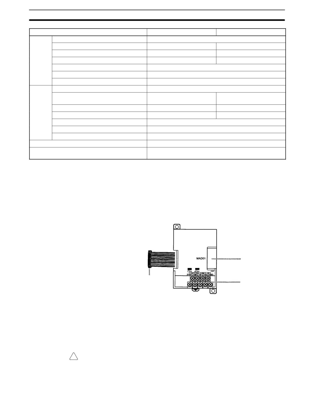
Analog I/O Units
Section
3-1
Item
Voltage I/O
Current I/O
Analog
Number of inputs
2
Input
Input signal range
0 to 10 V/1 to 5 V
4 to 20 mA
Section
Max. rated input
±15 V
±30 mA
External input impedance
1 MΩ min.
250 Ω rated current
Resolution
1/256
Accuracy
1.0% full scale
A/D conversion data
8-bit binary
Analog
Number of outputs
1
Output
Output signal range
0 to 10 V or
4 to 20 mA
Section
-10 to 10 V
(See
Max. external output current
5 mA
---
note 1.)
Allowable external output load resistance
---
350 Ω
Resolution
1/256 (1/512 when the output signal range is -10 to 10 V)
Accuracy
1.0% of full scale
Set data
8-bit signed binary
Conversion time
10 ms max. per Unit (See note 2.)
Isolation method
Photocoupler isolation between I/O terminals and PC signals.
No isolation between analog I/O signals.
Note
1. With analog outputs it is possible to use both voltage outputs and current
outputs at the same time. In this case however, the total output current must
not exceed 21 mA.
2. The conversion time is the total time for 2 analog inputs and 1 analog output.
Part Names
Expansion connector
Expansion I/O connecting cable
Analog I/O terminals
Analog I/O Terminals
Connected to analog I/O devices.
Expansion I/O
Connected to the CPU Unit or previous Expansion Unit. The cable is provided
Connecting Cable
with the Unit and cannot be removed.
!
Caution Do not touch the cables during operation. Static electricity may cause operating
errors.
Expansion Connector
Connected to the next Expansion Unit or Expansion I/O Unit.
163
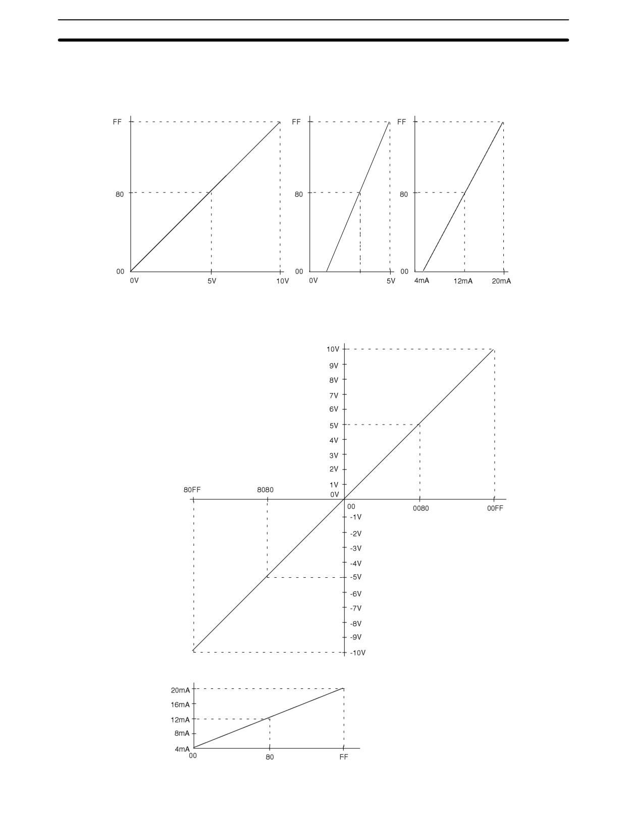
Analog I/O Units
Section
3-1
Analog I/O Signal Ranges
Analog Input Signal Ranges
0 to 10 V inputs
1 to 5 V inputs
4 to 20 mA inputs
Conversion value
Conversion value
Conversion value
1 V
3 V
Input signal
Input signal
Input signal
Analog Output Signal Ranges
0 to 10 V outputs and
-10 to +10 V outputs
Set value
Set value
4 to 20 mA outputs
Set value
164
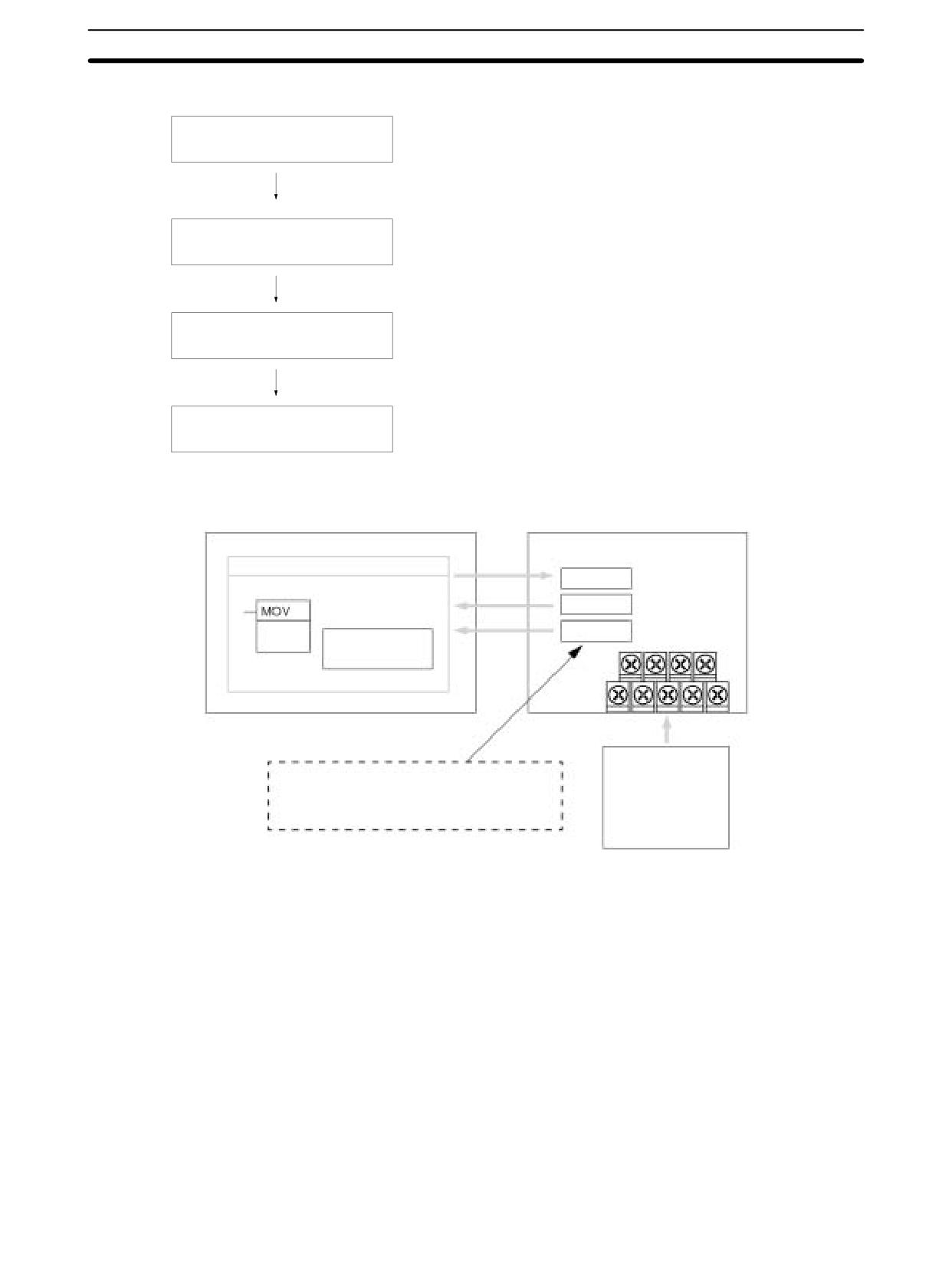
Analog I/O Units
Section
3-1
Using Analog I/O
Analog inputs:
0 to 10 V, 1 to 5 V, or 4 to 20 mA
Set the I/O range
Analog outputs:
0 to 10 V, -10 to +10 V, or 4 to 20 mA
Connect the Unit
Connect the Analog I/O Unit.
Wire the analog I/O
Connect an analog input device.
Write the range code.
Create a ladder program
Analog input:
Read converted data.
Analog output:
Write set value.
Analog Inputs
CPU Unit
Analog I/O Unit
Ladder program
Word (n + 1)
Range code
Word (m + 1)
Analog input 1
(21)
MOVE instruction
conversion value
Word (m + 2)
Analog input 2
Writes the range code.
conversion value
Reads the conversion
value.
Analog devices
Temperature sensor
Where “m” is the last input word and “n” is the
Pressure sensor
last output word allocated to the CPU Unit, or
Speed sensor
previous Expansion Unit or Expansion I/O Unit.
Flow sensor
Voltage/current meter
165
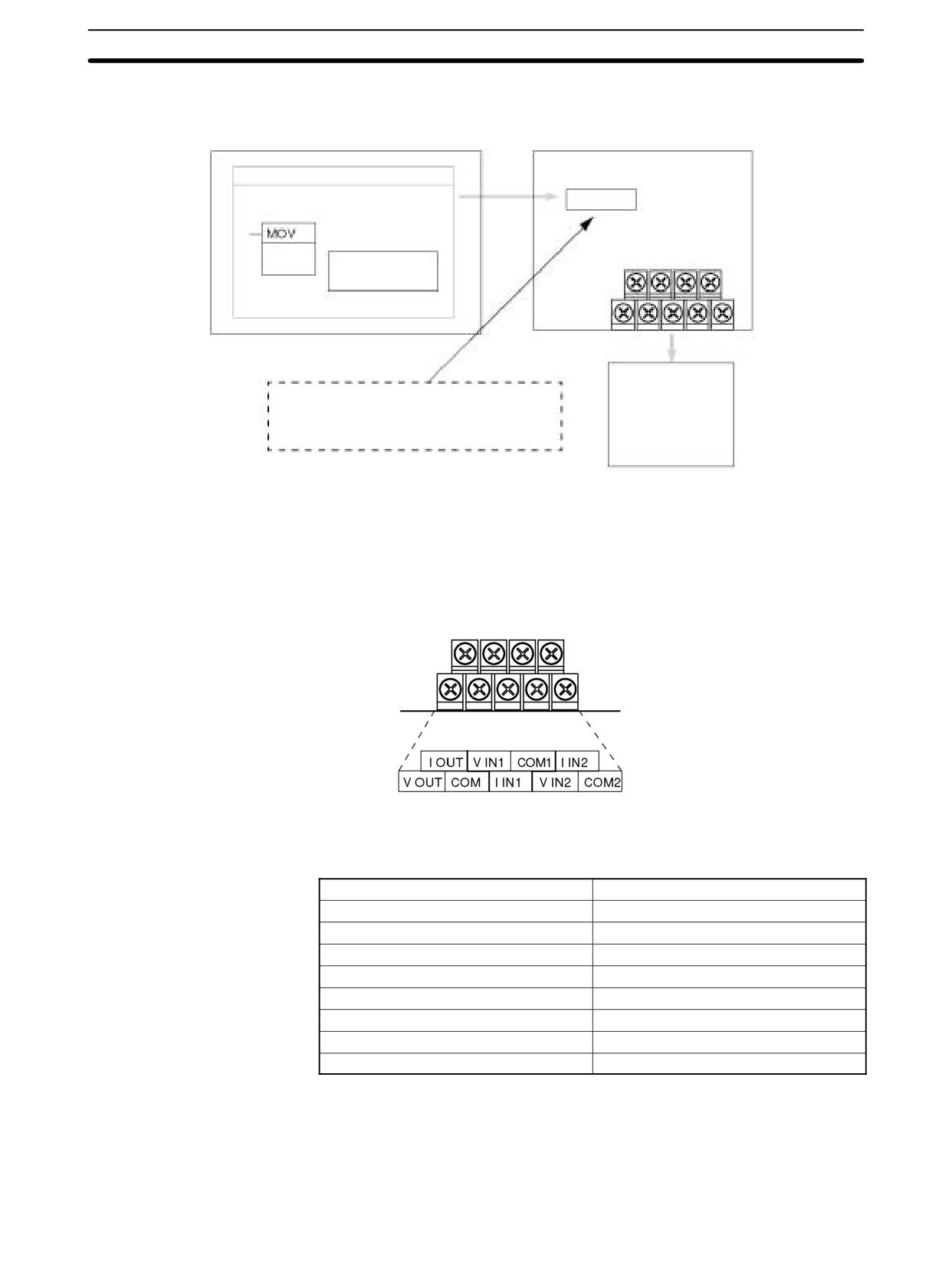
Analog I/O Units
Section
3-1
Analog Outputs
CPU Unit
Analog I/O Unit
Ladder program
(See note.)
Word (n + 1)
Range code
Analog output set value
(21) MOVE instruction
Writes the range code
Writes the set value
Analog devices
Adjustment equipment
Where “n” is the last output word allocated to
Servo Controller
the CPU Unit, or previous Expansion Unit or
Variable speed device
Expansion I/O Unit.
Recorder
Other
Note Word (n + 1) can be used for either the range code or the analog output set value.
The I/O signal range is set by wiring the I/O terminal and by writing the range
Setting I/O Signal Range
code to the Analog I/O Unit’s output word.
I/O Terminal Arrangement
Note When using current inputs, short terminal V IN1 with I IN1
and terminal V IN2 with I IN2.
V OUT
Voltage output
I OUT
Current output
COM
Output common
V IN1
Voltage input 1
I IN1
Current input 1
COM1
Input common 1
V IN2
Voltage input 2
I IN2
Current input 2
COM2
Input common 2
Range Code
The range code must be set for the Analog I/O Unit to convert data.
The 8 range code settings provide 8 combinations of signal ranges for the ana-
log inputs and analog output, as shown in the following table.
166
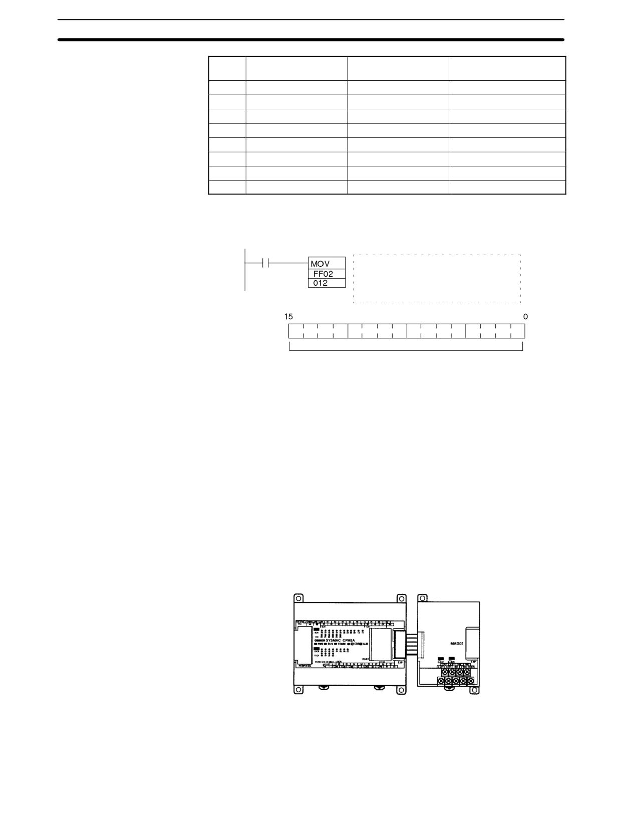
Analog I/O Units
Section
3-1
Range
Analog input 1
Analog input 2
Analog output
code
signal range
signal range
signal range
FF00
0 to 10 V
0 to 10 V
0 to 10 V or 4 to 20 mA
FF01
0 to 10 V
0 to 10 V
-10 to 10 V or 4 to 20 mA
FF02
1 to 5 V or 4 to 20 mA
0 to 10 V
0 to 10 V or 4 to 20 mA
FF03
1 to 5 V or 4 to 20 mA
0 to 10 V
-10 to 10 V or 4 to 20 mA
FF04
0 to 10 V
1 to 5 V or 4 to 20 mA
0 to 10 V or 4 to 20 mA
FF05
0 to 10 V
1 to 5 V or 4 to 20 mA
-10 to 10 V or 4 to 20 mA
FF06
1 to 5 V or 4 to 20 mA
1 to 5 V or 4 to 20 mA
0 to 10 V or 4 to 20 mA
FF07
1 to 5 V or 4 to 20 mA
1 to 5 V or 4 to 20 mA
-10 to 10 V or 4 to 20 mA
Write the range code to the Analog I/O Unit’s output word (n + 1) in the first cycle
of program execution.
SR 25315 First Cycle Flag
ON for 1 cycle
(21)
Analog input 1:
1 to 5 V/4 to 20 mA
Analog input 2:
0 to 10 V
Analog output:
0 to 10 V/4 to 20 mA
(n + 1)
Range code (4-digit hexadecimal)
The Analog I/O Unit will not start converting analog I/O values until the range
code has been written.
Once the range code has been set, it is not possible to change the setting while
power is being supplied to the CPU Unit. To change the I/O range, turn the CPU
Unit OFF then ON again.
Note If a range code other than those specified in the above table is written to n+1, the
range code will not be received by the Analog I/O Unit and analog I/O conversion
will not start.
This section describes how to connect an Analog I/O Unit to the CPU Unit.
Analog I/O Unit
Connection
A maximum of 3 Expansion Units or Expansion I/O Units, including Analog I/O
Units, can be connected to one PC. When the Analog I/O Unit is used in com-
bination with other Expansion Units or Expansion I/O Units, there are no restric-
tions on the connection order.
CPM1/CPM1A/CPM2A
Analog I/O Unit
CPU Unit
I/O Allocation
I/O is allocated for the Analog I/O Unit in the same way as other Expansion Units
or Expansion I/O Units starting from the next word following the last allocated
word on the CPU Unit, or previous Expansion Unit or Expansion I/O Unit. When
“m” is the last allocated input word and “n” the last allocated output word on the
167
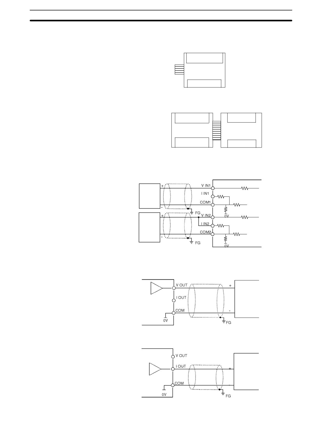
Analog I/O Units
Section
3-1
CPU Unit, or previous Expansion Unit or Expansion I/O Unit, the allocation will
be as follows:
Analog I/O Unit
(m + 1)
(m + 2)
2 analog inputs
1 analog output
(n + 1)
For example, in the following diagram an Analog I/O Unit is connected to a CPU
Unit with 30 I/O points.
IR 000
IR 002
Input address
IR 001
IR 003
30-point CPU
Analog I/O
Unit
Unit
IR 010
Output address
IR 012
IR 011
Wiring Analog I/O Devices
Analog Input Wiring
2-core shielded
Analog I/O Unit
twisted-pair cable
Analog
output
250 Ω
device
voltage
output
10 kΩ
Analog
output
250 Ω
device
current
output
10 kΩ
Analog Output Wiring
Voltage Outputs
2-core shielded
Analog I/O Unit
twisted-pair cable
Analog
input
device
voltage
input
Current Outputs
Analog I/O Unit
2-core shielded
twisted-pair cable
Analog
output
device
current
input
168