Inspection Plus software for Haas machining centres. Programming manual (H-2000-6222-0A-B) - page 2
Variable inputs
4-1
Chapter 4
Variable inputs
This chapter lists the variable outputs that may be produced by some of the macros. You
will be referred to this chapter from other chapters when a variable output is produced.
Contained in this chapter
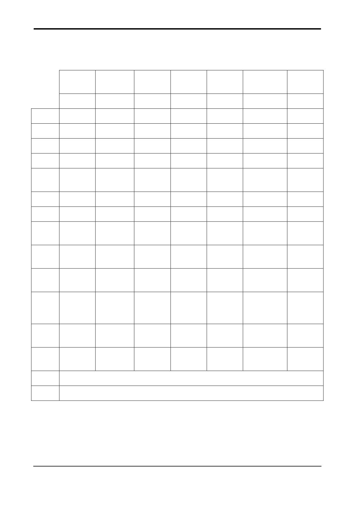
Variable outputs - chart 1
4-2
Variable outputs - chart 2
4-3
Publication No. H-2000-6222
4-2
Variable inputs
Variable outputs - chart 1
Single
Web/
Bore/boss
Internal
External
4th axis
XY angle
surface
pocket
corner
corner
measure
G65P9811
G65P9812
G65P9814
G65P9815
G65P9816
G65P9817/18
G65P9843
#185
X position
X position
X position
X position
X position
#186
Y position
Y position
Y position
Y position
Y position
#187
Z position
#188
Size
Size
Size
#189
X surface
X surface
4th angle
Angle
angle
angle
#190
X error
X error
X error
X error
X error
#191
Y error
Y error
Y error
Y error
Y error
#192
Z error
Y surface
Y surface
angle
angle
#193
Size error
Size error
Size error
Y angle
Y angle
Height error
Height
error
error
error
#194
X angle
X angle
Angle error
Angle
error
error
error
#195
True
True
True
True
True
position
position
position
position
position
error
error
error
error
error
#196
Metal
Metal
Metal
condition
condition
condition
#197
Direction
indicator
#198
Out of tolerance flag (1 to 7)
#199
Probe error flag (0 to 2)
Publication No. H-2000-6222
Variable inputs
4-3
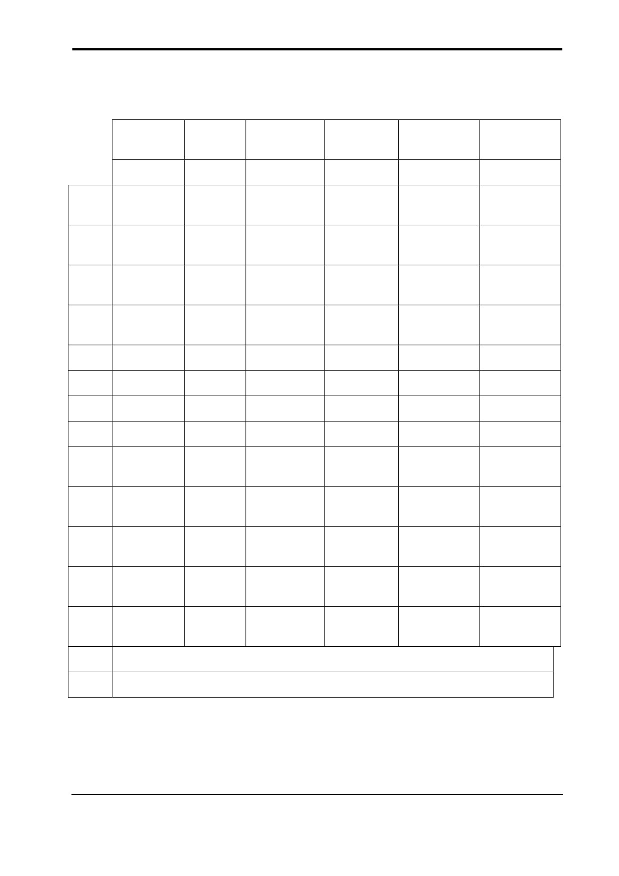
Variable outputs - chart 2
PCD
Stock
Angle single
Angle
3-point
Feature to
bore/boss
allowance
surface
web/pocket
bore/boss
feature
G65P9819
G65P9820
G65P9821
G65P9822
G65P9823
G65P9834
#185
X position
X position
X position
X position
X incremental
from start
distance
#186
Y position
Y position
Y position
Y position
Y incremental
from start
distance
#187
PCD
Z incremental
position
#188
Size
Size from start
Size
Size
Minimum
distance
#189
Angle
Angle
#190
X error
X error
X error
X error
X error
#191
Y error
Y error
Y error
Y error
Y error
#192
PCD error
Z error
#193
Size error
Size error
Size error
Size error
Minimum
distance error
#194
Angle error
Maximum
Angle error
value
#195
True position
Minimum
True position
True position
True position
True position
error
value
error
error
error
error
#196
Metal
Variation
Metal
Metal
Metal
Metal
condition
(stock)
condition
condition
condition
condition
#197
Hole number
Direction
indicator
#198
Out of tolerance flag (1 to 7)
#199
Probe error flag (0 to 2)
Publication No. H-2000-6222
4-4
Variable inputs
This page intentionally left blank.
Publication No. H-2000-6222
Protected positioning cycles
5-1
Chapter 5
Protected positioning cycles
When the probe moves around the workpiece, it is important that the stylus is protected
against a collision with the workpiece. This chapter describes how to use macro O9810 to
set up the protected positioning of the probe. After it is correctly set, the probe will stop
moving in the event of a collision.
Contained in this chapter
Protected positioning (probe trigger monitor) - macro O9810
5-2
Publication No. H-2000-6222
5-2
Protected positioning cycles
Protected positioning (probe trigger monitor) - macro O9810
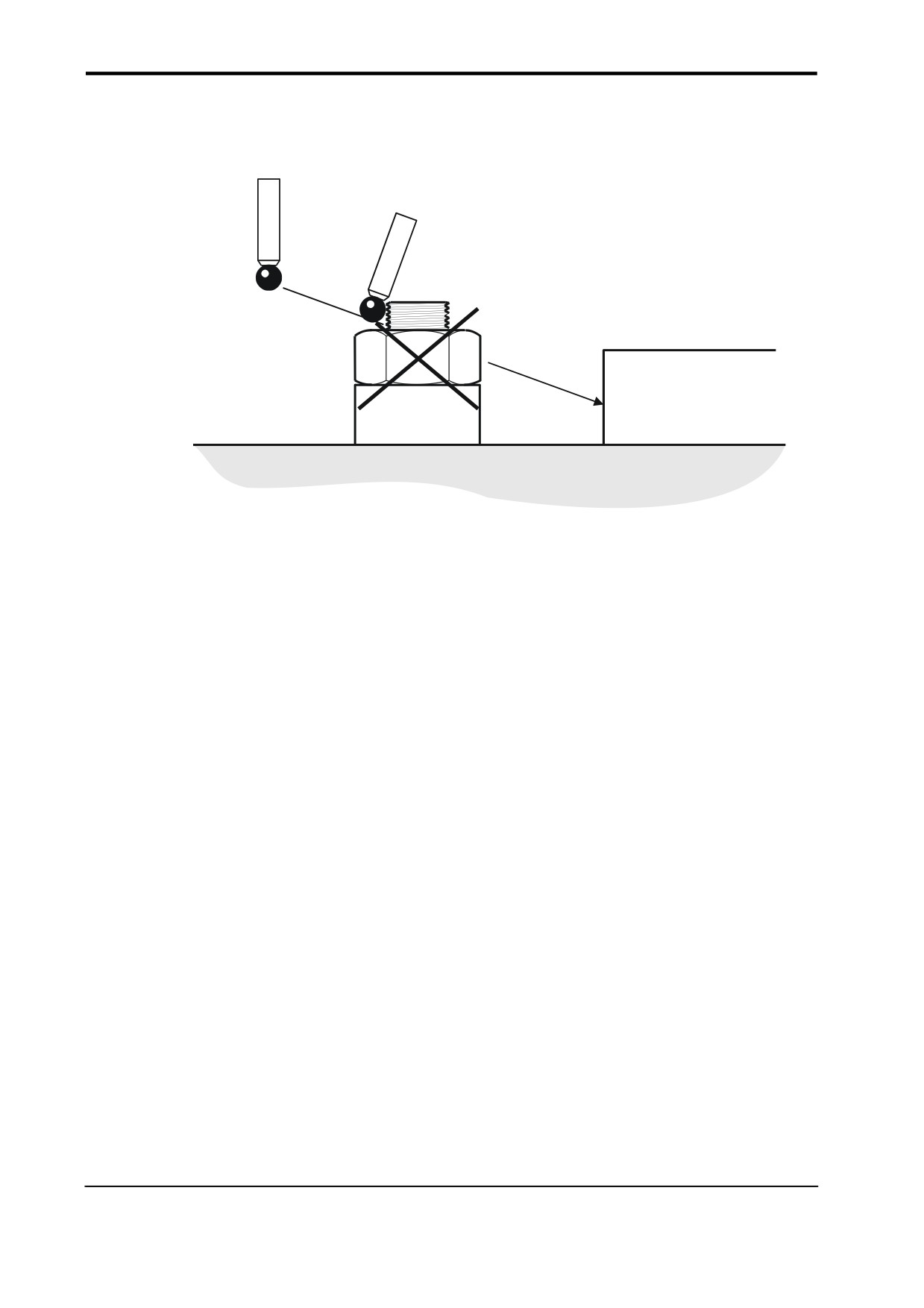
Figure 5.1 Probe protected positioning
Description
It is important when moving around the workpiece to protect the probe stylus against
collision. When this cycle is used, the machine will stop in the event of a collision.
Application
Select the probe and move to a safe plane. The probe should be made active at this point
and then it can be moved to a measuring position using this macro call. In the event of a
collision, the machine will stop and a macro alarm PATH OBSTRUCTED will result, or an
error flag #198 will be set (see Mm input).
Format
G65 P9810 Xx Yy Zz [Ff Mm]
where [ ] denote optional inputs
Example: G65 P9810 Z10. F0.8 M0.2
Publication No. H-2000-6222
Protected positioning cycles
5-3
Inputs
Xx,Yy,Zz x,y,z = These are the target positions for the probe positioning move.
Ff
f =
The modal feedrate for all protected positioning moves. The
feedrate will be modal to this macro and subsequent feedrate calls
are unnecessary unless a change of feedrate is required. The
maximum safe fast feedrate established during installation should
not be exceeded.
Mm
m = 1.0 Will set a probe trigger flag (no PATH OBSTRUCTED alarm)
#198 = 0 (no probe trigger)
#198 = 7 (probe triggered)
Example
G1G54X20.Y50.
G43H20Z100.
Move to a safe plane.
G65P9832
Spin the probe on (includes M19) or M19 for spindle orientation.
G65P9810Z10.F3000 Protected positioning move.
G65P9811Z0S1
Single surface measure.
Publication No. H-2000-6222
5-4
Protected positioning cycles
This page intentionally left blank.
Publication No. H-2000-6222
Calibration cycles
6-1
Chapter 6
Calibration cycles
Before a probe is used, it is important that you calibrate it correctly. This chapter describes
the four macros that you should use for calibrating a probe. If you need to know more
about calibrating a probe, you will find helpful information contained in Chapter 1, “Getting
started”.
Contained in this chapter
Calibration cycles - an overview
6-2
Calibrating the probe's length - macro O9801
6-3
Calibrating the stylus X and Y offsets - macro O9802
6-5
Calibrating the stylus ball radius - macro O9803
6-8
Calibrating the vector stylus ball radius - macro O9804
6-11
Example 1 - Full calibration in an internal feature
6-14
Example 2 - Full calibration on an external feature
6-16
Publication No. H-2000-6222
6-2
Calibration cycles
Calibration cycles - an overview
Four calibration cycles are provided with the Inspection Plus software. These may be
used in conjunction with one another for complete calibration of the probe. The purpose of
each macro is summarised below.
Macro O9801 This is used to establish the probe's length in its tool shank.
Macro O9802 This is used to establish the stylus off-centre values.
Macro O9803 This is used to establish the stylus ball radius values. It is suitable for all
measuring cycles except for O9821, O9822 and O9823.
Macro O9804 This is used to establish the vector stylus ball radius values. It is suitable
for all measuring cycles, including O9821, O9822 and O9823.
For complete calibration of a probe system, you must use macros O9801 and O9802, and
either O9803 or O9804. Examples of full calibration procedures are described in the
sections titled “Example 1 - Full calibration in an internal feature” and “Example 2 - Full
calibration on an external feature” at the end of this chapter.
The Renishaw calibration cycles are split into separate cycles for flexibility. If, however,
the calibration feature is accurately known for both size and position, e.g. a ring gauge
where the size is known, and the position is accurately found using a dial test indicator, it
is then possible for you to write a program which completes the full calibration procedure
in one operation by calling all of the above macros.
Publication No. H-2000-6222
Calibration cycles
6-3
Calibrating the probe's length - macro O9801
Tt Tool offset
Zz Ref. height
Z
Y
X
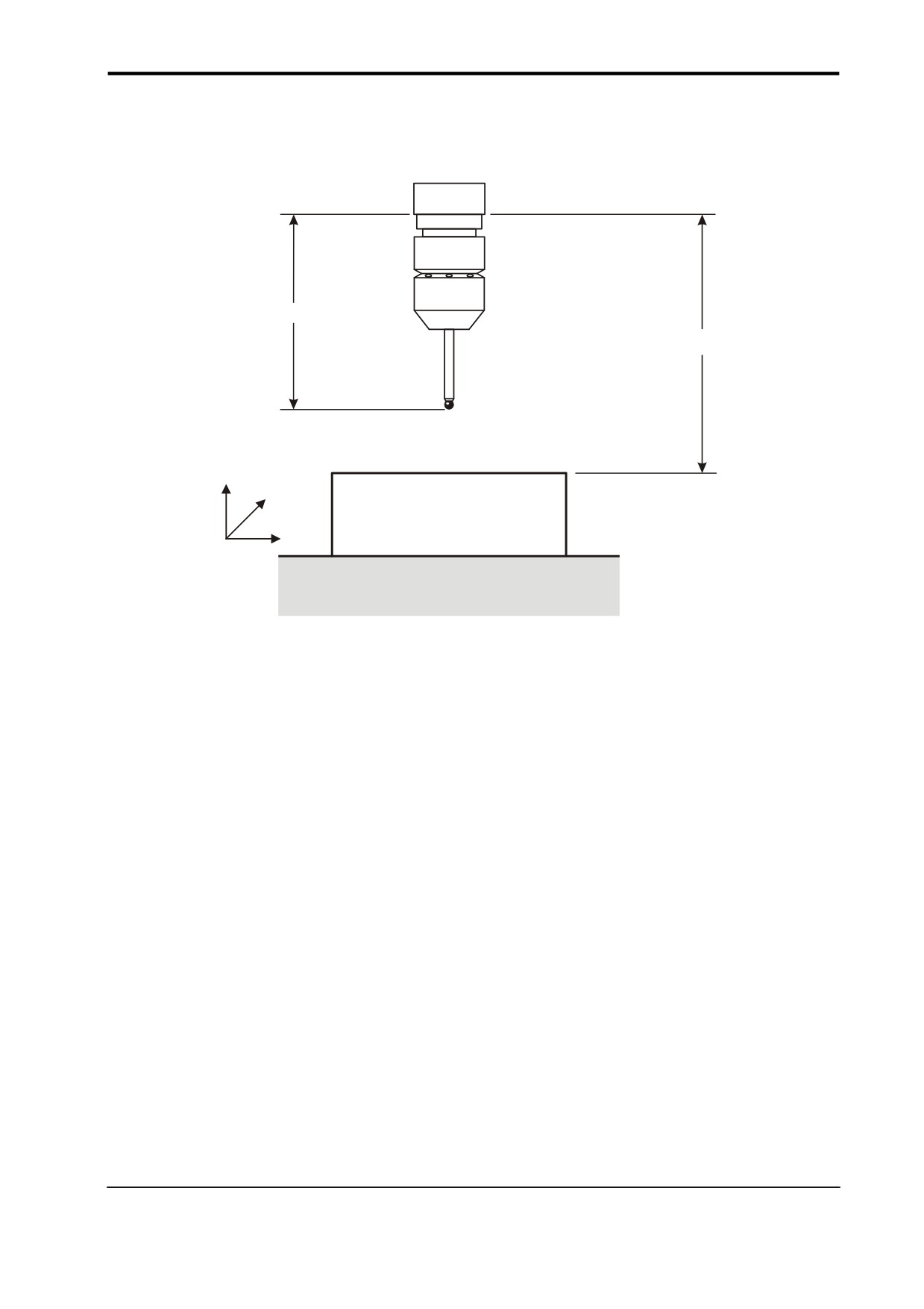
Figure 6.1 Calibrating the probe's length
Description
The probe is positioned adjacent to a Z axis reference surface for calibration. When the
cycle is completed, the active probe tool offset is adjusted to the reference surface.
Application
Load an approximate tool offset. The probe should be positioned adjacent to the reference
surface. When the cycle is run, the surface is measured and the tool offset is reset to a
new value. The probe is returned to the start position.
Format
G65 P9801 Zz Tt
Example: G65 P9801 Z50. T20
Publication No. H-2000-6222
6-4
Calibration cycles
Compulsory inputs
Zz
z = Reference surface position
Tt
t =
The active tool offset number.
Outputs
The active tool offset will be set.
Example
Set X, Y, Z values in work offset G54
O 0001
G90G80G40G0
Preparatory codes for the machine.
G54X0Y0
Start position.
G43H1Z100.
Activate offset 1, go to 100 mm (3.94 in).
G65P9832
Spin the probe on (includes M19) or M19 for spindle orientation.
G65P9810Z10.F3000 Protected positioning move.
G65P9801Z0T1
Datum Z direction.
G65P9810Z100.
Protected positioning move.
G65P9833
Spin the probe off (when applicable).
G28Z100.
Reference return.
H00
Cancel offset.
M30
End of program
NOTE: The tool offset must be active. The active tool offset H word number must be the
same as the T input number (see above)
Publication No. H-2000-6222
Calibration cycles
6-5
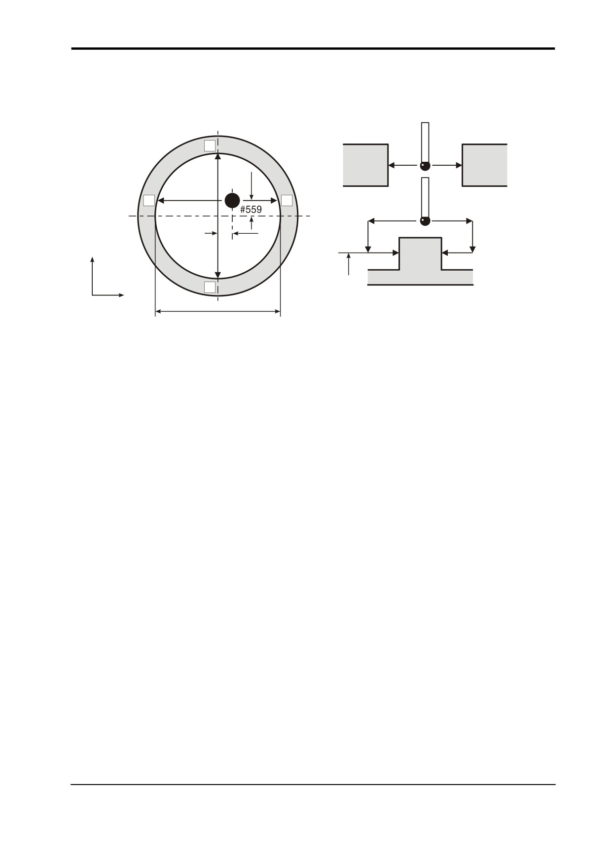
Calibrating the stylus X and Y offsets - macro O9802
4
1
2
#558
Y
Zz
3
X
Dd
Figure 6.2 Calibrating the stylus X and Y offsets
Description
The probe is positioned inside a pre-machined hole at a suitable height for calibration.
When this cycle is completed, the stylus offset amounts in the X and Y axes are stored.
Application
Pre-machine a hole with a suitable boring bar, so that the exact centre of the hole is
known. Position the probe to be calibrated inside the hole, and the spindle on the known
centre position with the spindle orientation active. When the cycle is run, four measuring
moves are made in order to determine the X offset and Y offset of the stylus. The probe is
then returned to the start position.
Format
G65 P9802 Dd [Zz]
where [ ] denote optional inputs
Example: G65 P9802 D50.005 Z50.
Compulsory inputs
Dd
d = Nominal size of feature
Publication No. H-2000-6222
6-6
Calibration cycles
Optional input
Zz
z = The absolute Z axis measuring position when calibrating on an external
feature. If this is omitted, a bore cycle is assumed.
Outputs
The following data will be stored as shown:
#558 (556 + 2) = X axis stylus offset
#559 (556 + 3) = Y axis stylus offset
Example
Stylus X, Y offset calibration
A tool offset must be active before running this program
Position the stylus in the bored hole at the required depth. The spindle centre must be
positioned exactly on the bored hole centre line.
O0002
G90G80G40G0
Preparatory codes for the machine.
G65P9832
Spin the probe on (includes M19), or M19 for spindle orientation.
G65P9802D50.
Calibrate in a 50 mm (1.97 in) diameter bored hole.
G65P9833
Spin the probe off (when applicable).
M30
End of program.
Alternatively
Run a complete positioning and calibration program as follows.
Set the exact X,Y, Z feature positions in a work offset (example using G54).
O0002
G90G80G40G0
Preparatory codes for the machine.
G54X0Y0
Move to centre of the feature.
G43H1Z100.
Activate offset 1, go to 100 mm (3.94 in) above.
G65P9832
Spin the probe on (includes M19), or M19 for spindle orientation.
G65P9810Z-5.F3000
Protected positioning move into hole.
Publication No. H-2000-6222
Calibration cycles
6-7
G65P9802D50.
Calibrate in a 50 mm (1.97 in) diameter bored hole.
G65P9810Z100.F3000 Protected positioning move retract to 100 mm (3.94 in).
G65P9833
Spin the probe off (when applicable).
G28Z100.
Reference return.
H00
Cancel offset (when applicable).
M30
End of program
Publication No. H-2000-6222
6-8
Calibration cycles
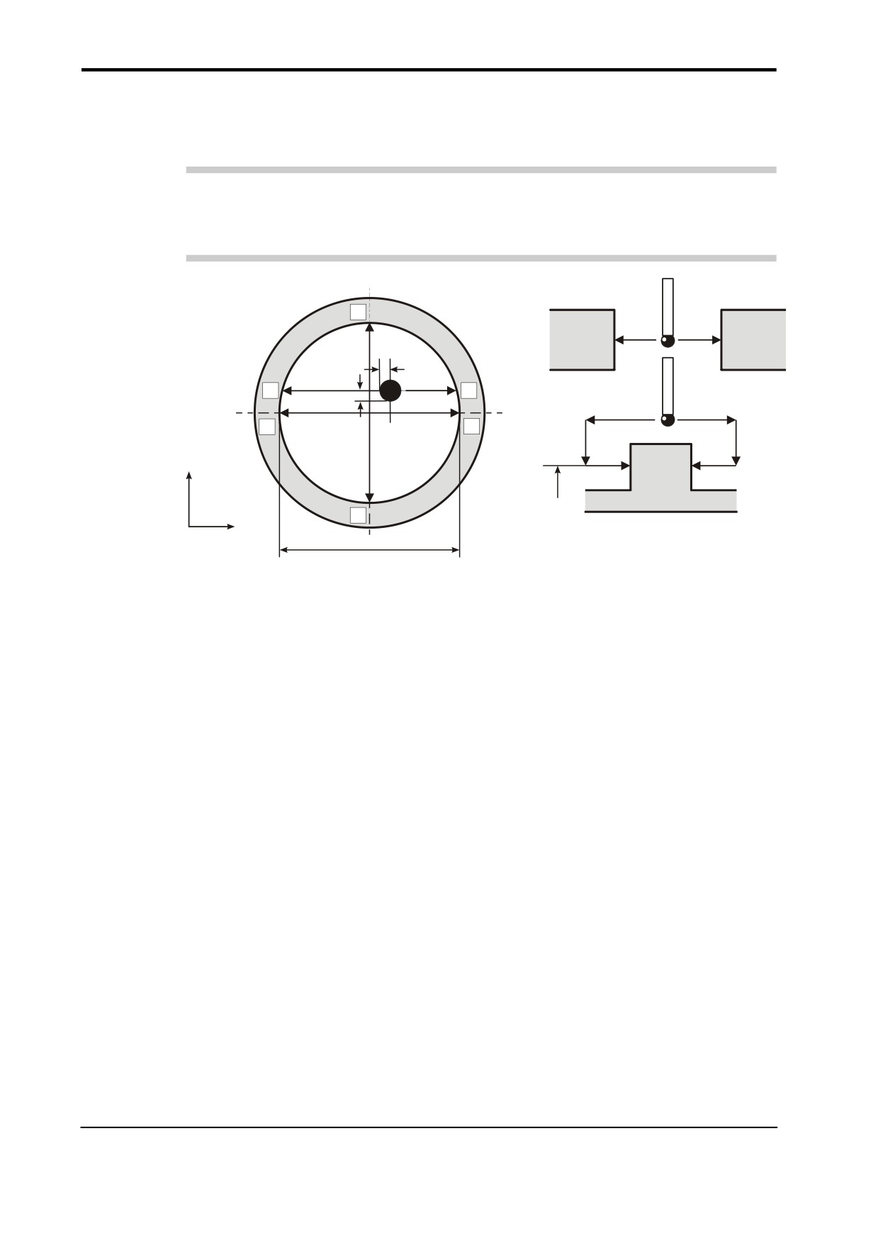
Calibrating the stylus ball radius - macro O9803
NOTE: Do not use this cycle to calibrate the radius of the stylus ball if, subsequently, you
intend using vector measuring macros O9821, O9822 or O9823. The stylus ball radius
must be calibrated using macro O9804 instead.
4
#556
1
2
#557
5
6
Y
Zz
3
X
Dd
Figure 6.3 Calibrating the stylus ball radius
Description
The probe is positioned inside a calibrated ring gauge at a suitable height for calibration.
When this cycle is completed, the stylus ball radius values are stored.
Application
Clamp a calibrated ring gauge on the machine table at an approximately known position.
Position the probe to be calibrated inside the ring gauge on the approximate centre
position, with spindle orientation active. When the cycle is run, six moves are made in
order to determine the stylus ball radius values. The probe is then returned to the start
position.
Format
G65 P9803 Dd [Zz Ss]
where [ ] denote optional inputs
Example: G65 P9803 D50.005 Z50. S1.
Publication No. H-2000-6222
Calibration cycles
6-9
Compulsory inputs
Dd
d = Reference gauge size
Optional inputs
Zz
z = The absolute Z axis measuring position when calibrating on an external
feature. If this is omitted, a ring gauge cycle is assumed.
Ss
s = The work offset number which will be set.
The work offset number will be updated.
S1 to S6 (G54 to G59)
S0 (external work offset).
S110 to S129 (G110 to G129) additional offsets option.
S154.01 to S154.99 (G154 P1 to G154 P99) additional offsets option.
New work offset = active work offset + error.
New external offset = external offset + error.
Outputs
The following data will be stored as shown:
#556 (556 + 0) = X+, X-, stylus ball radius (XRAD)
#557 (556 + 1) = Y+, Y-, stylus ball radius (YRAD)
Example
Stylus ball radius calibration
A tool offset must be active before running this program. If your machine does not retain
the offset then use the alternative example.
Position the probe's stylus approximately on-centre in the ring gauge and at the required
depth.
O0003
G90G80G40G0
Preparatory codes for the machine.
G65P9832
Spin the probe on (includes M19) or M19 for spindle orientation.
G65P9803D50.001
Calibrate in a 50.001 mm (1.9685 in) diameter ring gauge.
G65P9833
Spin the probe off (when applicable).
M30
End of program.
Publication No. H-2000-6222
6-10
Calibration cycles
Alternatively
Run a complete positioning and calibration program as follows.
Set the approximate X, Y, Z feature positions in a work offset (example using G54).
O0003
G90G80G40G00
Preparatory codes for the machine.
G54X0Y0
Move to centre of feature.
G43H1Z100.
Activate offset 1, go to 100 mm (3.94 in) above.
G65P9832
Spin the probe on (includes M19), or M19 for spindle orientation.
G65P9810Z-5.F3000
Protected positioning move into hole.
G65P9803D50.001
Calibrate in a 50.001 mm (1.9685 in) ring gauge.
G65P9810Z100.F3000 Protected positioning move retract to 100 mm (3.94 in).
G65P9833
Spin the probe off (when applicable).
G28Z100.
Reference return.
H00
Cancel offset (when applicable).
M30
End of program.
Publication No. H-2000-6222
Calibration cycles
6-11
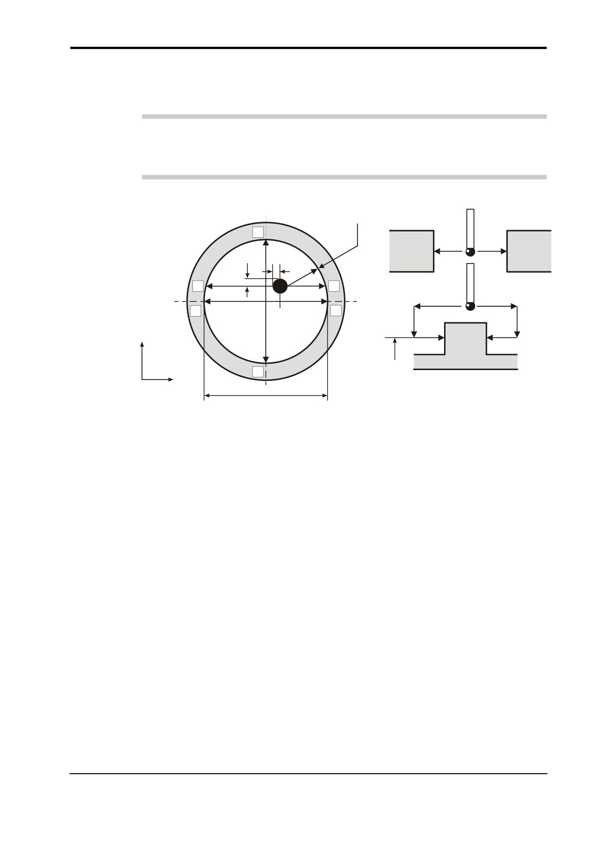
Calibrating the vector stylus ball radius - macro O9804
NOTE: You must use this cycle to calibrate the radius of the stylus ball if you intend using
vector measuring macros O9821, O9822 or O9823 (described in Chapter 8, “Vector
measuring cycles”). Do not calibrate the stylus ball radius using macro O9803.
Additional vector moves (7 to 14)
at every 30°
4
#557
#556
1
2
5
6
Y
Zz
3
X
Dd
Figure 6.4 Calibrating the vector stylus ball radius
Description
The probe is positioned inside a calibrated ring gauge at a suitable height for calibration.
When the cycle is completed, the stylus ball radius values are stored. A total of twelve
calibration radii at 30 degree intervals are established.
Application
Clamp a calibrated ring gauge on the machine table at an approximately known position.
The probe to be calibrated is positioned inside the ring gauge on the approximate centre
position, with spindle orientation active. When the cycle is run, fourteen moves are made
in order to determine the stylus ball radius values. The probe is then returned to the start
position.
Format
G65 P9804 Dd [Zz Ss]
where [ ] denote optional inputs
Example: G65 P9804 D50.005 Z50. S1.
Publication No. H-2000-6222
6-12
Calibration cycles
Compulsory inputs
Dd
d = Reference gauge size.
Optional inputs
Zz
z = The absolute Z axis measuring position when calibrating on an external
feature. If this is omitted, a ring gauge cycle is assumed.
Ss
s = The work offset number which will be set.
The work offset number will be updated.
S1 to S6 (G54 to G59)
S0 (external work offset).
S110 to S129 (G110 to G129) additional offsets option.
S154.01 to S154.99 (G154 P1 to G154 P99) additional offsets option.
New work offset = active work offset + error.
New external offset = external offset + error.
Outputs
The following data will be stored as shown (as O9803):
#556 (556 + 0) = X+, X-, stylus ball radius (XRAD)
#557 (556 + 1) = Y+, Y-, stylus ball radius (YRAD)
Additional vector calibration data:
#566 (556 + 10) = 30 degree stylus ball radius
(VRAD)
#567 (556 + 11) = 60 degree stylus ball radius
(VRAD)
#568 (556 + 12) = 120 degree stylus ball radius
(VRAD)
#569 (556 + 13) = 150 degree stylus ball radius
(VRAD)
#570 (556 + 14) = 210 degree stylus ball radius
(VRAD)
#571 (556 + 15) = 240 degree stylus ball radius
(VRAD)
#572 (556 + 16) = 300 degree stylus ball radius
(VRAD)
#573 (556 + 17) = 330 degree stylus ball radius
(VRAD)
Example
Vector stylus ball radius calibration
A tool offset must be active before running this program. If your machine does not retain
the offset, then use the alternative example.
Position the probe approximately on-centre in the ring gauge and at the required depth.
O0004
G90G80G40G0
Preparatory codes for the machine.
Publication No. H-2000-6222
Calibration cycles
6-13
G65P9832
Spin the probe on (includes M19), or M19 for spindle orientation.
G65P9804D50.001
Calibrate in a 50.001 mm (1.9685 in) diameter ring gauge.
G65P9833
Spin the probe off (when applicable).
M30
End of program.
Alternatively
Run a complete positioning and calibration program as follows.
Set the approximate X, Y, Z feature positions in a work offset (example using G54).
O0004
G90G80G40G0
Preparatory codes for the machine.
G54X0Y0
Move to centre of feature.
G43H1Z100.
Activate offset 1, go to 100 mm (3.94 in) above.
G65P9832
Spin the probe on (includes M19), or M19 for spindle orientation.
G65P9810Z-5.F3000
Protected positioning move into the hole.
G65P9804D50.001
Calibrate in a 50.001 mm (1.9685 in) diameter ring gauge.
G65P9810Z100.F3000 Protected positioning move retract to 100 mm (3.94 in).
G65P9833
Spin the probe off (when applicable).
G28Z100.
Reference return.
H00
Cancel offset (when applicable).
M30
End of program.
Publication No. H-2000-6222
6-14
Calibration cycles
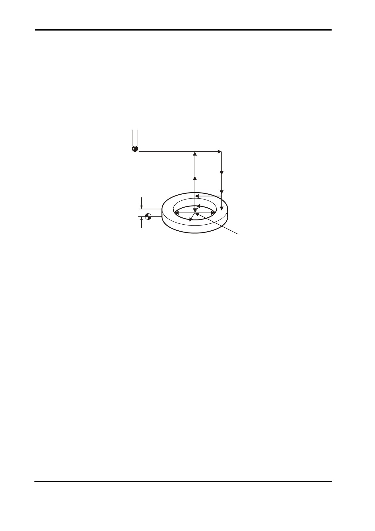
Example 1 - Full calibration in an internal feature
This example describes how to carry out full calibration of the probe in an internal feature
using macros O9801, O9802 and O9804, using a 50.001 mm (1.9685 in) diameter ring
gauge, with a known centre position and top face height value.
The approximate probe length must be stored in the tool offset register before running this
program. Set the exact X, Y, and Z feature positions in a work offset (example using G54).
1
2
12
3
11
4
10
6
7
5
8 and 9
Figure 6.5 Full calibration in an internal feature
O0006
G90G80G40G0
Preparatory codes for the machine.
1.
G54X35.Y0
Move off centre of feature for height setting.
2.
G43H1Z100.
Activate offset 1, go to 100 mm (3.94 in) above.
3.
G65P9832
Spin the probe on (includes M19), or M19 for spindle
orientation.
4.
G65P9810Z30.F3000
Protected positioning move above reference surface.
5.
G65P9801Z20.006T1.
Calibrate the probe length. Surface at 20.006 mm
(0.7876 in)
6.
G65P9810X0Y0
Protected positioning move to centre.
7.
G65P9810Z5.
Protected positioning move into hole.
8.
G65P9802D50.
Calibrate in a 50 mm (1.97 in) diameter bored hole to
establish the X,Y stylus offset.
Publication No. H-2000-6222
Calibration cycles
6-15
9.
G65P9804D50.001
Calibrate in a 50.001 mm (1.9685 in) diameter ring
gauge to establish the ball radius values, including the
vector directions.
10.
G65P9810Z100.F3000
Protected positioning move retract to 100 mm
(3.94 in).
11.
G65P9833
Spin the probe off (when applicable).
12.
G28Z100.
Reference return.
H00
Cancel offset (when applicable)
M30
End of program
Publication No. H-2000-6222
6-16
Calibration cycles
Example 2 - Full calibration on an external feature
This example describes how to carry out full calibration of the probe on an external feature
using macros O9801, O9802 and O9804, using a 50.001 mm (1.9685 in) diameter pin
gauge, with a known centre position and a Z reference surface.
The approximate probe length must be stored in the tool offset register before running this
program. Set the exact X, Y pin feature positions and Z surface height in a work offset
(example using G54).
1
2
11
3
10
4
9
7 and 8
6
5
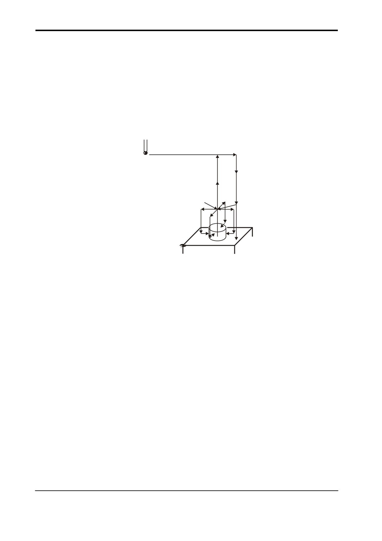
Figure 6.6 Full calibration on an external feature
O0006
G90G80G40G0
Preparatory codes for the machine.
1.
G54X135.Y100.
Move to centre of feature for height setting.
2.
G43H1Z100.
Activate offset 1, go to 100 mm (3.94 in) above.
3.
G65P9832
Spin the probe on (includes M19), or M19 for spindle
orientation.
4.
G65P9810Z30.F3000
Protected positioning move above reference surface.
5.
G65P9801Z0.T1.
Calibrate the probe length. Z surface at zero.
6.
G65P9810X100.Y100.
Protected positioning move to centre.
7.
G65P9802D50.001Z10.
Calibrate on a 50.001 mm (1.9685 in) diameter pin
gauge to establish the X,Y stylus offset.
8.
G65P9804D50.001Z10.
Calibrate on a 50.001 mm (1.9685 in) diameter pin
gauge to establish the ball radius values, including the
vector directions.
Publication No. H-2000-6222
Calibration cycles
6-17
9.
G65P9810Z100.F3000
Protected positioning move retract to 100 mm
(3.94 in).
10.
G65P9833
Spin the probe off (when applicable).
11.
G28Z100.
Reference return.
H00
Cancel offset (when applicable)
M30
End of program
Publication No. H-2000-6222
6-18
Calibration cycles
This page intentionally left blank.
Publication No. H-2000-6222
Measuring cycles
7-1
Chapter 7
Measuring cycles
This chapter describes how to use the non-vector measuring cycle macros. The probe
stylus ball radius must be calibrated using either macro O9803 or O9804 (see Chapter 6,
“Calibration cycles”) before using the macros described here.
Contained in this chapter
X Y Z single surface measurement - macro O9811
7-2
Web / pocket measurement - macro O9812
7-5
Bore / boss measurement - macro O9814
7-9
Finding an internal corner - macro O9815
7-13
Finding an external corner - macro O9816
7-17
Publication No. H-2000-6222
7-2
Measuring cycles
X Y Z single surface measurement - macro O9811
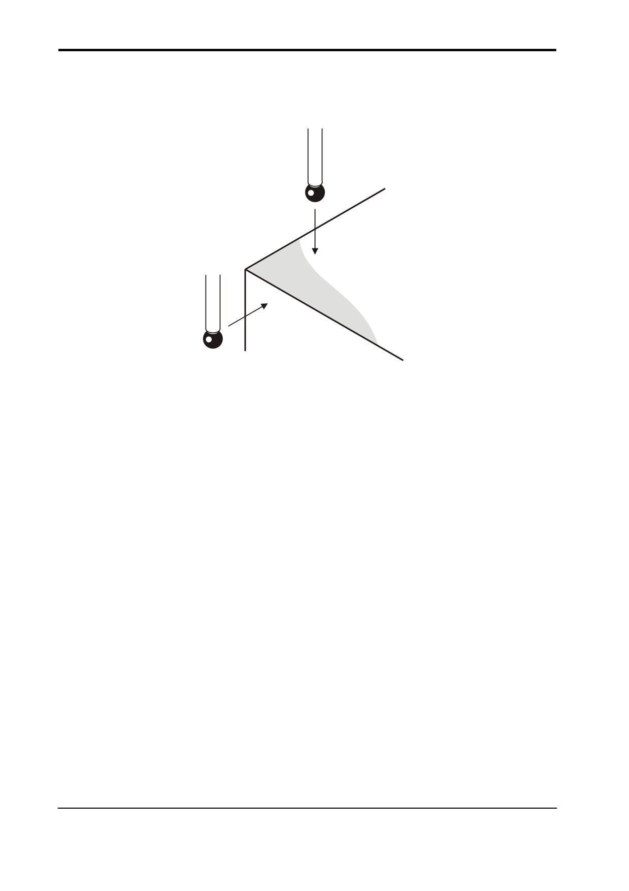
Z
X,Y
Figure 7.1 Measurement of a single surface
Description
This cycle measures a surface to establish the size or position.
Application
The probe should be positioned with its tool offset active adjacent to the surface. The
cycle measures the surface and returns to the start position.
There are two possibilities as follows:
1.
The surface can be treated as a size, where the tool offset is updated in conjunction
with the Tt and the Hh input.
2.
The surface can be treated as a reference surface position, for the purpose of
adjusting a work offset using the Ss and Mm inputs.
Format
G65 P9811 Xx or Yy or Zz [Ee Ff Hh Mm Qq Ss Tt Uu Vv Ww]
where [ ] denote optional inputs
Example:
G65 P9811 X50. E0.005 F0.8 H0.2 M.2 Q10. S1. T20. U.5V.5W2.
Publication No. H-2000-6222
Measuring cycles
7-3
Compulsory inputs
Xx or Yy or Zz
x,y,z = The surface position or size.
Optional inputs
Hh
h = The tolerance value of a feature dimension being measured.
Mm m = The true position tolerance of a feature. A cylindrical zone about the
theoretical position.
Qq
q = The probe's overtravel distance for use when the default values are
unsuitable. The probe will then travel beyond the expected position when
it searches for a surface. Default values are 4 mm (0.16 in) in the Z axis
and 10 mm (0.394 in) in the X,Y axis.
Ss
s = The work offset number which will be set.
The work offset number will be updated.
S1 to S6 (G54 to G59)
S0 (external work offset).
S110 to S129 (G110 to G129) additional offsets option.
S154.01 to S154.99 (G154 P1 to G154 P99) additional offsets option.
New work offset = active work offset + error.
New external offset = external offset + error.
Tt
t =
This is the tool offset number to be updated .
Ww w = Print data
1.
= Increment the feature number only.
2.
= Increment the component number, and reset the feature number.
For optional inputs Ee, Ff, Uu, and Vv see Chapter 3, “Optional inputs”.
Publication No. H-2000-6222
7-4
Measuring cycles
Example
X and Z single surface measurement
1.
T01M06
Select the probe.
1
2
2.
G54X-40.Y20.
Start position.
3
12
3.
G43H1Z100.
Activate offset 1, go to 100 mm (3.94 in).
4
11
4.
G65P9832
Spin the probe on (includes M19), or M19
5
10
8
for spindle orientation.
9
7
5.
G65P9810Z-8.F3000
Protected positioning move to start
position.
6
Z
6.
G65P9811X-50.T10.
Single surface measure.
Y
7.
G65P9810Z10.
Protected positioning move.
X
8.
G65P9810X-60.
Protected positioning move.
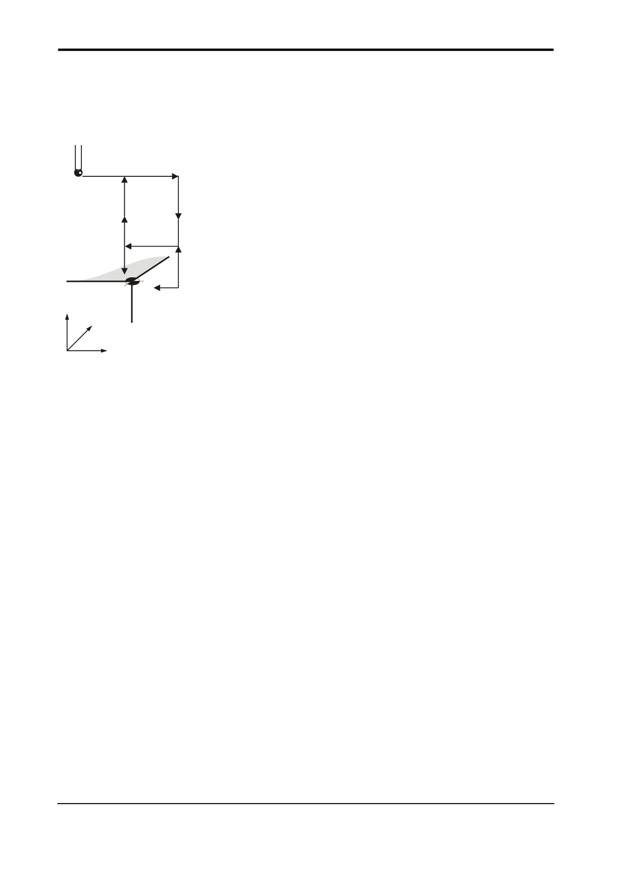
Figure 7.2
9.
G65P9811Z0T11
Single surface measure.
Probe movements
10.
G65P9810Z100.
Protected positioning move.
11.
G65P9833
Spin the probe off (where applicable).
12.
G28Z100.
Reference return.
continue
The tool radius offset (10) is updated by the error of surface position.
Publication No. H-2000-6222