FANUC DAEWOO CNC PROGRAM MANUAL - page 1
TRAINING
Forward
Thank you very much for participating in our education.
DAEWOO constantly makes an effort to research and develop to satisfy the
requirements of customers positively.
DAEWOO does its utmost to accept and practice the Quality Confirmation of DAEWOO and Custom-
ers' requirements through the Dealer-net-work of about 350 as practicing the World Quality Manage-
ment.
DAEWOO provides with the technical data and support the technical coaching, therefore, if you con-
tact us when you need of them , we will immediately help you.
We will do our best during your education period.
Thank you.
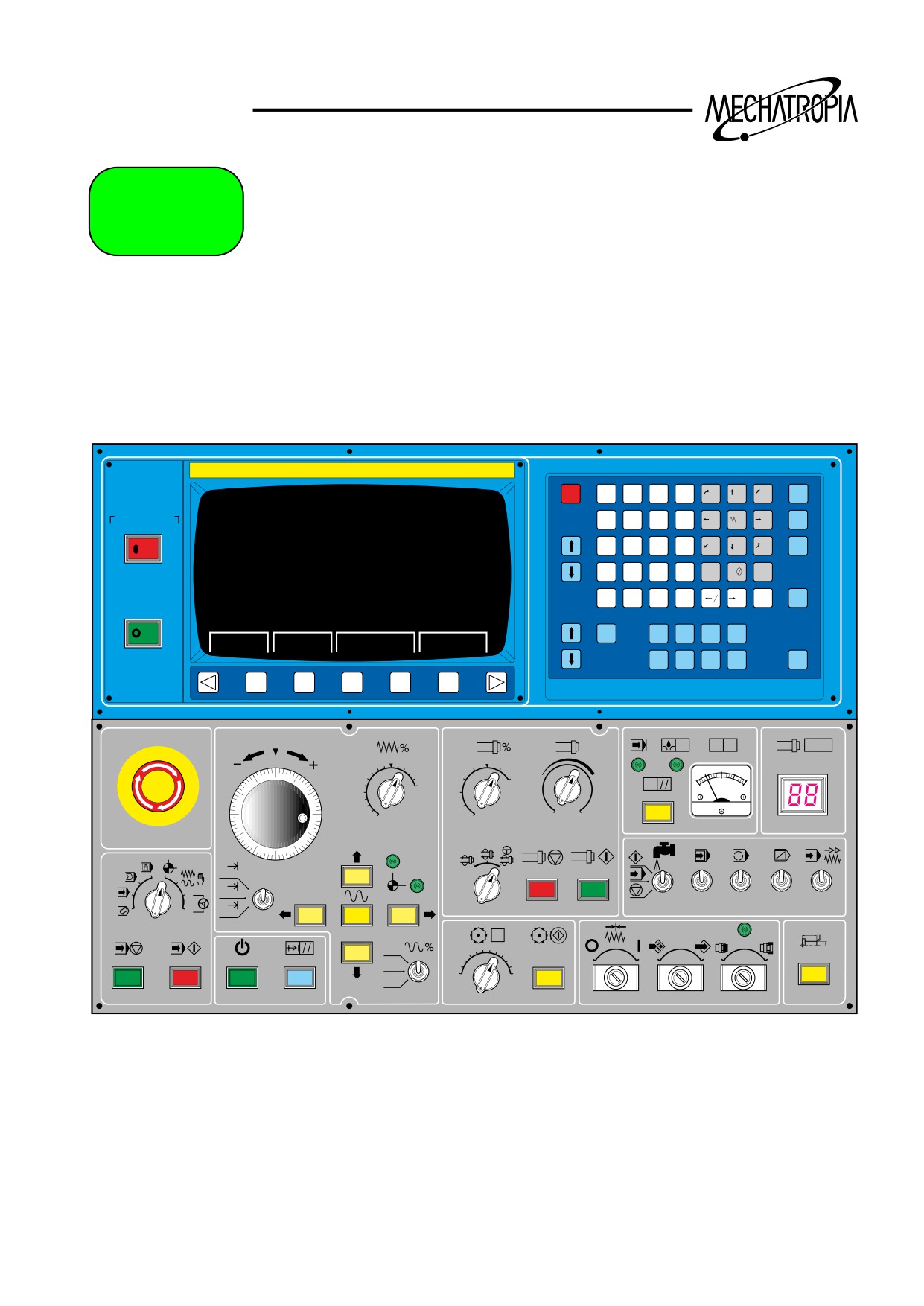
TRAINING
O-T
DAEWOO
RESET
O(
N)
GE
RC
7
8
9
ALTER
NO.
X
Z
R
G 01
0.000
0.000
0.000
NC POWER
G 02
0.000
0.000
0.000
XU
YV
ZW
4
TH
4
5
6
INSRT
G 03
0.000
0.000
0.000
CURSOR
G 04
0.000
0.000
0.000
I
JA
F
DELET
ON
,
K@
-NO
1
2
3
G 05
0.000
0.000
0.000
G 06
0.000
0.000
0.000
_
M#
S=
L+
G 07
0.000
0.000
0.000
T*
ACT. POSITION(RELATIVE)
P[
Q]
DH
BSP
EOB
CAN
INPUT
U
0.000
W
0.000
NUM.
MZ
120.
S
0T
PAGE
MDI
OFF
SHIFT
POS
PRGRM
OFSET
MENU
WEAR
GEOM
W.SHIFT
MRCRO
DGNOS
OPR
AUX
MACRO
OUTPT
PARAM
ALARM
GRAPH
START
?
? N
LM
80
100
120
90
100
110
50
100
150
60
140
80
120
0
180
150
?
%
40
70
20
60
0
50
SPINDLE LOAD
ALARM NO.
FEEDRATE OVERRIDE
EMERGENCY STOP
SPINDLE OVERRIDE
SPINDLE SPEED
+X
X100
X
X10
SINGLE
OPTIONAL
OPTIONAL
-Z
+Z
DRY RUN
Z
X1
S
TART
STOP
COOLANT
BLOCK
STOP
BLOCK SKIP
MODE
INCREMENTAL FEED
RAPID
β
N
6
7
α
100
4
5
3
8 910
50
2
11
–X
1
12
F0
CYCLE START FEED HOLD
MACHINE READY EMG. RELEASE
RAPID OVERRIDE
TOOL NO.
M
ACHINE LOCK
P
ROGRAM PROTECT
CHUCKING
1
TRAINING
G-FUNCTION
STANDARD G
SPECIAL
GROUP
FUNCTION
CODE
G CODE
#G00
G00
01
Positioning (Rapid feed)
G01
G01
Straight interpolation
G02
G02
Circular interpolation (CW)
G03
G03
Circular interpolation (CCW)
G04
G04
00
Dwell
G20
G20
06
Data input (inch)
#G21
G21
Data input (mm)
#G22
G22
04
Stored distance limit is effective
G23
(Spindle interference check ON)
G23
Stored distance limit is ineffective
(Spindle interference check OFF)
G27
G27
00
Machine reference return check
G28
G28
Automatic reference return
G29
G29
Return from reference
G30
G30
Tte 2nd rererence return
#G32
G33
01
Thread process
G40
G40
07
Cancel of compensation
G41
G41
Compensation of the left
G42
G42
Compensation of right
G50
G92
00
Creation of virtual coordinate/Setting the rotating time of principal spindle
G70
G70
Compound repeat cycle(Finishing cycle)
G71
G71
Compound repeat cycle(Stock removal in turning)
G72
G72
Compound repeat cycle(Stock removal in facing)
G73
G73
Compound repeat cycle(Pattern repeating cycle)
G74
G74
Compound repeat cycle(Peck drilling in Z direction)
G75
G75
Compound repeat cycle(Grooving in X direction)
G76
G76
Compound repeat cycle(Thread process cycle)
G90
G77
01
Fixed cycle(Process cycle in turning)
G92
G78
Fixed cycle(Thread process cycle)
G94
G79
Fixed cycle(Facing process cycle)
G96
G96
02
Control the circumference speed uniformly(mm/min)
#G97
#G97
Cancel the uniform control of circumference speed.
Designate r.p.m
G98
G94
05
Designate the feedrate per minute(mm/min)
#G99
#G95
Designate the feedrate per the rotation of principal spindle(mm/rev.)
-
G90
03
Absolute programming
-
G91
Incremental programming
Note) 1. # mark instruction is he modal indication of initial condition which is immediately available
when power is supplied.
2. In general, the standard G code is used in lathe, and it is possible to select the special G code
according to setting of parameters.
2
TRAINING
NC LATHE M-CODE LIST
M-CODE
DESCRIPTION
REMARK
M-CODE
DESCRIPTION
REMARK
M00
PROGRAM STOP
M39
STEADY REST 1 UNCLAMP
OPTION
M01
OPTIONAL STOP
M40
GEAR CHANGE NETURAL
M02
PROGRAM END
M41
GEAR CHANGE LOW
M03
MAIN-SPINDLE FORWARD
M42
GEAR CHANGE MIDDLE
M04
MAIN-SPINDLE REVERSE
M43
GEAR CHANGE HIGH
M05
MAIN-SPINDLE STOP
M46
PTS BODY UNCL & TRACT-BAR ADV.
OPTION
M07
HIGH PRESSURE COOLANT ON
OPTION
M47
PTS BODY CL & TRACT-BAR RET.
OPTION
M08
COOLANT ON
M50
BAR FEEDER COMMAND 1
OPTION
M09
COOLANT OFF
M51
BAR FEEDER COMMAND 2
OPTION
M10
PARTS CATCHER ADVANCE
OPTION
M52
SPLASH GUARD DOOR OPEN
OPTION
M11
PARTS CATCHER RETRACT
OPTION
M53
SPLASH GUARD DOOR CLOSE
OPTION
M13
TURRET AIR BLOW
OPTION
M54
PARTS COUNT
OPTION
M14
MAIN-SPINDLE AIR BLOW
OPTION
M58
STEADY REST 2 CLAMP
OPTION
M15
AIR BLOW OFF
OPTION
M59
STEADY REST 2 UNCLAMP
OPTION
(ONLY)
M17
MACHINE LOCK ACT
M61
SWITCHING LOW SPEED (N.J)
α
P60
MDI
(ONLY)
M18
MACHINE LOCK CANCEL
M62
SWITCHING HIGH SPEED (N.J)
α
P60
MDI
M19
MAIN-SPINDLE ORIENTAION
OPTION
M63
MAIN-SPDL CW & COOLANT ON
M24
CHIP CONVEYOR RUN
OPTION
M64
MAIN-SPDL CCW & COOLANT OFF
M25
CHIP CONVEYOR STOP
OPTION
M65
MAIN-SPDL & COOLANT OFF
M30
PROGRAM END & REWIND
M66
DUAL CHUCKING LOW CLAMP
OPTION
M31
INTERLOCK BY-PASS(SPDL &T/S)
M67
DUAL CHUCK HIGH CLAMP
OPTION
M32
INTERLOCK BY-PASS(SPDL &S/R)
3 AXIS
M68
MAIN-CHUCK CLAMP
M33
REV.-TOOL-SPINDLE FORWARD
3 AXIS
M69
MAIN-CHUCK UNCLAMP
M34
REV.-TOOL-SPINDLE REVERSE
M70
DUAL TAILSTOCK LOW ADVANCE
OPTION
M35
REV.-TOOL-SPINDLE STOP
M74
ERROR DETECT ON
M38
OPTION
M75
ERR0R DETECT OFF
3
TRAINING
NC LATHE M-CODE LIST
M-CODE
DESCRIPTION
REMARK
M-CODE
DESCRIPTION
REMARK
M76
CLAMFERING ON
M131
INTERLOCK BY-PASS (SUB-SPDL)
M77
CLAMFERING OFF
M163
SUB-SPDL CW & COOLANT ON
M78
TAILSTOCK QUILL ADVANCE
M164
SUB-SPDL CCW & COOLANT OFF
M79
TAILSTOCK QUILL RETRACT
M165
SUB-SPDL & COOLANT STOP
M80
Q-SETTER SWING ARM DOWN
OPTION
M168
SUB-CHUCK CLAMP
M81
Q-SETTER SWING ARM UP
OPTION
M169
SUB-CHUCK UNCLAMP
M84
TURRET CW ROTATION
M203
FORWARD SYNCHRONOUS COM.
M85
TURRET CCW ROTATION
M204
REVERSE SYNCHRONOUS COM.
M86
TORQUE SKIP ACT
B AXIS
M205
SYNCHRONOUS STOP
M87
TORQUE SKIP CANCEL
B AXIS
M206
SPINDLE ROTATION RELEASE
M88
SPINDLE LOW CLAMP
M89
SPINDLE HIGH CLAMP
M90
SPINDLE UNCLAMP
M91
EXTERNAL M91 COMMAND
3 AXIS
M92
EXTERNAL M92 COMMAND
3 AXIS
M93
EXTERNAL M93 COMMAND
M94
EXTERNAL M94 COMMAND
OPTION
M98
SUB-PROGRAM CALL
OPTION
M99
END OF SUB-PROGRAM
OPTION
M103
SUB-SPINDLE FORWARD
M104
SUB-SPINDLE REVERSE
M105
SUB-SPINDLE STOP
M110
PARTS CATCHER ADVANCE(SUB)
OPTION
M111
PARTS CATCHER RETRACT(SUB)
OPTION
M114
SUB-SPINDLE AIR BLOW
OPTION
M119
SUB-SPINDLE ORIENTATION
OPTION
4
TRAINING
Note) 1. M00 : For this command, main spindle stop, cutting oil, motor stop, tape reading stop are
carriedout.
M01 : While this function is the same as M00, it is effective when the optional stop switch of
console is ON.
This command shall be overrided if the optional stop switch is OFF.
M02 : Indicates the end of main program.
M30 : This is the same as M02 and it returns to the starting position of the programme when
the memory and the tape are running.
2. M code should not be programmed in the command paragraph containing S code or T code.
It is favorable for M code to programe in a command paragraph independently.
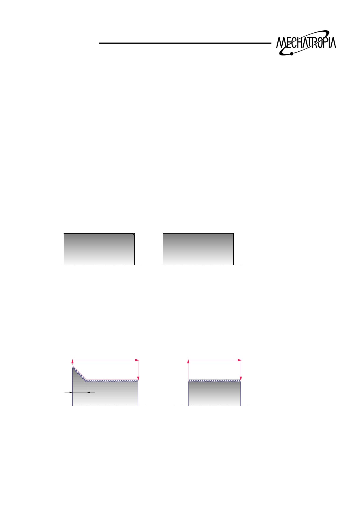
3. The edges of processed material become round due to the effect of characteristics of AC
servo motor. To avoid it, M74 and M75 functions are used.
When command of M75
When command of M74
(Error detection is OFF)
(Error detection is ON)
4. M76, M77
These codes are effective when thread process is programmed by G92, and they are used for
ON and OFF of thread beveling. Thread chamferingis set as much as one pitch by setting of
parameters and it is possible to set double.
(Thread chamferingON)
(Thread chamferingOFF)
5
TRAINING
Function
Address
Meaning of address
Program number
O(EIA)/(ISO)
Program number
Block sequence number
N
Sequence number
Preparatory function
G
Sercifies a motion mode (Linear, arc, etc)
Dimension word
X, Z
Command of moving position(absolute type) of each axis
U, W
Instruction of moving distance and direction(incremental type)
I, K
Ingredient of each axis and chamfering volume of circulat center
R
Radius of circle, corner R, edge R
Feed function
F, E
Designation of feedrate and thread lead
Auxiliary function
M
Command of ON/OFF for operating parts of machine
Spindle speed function
S
Designation of speed of main spindle or rotation time of main spindle
Function (Tool)
T
Designation of tool number and tool compensation number
Dwell
P, U, X
Designation of dwell time
Dewignation of program number
P
Designation of calling number of auxiliary program
Designation of sequence No
P, Q
Callling of compound repeat cycle, end number
Number of repetitions
L
Repeat time of auxiliary program
Parameters
A, D, I, K
Parameter at fixed cycle
One block is composed as follows
One block
N
G
X Y
F
S
T
M
:
Sequence Preparation
Dimension
Feed
Spindle
Tool
Function
EOB
Auxiliary
function
word
function
speed
function
auxiliary
No.
function
6
TRAINING
Meaning of Address
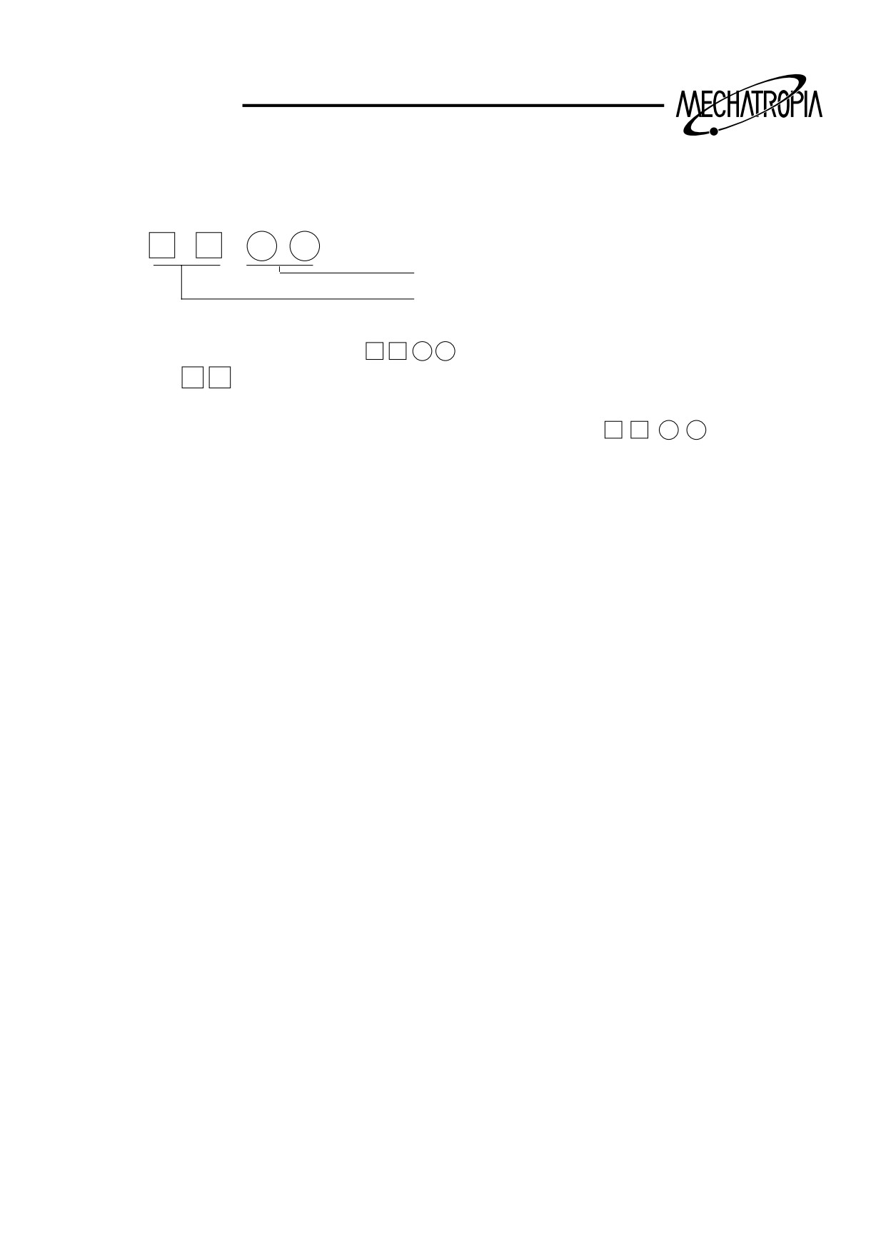
T function is used for designation of tool numbers and tool compensation.
T function is a tool selection code made of 4 digits.
T
0
2
0
2
Designation of tool compensation number
Designation of tool number
Example) If it is designated as(T
0
2
0
2 )
0
2
calls the tool number and calls the tool compensation value of number , and
the tool is compensation as much as momoried volume in the storage.
The cancel of tool compensation is commanded as T
0
0
If you want to call the next tool and compensation, you should cancel the tool com-
pensation. For convenient operation, it is recommended to used the same number of
tool and compensation.
It is not allowed to use the same tool compensation number for 2 different tools.
Minimum compensation value : + 0.001mm
Maximum compensation value : + 999.999mm
Tool compensation of X spindle is designated as diameter value.
7
TRAINING
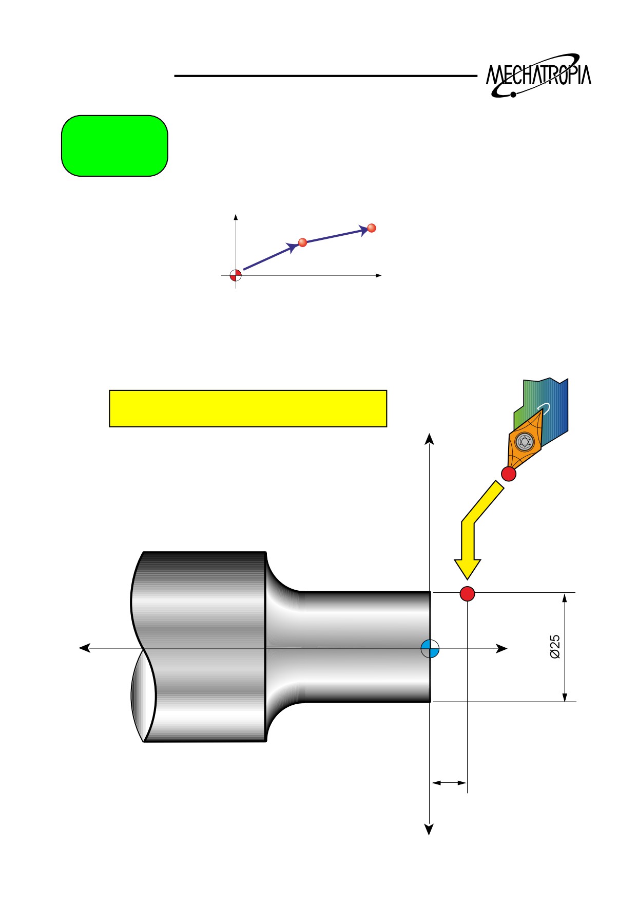
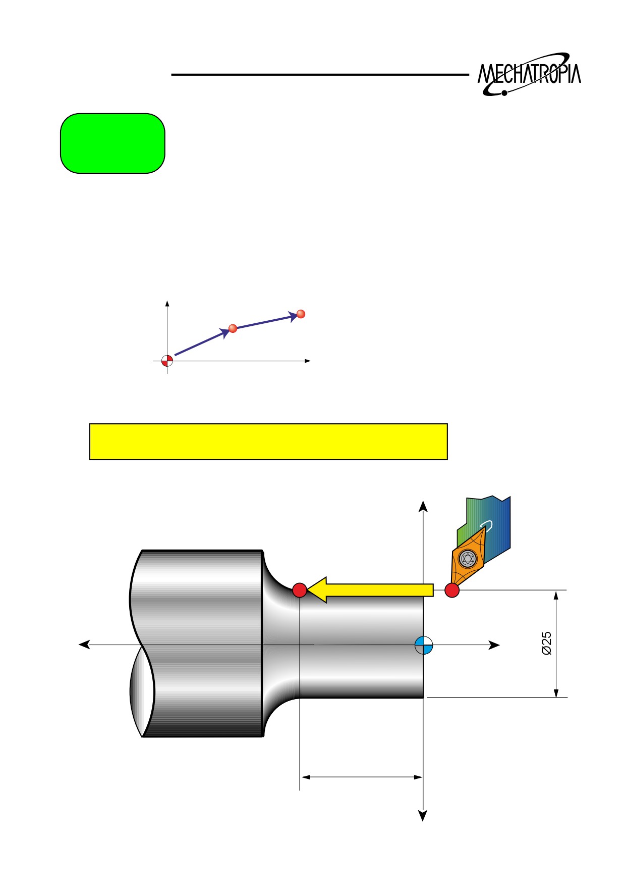
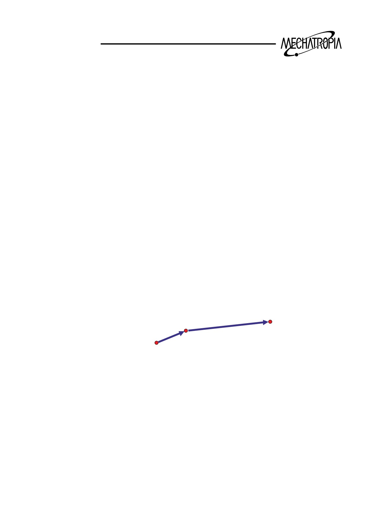
G00(Positioning)
Each axes moves as much as commanded data in rapid feedrate.
G00
G00 X150.0 Z100.0
G00
X(U)
Z(W);
X200.0 Z200.0
X
X200
X150
Z200
G00 U150.0 W100.0
Z100
Z
U50.0 W100.0
(X0 Z0)
N1234 G00 X25. Z5.
+X
G00
-Z
+Z
5
-X
8
TRAINING
G01
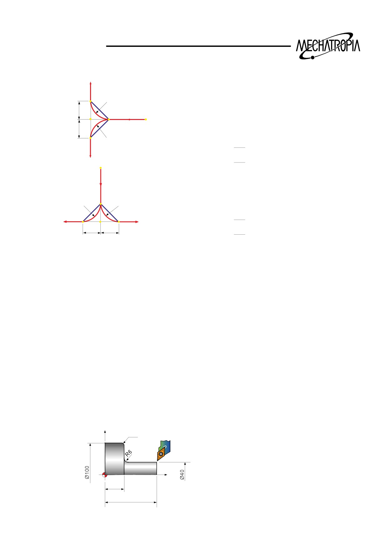
G01(Linear interpolation)
Each axes moves straigrtly as much as commanded data in commanded rate.
G01 X150.0 Z100.0 F0.2 :
G01
X(U)
Z(W)
F
X200.0 Z200.0 :
X
X200
G01 U150.0 W100.0 F0.2 :
X150
Z200
Z100
U50.0 W100.0 :
Z
(X0 Z0)
N1234 G01 X25. Z-30. F0.2
+X
G01
-Z
+Z
30
-X
9
TRAINING
AUTO CHAMFERING “C” AND CORNER “R” (Option)
+X
C
+r
+i
A
B
-i
Command path Z→X : A : Start point of instuction
-r
C'
G01 Z(w) B C ( ¡ i) : B : End point of instruction
-X
G01 Z(w) B C ( ¡ r) :CC’ : Running point of command
A
Command path X→Z :
-r
+r
-Z
+Z
G01 X(u) B C ( ¡ k)
C'
B
C
-K
+K
G01 X(u) B R ( ¡ r)
Note) (1) After instructing from G01 to one axis, the next command paragraph should be fed in
vertical direction.
(2) If the next command paragraph is incremental type, designate the incremental volume
baed on B point.
(3) In following cases, errors occur. (G01 Mode)
– When instruction one of I, K, R and X and Z at the same time.
– When instructing two of I, K, R in the same block.
– When instructing Xand I or Z and K.
– When the moving distance is less than the next command
are not right angled.
(4) During the operation of single command paragraph, the operation at C point stops.
Example)
X
C3
N1 G01 Z30.0 R6.0 F0.2 :
N3
N2
N2 X100.0 K-3.0 :
N1
N3 Z0 :
Z
(N2 X100.0 C3.0 :)Normal
30
80
10
TRAINING
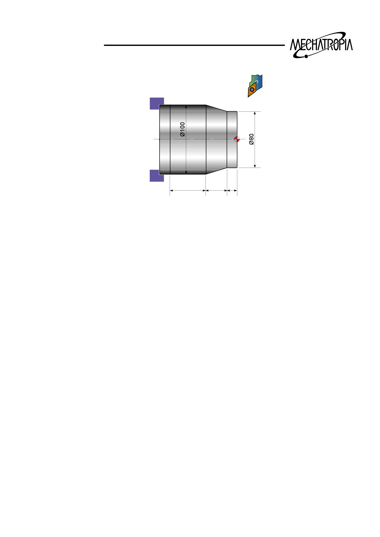
G01 PROGRAM
Example1)
50
30
15
O0001 :
N10 G50 S1500 T0100 M42 :
N20 G50 S2000 T0300 :
G96 S180 M03 :
G96 S200 M03 :
G00 X100.5 Z5.0 T0101 M08 :
G00 X85.0 Z5.0 T0303 M08 :
G01 Z-95.0 F0.25 :
Z0 :
G00 U2.0 Z0.5 :
G01 X-1.6 F0.2 :
G01 X-1.6 F0.2 :
G00 X80.0 Z3.0 :
G00 X95.0 W1.0 :
G42 Z1.0 :
G01 Z-37.3 F0.25 :
G01 Z-15.0 F0.18 :
X100.0 Z-45.5 :
X100.0 Z-45.0 :
G00 Z1.0 :
Z-95.0 :
X90.0 :
G40 U2.0 W1.0
G01 Z-29.8 :
G00 X200.0 Z200.0 M09 T0300 :
X95.0 Z-37.3 :
M30 :
G00 Z1.0 :
X85.0 :
G50 : Setting the rotating time of max. speed of
G01 Z-22.3 :
main spindle
X90.0 Z-29.8 :
G96 : Constant surface speed control command
G00 Z1.0 :
G40 : Compensation cancel
X80.5 :
G42 : Right hand compensation
G01 Z-15.55 :
X85.0 Z-22.3 :
G00 X200.0 Z200.0 M09 T0100 :
M01 :
11
TRAINING
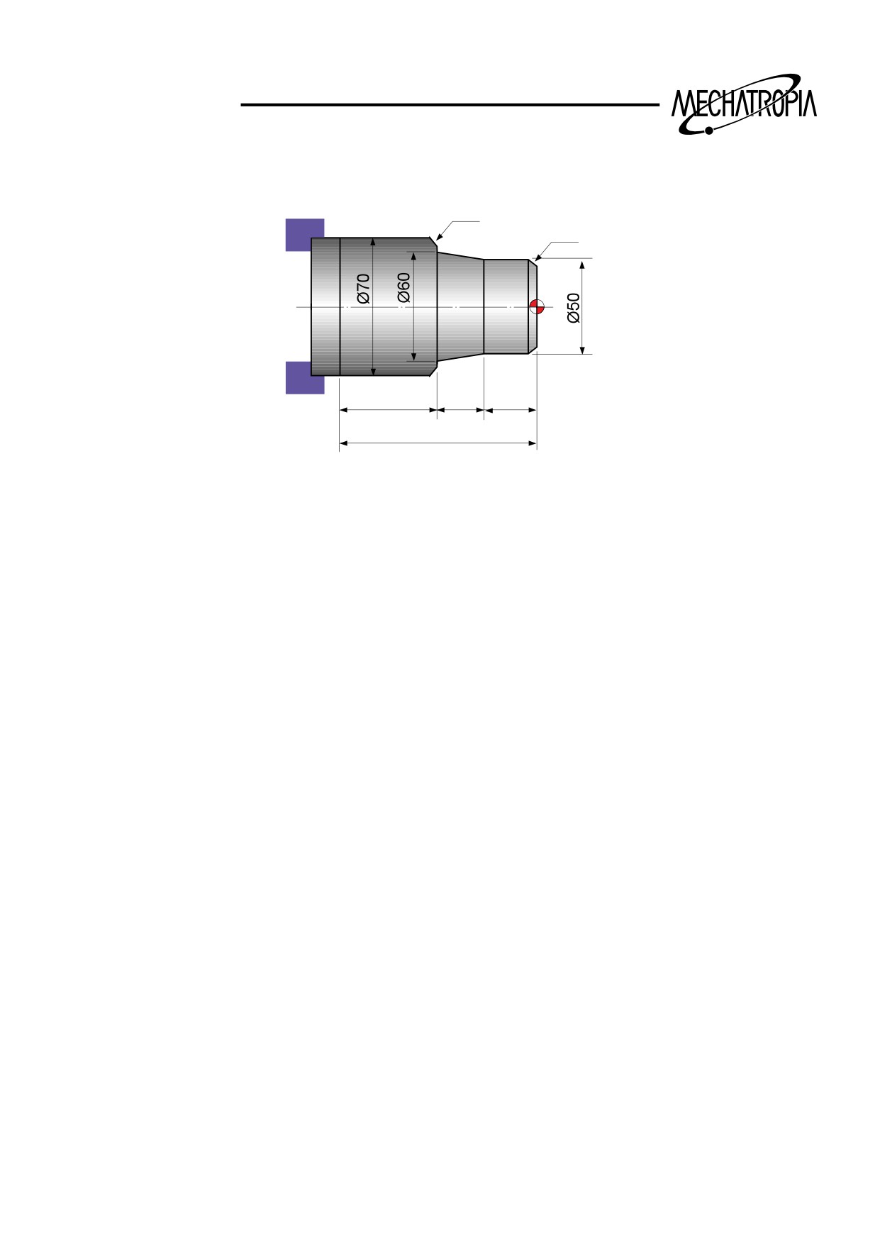
G01 PROGRAM
Example2)
C1
C1
45
25
30
100
G01 Z-30.0 :
O0002 :
X60.3 Z-54.7 :
N10 G50 S2000 T0100 :
X72.0
G96 S180 M03 :
G00 X150.0 Z200.0 T0100 :
G00 X70.5 Z5.0 T0101 M08 :
M01 :
G01 Z-100.0 F0.25 :
N20 G50 S2300 T0300 :
G00 U2.0 Z0.5 :
G96 S200 M03 :
G01 X-1.6 F0.23 :
G00 X55.0 Z5.0 T0303 M08 :
G00 X65.0 W1.0 :
Z0 :
G01 Z-54.5 F0.25 :
G01 X-1.6 F0.2 :
G00 U2.0 Z1.0 :
G00 X46.0 Z3.0 :
X60.0 :
G42 Z1.0 :
G01 Z-54.5 :
G01 X50.0 Z-1.0 F0.15 :
Z-30.0 :
G00 U2.0 Z1.0 :
X60.0 Z-55.0 :
X55.0 :
X68.0 :
G01 Z-30.0 :
X70.0 W-1.0 :
X60.0 Z-54.5 :
Z-100.0 :
G00 U2.0 Z1.0 :
G40 U2.0 W1.0
X50.5 :
G00 X150.0 Z200.0 M09 T0300 :
M30 :
12
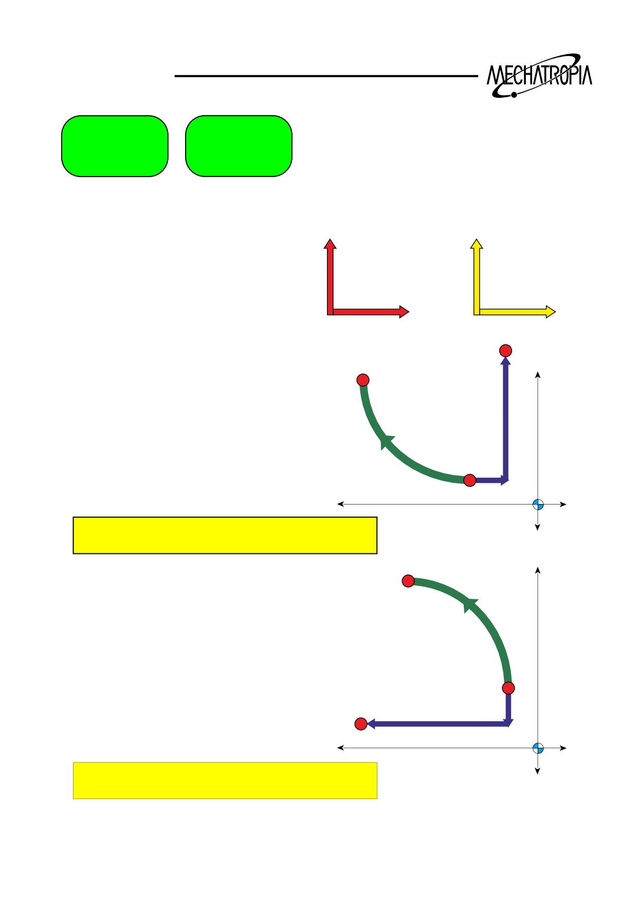
TRAINING
G02
G03
X
I (X)
Z
K(Z)
P0
P2
X
I
G02
P1
K
Z
N1234 G02 X.. Z.. (R..)
X
P2
G03
P1
P0
- I
- K
Z
N1234 G03 X.. Z.. (R..)
13
TRAINING
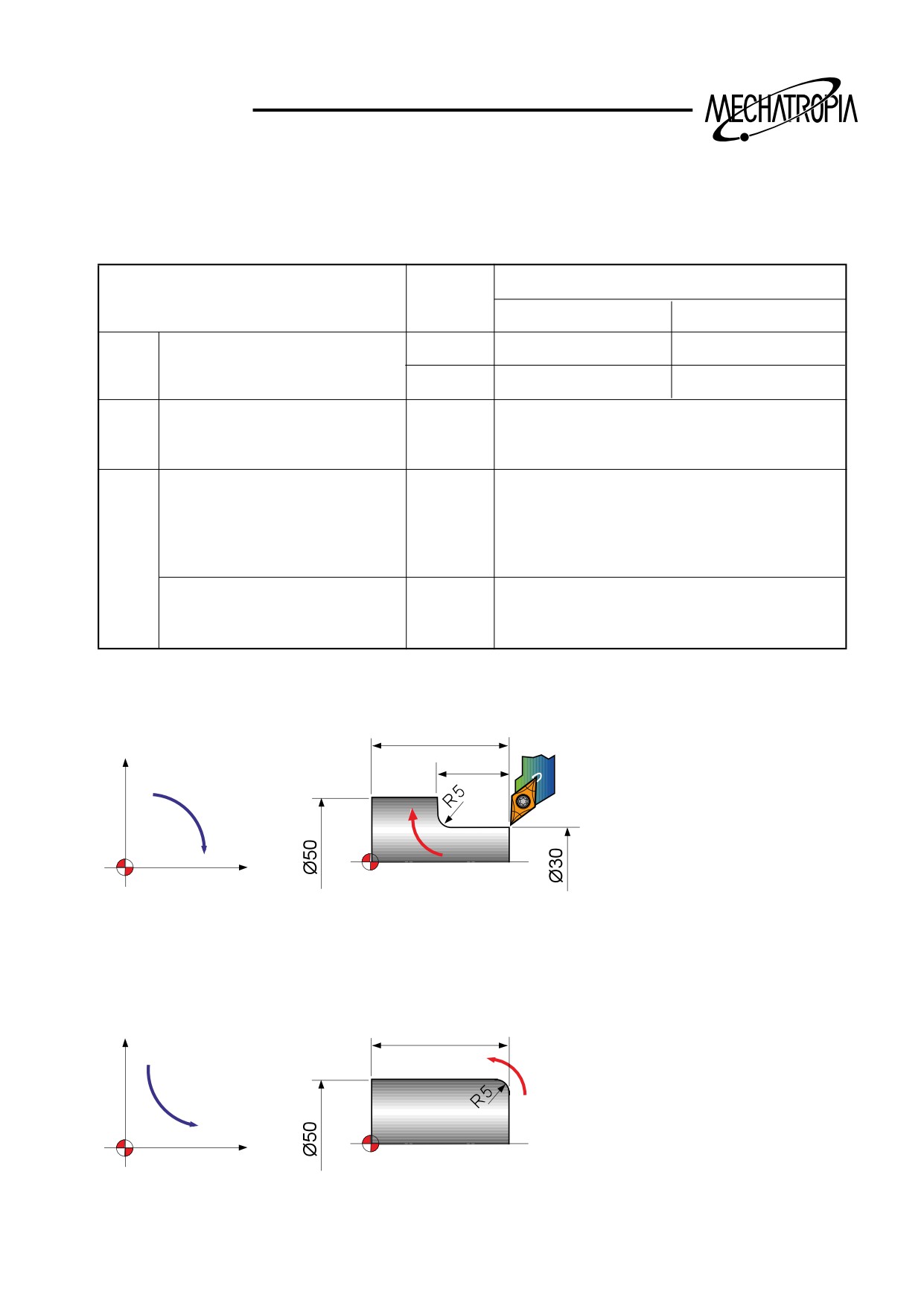
G02, G03(Circular interpolation)
Each axis interpolates circularly to the commanded coordinate in instructed speed.
Meaning
Conditions
Instruction
Right hand coodinate
Left hand coodinate
1
Rotation direction
G02
CW
CCW
G03
CCW
CW
2
Location of end point
X,Z
Location X,Z of commanded point from coordinate
Distance to the end point
U,W
Distance from start point to commanded point
3
Distance between start point
Distance from start point to the center of and arc
and the center point
I,K
with sign, radius value (I always designates the
radius)
Arc radius with no sign radius
R
Radius of circumference
of circumference
G02 X(u) Z(w) R_ F_ :
60
G01 X30.0 Z60.0 F0.3 :
X
30
Z35.0 :
G02
G02 X40.0 Z30.0 I5.0 :
(G02 U10.0 W-5.0 I5.0)
G02
Z
G01 X50.0 :
Z0 :
G03 X(u) Z(w) R_ F_ :
G01 X40.0 Z60.0 F0.3 :
60
X
G03 X50.0 Z55.0 K-5.0 :
G03
G03
Z
14
TRAINING
Note) (1) If I or K is 0 it is omissible.
(2) G02 I_: Make a round of circle.
(3) It is recommended to use R as + value, and designates the circumferences less than
180.
G03 R_: No moving
(4) When designating R which is less than the half of moving distance, override R and make
half circle.
(5) When designating I, K and R at the same time, R is effective.
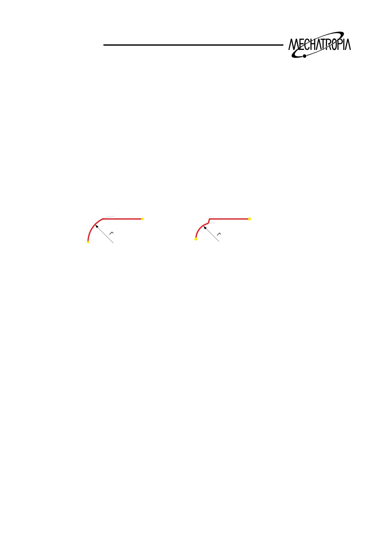
(6) When the moving end point is not on the circumference as a result of wrong designation
of and K :
P2
P2
P1
P1
15
TRAINING
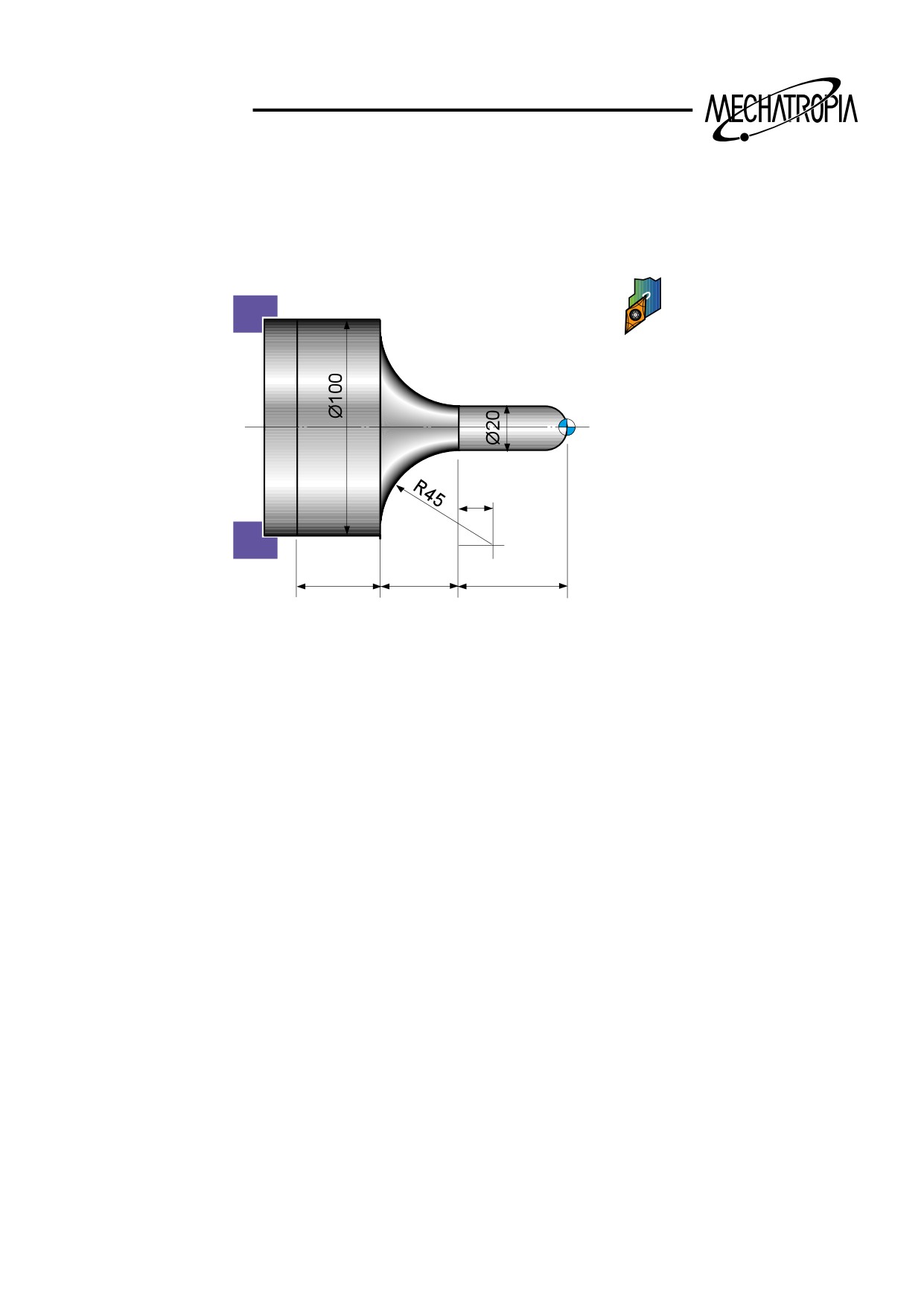
G03
PROGRAM
)
G02
Example 1)
20.615
40
24.385
50
N10
:
N20 G50 S2000 T0300 :
G96 S200 M03 :
G00 X0 Z3.0 T0303 M08 :
G42 G01 Z0 F0.2 :
G03 X20.0 Z-10.0 R10.0 :
G01 Z-50.0 :
G02 X100.0 Z-74.385 I40.0 K20.615 : (G02 X100.0 Z-74.385 R45.0)
G01 Z-125.0 :
G40 U2.0 W1.0
G00 X200.0 Z200.0 M09 T0300 :
M30 :
16
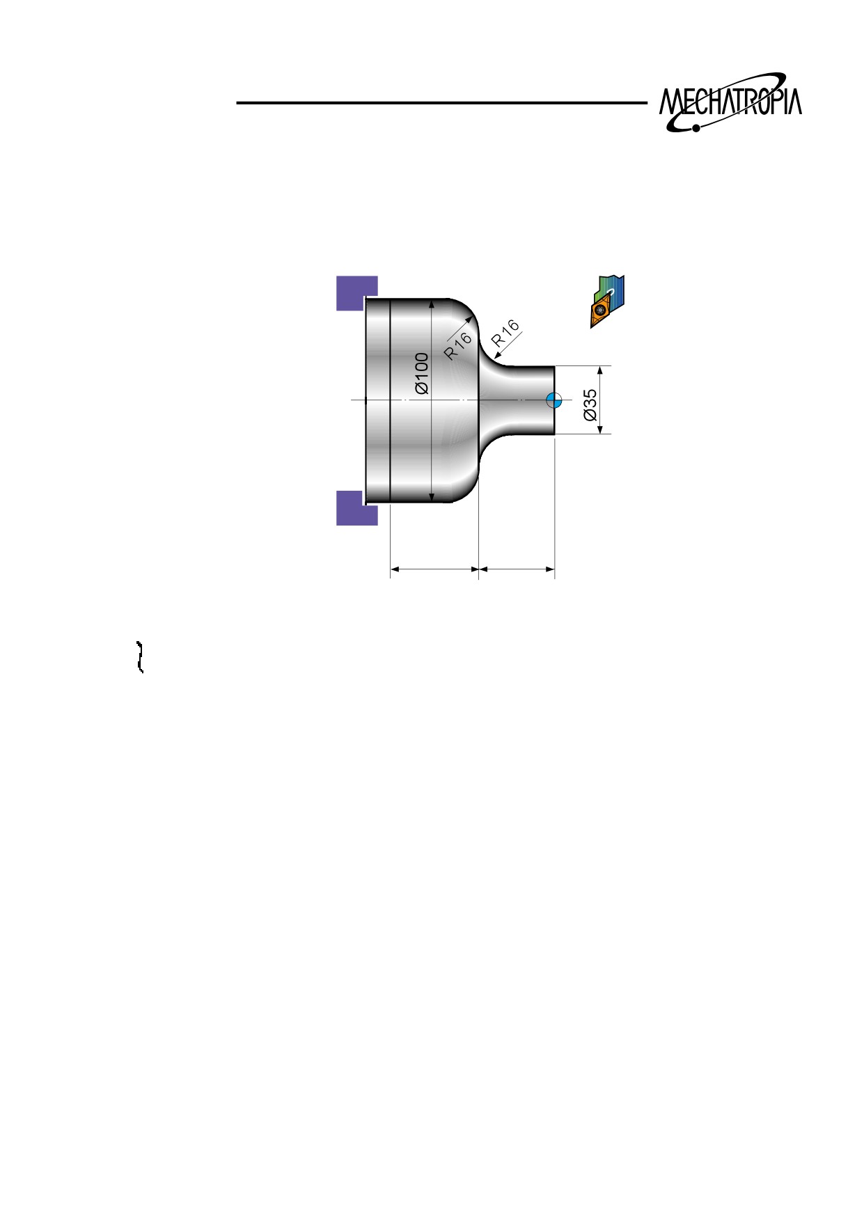
TRAINING
G02
PROGRAM
)
G03
Example 2)
46
36
N10
:
N20 G50 S2000 T0300 :
G96 S200 M03 :
G42 G00 X35.0 Z5.0 T0303 M08 :
G01 Z-20.0 F0.2 :
G02 X67.0 Z-36.0 R16.0 : (G02 X67.0 Z-36.0 I16.0 K0)
G01 X68.0 :
G03 X100.0 Z-52.0 R16.0 : (G02 X100.0 Z-52.0 I0 K-16.0)
G01 Z-82.0 :
G40 G00 X200.0 Z200.0 M09 T0300 :
M30 :
# When I and K instruction, if the data value is “0” it can be omitted.
17
TRAINING
G01
G02 ) PROGRAM
30
G03
15
2.5
15
24.33
8
42
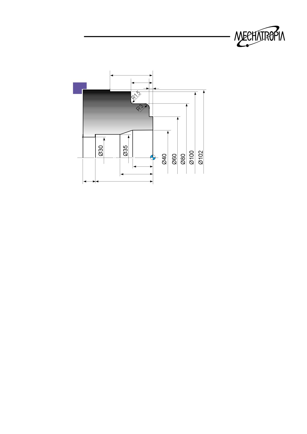
O0000 :
G01 Z-14.8 F0.27 :
N10 (ø30 DRILL)
G00 U2.0 Z1.0 :
G50 T0200 :
X80.5 :
G97 S250 M03 :
G01 Z-14.1 :
G00 X0 Z5.0 T0202 M08 :
G02 X81.9 Z-14.8 R0.7 :
G01 Z-5.0 F0.07 :
G00 X100.5 W1.0
W1.0 :
G01 Z-29.8
Z-40.0 F0.25 :
G00 U2.0 Z-1.0 :
G00 Z5.0 :
G01 X60.5 F0.23 :
Z-39.0 :
G00 X82.0 W1.0 :
G01 Z-60.0 :
Z-2.4 :
G00 Z10.0 :
G01 X60.5 :
X200.0 Z200.0 T0200 :
X72.9 :
M01 :
G03 X80.5 Z-6.2 R3.8 :
N20 (Outside diameter stock removal)
G00 U2.0 Z5.0 :
G50 S1500 T0100 :
X200.0 Z200.0 T0100 :
G96 S180 M03 :
M01 :
G00 X94.0 Z5.0 T0101 M08 :
G01 Z-14.8 F0.27 :
G00 U2.0 Z0.5 :
G01 X28.0 F0.23 :
G00 X87.0 W1.0 :
18
TRAINING
N30 (Inside diameter stock removal)
N50 (Inside diameter finishing)
G50 S1500 T0400 :
G50 S1800 T0600 :
G96 S180 M03 :
G96 S200 M03 :
G00 X34.5 Z3.0 T0404 M08 :
G00 X40.0 Z5.0 T0606 M08 :
G01 Z-41.8 F0.27 :
G41 Z1.0 :
G00 U-0.5 Z1.0 :
G01 Z-15.0 F0.2 :
X39.5 :
X35.0 Z-24.33 :
G01 Z-15.0 :
Z-42.0 :
X34.5 Z-24.3 :
X29.0 :
G00 Z10.0 :
G40 G00 Z10.0 :
X200.0 Z200.0 T0400 :
X200.0 Z200.0 T0600 M09 :
M01 :
M30 :
N40 (Out diameter finishing)
G50 S1800 T0500 :
G96 S200 M03 :
G00 X63.0 Z5.0 T0505 M08 :
Z0 :
G01 X38.0 F0.2 :
G00 X60.0 Z3.0 :
G42 Z1.0 :
G01 Z-2.5 F0.2 :
X74.0 :
G03 X80.0 Z-5.5 R3.0 :
G01 Z-13.5 :
G02 X83.0 Z-15.0 R1.5 :
G01 X100.0 :
Z-30.0 :
X103.0 :
G40 G00 U2.0 W1.0 :
G00 Z10.0 :
X200.0 Z200.0 T0500 :
M01 :
19
TRAINING
1G04 (Dwell)
After passing as much time as commanded by X(u) or P code in the same block, carry out the next
block.
In case of 10 seconds' dwell
G04 X10.0 : (G04 X10000 : )
G04 U10.0 : (G04 U10000 : )
G04 P10000.0 : (G04 P1000 : )
Automatic reference return
Reference means certain point fixed in the machine, and coordinate value of reference is set in NC
parameter.
OT-C/F
FS16/18T
Parameter NO
N708(X)
N1240(X, Z)
N709(Z)
1) G27(Reference return check)
Position is decided through rapid feed to the position of value set in NC PARAMETER by com-
mand.
Example) When PARAMETER N708(X) is 330000
N709(Z) is 529000
G00 X100.0 Z100.0 :
G27 X330.0 Z529.0 :
End point(Machine reference)
X330.0
(
)
Z529.0
( X100.0
)
Z100.0
Start point(0.0)
If arrived position is the reference, reference Lamp is ON.
Note) When instructing G27, you should cancel the OFFSET volume
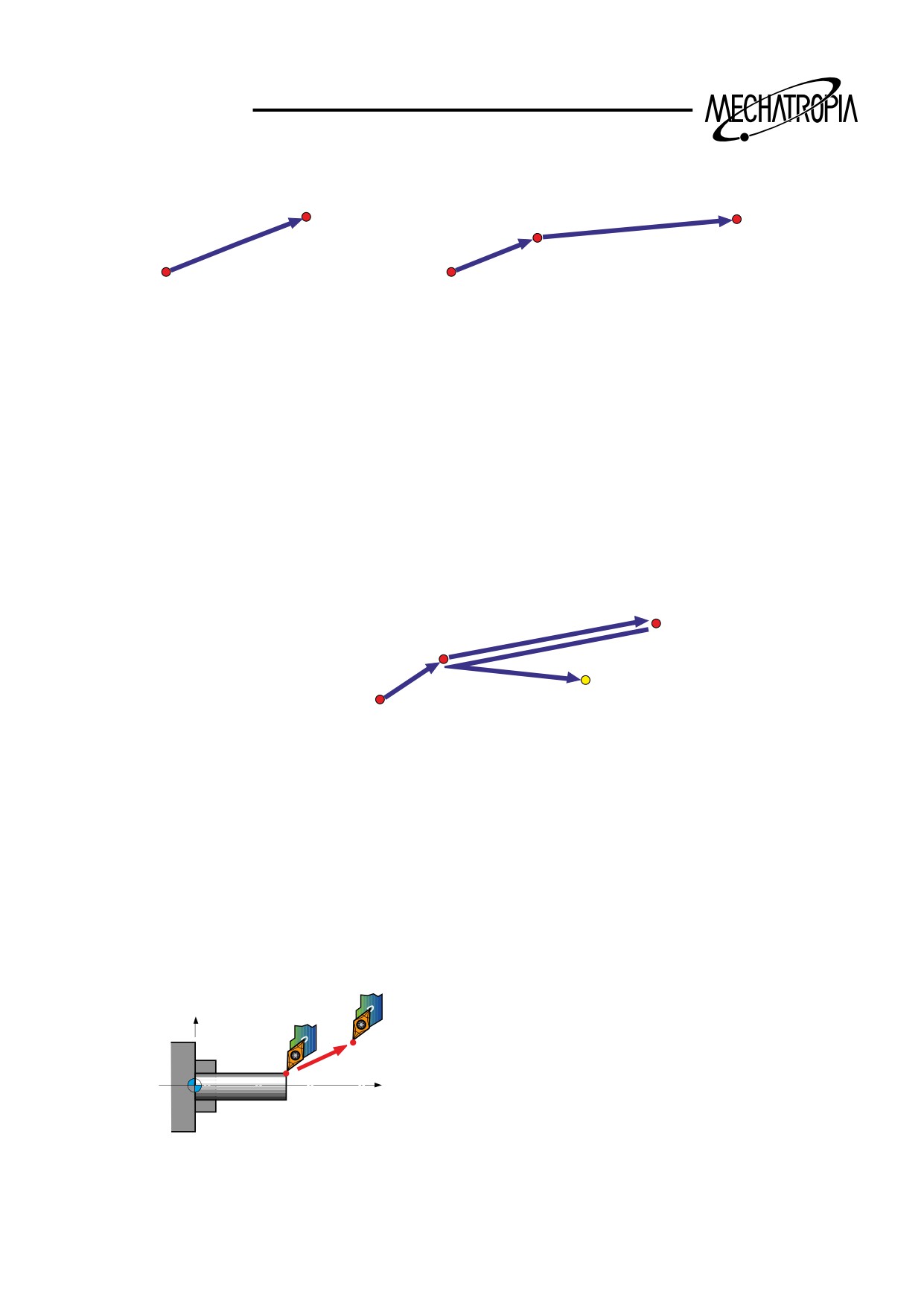
2) G28(Reference automatic return)
By command, commanded axis automatically returns to the reference.
G28 X(u) Z(w) :
Example) When PARAMETER N708(X) is 330000
N709(Z) is 529000
20
TRAINING
G28 U0 W0 :
G27 X100.0 Z100.0
( X330.0 )
( X330.0 )
Z529.0
Z529.0
( X100.0 )
Z100.0
Action of G28 block presents that the commanded axis goes via the center in rapid feedrate and
returns to the reference.
Note) When instructing G28 block, tool, tool compensation, tool location offset should be can-
celed principlly.
3) G29(Automatic return in reference)
Commanded spindle goes via the remoried center point and decides the position as com-
manded point.
G29 X(u) Z(w) :
∴Generally, it is used right after G28 or G30 command.
G28 X100.0 Z100.0 :
Machine referebce
Center point
G29 X50.0 Z200.0 :
Return point
X100.0
Z100.0
X50.0
Start point
Z200.0
4) G30(The 2nd reference return)
Commanded spindle automatically returns to the 2nd reference
(coordinate point set in parameter)
G30 X(u) Z(w)) :
∴You should input appropriate distance between works and tool exchangeposition in the relative
parameter.
PARAMETER NO N735(X) = 200000
FS16/18T
N736(Z) = 300000
N1241(X,Z)
The 2nd reference
X
X200.0
G30 U0 W0 :
Z300.0
Z
Reference) Generally, the 2nd reference is used for the start point of program.
21
TRAINING
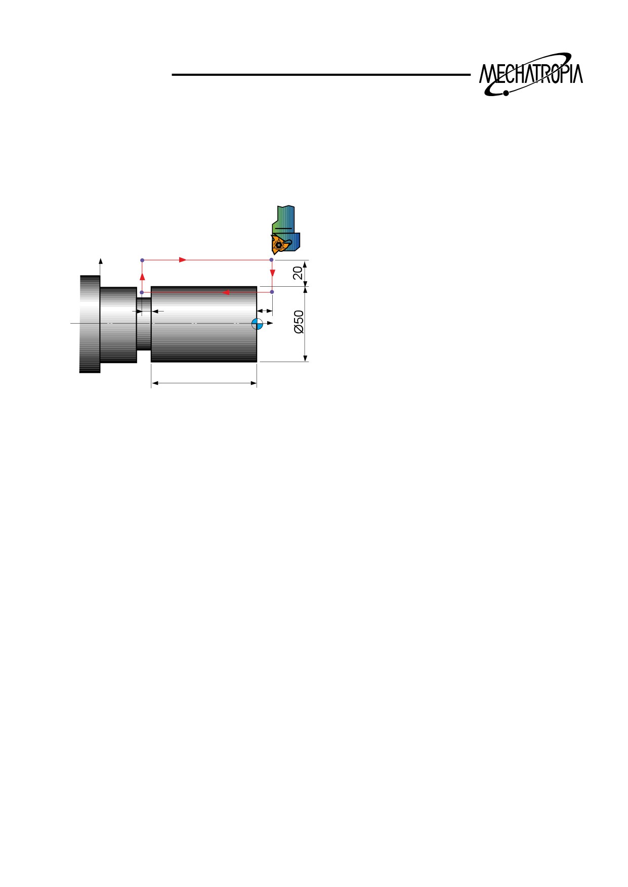
G32(THREAD CYCLE)
According to G32 command, straight thread and taper thread of certain lead are cut.
G32 Z(w) F : (G32 is applied to only single block)
X(u) F :
Example 1) STRAIGHT lead
Lead of screw : 3mm
X
δ1 : 5mm
δ2 : 1.5mm
δ2
δ1
Depth of cut : 1mm(2cut two times)
Z
70
(ABSOLUTE)
G50 T0100 :
G97 S800 M03 :
G00 X90.0 Z5.0 T0101 M8 :
X48.0 :
G32 Z-71.5 F3.0 :
G00 X90.0 :
Z5.0 :
X46.0 :
G32 Z-71.5 :
G00 X90.0 :
Z5.0
X150.0 Z150.0 T0100 :
M30 :
∗ When processing G32 thread, feed(pitch) is modal.
22
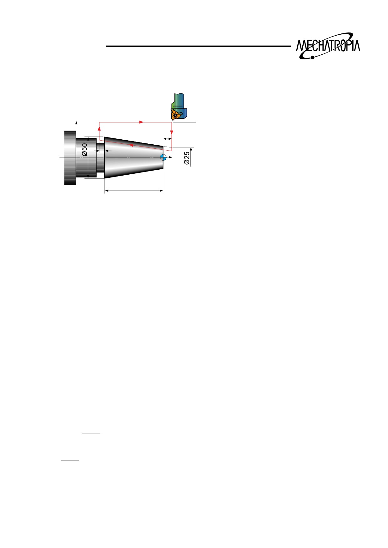
TRAINING
Example 1) STRAIGHT lead
G32 X(u) Z(w) F : Because it is taper, it is applied to both axis at the same time.
Lead of screw : 3mm
X
δ1 : 5mm
δ1
δ2 : 1.5mm
δ2
Depth of cut : 1mm(2cut two times)
Z
70
(ABSOLUTE)
(INCREMENTAL)
G50 S800 T0100 :
G50 S800 T0100 :
G97 S800 M03 :
G97 S800 M03 :
G00 X90.0 Z5.0 T0101 :
G00 X90.0 Z5.0 T0101 :
X22.026 :
U-67.974 :
G32 X49.562 Z-71.5 F3.0 :
G32 U27.321 W-76.5 F3.0 :
G00 X90.0 :
G00 U40.438 :
Z5.0 :
W76.5 :
X21.052 :
U-68.948 :
G32 X48.588 Z-71.5 :
G32 U27.321 W-76.5 :
G00 X90.0 :
G00 X90.0 :
Z5.0 :
W76.5 :
X150.0 Z150.0 T0100 :
X150.0 Z150.0 T0100 :
M30 :
M30 :
Reference)
Values of incomplete thread δ1 and δ2.
δ1= 3.6 x L x n
L = Lead of thread
1800
n = Rotating time of main spindle
δ2= L x n
1800
23
TRAINING
G42
-X
-Z
+Z
+X
+X
-Z
+Z
-X
24
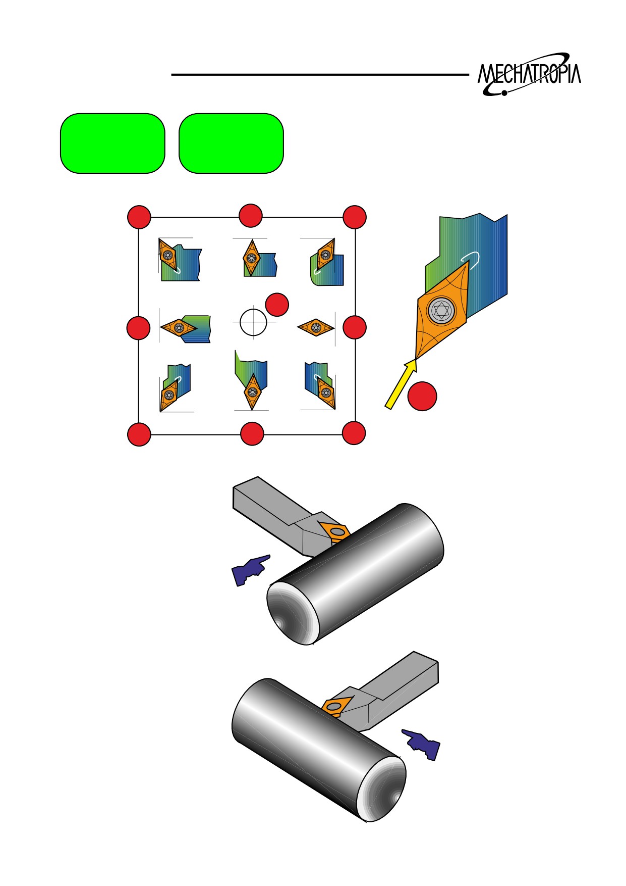
TRAINING
G41
G42
2
6
1
9
7
5
R
3
8
4
G41
G42
25
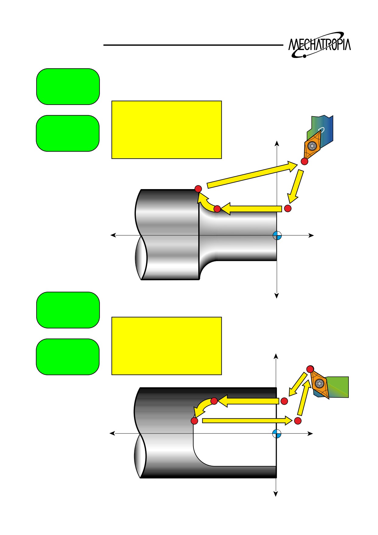
TRAINING
G40
N100 G42 G00 X.. Z..
N105 G01 Z-.. F..
G42
N110 G02 X.. Z-.. R..
+X
N115 G40 G00 X.. Z..
G40
N115
N100
G42
N110
N105
-Z
+Z
-X
G41
N100 G41 G00 X.. Z..
N105 G01 Z-.. F..
N110 G02 X.. Z-.. R..
+X
G40
N115 G40 G00 X.. Z..
-Z
+Z
-X
26
TRAINING
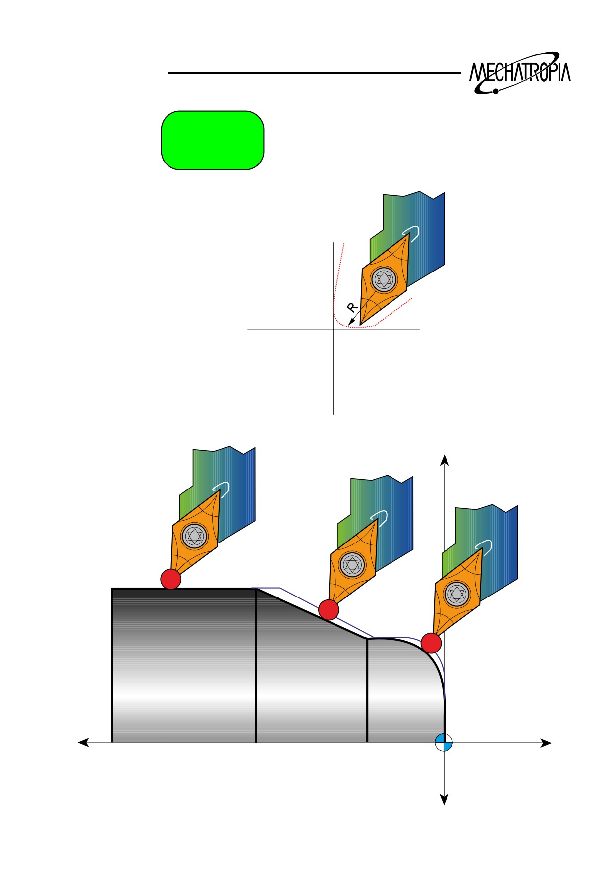
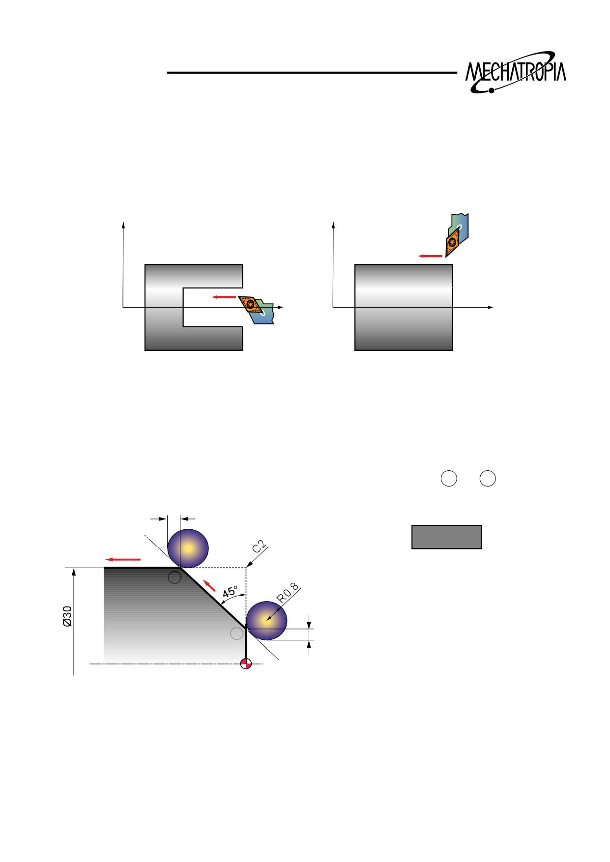
Tool diameter compensation
G40 : R compensation cancel
G41 : When located on the left side of material based on the progressing direction,
G42 : When located on the right side of material based on the progressing direction,
X
X
G41
G42
Z
Z
What is Tool diameter compensation?
If R is on the end of the tool edge, parts which are not impensated only by tool position OFFSET
are occured during the taper cutting or circlar cutting. Therefor, impensating this error automatically
is namelyR compensation.(During the tool diameter compensation, add theR and T-direction in the
R compensation column of OFFSET PAGE.
Example 1) When not using tool diameter compensation(R compensation a and b should be cal-
culated)
compensation ¡
0.5
PROGRAM
G01 X25.0 Z0 F0.2 :
b
X30.0 Z-2.5 :
G00 U1.0 Z1.0 :
compensation
G28 UO WO :
( ¡ 0 .5)
a
M30 :
∗
27
TRAINING
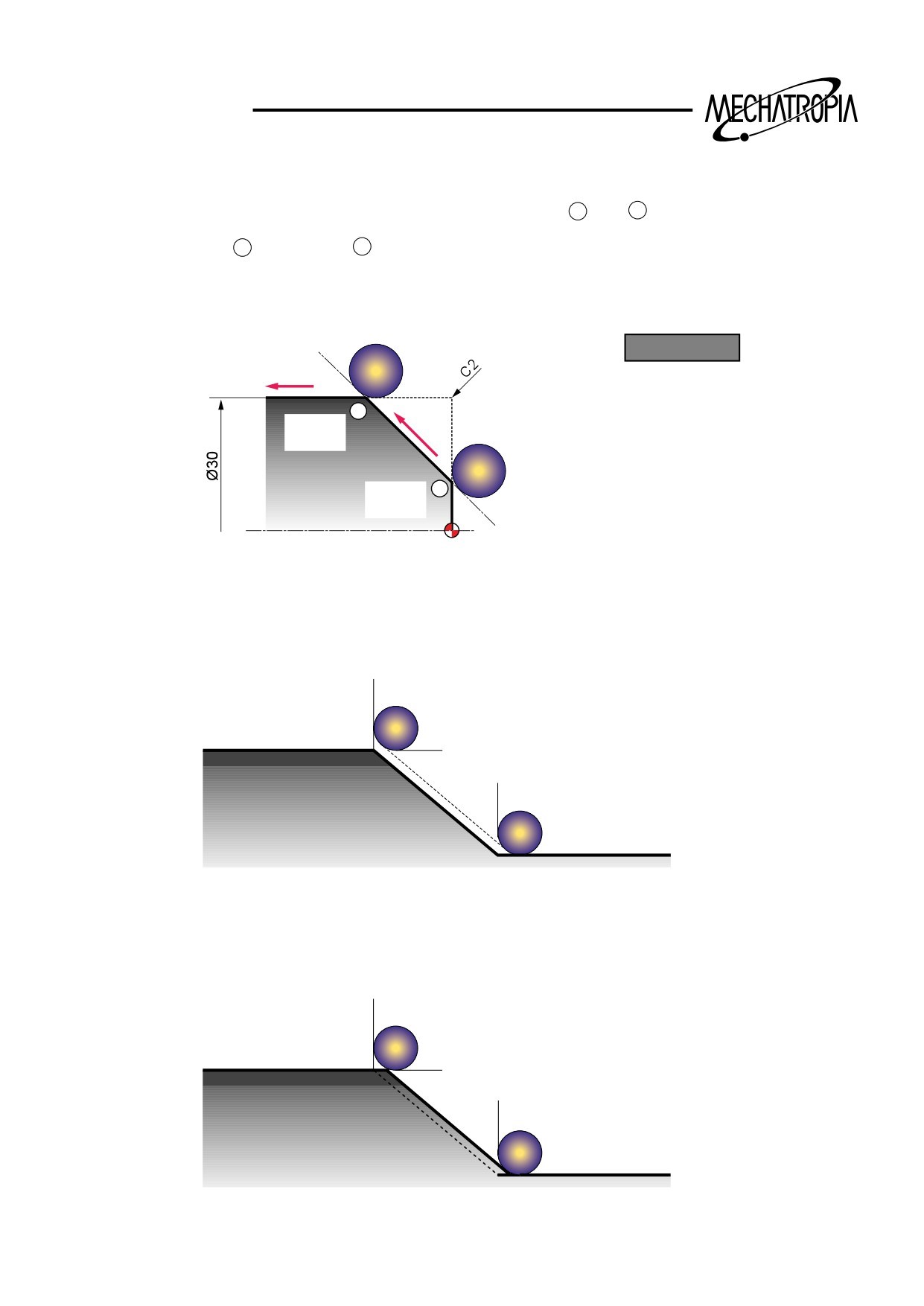
Example 2) When using tool diameter compensation
∗ You do not have to calculate R compensation a and b
∗ If a position and b position are given on the program, the tool performs automati-
cally R compensation and moves to the next progressing direction.
compensation ¡
0.5
PROGRAM
G42 X26.0 Z0 F0.2 :
compensation
b
G01 X30.0 Z-2.0 :
X = 30.0
( ¡ 0 .5)
Z = -2.0
Z-30.0 :
G00 U1.0 Z1.0 :
X = 26.0
a
Z = 0
G28 UO WO :
M30 :
∗
Presentation 1) In case of no compensation
Presentation 2) In case of compensation
28