FANUC I/O Unit–MODEL A CONNECTION AND MAINTENANCE MANUAL MARMGIOMA12801E REV. F (B-61813EN/06) - page 3
5.DIGITAL INPUT/OUTPUT
B-61813E/06
CONNECTION
MODULES
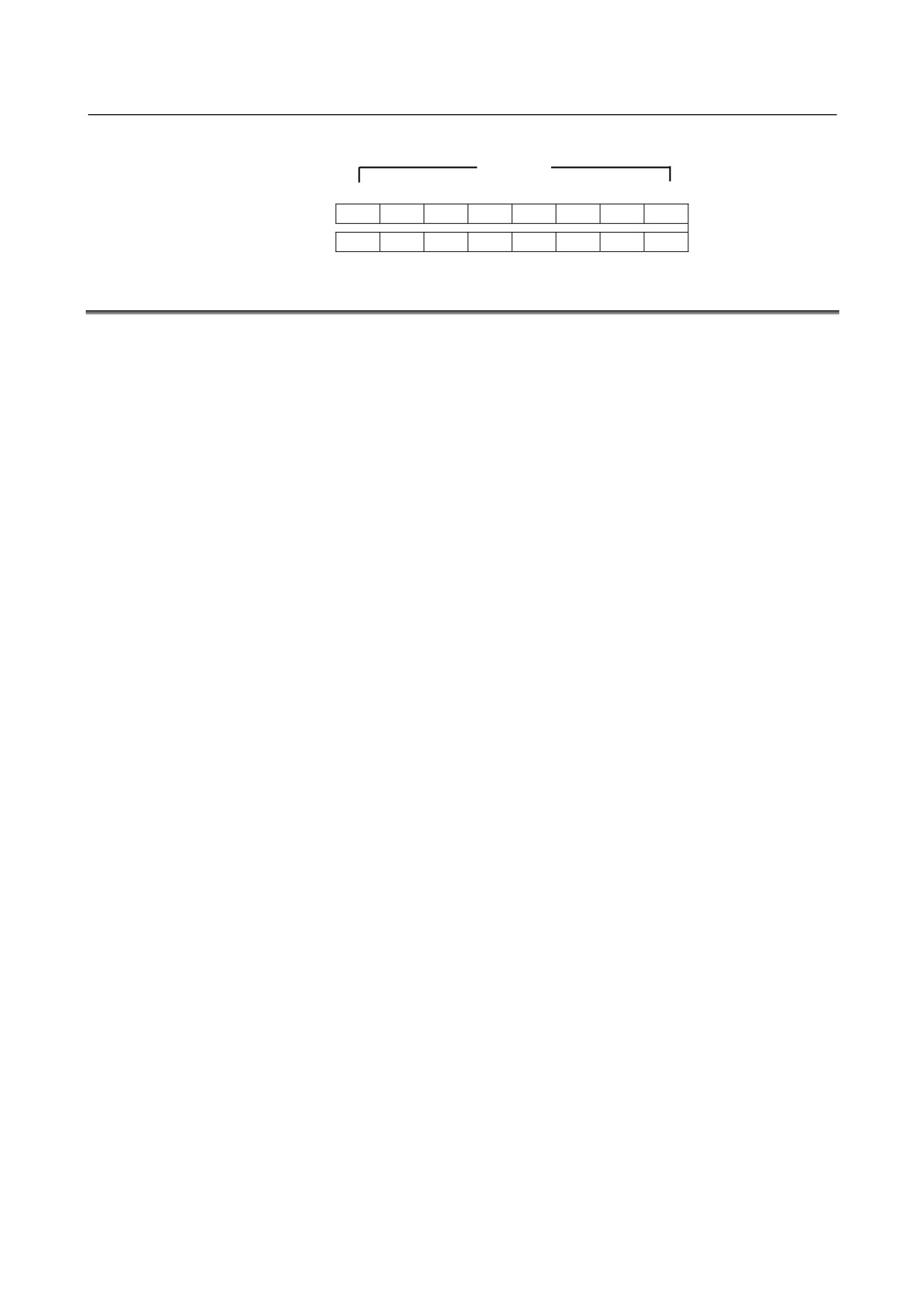
Output section
Output bits
Address in the
7
6
5
4
3
2
1
0
module
Yn
D7
D6
D5
D4
D3
D2
D1
D0
Yn+1
E7
E6
E5
E4
E3
E2
E1
E0
5.3
SPECIFICATION FOR EACH MODULE
Specifications for the module are shown in the following pages.
5.3.1 Input module
AID32A1
5.3.19
Output module
AOD16C
5.3.2 Input module
AID32B1
5.3.20
Output module
AOD16D
5.3.3 Input module
AID32H1
5.3.21
Output module
AOD16DM
5.3.4 Input module
AID16C
5.3.22
Output module
AOD16D2
5.3.5 Input module
AID16K
5.3.23
Output module
AOD16D3
5.3.6 Input module
AID16D
5.3.24
Output module
AOD16DP
5.3.7 Input module
AID16L
5.3.25
Output module
AOD32C1
5.3.8 Input module
AID16DM
5.3.26
Output module
AOD32C2
5.3.9 Input module
AID16LM
5.3.27
Output module
AOD32D1
5.3.10 Input module
AID32E1
5.3.28
Output module
AOD32D2
5.3.11 Input module
AID32E2
5.3.29
Output module
AOA05E
5.3.12 Input module
AID32F1
5.3.30
Output module
AOA08E
5.3.13 Input module
AID32F2
5.3.31
Output module
AOA12F
5.3.14 Input module
AIA16G
5.3.32
Output module
AOR08G
5.3.15 Output module
AOD32A1
5.3.33
Output module
AOR16G
5.3.16 Output module
AOD08C
5.3.34
Output module
AOR16H2
5.3.17 Output module
AOD08D
5.3.35
Input/output module
AIO40A
5.3.18 Output module
AOD08DP
- 35 -
5. DIGITAL INPUT/OUTPUT
MODULES
CONNECTION
B-61813E/06
5.3.1
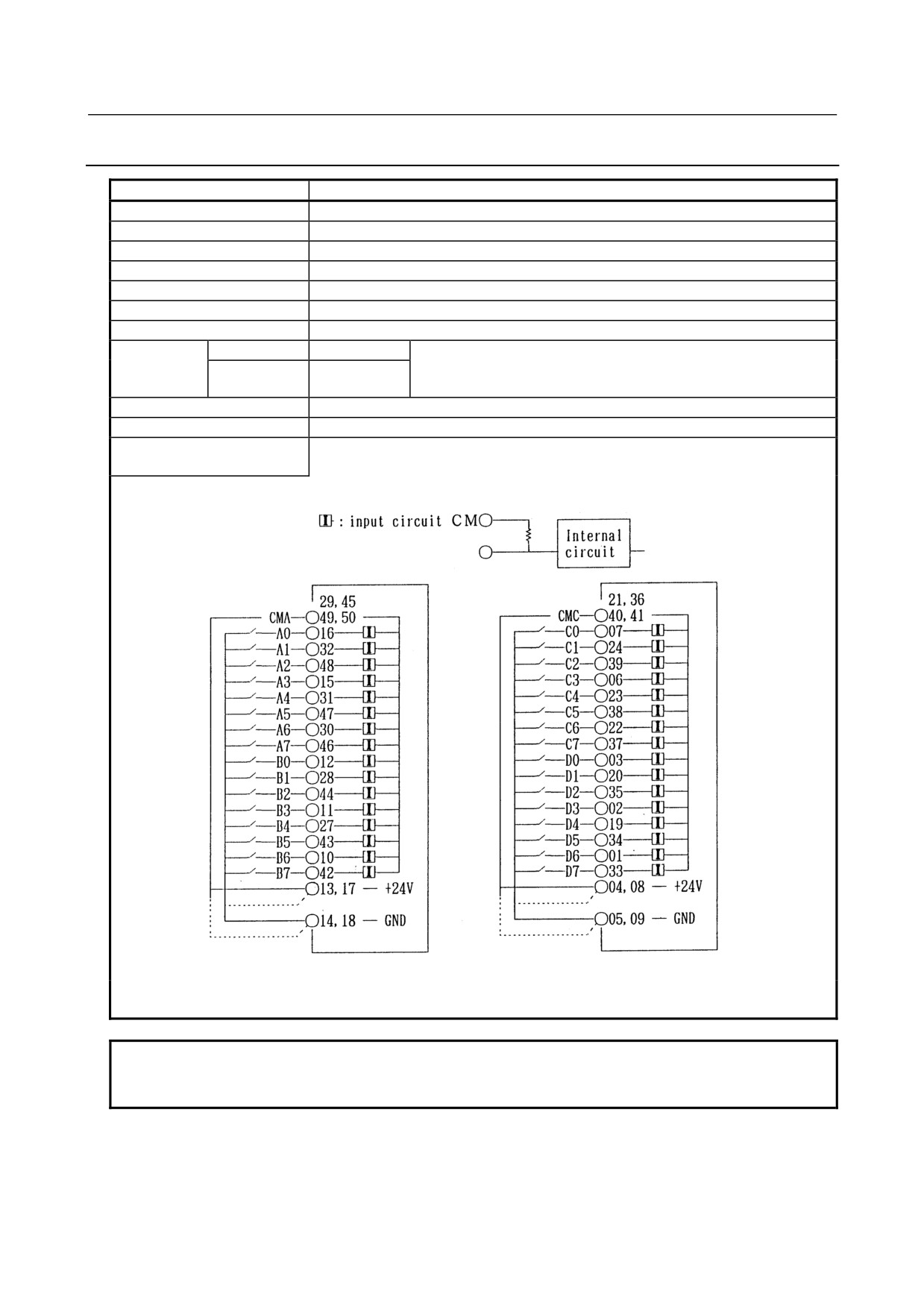
AID32A1 (Non-insulation Type) - Input Module
Item
Specifications
Points/module
32 points
Points/common
16 points/common
Sink/source current
Both directions
Input voltage
24VDC +10%, −20%
Input current
7.5mA (average)
ON voltage, current
Min. 18VDC, min. 6mA
OFF voltage, current
Max. 6VDC, max. 1.5mA
Response time
OFF→ON
Max.20ms
This is the value from input to output in the module. The actual value
ON→OFF
Max.20ms
is determined by adding it to the scanning time depending on each
system.
Input display
Not provided
External connection
Connector (HONDA TSUSHIN MR-50RMA) (male)
Terminal connection and
circuitry
+24V or GND can be selected for input common as above fig.
NOTE
1 Make sure to connect all common (CMA, CMC) pins.
2 This module outputs +24 V on pins 13, 17, 04, and 08.
- 36 -
5.DIGITAL INPUT/OUTPUT
B-61813E/06
CONNECTION
MODULES
5.3.2
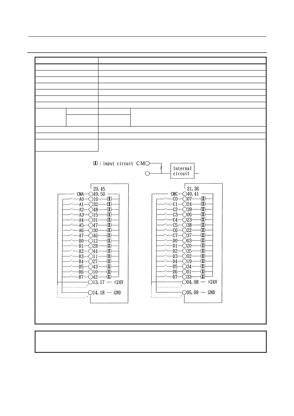
AID32B1 (Non-insulation Type) - Input Module
Item
Specifications
Points/module
32 points
Points/common
16 points/common
Sink/source current
Both directions
Input voltage
24VDC +10%, −20%
Input current
7.5mA (average)
ON voltage, current
Min. 18VDC, min. 6mA
OFF voltage, current
Max. 6VDC, max. 1.5mA
Response time
OFF→ON
Max.2ms
This is the value from input to output in the module. The actual value
ON→OFF
Max.2ms
is determined by adding it to the scanning time depending on each
system.
Input display
Not provided
External connection
Connector (HONDA TSUSHIN MR-50RMA) (male)
Terminal connection and
circuitry
+24V or GND can be selected for input common as above fig.
NOTE
1 Make sure to connect all common (CMA, CMC) pins.
2 This module outputs +24 V on pins 13, 17, 04, and 08.
- 37 -
5. DIGITAL INPUT/OUTPUT
MODULES
CONNECTION
B-61813E/06
5.3.3
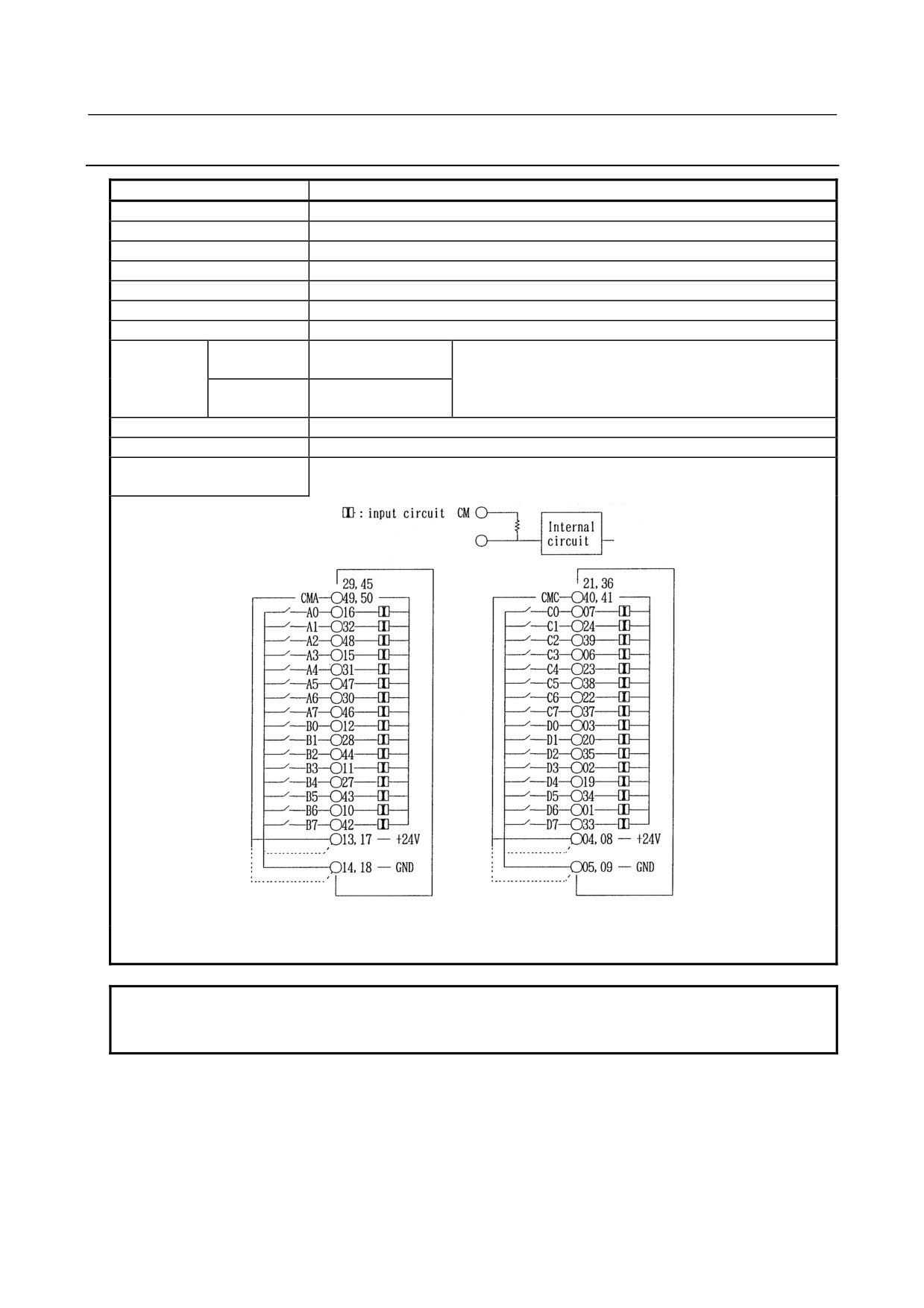
AID32H1 (Non-insulation Type) - Input Module
Item
Specifications
Points/module
32 points
Points/common
16 points/common
Sink/source current
Both directions
Input voltage
24VDC +10%, −20%
Input current
7.5mA (average)
ON voltage, current
Min. 18VDC, min. 6mA
OFF voltage, current
Max. 6VDC, max. 1.5mA
Response time
OFF→ON
Max.2ms (A0 to A7)
This is the value from input to output in the module. The actual
Max.20ms (B0 to D7)
value is determined by adding it to the scanning time
ON→OFF
Max.2ms (A0 to A7)
depending on each system.
Max.20ms (B0 to D7)
Input display
Not provided
External connection
Connector (HONDA TSUSHIN MR-50RMA) (male)
Terminal connection and
circuitry
+24V or GND can be selected for input common as above fig.
NOTE
1 Make sure to connect all common (CMA, CMC) pins.
2 This module outputs +24 V on pins 13, 17, 04, and 08.
- 38 -
5.DIGITAL INPUT/OUTPUT
B-61813E/06
CONNECTION
MODULES
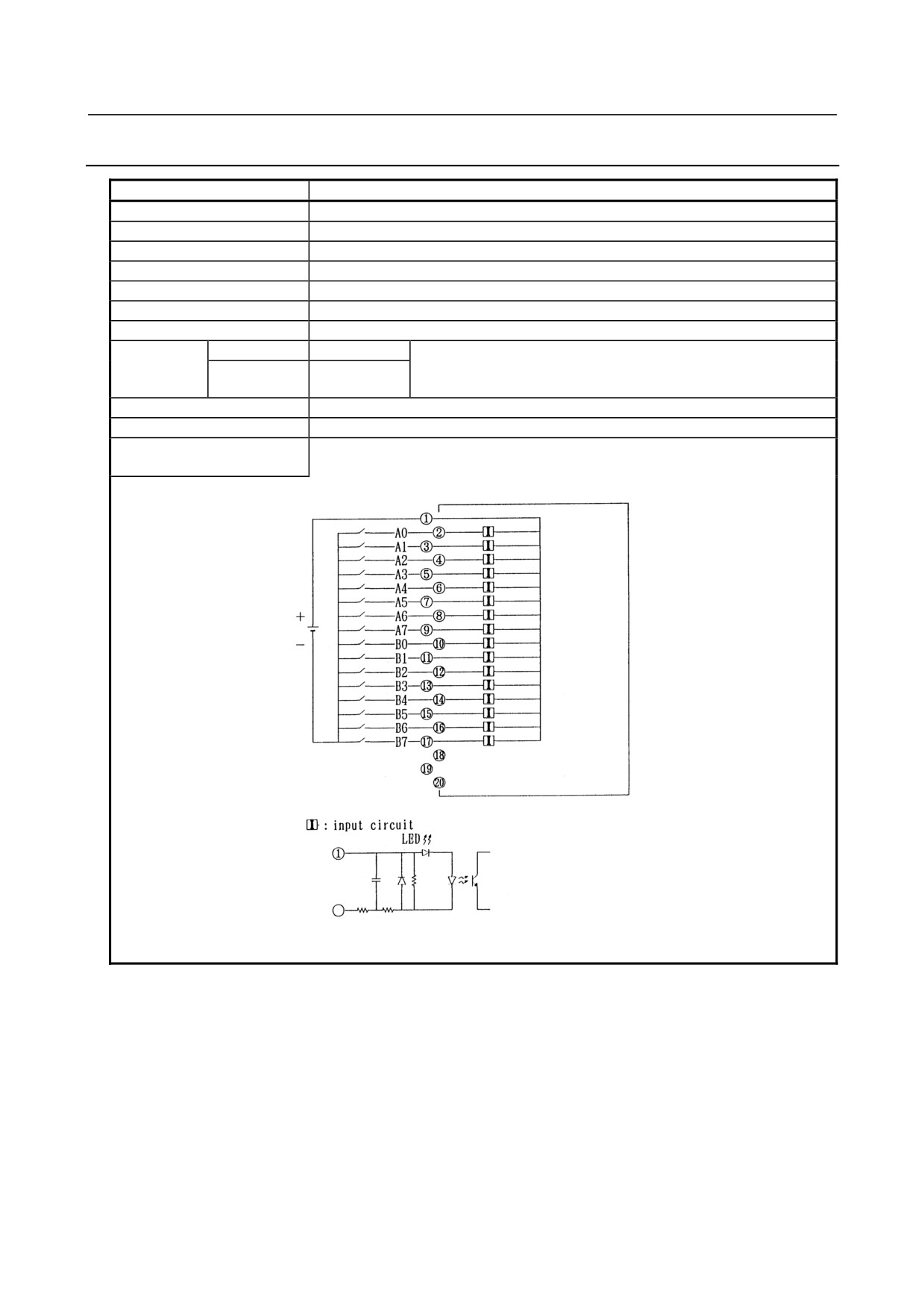
5.3.4
AID16C - Input Module
Item
Specifications
Points/module
16 points
Points/common
16 points/common
Sink/source current
Source current type
Input voltage
24VDC +10%, −20%
Input current
7.5mA (average)
ON voltage, current
Min. 15VDC, min. 4mA
OFF voltage, current
Max. 5VDC, max. 1.5mA
Response time
OFF→ON
Max.20ms
This is the value from input to output in the module. The actual value
ON→OFF
Max.20ms
is determined by adding it to the scanning time depending on each
system.
Input display
LED display
External connection
Terminal block connector (20 terminals, M3.5 screw terminal)
Terminal connection and
circuitry
- 39 -
5. DIGITAL INPUT/OUTPUT
MODULES
CONNECTION
B-61813E/06
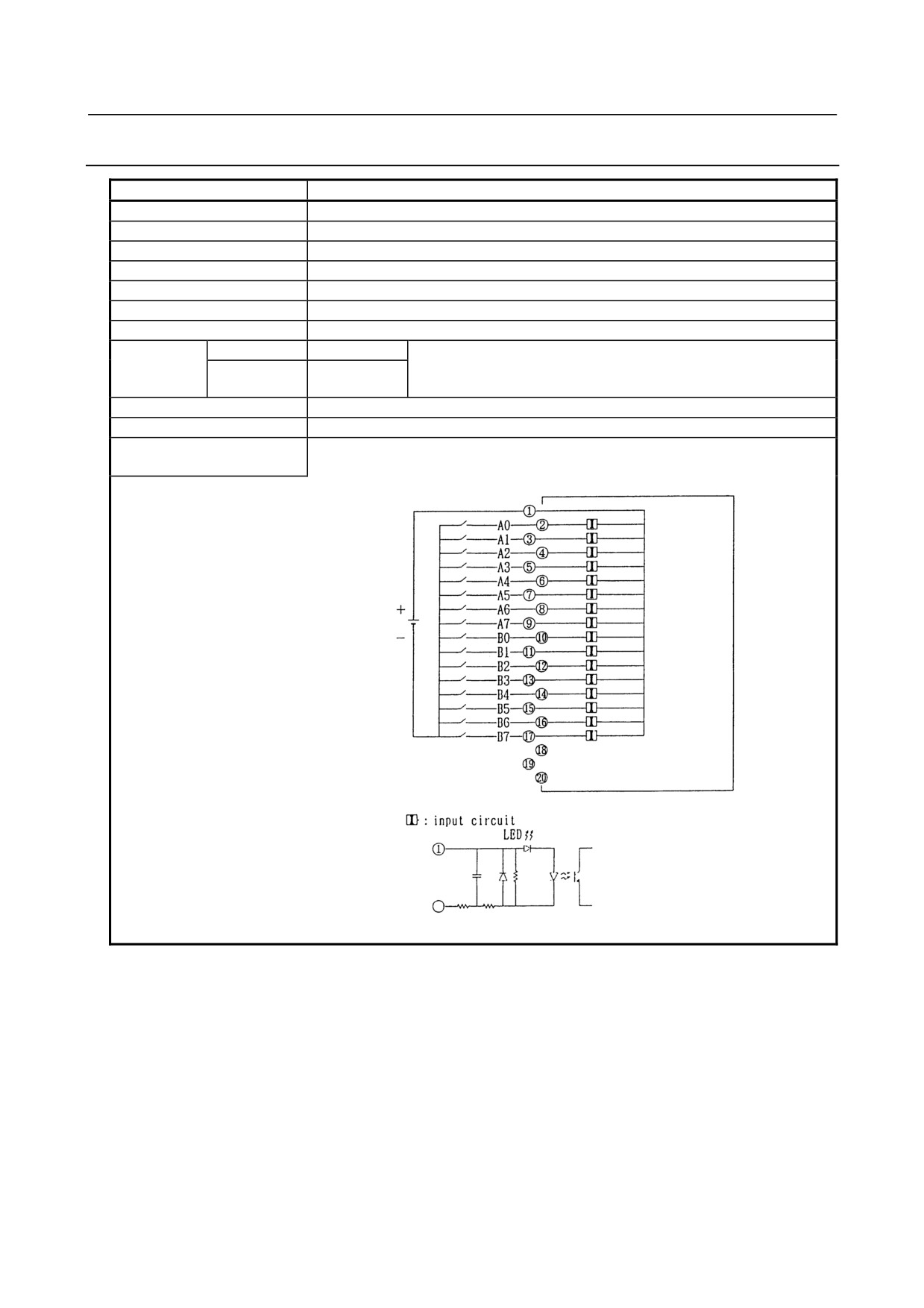
5.3.5
AID16K - Input Module
Item
Specifications
Points/module
16 points
Points/common
16 points/common
Sink/source current
Source current type
Input voltage
24VDC +10%, −20%
Input current
7.5mA (average)
ON voltage, current
Min. 15VDC, min. 4mA
OFF voltage, current
Max. 5VDC, max. 1.5mA
Response
time
OFF→ON
Max.2ms
This is the value from input to output in the module. The actual value
ON→OFF
Max.2ms
is determined by adding it to the scanning time depending on each
system.
Input display
LED display
External connection
Terminal block connector (20 terminals, M3.5 screw terminal)
Terminal connection and
circuitry
- 40 -
5.DIGITAL INPUT/OUTPUT
B-61813E/06
CONNECTION
MODULES
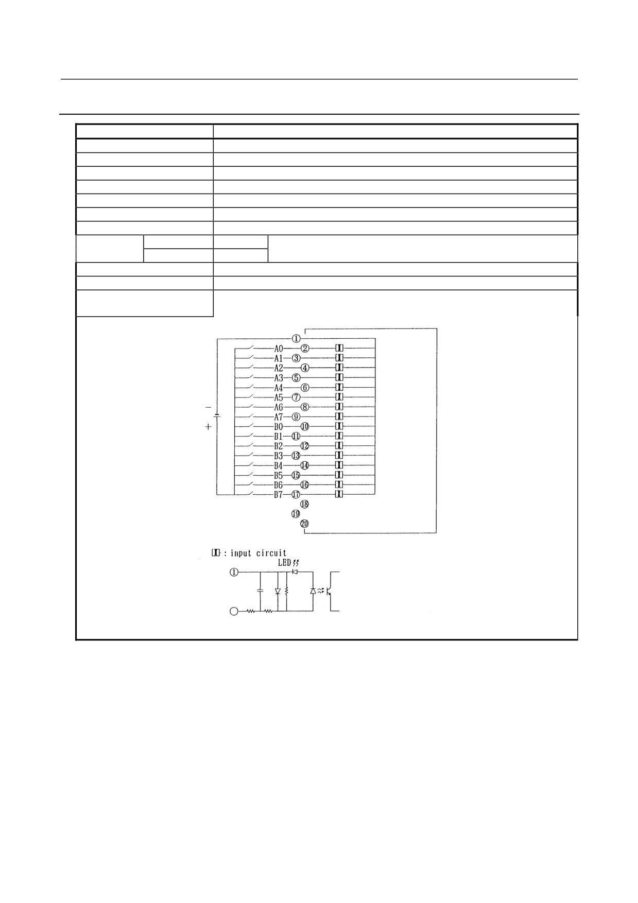
5.3.6
AID16D - Input Module
Item
Specifications
Points/module
16 points
Points/common
16 points/common
Sink/source current
Sink current type
Input voltage
24VDC +10%, −20%
Input current
7.5mA (average)
ON voltage, current
Min. 15VDC, min. 4mA
OFF voltage, current
Max. 5VDC, max. 1.5mA
Response time
OFF→ON
Max.20ms
This is the value from input to output in the module. The actual value is
ON→OFF
Max.20ms
determined by adding it to the scanning time depending on each system.
Input display
LED display
External connection
Terminal block connector (20 terminals, M3.5 screw terminal)
Terminal connection and
circuitry
- 41 -
5. DIGITAL INPUT/OUTPUT
MODULES
CONNECTION
B-61813E/06
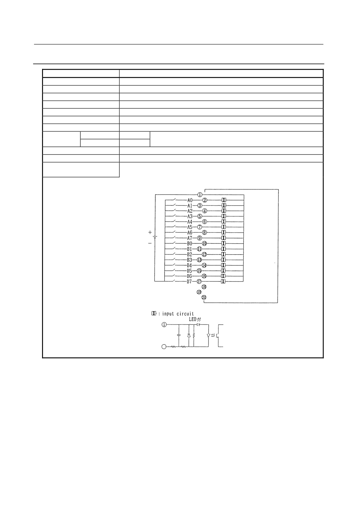
5.3.7
AID16L - Input Module
Item
Specifications
Points/module
16 points
Points/common
16 points/common
Sink/source current
Sink current type
Input voltage
24VDC +10%, −20%
Input current
7.5mA (average)
ON voltage, current
Min. 15VDC, min. 4mA
OFF voltage, current
Max. 5VDC, max. 1.5mA
Response time
OFF→ON
Max.2ms
This is the value from input to output in the module. The actual value is
ON→OFF
Max.2ms
determined by adding it to the scanning time depending on each system.
Input display
LED display
External connection
Terminal block connector (20 terminals, M3.5 screw terminal)
Terminal connection and
circuitry
- 42 -
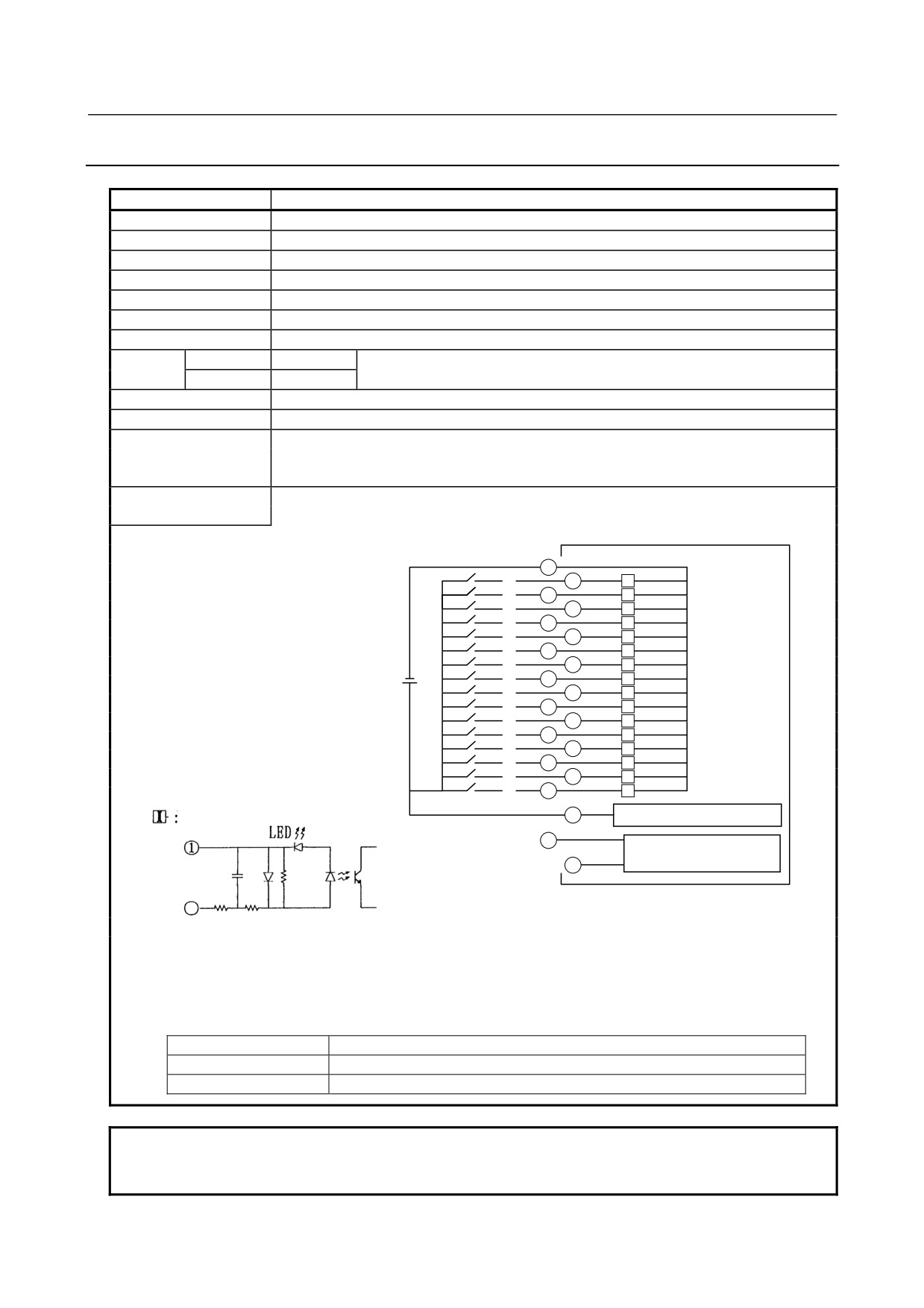
5.DIGITAL INPUT/OUTPUT
B-61813E/06
CONNECTION
MODULES
5.3.8
AID16DM - Input Module
Item
Specifications
Points/module
16 points
Points/common
16 points/common
Sink/source current
Sink current type
Input voltage
24VDC +10%, −20%
Input current
7mA (average)
ON voltage, current
Min. 15VDC, min. 4mA
OFF voltage, current
Max. 5VDC, max. 1.5mA
Response
OFF→ON
Max.20ms
This is the value from input to output in the module. The actual value is
time
ON→OFF
Max.20ms
determined by adding it to the scanning time depending on each system.
Input display
LED display
External connection
Terminal block connector (20 terminals, M3.5 screw terminal)
Number of occupied
I/O Link
Input 3 bytes (including one byte of DI common monitoring information)
input/output points
I/O Link i
Input 2 bytes (DI common monitoring information is transferred to the system
relay area)
Terminal connection and
circuitry
1
A0
2
I
A1
3
I
A2
4
I
A3
5
I
A4
6
I
A5
7
I
A6
8
I
A7
9
I
B0
10
I
B1
11
I
B2
12
I
B3
13
I
B4
14
I
B5
15
I
B6
16
I
B7
17
I
18
Input circuit
Common voltage monitoring
19
AID16L
20
Compatible judging
• Operation modes
With this module, strapping pins <19> and <20> on the terminal board disables the DI common monitoring
function. If you want to use the module in the same manner as for the 16-point DC input module (AID16D) having
no DI common monitoring function, strap pins <19> and <20> on the terminal board.
(19) pin and (20) pin
Operation mode
Open
DI common monitoring function: effective
Short
DI common monitoring function: invalid (equivalent to AID16L)
NOTE
When using the module with the DI common monitoring function enabled, do not
connect anything to pin <19> or <20>.
- 43 -
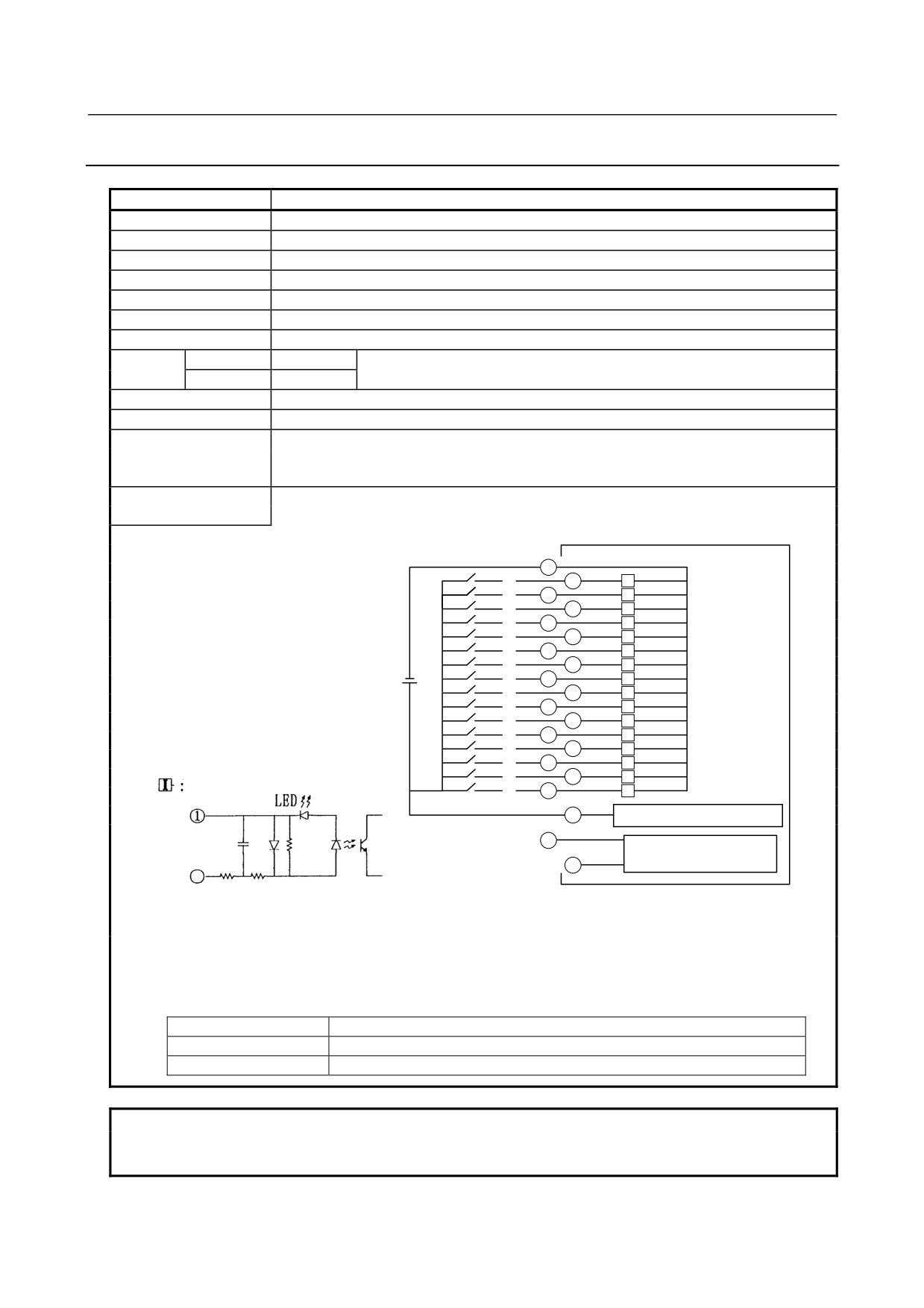
5. DIGITAL INPUT/OUTPUT
MODULES
CONNECTION
B-61813E/06
5.3.9
AID16LM - Input Module
Item
Specifications
Points/module
16 points
Points/common
16 points/common
Sink/source current
Sink current type
Input voltage
24VDC +10%, −20%
Input current
7mA (average)
ON voltage, current
Min. 15VDC, min. 4mA
OFF voltage, current
Max. 5VDC, max. 1.5mA
Response
OFF→ON
Max.2ms
This is the value from input to output in the module. The actual value is
time
ON→OFF
Max.2ms
determined by adding it to the scanning time depending on each system.
Input display
LED display
External connection
Terminal block connector (20 terminals, M3.5 screw terminal)
Number of occupied
I/O Link
Input 3 bytes (including one byte of DI common monitoring information)
input/output points
I/O Link i
Input 2 bytes (DI common monitoring information is transferred to the system
relay area)
Terminal connection and
circuitry
1
A0
2
I
A1
3
I
A2
4
I
A3
5
I
A4
6
I
A5
7
I
A6
8
I
A7
9
I
B0
10
I
B1
11
I
B2
12
I
B3
13
I
B4
14
I
B5
15
I
B6
16
I
Input circuit
B7
17
I
18
Common voltage monitoring
19
AID16L
20
Compatible judging
• Operation modes
With this module, strapping pins <19> and <20> on the terminal board disables the DI common monitoring
function. If you want to use the module in the same manner as for the 16-point DC input module (AID16L) having
no DI common monitoring function, strap pins <19> and <20> on the terminal board.
(19) pin and (20) pin
Operation mode
Open
DI common monitoring function: effective
Short
DI common monitoring function: invalid (equivalent to AID16L)
NOTE
When using the module with the DI common monitoring function enabled, do not
connect anything to pin <19> or <20>.
- 44 -
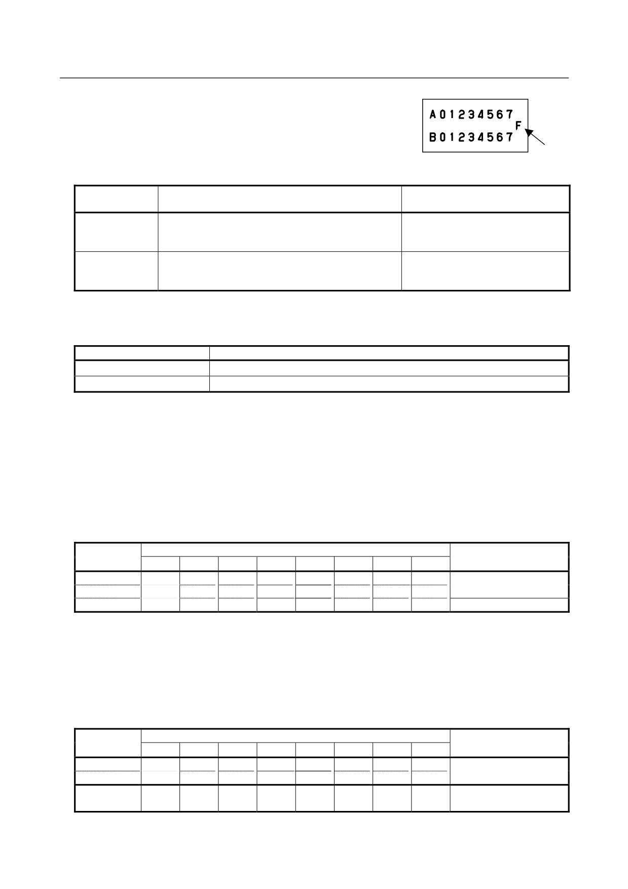
5.DIGITAL INPUT/OUTPUT
B-61813E/06
CONNECTION
MODULES
• DI common monitoring function
Supplying DI common power to pin <18> causes this module to monitor
the common power. The table below lists what is monitored and how the
CNC behaves.
LED
“F”
Surveillance
Contents
LED ”F”
item
Low common
The common voltage is below the minimum input
─
voltage
voltage rating. Alternatively, pin <18> is open or its wire
is broken.
Common voltage
The common voltage became instantaneously lower
Once a voltage moment drop has
moment drop
than the minimum input voltage rating but resumed its
occurred, the LED remains ON until
normal state.
the power to I/O Unit-A is turned OFF.
How the CNC behaves when the DI common monitoring function explained above works varies depending
on the communication method in use, as follows:
Communication method
Behavior of the CNC
I/O Link i
A status alarm is issued.
I/O Link
A specified bit assigned in the DI area becomes 1.
* Refer to the manual of your CNC for descriptions of the status alarm.
• AID16DM/AID16LM allotment and address map
When the DI common monitoring function described above is used with I/O Link, it is necessary to allocate
one byte for DI common alarm information. When it is used with I/O Link i, it is unnecessary because the
DI common alarm information is automatically transferred as status alarms to the system relay area. No DI
common alarm information is transferred to the DI area even if a byte is allocated.
For I/O Link Input: 3 bytes
Bit and terminal name
Address
Data
7
6
5
4
3
2
1
0
Xm
A7
A6
A5
A4
A3
A2
A1
A0
DI data 16 bits
Xm+1
B7
B6
B5
B4
B3
B2
B1
B0
Xm+2
E1
E0
DI common alarm
*=Don’t care
• The DI common monitoring bits have the following meanings.
E0(Bit0): When “1”, it means the DI common voltage is abnormal.
E1(Bit1): When “1”, it means a DI common voltage moment drop occurred.
• Bit 0 (E0) returns to “0” when the common voltage becomes normal.
• Bit 1 (E1) holds “1” since the occurrence of a voltage moment drop until the power is turned OFF.
For I/O Link i Input: 2 bytes
Bit and terminal name
Address
Data
7
6
5
4
3
2
1
0
Xm
A7
A6
A5
A4
A3
A2
A1
A0
DI data 16 bits
Xm+1
B7
B6
B5
B4
B3
B2
B1
B0
System relay
*
*
*
E1
E0
DI common alarm
area
* Refer to the manual of your CNC for descriptions of the status alarm (system relay area).
- 45 -
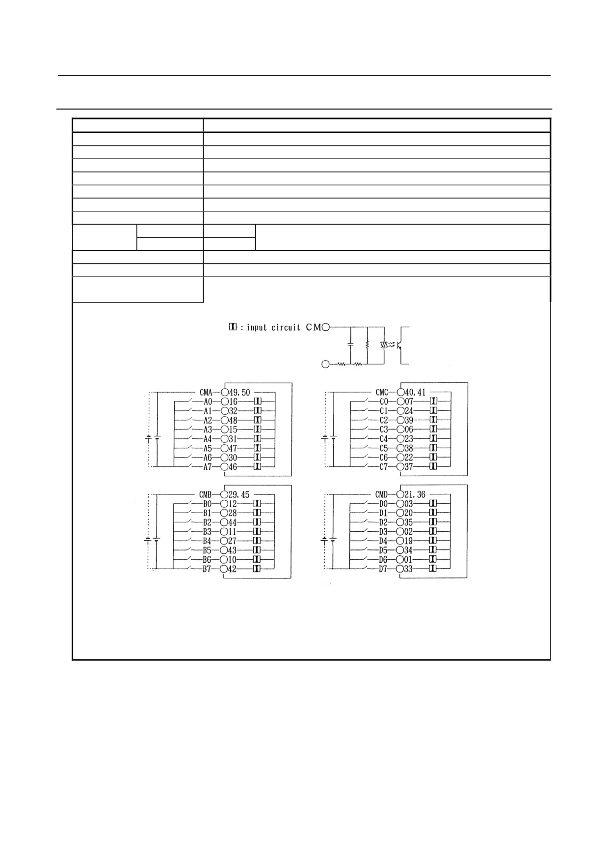
5. DIGITAL INPUT/OUTPUT
MODULES
CONNECTION
B-61813E/06
5.3.10 AID32E1 - Input Module
Item
Specifications
Points/module
32 points
Points/common
8 points/common
Sink/source current
Both directions
Input voltage
24VDC +10%, −20%
Input current
7.5mA (average)
ON voltage, current
Min. 15VDC, min. 4.5mA
OFF voltage, current
Max. 6VDC, max. 2mA
Response time
OFF→ON
Max.20ms
This is the value from input to output in the module. The actual value is
ON→OFF
Max.20ms
determined by adding it to the scanning time depending on each system.
Input display
Not provided
External connection
Connector (HONDA TSUSHIN MR-50RMA) (male)
Terminal connection and
circuitry
- 46 -
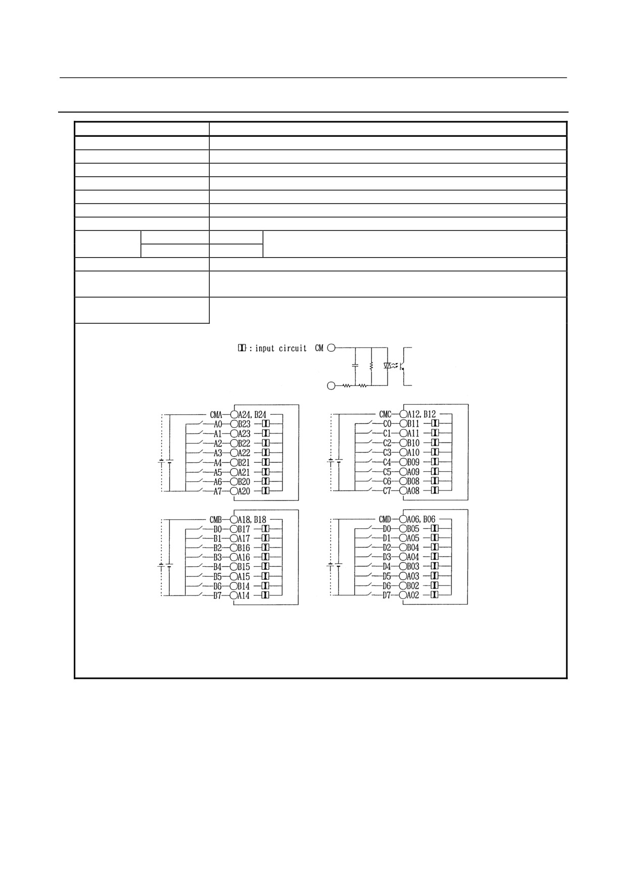
5.DIGITAL INPUT/OUTPUT
B-61813E/06
CONNECTION
MODULES
5.3.11 AID32E2 - Input Module
Item
Specifications
Points/module
32 points
Points/common
8 points/common
Sink/source current
Both directions
Input voltage
24VDC +10%, −20%
Input current
7.5mA (average)
ON voltage, current
Min. 15VDC, min. 4.5mA
OFF voltage, current
Max. 6VDC, max. 2mA
Response time
OFF→ON
Max.20ms
This is the value from input to output in the module. The actual value is
ON→OFF
Max.20ms
determined by adding it to the scanning time depending on each system.
Input display
Not provided
External connection
Connector (HIROSE ELECTRIC HIF3BB-50PA-2.54DS in accordance with MIL
standard)
Terminal connection and
circuitry
- 47 -
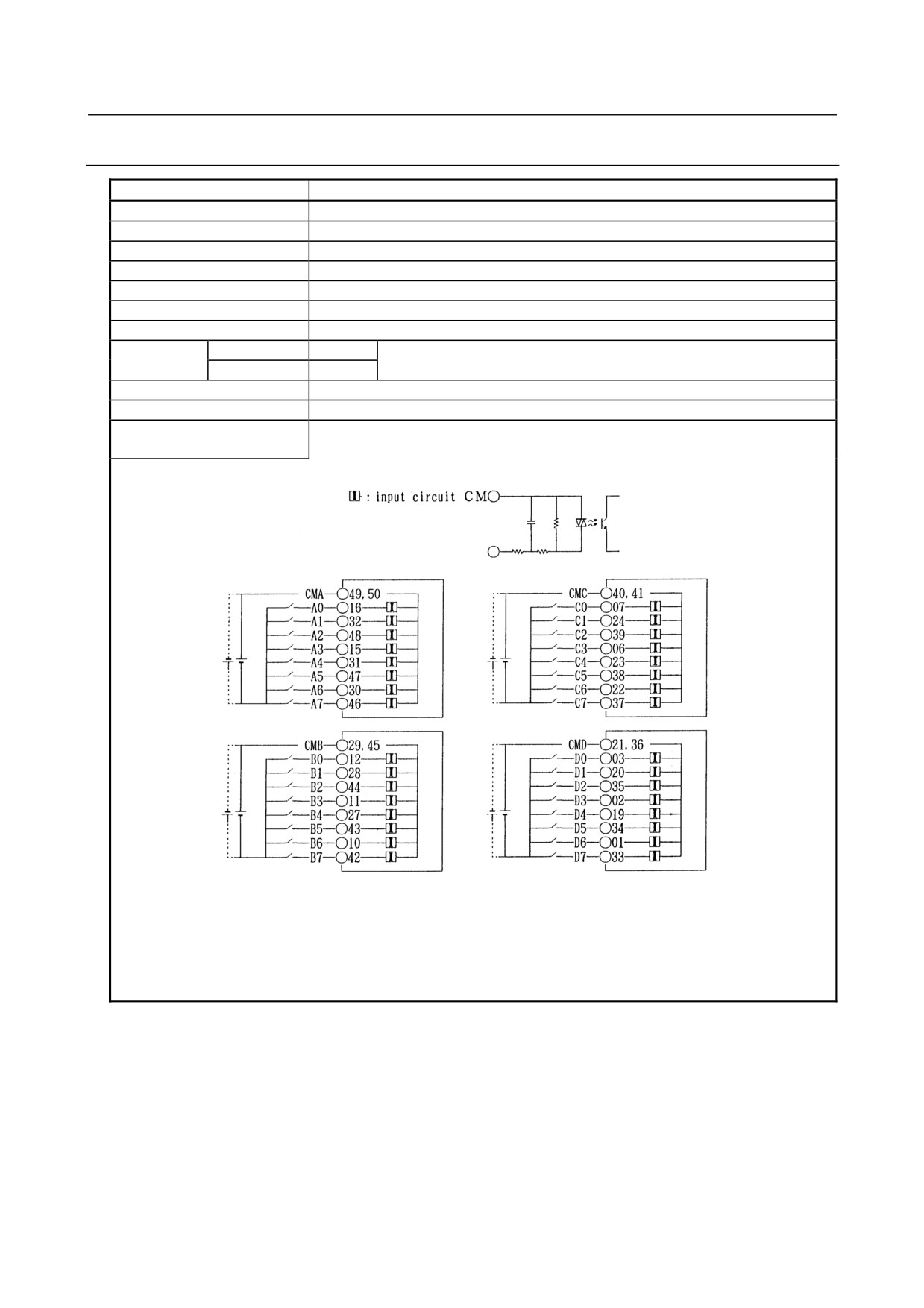
5. DIGITAL INPUT/OUTPUT
MODULES
CONNECTION
B-61813E/06
5.3.12 AID32F1 - Input Module
Item
Specifications
Points/module
32 points
Points/common
8 points/common
Sink/source current
Both directions
Input voltage
24VDC +10%, −20%
Input current
7.5mA (average)
ON voltage, current
Min. 15VDC, min. 4.5mA
OFF voltage, current
Max. 6VDC, max. 2mA
Response time
OFF→ON
Max.2ms
This is the value from input to output in the module. The actual value is
ON→OFF
Max.2ms
determined by adding it to the scanning time depending on each system.
Input display
Not provided
External connection
Connector (HONDA TSUSHIN MR-50RMA) (male)
Terminal connection and
circuitry
- 48 -
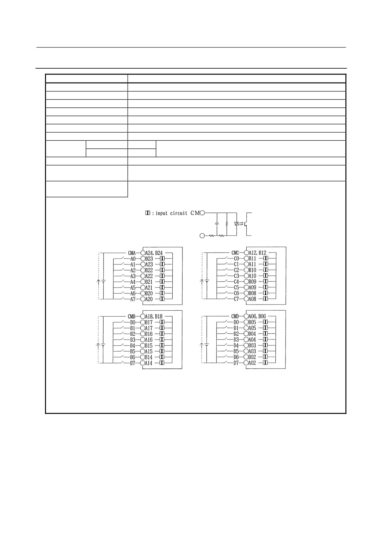
5.DIGITAL INPUT/OUTPUT
B-61813E/06
CONNECTION
MODULES
5.3.13 AID32F2 - Input Module
Item
Specifications
Points/module
32 points
Points/common
8 points/common
Sink/source current
Both directions
Input voltage
24VDC +10%, −20%
Input current
7.5mA (average)
ON voltage, current
Min. 15VDC, min. 4.5mA
OFF voltage, current
Max. 6VDC, max. 2mA
Response time
OFF→ON
Max.2ms
This is the value from input to output in the module. The actual value is
ON→OFF
Max.2ms
determined by adding it to the scanning time depending on each system.
Input display
Not provided
External connection
Connector (HIROSE ELECTRIC HIF3BB-50PA-2.54DS in accordance with MIL
standard)
Terminal connection and
circuitry
- 49 -
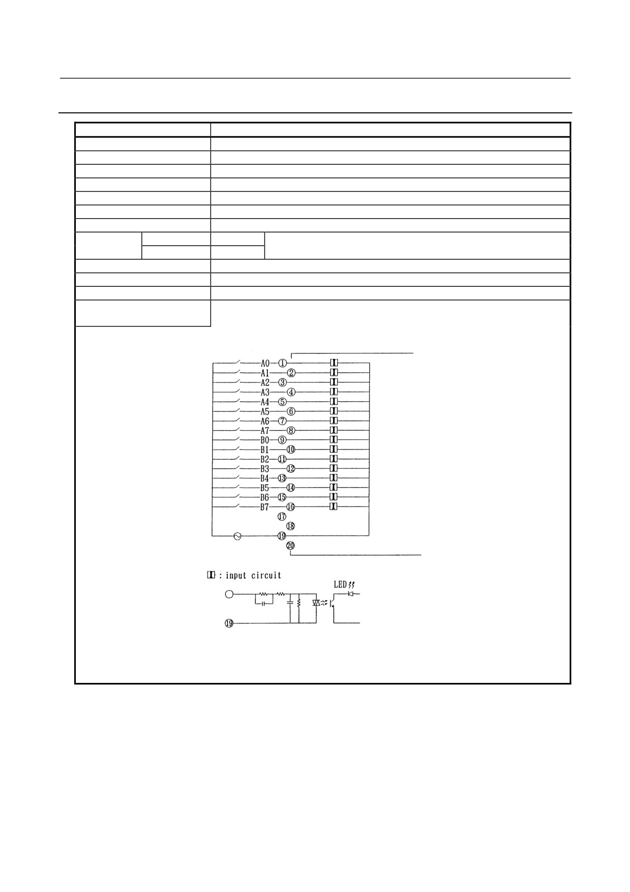
5. DIGITAL INPUT/OUTPUT
MODULES
CONNECTION
B-61813E/06
5.3.14 AIA16G - Input Module
Item
Specifications
Points/module
16 points
Points/common
16 points/common
Sink/source current
100 to 115VAC ±15%
Input voltage
132Vrms, 50/60 Hz
Input current
10.55mArms (115VAC, 50Hz)
ON voltage, current
Min. 74Vrms, min. 6mArms
OFF voltage, current
Max. 20Vrms, max. 2.2mArms
Response time
OFF→ON
Max.35ms
This is the value from input to output in the module. The actual value is
ON→OFF
Max.45ms
determined by adding it to the scanning time depending on each system.
Input display
LED display
External connection
Terminal block connector (20 terminals, M3.5 screw terminal)
Common
16 points/common
Terminal connection and
circuitry
- 50 -
5.DIGITAL INPUT/OUTPUT
B-61813E/06
CONNECTION
MODULES
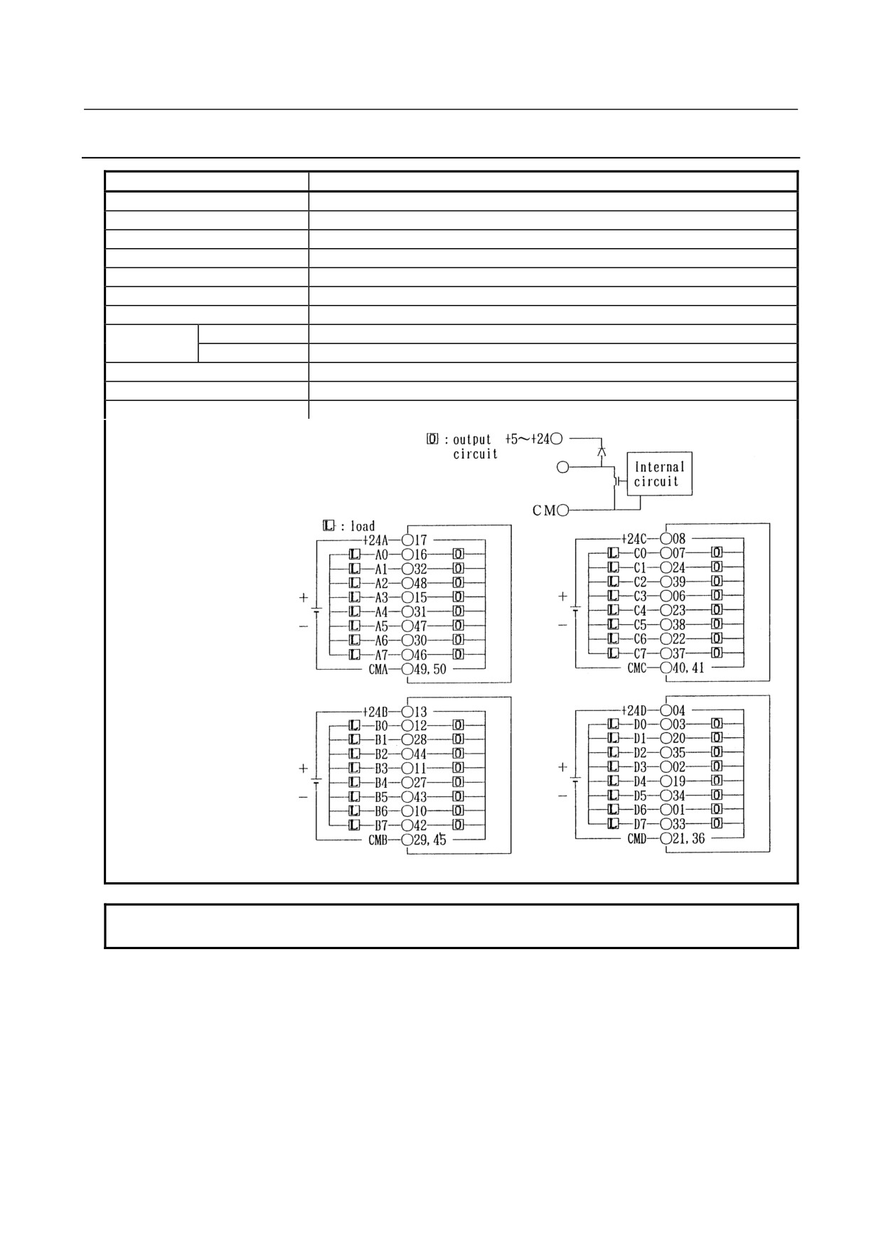
5.3.15 AOD32A1 (Non-insulation Type) - Output Module
Item
Specifications
Points/module
32 points
Points/common
8 points/common
Sink/source current
Sink current type
Rated load voltage
5 to 24VDC +20%, −15%
Maximum load current
0.3A (however 2A/common)
Maximum voltage drop when ON
0.24V (load current ×0.8Ω)
Maximum leak current when OFF
0.1mA
Response time
OFF→ON
Max.1ms
ON→OFF
Max.1ms
Input display
Not provided
External connection
Connector (HONDA TSUSHIN MR-50RMA) (male)
Terminal connection and circuitry
NOTE
For the common (CMA, CMB, CMC, CMD) , make sure to use both of them.
- 51 -
5. DIGITAL INPUT/OUTPUT
MODULES
CONNECTION
B-61813E/06
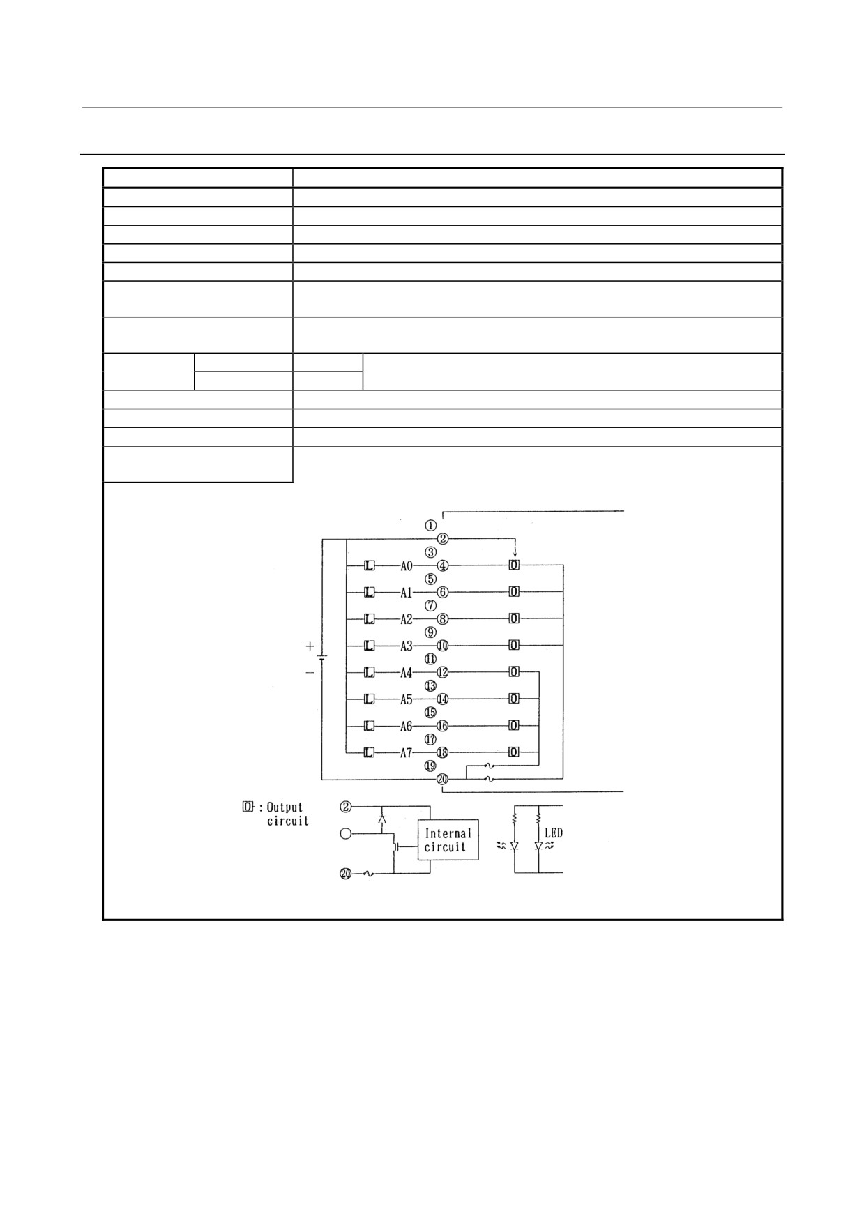
5.3.16 AOD08C - Output Module
Item
Specifications
Points/module
8 points
Points/common
8 points/common
Sink/source current
Sink current type
Rated load voltage
12 to 24VDC +20%, −15%
Maximum load current
2A (however 4A/fuse)
Maximum voltage drop when
0.8V (load current ×0.4Ω)
ON
Maximum leak current when
0.1mA
OFF
Response time
OFF→ON
Max.2ms
This is the value from input to output in the module. The actual value is
ON→OFF
Max.2ms
determined by adding it to the scanning time depending on each system.
Input display
LED display
External connection
Terminal block connector (20 terminals, M3.5 screw terminal)
Fuse
5A, 1 piece for each output A0-A3 and A4-A7.
Terminal connection and
circuitry
- 52 -
5.DIGITAL INPUT/OUTPUT
B-61813E/06
CONNECTION
MODULES
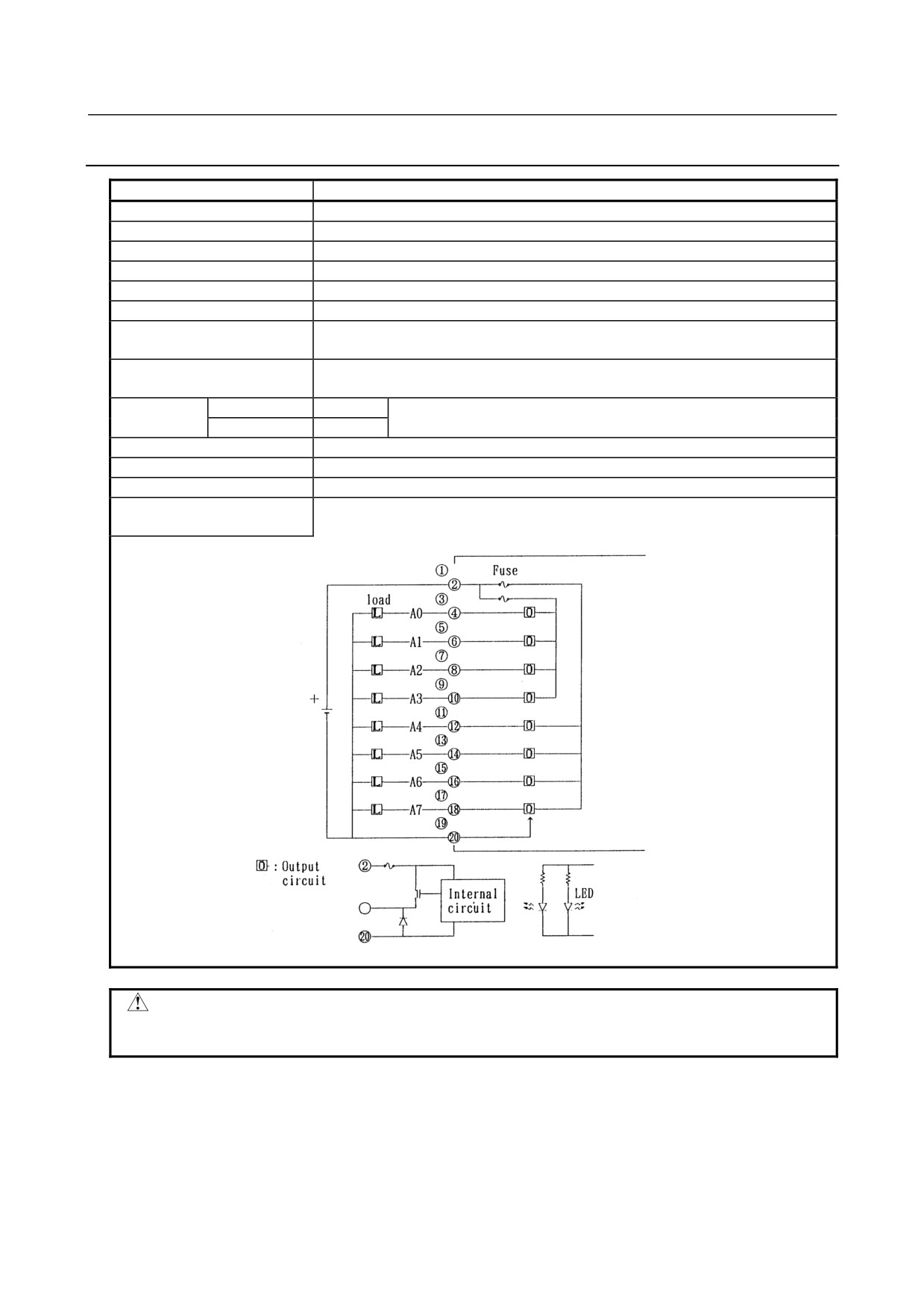
5.3.17 AOD08D - Output Module
Item
Specifications
Points/module
8 points
Points/common
8 points/common
Sink/source current
Source current type
Rated load voltage
12 to 24VDC +20%, −15%
Maximum load current
2A (however 4A/fuse)
Limit of load
Refer to load reduction curve (Fig. 5.3(a))
Maximum voltage drop when
1.2V (load current ×0.6Ω)
ON
Maximum leak current when
0.1mA
OFF
Response
OFF→ON
Max.2ms
This is the value from input to output in the module. The actual value is
Time
ON→OFF
Max.2ms
determined by adding it to the scanning time depending on each system.
Output display
LED display
External connection
Terminal block connector (20 terminals, M3.5 screw terminal)
Fuse
5A, 1 piece for each output A0-A3 and A4-A7.
Terminal connection and
circuitry
CAUTION
Be sure to wire pin <20> as shown above. Keeping the pin open prevents this
module from operating normally, possibly leading to a serious accident.
- 53 -
5. DIGITAL INPUT/OUTPUT
MODULES
CONNECTION
B-61813E/06
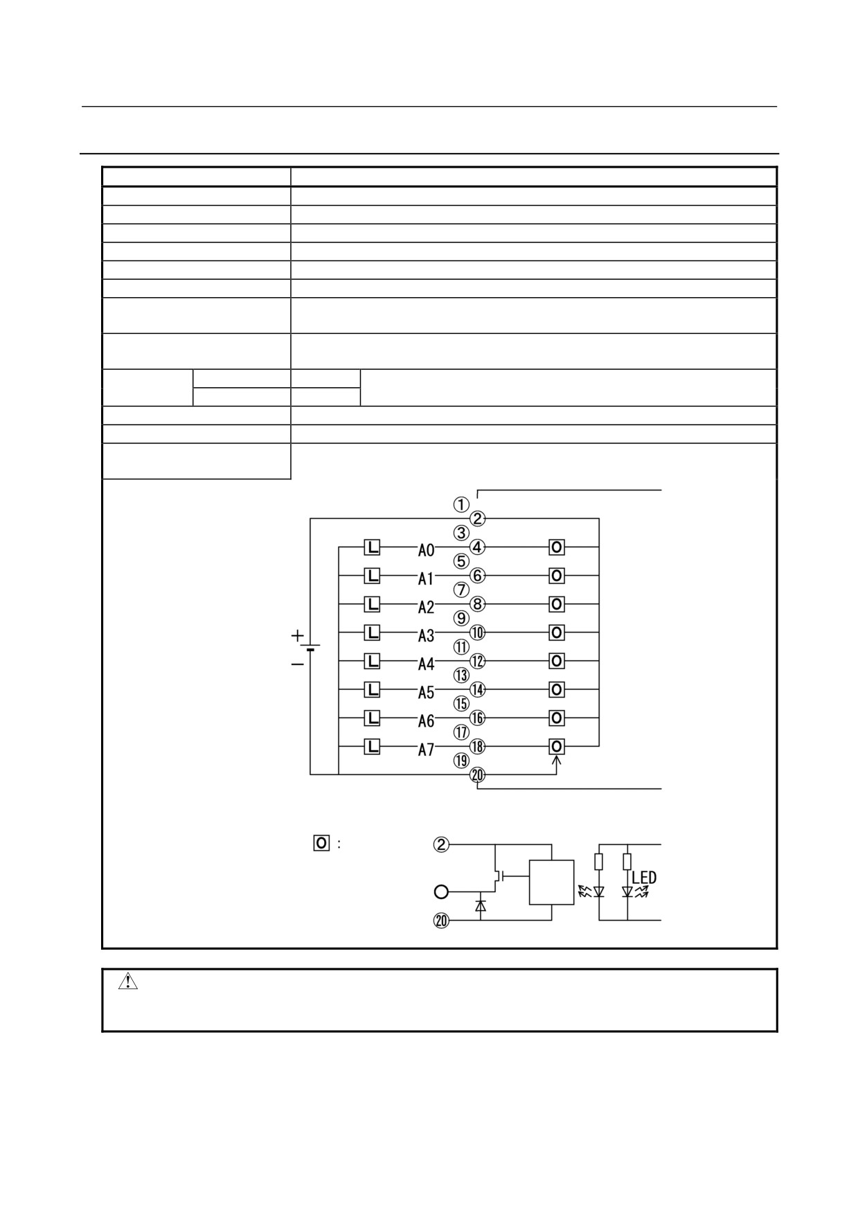
5.3.18 AOD08DP - Output Module
Item
Specifications
Points/module
8 points
Points/common
8 points/common
Sink/source current
Source current type
Rated load voltage
12 to 24VDC +20%, −15%
Maximum load current
2A (however 8A/common)
Output current limit
2.8A (Min.)
Maximum voltage drop when
0.18V (load current ×0.09Ω)
ON
Maximum leak current when
0.1mA
OFF
Response
OFF→ON
Max.2ms
This is the value from input to output in the module. The actual value is
Time
ON→OFF
Max.2ms
determined by adding it to the scanning time depending on each system.
Output display
LED display
External connection
Terminal block connector (20 terminals, M3.5 screw terminal)
Terminal connection and
circuitry
Load
Output
circuit
Internal
circuit
CAUTION
Be sure to wire pin <20> as shown above. Keeping the pin open prevents this
module from operating normally, possibly leading to a serious accident.
- 54 -
5.DIGITAL INPUT/OUTPUT
B-61813E/06
CONNECTION
MODULES
•
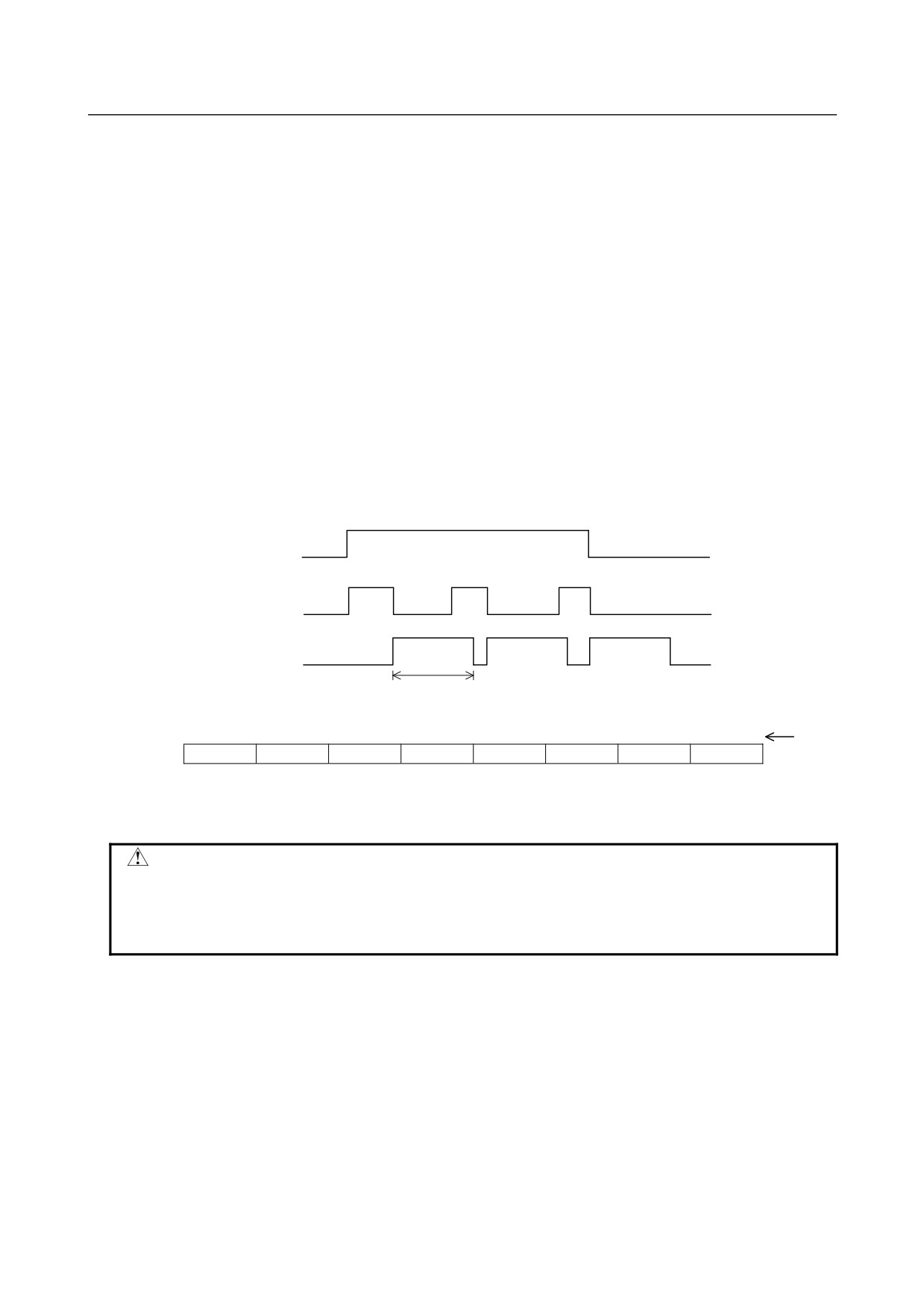
AOD08DP output protection
The internal circuit of this output module can detect a load overcurrent and driver temperature.
To be specific, if the load current increases abnormally, for example, because of a wiring ground
fault, the internal limiter of the driver suppresses the output current. If this condition lasts long,
the driver can get abnormally hot, thus causing the protection circuit to turn off the output. After
the output is turned off and the driver temperature becomes lower, the protection function is
automatically reset to turn on the output; this OFF/ON operations are repeated.
When the overheat protection circuit works to turn off the output, the LED "F" on the front of the
module lights red.
If the protection circuit turns off the output, the output module can detect which DO has
encountered the abnormality, using a DI. This function can be allocated to any DI address (1
byte). If an abnormality is detected, the DI bit corresponding to the DO of interest switches
between "1" and "0". The DI bit stays "1" for at least 10 ms.
If the protection function worked, turn off the power for both the DO and system, and remove the
cause of the overload.
The following timing chart shows how the output and DI behave when the output protection
function works.
DO
Output
DI
10msec or more
Bit
7
6
5
4
3
2
1
0
number
DI(Xm)
A7
A6
A5
A4
A3
A2
A1
A0
The DI bit having the same bit number as the DO (A0 to A7) bit where an abnormality was
detected becomes "1".
CAUTION
An overcurrent prolonged, for example, because of a wiring ground fault may lead
to the break-down of a module. To avoid this failure, build a sequence program
that can turn off the DO corresponding to the bit number of the DI bit which has
been set to "1" because of a failure detected on the driver.
- 55 -
5. DIGITAL INPUT/OUTPUT
MODULES
CONNECTION
B-61813E/06
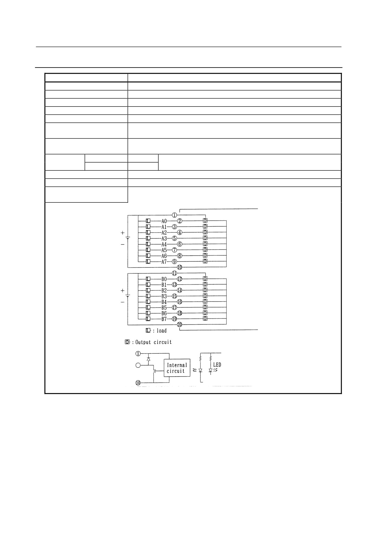
5.3.19 AOD16C - Output Module
Item
Specifications
Points/module
16 points
Points/common
8 points/common
Sink/source current
Sink current type
Rated load voltage
12 to 24VDC +20%, −15%
Maximum load current
0.5A (however 2A/common)
Maximum voltage drop when
0.7V (load current ×1.4Ω)
ON
Maximum leak current when
0.1mA
OFF
Response time
OFF→ON
Max.2ms
This is the value from input to output in the module. The actual value is
ON→OFF
Max.2ms
determined by adding it to the scanning time depending on each system.
Output display
LED display
External connection
Terminal block connector (20 terminals, M3.5 screw terminal)
Terminal connection and
circuitry
- 56 -
5.DIGITAL INPUT/OUTPUT
B-61813E/06
CONNECTION
MODULES
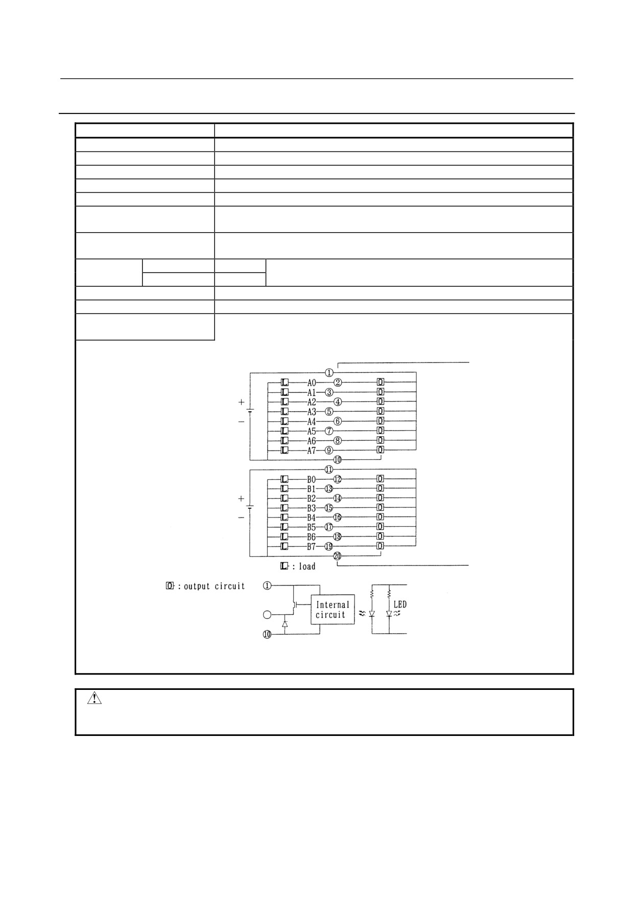
5.3.20 AOD16D - Output Module
Item
Specifications
Points/module
16 points
Points/common
8 points/common
Sink/source current
Source current type
Rated load voltage
12 to 24VDC +20%, −15%
Maximum load current
0.5A (however 2A/common)
Maximum voltage drop when
0.7V (load current ×1.4Ω)
ON
Maximum leak current when
0.1mA
OFF
Response time
OFF→ON
Max.2ms
This is the value from input to output in the module. The actual value is
ON→OFF
Max.2ms
determined by adding it to the scanning time depending on each system.
Output display
LED display
External connection
Terminal block connector (20 terminals, M3.5 screw terminal)
Terminal connection and
circuitry
CAUTION
Be sure to wire pins <10> and <20> as shown above. Keeping the pin open prevents
this module from operating normally, possibly leading to a serious accident.
- 57 -
5. DIGITAL INPUT/OUTPUT
MODULES
CONNECTION
B-61813E/06
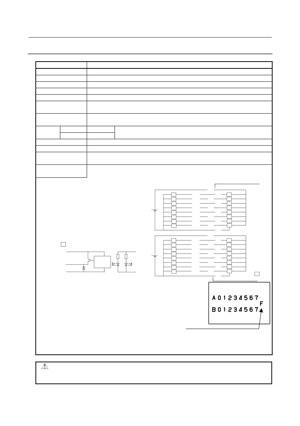
5.3.21 AOD16DM - Output Module
Item
Specifications
Points/module
16 points
Points/common
8 points/common
Sink/source current
Sink current type
Rated load voltage
12 to 24VDC +20%, −15%
Maximum load current
0.5A (however 2A/common)
Maximum voltage drop
0.16V (load current ×0.32Ω)
when ON
Maximum leak current
0.1mA
when OFF
Response
OFF→ON
Max.2ms
This is the value from input to output in the module. The actual value is
time
ON→OFF
Max.2ms
determined by adding it to the scanning time depending on each system.
Output display
LED display
External connection
Terminal block connector (20 terminals, M3.5 screw terminal)
Number of occupied
I/O Link
output 2 bytes, input 3 bytes (the input 3 bytes indicate the abnormal detection information)
input/output points
I/O Link i output 2 bytes (abnormal detection information is transferred to the system relay area)
Terminal connection and
circuitry
①
L
A0
②
O
L
A1
③
O
L
A2
④
O
+
L
A3
⑤
O
L
A4
⑥
O
-
L
A5
⑦
O
L
A6
⑧
O
L
A7
⑨
O
⑩
⑪
L
B0
⑫
O
O
:Output circuit
L
B1
⑬
O
L
B2
⑭
O
①
+
L
B3
⑮
O
L
B4
⑯
O
Output terminal
Internal
LED
-
L
B5
⑰
O
○
circuit
L
B6
⑱
O
L
B7
⑲
O
⑩
L
:Load
⑳
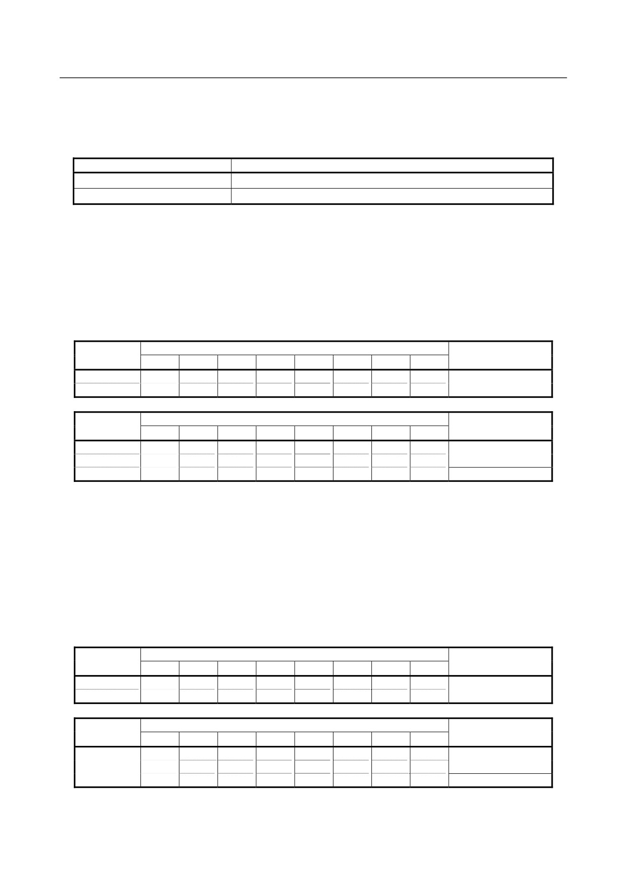
• Abnormal detection functions
The abnormal detection functions of this output module includes output
protection functions, such as overheat, overcurrent, and short-circuit
protection functions, as well as the DO common monitoring function.
Information is sent to the CNC when an abnormal detection function works.
• If an output protection function works, the LED “F” on this module lights.
• The DO common monitoring function works if the DO common voltage
(load voltage) becomes lower than its rating.
• If an abnormal detection function has worked, turn off the power to the DO
and system, and then remove the cause of the alarm.
CAUTION
Be sure to wire pins <10> and <20> as shown above. Keeping the pin open prevents
this module from operating normally, possibly leading to a serious accident.
- 58 -
5.DIGITAL INPUT/OUTPUT
B-61813E/06
CONNECTION
MODULES
• Behavior of the CNC when an abnormal detection function works
How the CNC behaves when the overheat, overcurrent, or short-circuit protection function or the DO
common monitoring function works varies depending on the communication method in use, as follows:
Communication method
Behavior of the CNC
I/O Link i
A status alarm is issued.
I/O Link
A specified bit assigned in the DI area becomes 1.
* Refer to the manual of your CNC for descriptions of the status alarm.
• AOD16DM allotment and address map
When the abnormal detection function described above is used with I/O Link, it is necessary to allocate
input three byte for abnormal detection information. When it is used with I/O Link i, it is unnecessary
because the abnormal detection information is automatically transferred as status alarms to the system relay
area. No abnormal detection information is transferred to the DI area even if a byte is allocated.
For I/O Link Output: 2 bytes, Input: 3 bytes
Bit and terminal name
Address
Data
7
6
5
4
3
2
1
0
Yn
A7
A6
A5
A4
A3
A2
A1
A0
DO data 16 bits
Yn+1
B7
B6
B5
B4
B3
B2
B1
B0
Bit and terminal name
Address
Data
7
6
5
4
3
2
1
0
Xm
A7
A6
A5
A4
A3
A2
A1
A0
DO alarm 16 bits
Xm+1
B7
B6
B5
B4
B3
B2
B1
B0
Xm+2
E1
E0
DO common alarm
*=Don’t care
•
Each DO alarm bit indicates whether the outputs of the respective DO output bits are protected.
“1” corresponds to the protected state.
(Example) Bit 5 (B5) at address Xm+1 represents alarm information for output B5 at address
Yn+1.
Each DO alarm bit returns to “0” when the respective alarm conditions are removed.
•
The DO common alarm bits have the following meanings.
E0 (Bit0) When “1”, it means an abnormal voltage has occurred on the DO (A0 to A7) common.
E1 (Bit1) When “1”, it means an abnormal voltage has occurred on the DO (B0 to B7) common.
EachDO common alarm bit returns to “0” when an abnormal voltage is removed.
For I/O Link i Output: 2 bytes
Bit and terminal name
Address
Data
7
6
5
4
3
2
1
0
Yn
A7
A6
A5
A4
A3
A2
A1
A0
DO data 16 bits
Yn+1
B7
B6
B5
B4
B3
B2
B1
B0
Bit and terminal name
Address
Data
7
6
5
4
3
2
1
0
A7
A6
A5
A4
A3
A2
A1
A0
System relay
DO alarm 16 bits
B7
B6
B5
B4
B3
B2
B1
B0
area
*
*
*
E1
E0
DO common alarm
* Refer to the manual of your CNC for descriptions of the status alarm (system relay area).
- 59 -
5. DIGITAL INPUT/OUTPUT
MODULES
CONNECTION
B-61813E/06
5.3.22 AOD16D2 - Output Module
Item
Specifications
Points/module
16 points
Points/common
4 points/common
Sink/source current
Source current type
Rated load voltage
12 to 24VDC +20%, −15%
Maximum load current
2A (4A/common)
Maximum voltage drop when
0.4V (load current ×0.2Ω)
ON
Maximum leak current when
0.1mA
OFF
Response time
OFF→ON
Max.2ms
This is the value from input to output in the module. The actual value is
ON→OFF
Max.2ms
determined by adding it to the scanning time depending on each system.
Output display
LED display
External connection
Connector (HIROSE ELECTRIC HIF4-40P-3.18DS)
Terminal connection and
circuitry
Load
Output circuit
Output terminal
Internal
circuit
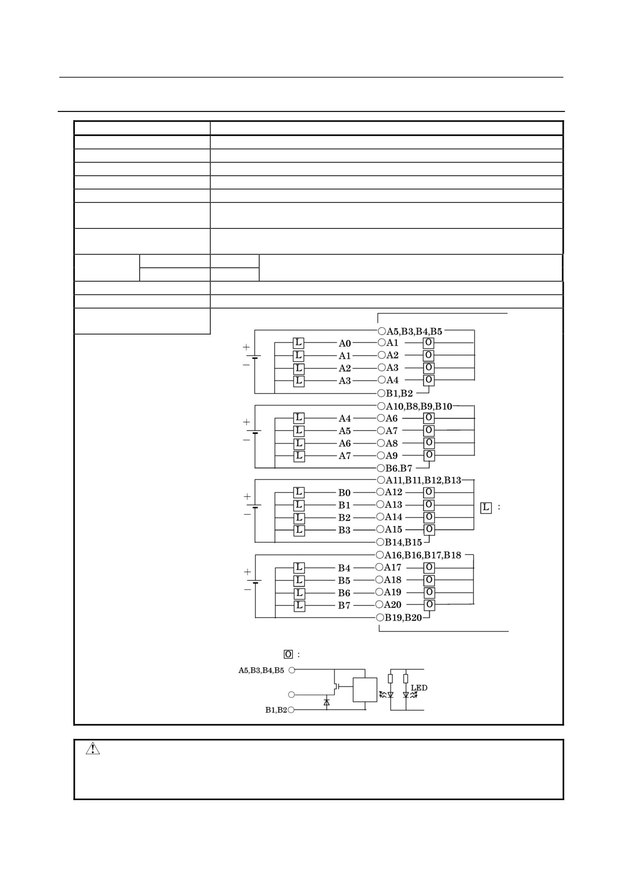
CAUTION
Be sure to wire pins B1, B2, B6, B7, B14, B15, B19, and B20 as shown above.
Keeping the pin open prevents this module from operating normally, possibly
leading to a serious accident.
- 60 -
5.DIGITAL INPUT/OUTPUT
B-61813E/06
CONNECTION
MODULES
5.3.23 AOD16D3 - Output Module
Item
Specifications
Points/module
16 points
Points/common
4 points/common
Sink/source current
Source current type
Rated load voltage
12 to 24VDC +20%, −15%
Maximum load current
2A (4A/common)
Maximum voltage drop when
0.4V (load current ×0.2Ω)
ON
Maximum leak current when
0.1mA
OFF
Response time
OFF→ON
Max.2ms
This is the value from input to output in the module. The actual value is
ON→OFF
Max.2ms
determined by adding it to the scanning time depending on each system.
Output display
LED display
External connection
24-pin terminal block (BL3.5/24/90F) manufactured by Weidmüler
Conformable wire (maximum): 1.5 mm2 (VDE)/AWG 14 (UL/CSA)
Note: The terminal block for the cable comes with this module.
Fuse
One 5A fuse for each of output sets A0 to A3, A4 to A7, B0 to B3, and B4 to B7
MP50 (A60L-0001-0046#5.0) manufactured by Daito.
Ordering information for a 4-fuse set: A03B-0819-K104
Terminal connection and
Fuse
circuitry
Fuse
Fuse
Load
Fuse
Output circuit
Output terminal
Internal
circuit
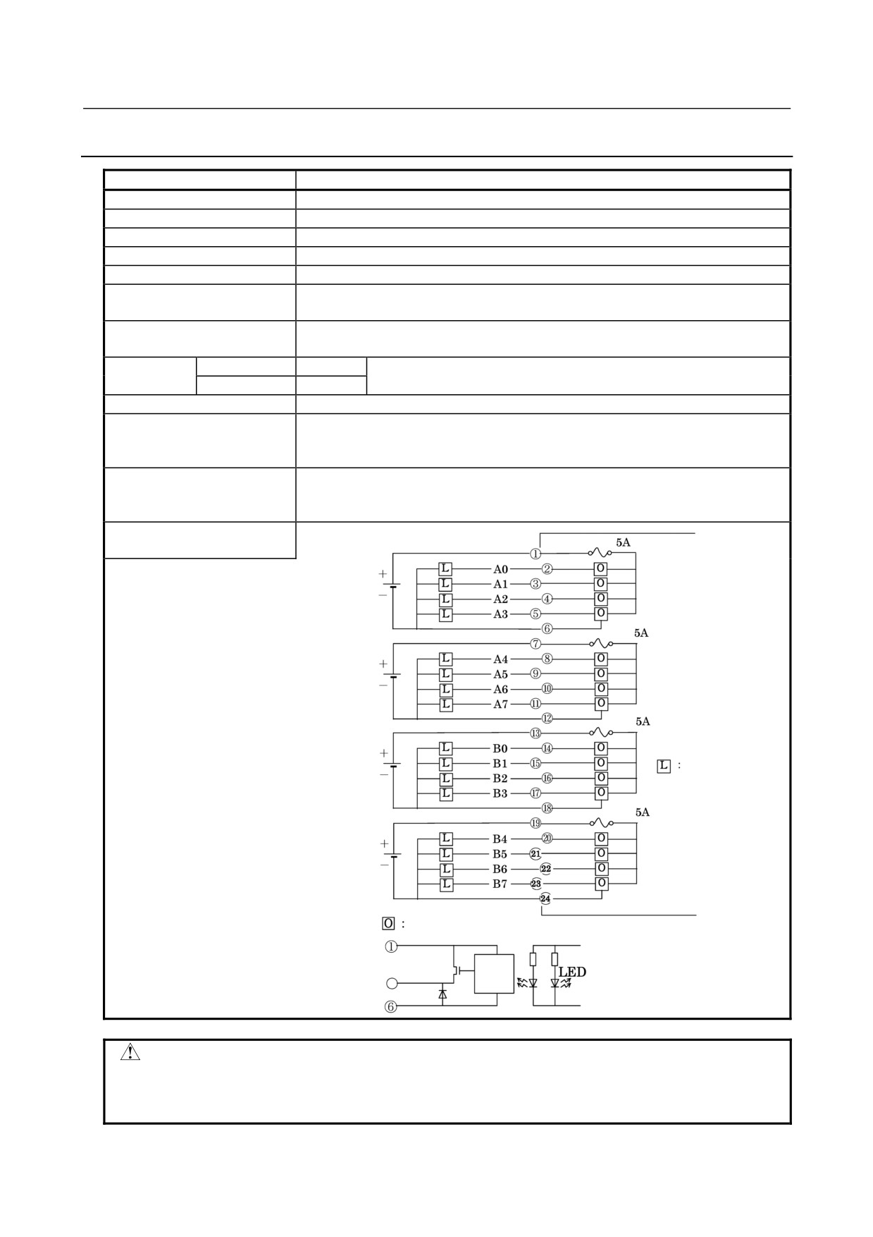
CAUTION
Be sure to wire pins 6, 12, 18, and 24 as shown above. Keeping the pin open
prevents this module from operating normally, possibly leading to a serious
accident.
- 61 -
5. DIGITAL INPUT/OUTPUT
MODULES
CONNECTION
B-61813E/06
5.3.24 AOD16DP - Output Module
Item
Specifications
Points/module
16 points
Points/common
8 points/common
Sink/source current
Source current type
Rated load voltage
12 to 24VDC +20%, −15%
Maximum load current
0.3A (2.4A/common)
0.5A (2A/common)
See the "Load reduction curve" shown in Fig. 5.3 (f).
Maximum voltage drop when
0.63V (load current ×1.25Ω)
ON
Maximum leak current when
40μA
OFF
Response time
OFF→ON
Max.2ms
This is the value from input to output in the module. The actual value is
ON→OFF
Max.2ms
determined by adding it to the scanning time depending on each system.
Output display
LED display
External connection
Connector (20 terminals, M3.5 screw terminal)
Terminal connection and
circuitry
Load
Output circuit
Output terminal
Internal
circuit
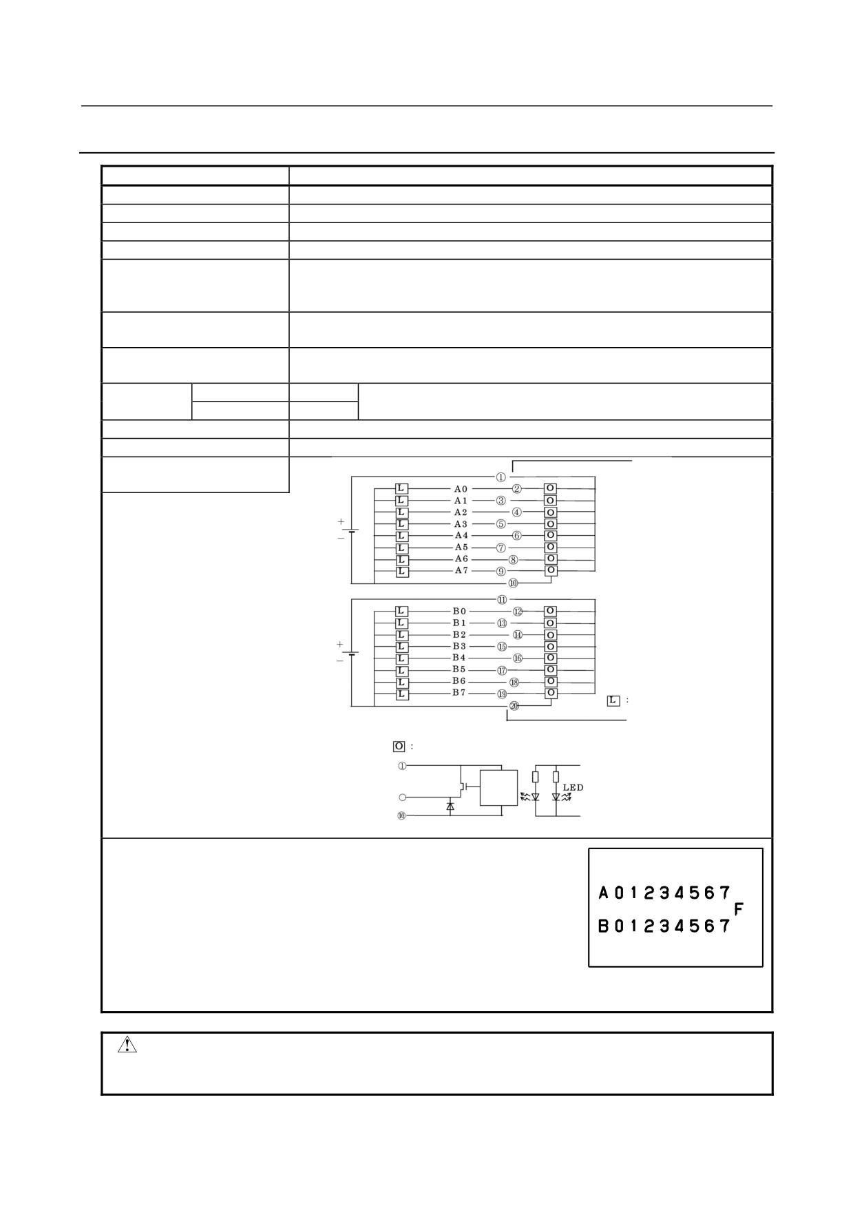
• Output protection
The internal circuit of this output module can detect a load overcurrent.
To be specific, if the load current increases abnormally, for example,
because of a cable ground fault or an internal DO driver is abnormally
heated for some reason, the protection circuit for the DO driver (4-point
unit) works to keep the output of the DO driver turned off until the cause
is removed. When the overheat protection function works, the LED "F"
on the module lights.
If a protection function works, turn off the power to the system, and then remove
the cause of overload.
CAUTION
Be sure to wire pins <10> and <20> as shown above. Keeping the pin open prevents
this module from operating normally, possibly leading to a serious accident.
- 62 -
5.DIGITAL INPUT/OUTPUT
B-61813E/06
CONNECTION
MODULES
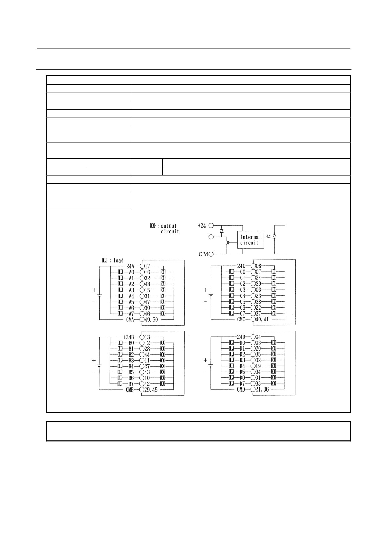
5.3.25 AOD32C1 - Output Module
Item
Specifications
Points/module
32 points
Points/common
8 points/common
Sink/source current
Sink current type
Rated load voltage
12 to 24VDC +20%, −15%
Maximum load current
0.3A (however 2A/common)
Maximum voltage drop when
0.24V (load current ×0.8Ω)
ON
Maximum leak current when
0.1mA
OFF
Response time
OFF→ON
Max.2ms
This is the value from input to output in the module. The actual value is
ON→OFF
Max.2ms
determined by adding it to the scanning time depending on each system.
Output display
Not provided
External connection
Connector (HONDA TSUSHIN MR-50RMA) (male)
Terminal connection and
circuitry
NOTE
For the common (CMA, CMB, CMC, CMD), make sure to use both of them.
- 63 -
5. DIGITAL INPUT/OUTPUT
MODULES
CONNECTION
B-61813E/06
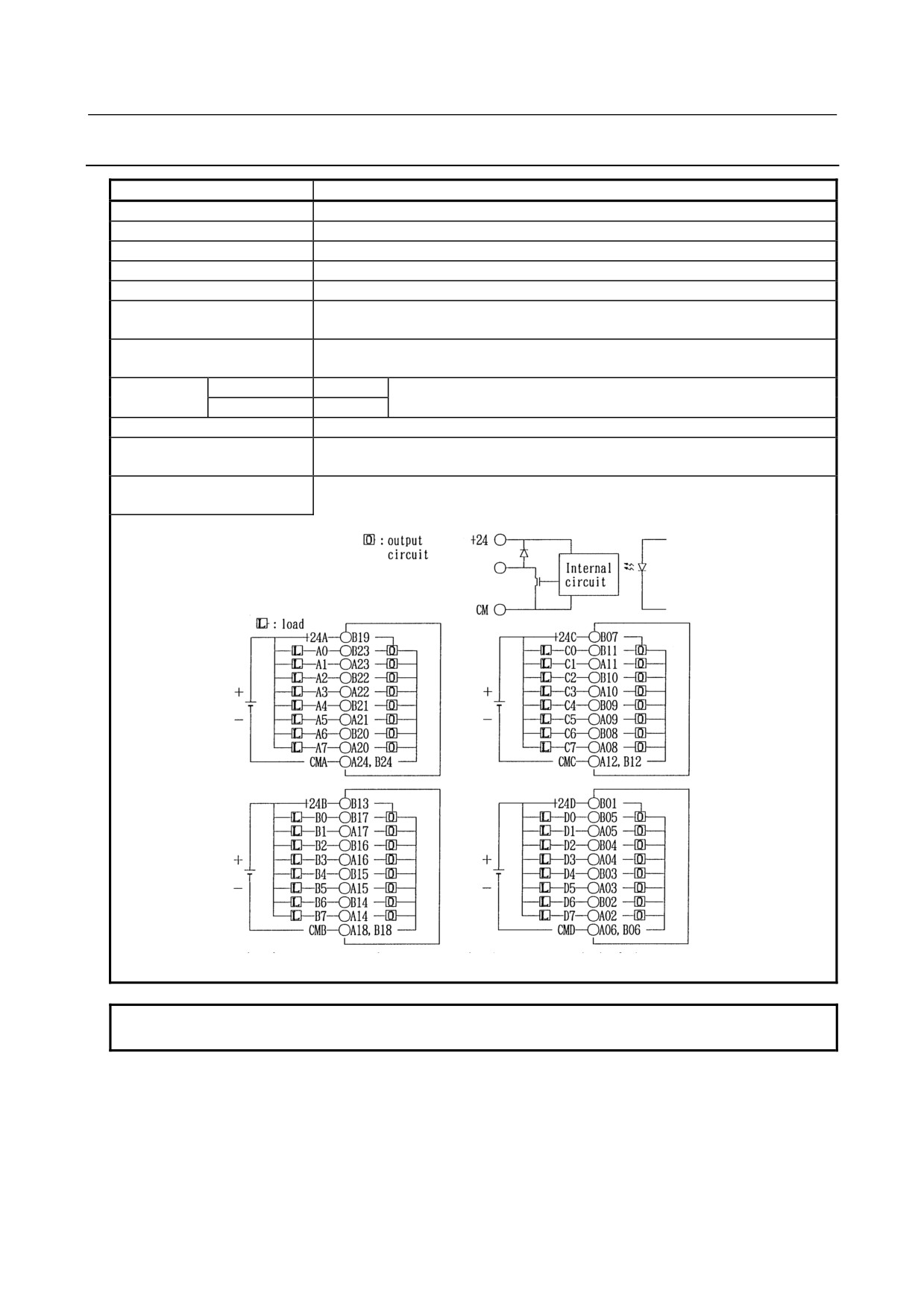
5.3.26 AOD32C2 - Output Module
Item
Specifications
Points/module
32 points
Points/common
8 points/common
Sink/source current
Sink current type
Rated load voltage
12 to 24VDC +20%, −15%
Maximum load current
0.3A (however 2A/common)
Maximum voltage drop when
0.24V (load current ×0.8Ω)
ON
Maximum leak current when
0.1mA
OFF
Response time
OFF→ON
Max.2ms
This is the value from input to output in the module. The actual value is
ON→OFF
Max.2ms
determined by adding it to the scanning time depending on each system.
Output display
Not provided
External connection
Connector (HIROSE ELECTRIC HIF3BB-50PA-2.54DS in accordance with MIL
standard)
Terminal connection and
circuitry
NOTE
For the common (CMA, CMB, CMC, CMD), make sure to use both of them.
- 64 -