FANUC Series 0i-MODEL D, Series 0i Mate-MODEL D. PARAMETER MANUAL - page 1
B-64310EN/02
DEFINITION OF WARNING, CAUTION, AND NOTE
DEFINITION OF WARNING, CAUTION, AND NOTE
This manual includes safety precautions for protecting the user and preventing damage to the machine.
Precautions are classified into Warning and Caution according to their bearing on safety. Also,
supplementary information is described as a Note. Read the Warning, Caution, and Note thoroughly
before attempting to use the machine.
WARNING
Applied when there is a danger of the user being injured or when there is a
danger of both the user being injured and the equipment being damaged if the
approved procedure is not observed.
CAUTION
Applied when there is a danger of the equipment being damaged, if the
approved procedure is not observed.
NOTE
The Note is used to indicate supplementary information other than Warning and
Caution.
• Read this manual carefully, and store it in a safe place.
s-1
B-64310EN/02
PREFACE
PREFACE
Applicable models
This manual describes the following models that are 'Nano CNC'.
'Nano CNC system' which realizes high precision machining can be constructed by combining these
models and high speed, high precision servo controls.
In the text, the abbreviations may be used in addition to Model name indicated below.
Model name
Abbreviation
FANUC Series 0i -TD
0i -TD
Series 0i -D
0i -D
FANUC Series 0i -MD
0i -MD
FANUC Series 0i Mate -TD
0i Mate -TD
Series 0i Mate -D
0i Mate -D
FANUC Series 0i Mate -MD
0i Mate -MD
NOTE
1 For an explanatory purpose, the following descriptions may be used according to
the types of path control used:
- T series: 0i -TD / 0i Mate -TD
- M series: 0i -MD / 0i Mate -MD
2 Some functions described in this manual may not be applied to some products.
For details, refer to the DESCRIPTIONS (B-64302EN).
3 The 0i -D / 0i Mate -D requires setting of parameters to enable part of basic
functions. For the parameters to be set, see Section 4.51, "PARAMETERS OF 0i
-D / 0i Mate -D BASIC FUNCTIONS".
Related manuals of Series 0i -D,Series 0i Mate -D
The following table lists the manuals related to Series 0i -D,Series 0i Mate -D. This manual is indicated
by an asterisk(*).
Table 1 Related manuals
Manual name
Specification number
DESCRIPTIONS
B-64302EN
CONNECTION MANUAL (HARDWARE)
B-64303EN
CONNECTION MANUAL (FUNCTION)
B-64303EN-1
OPERATOR’S MANUAL (Common to Lathe System/Machining Center System)
B-64304EN
OPERATOR’S MANUAL (For Lathe System)
B-64304EN-1
OPERATOR’S MANUAL (For Machining Center System)
B-64304EN-2
MAINTENANCE MANUAL
B-64305EN
PARAMETER MANUAL
B-64310EN
*
START-UP MANUAL
B-64304EN-3
Programming
Macro Compiler / Macro Executor PROGRAMMING MANUAL
B-64303EN-2
Macro Compiler OPERATOR’S MANUAL
B-64304EN-5
C Language PROGRAMMING MANUAL
B-64303EN-3
PMC
PMCPROGRAMMING MANUAL
B-64393EN
Network
PROFIBUS-DP Board CONNECTION MANUAL
B-64403EN
Fast Ethernet / Fast Data Server OPERATOR’S MANUAL
B-64414EN
DeviceNet Board CONNECTION MANUAL
B-64443EN
FL-net Board CONNECTION MANUAL
B-64453EN
p-1
PREFACE
B-64310EN/02
Manual name
Specification number
Dual Check Safety
Dual Check Safety CONNECTION MANUAL
B-64303EN-4
Operation guidance function
MANUAL GUIDE i (Common to Lathe System/Machining Center System)
B-63874EN
OPERATOR’S MANUAL
MANUAL GUIDE i (For Machining Center System) OPERATOR’S MANUAL
B-63874EN-2
MANUAL GUIDE i (Set-up Guidance Functions) OPERATOR’S MANUAL
B-63874EN-1
MANUAL GUIDE 0i OPERATOR’S MANUAL
B-64434EN
TURN MATE i OPERATOR’S MANUAL
B-64254EN
Related manuals of SERVO MOTOR
The following table lists the manuals related to SERVO MOTOR αi/βi series
Table 2 Related manuals
Manual name
Specification number
FANUC AC SERVO MOTOR αi series
B-65262EN
DESCRIPTIONS
FANUC AC SPINDLE MOTOR αi series
B-65272EN
DESCRIPTIONS
FANUC AC SERVO MOTOR βi series
B-65302EN
DESCRIPTIONS
FANUC AC SPINDLE MOTOR βi series
B-65312EN
DESCRIPTIONS
FANUC SERVO AMPLIFIER αi series
B-65282EN
DESCRIPTIONS
FANUC SERVO AMPLIFIER βi series
B-65322EN
DESCRIPTIONS
FANUC SERVO MOTOR αis series
FANUC SERVO MOTOR αi series
FANUC AC SPINDLE MOTOR αi series
B-65285EN
FANUC SERVO AMPLIFIER αi series
MAINTENANCE MANUAL
FANUC SERVO MOTOR βis series
FANUC AC SPINDLE MOTOR βi series
B-65325EN
FANUC SERVO AMPLIFIER βi series
MAINTENANCE MANUAL
FANUC AC SERVO MOTOR αi series
FANUC AC SERVO MOTOR βi series
FANUC LINEAR MOTOR LiS series
B-65270EN
FANUC SYNCHRONOUS BUILT-IN SERVO MOTOR DiS series
PARAMETER MANUAL
FANUC AC SPINDLE MOTOR αi/βi series,
BUILT-IN SPINDLE MOTOR Bi series
B-65280EN
PARAMETER MANUAL
This manual mainly assumes that the FANUC SERVO MOTOR αi series of servo motor is used. For
servo motor and spindle information, refer to the manuals for the servo motor and spindle that are actually
connected.
p-2
B-64310EN/02
TABLE OF CONTENTS
TABLE OF CONTENTS
DEFINITION OF WARNING, CAUTION, AND NOTE
s-1
PREFACE
p-1
1
DISPLAYING PARAMETERS
1
2
SETTING PARAMETERS FROM MDI
2
3
INPUTTING AND OUTPUTTING PARAMETERS THROUGH THE
READER/PUNCHER INTERFACE
4
3.1
OUTPUTTING PARAMETERS THROUGH THE READER/PUNCHER
INTERFACE
4
3.2
INPUTTING PARAMETERS THROUGH THE READER/PUNCHER
INTERFACE
5
3.3
I/O FORMATS
6
3.3.1
Keywords
6
3.3.2
Inch/Metric Switching
7
3.3.3
Bit Format
7
3.3.4
Bit Machine Group Format
7
3.3.5
Bit Path Format
7
3.3.6
Bit Axis Format
8
3.3.7
Bit Spindle Format
8
3.3.8
Byte/Word/Two-Word Format
9
3.3.9
Byte/Word/Two-Word Machine Group Format
9
3.3.10
Byte/Word/Two-Word Path Format
9
3.3.11
Byte/Word/Two-Word Axis Format
10
3.3.12
Byte/Word/Two-Word Spindle Format
10
3.3.13
Real Number Format
10
3.3.14
Real Number Machine Group Format
11
3.3.15
Real Number Path Format
11
3.3.16
Real Number Axis Format
12
3.3.17
Real Number Spindle Format
12
3.3.18
Start and End of a Record
13
4
DESCRIPTION OF PARAMETERS
14
4.1
DATA TYPE
14
4.2
REPRESENTATION OF PARAMETERS
15
4.3
STANDARD PARAMETER SETTING TABLES
16
4.4
PARAMETERS OF SETTING
18
4.5
PARAMETERS OF READER/PUNCHER INTERFACE
20
4.5.1
Parameters Common to All Channels
20
4.5.2
Parameters of Channel 1 (I/O CHANNEL=0)
24
4.5.3
Parameters of Channel 1 (I/O CHANNEL=1)
25
4.5.4
Parameters of Channel 2 (I/O CHANNEL=2)
26
4.6
PARAMETERS OF CNC SCREEN DISPLAY FUNCTIONS
26
4.7
PARAMETERS OF ETHERNET/DATA SERVER FUNCTIONS
27
4.8
PARAMETERS OF POWER MATE CNC
30
4.9
PARAMETERS OF SYSTEM CONFIGURATION
31
c-1
TABLE OF CONTENTS
B-64310EN/02
4.10
PARAMETERS OF AXIS CONTROL/INCREMENT SYSTEM
32
4.11
PARAMETERS OF COORDINATES
43
4.12
PARAMETERS OF STORED STROKE CHECK
49
4.13
PARAMETERS OF THE CHUCK AND TAIL STOCK BARRIER (T SERIES)
.....................................................................................................................53
4.14
PARAMETERS OF FEEDRATE
58
4.15
PARAMETERS OF ACCELERATION/DECELERATION CONTROL
69
4.16
PARAMETERS OF SERVO (1 OF 2)
82
4.17
PARAMETERS OF DI/DO (1 OF 2)
118
4.18
PARAMETERS OF DISPLAY AND EDIT (1 OF 5)
125
4.19
PARAMETERS OF PROGRAMS (1 OF 3)
150
4.20
PARAMETERS OF PITCH ERROR COMPENSATION
159
4.21
PARAMETERS OF SPINDLE CONTROL
165
4.22
PARAMETERS OF TOOL COMPENSATION (1 OF 3)
196
4.23
PARAMETERS OF CANNED CYCLES
208
4.23.1 Parameters of Canned Cycle for Drilling (1 of 2)
208
4.23.2 Parameters of Thread Cutting Cycle (T Series)
214
4.23.3 Parameters of Multiple Repetitive Canned Cycle (T Series)
214
4.23.4 Parameters of Canned Cycle for Drilling (2 of 2)
219
4.23.5 Parameters of Canned Cycle for Grinding (for Grinding Machine)
223
4.24
PARAMETERS OF RIGID TAPPING (1 OF 2)
226
4.25
PARAMETERS OF SCALING (M SERIES) /COORDINATE ROTATION (M
SERIES)
238
4.26
PARAMETERS OF SINGLE DIRECTIONAL POSITIONING (M SERIES) 239
4.27
PARAMETERS OF POLAR COORDINATE INTERPOLATION (T SERIES)
...................................................................................................................240
4.28
PARAMETERS OF NORMAL DIRECTION CONTROL (M SERIES)
241
4.29
PARAMETERS OF INDEX TABLE INDEXING (M SERIES)
242
4.30
PARAMETERS OF SIMPLE STRAIGHTNESS COMPENSATION (M
SERIES)
245
4.31
PARAMETERS OF INCLINATION COMPENSATION
247
4.32
PARAMETERS OF CUSTOM MACROS
248
4.33
PARAMETERS OF PATTERN DATA INPUT
261
4.34
PARAMETERS OF SKIP FUNCTION
262
4.35
PARAMETERS OF EXTERNAL DATA INPUT/OUTPUT
270
4.36
PARAMETERS OF MANUAL HANDLE RETRACE (1 OF 2)
272
4.37
PARAMETERS OF GRAPHIC DISPLAY (1 OF 3)
276
4.38
PARAMETERS OF SCREEN DISPLAY COLORS (1 OF 2)
280
4.39
PARAMETERS OF RUN HOUR AND PARTS COUNT DISPLAY
280
4.40
PARAMETERS OF TOOL LIFE MANAGEMENT (1 OF 2)
283
4.41
PARAMETERS OF POSITION SWITCH FUNCTIONS
290
4.42
PARAMETERS OF MANUAL OPERATION AND AUTOMATIC OPERATION
...................................................................................................................292
4.43
PARAMETERS OF MANUAL HANDLE FEED, HANDLE INTERRUPTION
AND HANDLE FEED IN TOOL AXIAL DIRECTION
292
4.44
PARAMETERS OF REFERENCE POSITION WITH MECHANICAL
STOPPER
296
c-2
B-64310EN/02
TABLE OF CONTENTS
4.45
PARAMETERS OF SOFTWARE OPERATOR'S PANEL
297
4.46
PARAMETERS OF PROGRAM RESTART
300
4.47
PARAMETERS OF POLYGON TURNING (T SERIES)
301
4.48
PARAMETERS OF THE ELECTRONIC GEAR BOX (EGB) (M SERIES) /
GENERAL-PURPOSE RETRACTION
308
4.49
PARAMETERS OF AXIS CONTROL BY PMC (1 OF 2)
314
4.50
PARAMETERS OF 2-PATH CONTROL (T SERIES)
322
4.51
PARAMETERS OF 0i -D / 0i Mate -D BASIC FUNCTIONS
324
4.52
PARAMETERS OF INTERFERENCE CHECK BETWEEN PATHS (T SERIES)
(2-PATH CONTROL)
330
4.53
PARAMETERS OF SYNCHRONOUS/COMPOSITE CONTROL AND
SUPERIMPOSED CONTROL (T SERIES) (1 OF 2)
332
4.54
PARAMETERS OF ANGULAR AXIS CONTROL
344
4.55
PARAMETERS OF AXIS SYNCHRONOUS CONTROL
346
4.56
PARAMETERS OF SEQUENCE NUMBER COMPARISON AND STOP .. 352
4.57
PARAMETERS OF ADVANCED PREVIEW CONTROL / AI ADVANCED
PREVIEW CONTROL / AI CONTOUR CONTROL / AI CONTOUR CONTROL
II (1 OF 2)
352
4.58
OTHER PARAMETERS
355
4.59
PARAMETERS OF MAINTENANCE
359
4.60
PARAMETERS OF THE INCORRECT OPERATION PREVENTION
FUNCTION
361
4.61
PARAMETERS OF AUTOMATIC DATA BACKUP
369
4.62
PARAMETERS OF SCREEN DISPLAY COLORS (2 OF 2)
370
4.63
PARAMETERS OF WAVEFORM DIAGNOSIS
371
4.64
PARAMETERS OF SPINDLE CONTROL WITH SERVO MOTOR (T SERIES)
...................................................................................................................371
4.65
PARAMETERS OF INCH/METRIC CONVERSION AND DIAMETER/RADIUS
SWITCHING (1 OF 2)
377
4.66
PARAMETERS OF DI/DO (2 OF 2)
378
4.67
PARAMETERS OF FEEDRATE CONTROL AND
ACCELERATION/DECELERATION CONTROL
378
4.68
PARAMETERS OF COORDINATE SYSTEM
379
4.69
PARAMETERS OF DISPLAY AND EDIT (2 OF 5)
381
4.70
PARAMETERS OF GRAPHIC DISPLAY (2 OF 3)
387
4.71
PARAMETERS OF DISPLAY AND EDIT (3 OF 5)
392
4.72
PARAMETERS OF TOOL COMPENSATION (2 OF 3)
393
4.73
PARAMETERS OF RIGID TAPPING (2 OF 2)
393
4.74
PARAMETERS OF PROGRAMS (2 OF 3)
397
4.75
PARAMETERS OF DISPLAY AND EDIT (4 OF 5)
397
4.76
PARAMETERS OF PROGRAMS (3 OF 3)
398
4.77
PARAMETERS OF MACHINING QUALITY LEVEL ADJUSTMENT (M
SERIES)
398
4.78
PARAMETERS OF SERVO (2 OF 2)
399
4.79
PARAMETERS OF AXIS CONTROL BY PMC (2 OF 3)
400
4.80
PARAMETERS OF PMC
400
c-3
TABLE OF CONTENTS
B-64310EN/02
4.81
PARAMETERS OF MALFUNCTION PROTECTION
400
4.82
PARAMETERS OF MANUAL HANDLE
401
4.83
PARAMETERS OF SYNCHRONOUS/COMPOSITE CONTROL AND
SUPERIMPOSED CONTROL (T SERIES) (2 OF 2)
402
4.84
PARAMETERS OF AXIS CONTROL BY PMC (3 OF 3)
403
4.85
PARAMETERS OF DISPLAY AND EDIT (5 OF 5)
405
4.86
PARAMETERS OF TOOL LIFE MANAGEMENT (2 OF 2)
412
4.87
PARAMETERS OF THE MACHINING CONDITION SELECTION FUNCTION
...................................................................................................................413
4.88
PARAMETERS OF PARAMETER CHECK SUM
418
4.89
PARAMETERS OF INCH/METRIC CONVERSION AND DIAMETER/RADIUS
SWITCHING (2 OF 2)
419
4.90
PARAMETERS OF LINEAR SCALE WITH ABSOLUTE ADDRESS
REFERENCE POSITION
420
4.91
PARAMETERS OF FSSB
421
4.92
PARAMETERS OF GRAPHIC DISPLAY (3 OF 3)
424
4.93
PARAMETERS OF EMBEDDED ETHERNET
425
4.94
PARAMETERS OF MANUAL HANDLE RETRACE (2 OF 2)
426
4.95
PARAMETERS OF ADVANCED PREVIEW CONTROL / AI ADVANCED
PREVIEW CONTROL / AI CONTOUR CONTROL / AI CONTOUR CONTROL
II (2 OF 2)
427
4.96
PARAMETERS OF NANO SMOOTHING (M SERIES)
429
4.97
PARAMETERS OF TOOL COMPENSATION (3 OF 3)
430
APPENDIX
A CHARACTER CODE LIST
435
c-4
B-64310EN/02
1.DISPLAYING PARAMETERS
1 DISPLAYING PARAMETERS
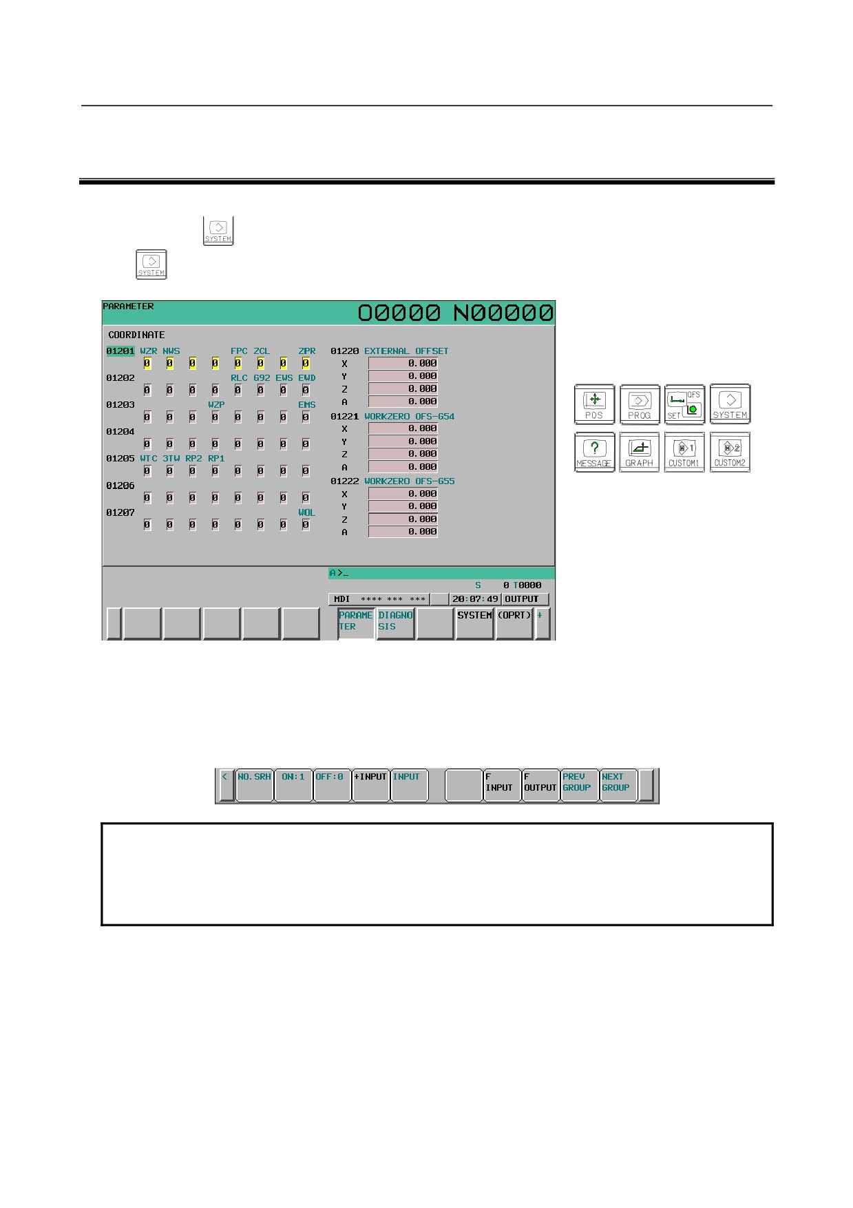
Follow the procedure below to display parameters.
1
Press the
function key on the MDI as many times as required, or alternatively, press the
function key once, then the PARAM section display soft key. The parameter screen is then
selected.
Function keys
2
The parameter screen consists of multiple pages. Use step (a) or (b) to display the page that contains
the parameter you want to display.
(a) Use the page select key or the cursor move keys to display the desired page.
(b) Enter the data number of the parameter you want to display from the keyboard, then press the
[NO.SRH] soft key. The parameter page containing the specified data number appears with the
cursor positioned at the data number. (The data is displayed in reverse video.)
NOTE
If key entry is started with the section select soft keys displayed, they are
replaced automatically by operation select soft keys including [NO.SRH].
Pressing the [(OPRT)] soft key can also cause the operation select keys to be
displayed.
- 1 -
2.SETTING PARAMETERS FROM MDI
B-64310EN/02
2 SETTING PARAMETERS FROM MDI
Follow the procedure below to set parameters.
1
Place the NC in the MDI mode or the emergency stop state.
2
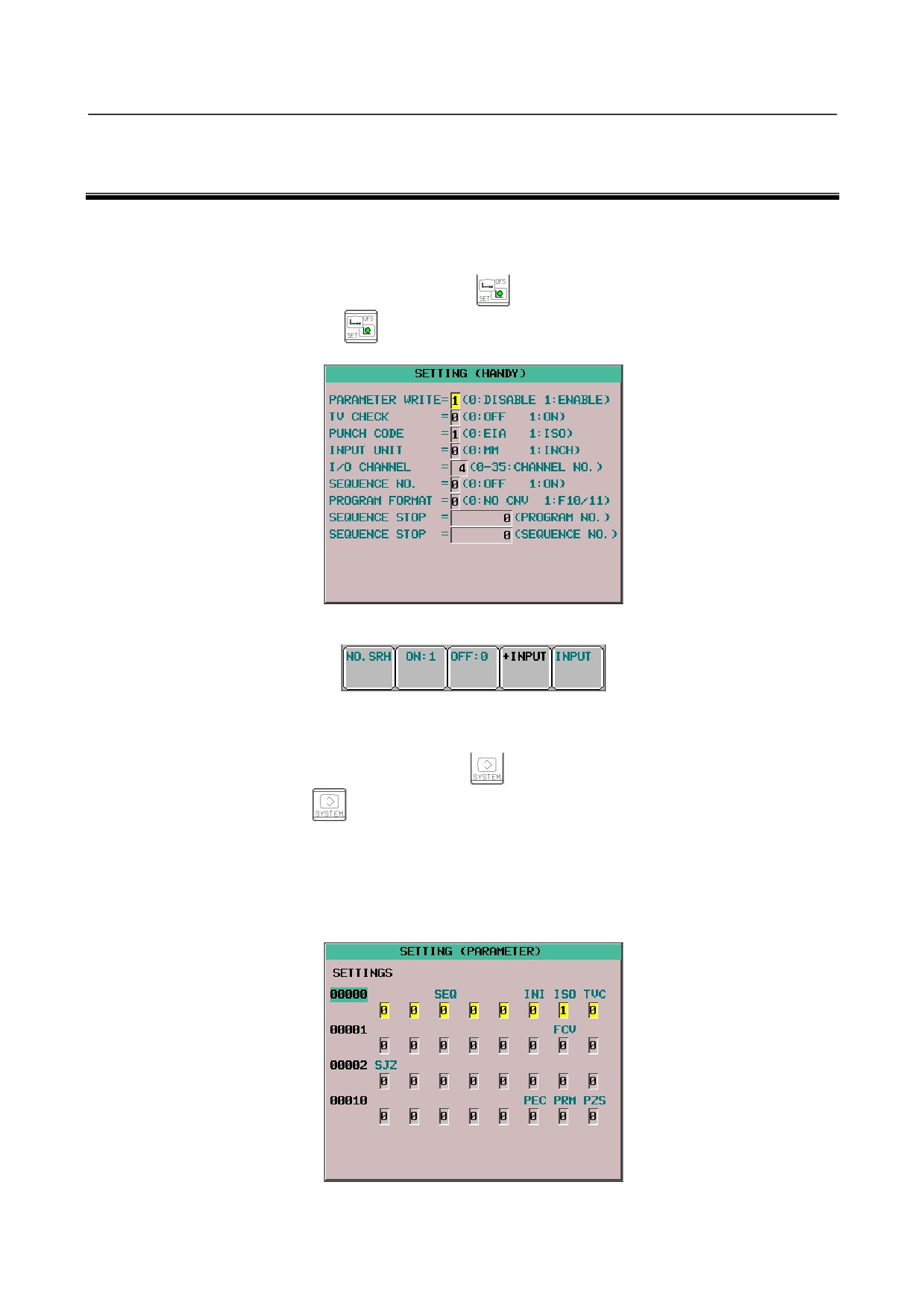
Follow the substeps below to enable writing of parameters.
2-1 To display the setting screen, press the
function key as many times as required, or
alternatively press the
function key once, then the [SETTING] section select soft key.
(The first page of the setting screen appears.)
2-2 Position the cursor on "PARAMETER WRITE" using the cursor move keys.
2-3 Press the [(OPRT)] soft key to display operation select soft keys.
2-4 To set "PARAMETER WRITE=" to 1, press the [ON:1] soft key, or alternatively enter 1 and
press the [INPUT] soft key. From now on, the parameters can be set. At the same time an alarm
condition (SW0100 PARAMETER WRITE ENABLE) occurs in the CNC.
3
To display the parameter screen, press the
function key as many times as required, or
alternatively press the
function key once, then the PARAM section select soft key. (See
Chapter 1, "DISPLAYING PARAMETERS.")
4
Display the page containing the parameter you want to set, and position the cursor on the parameter.
(See Chapter 1, "DISPLAYING PARAMETERS.")
5
Enter data, then press the [INPUT] soft key. The parameter indicated by the cursor is set to the
entered data.
- 2 -
B-64310EN/02
2.SETTING PARAMETERS FROM MDI
Data can be entered continuously for parameters, starting at the selected parameter, by separating
each data item with a semicolon (;).
[Example]
Entering 10;20;30;40 and pressing the INPUT key assigns values 10, 20, 30, and 40 to
parameters in order starting at the parameter indicated by the cursor.
6
Repeat steps (4) and (5) as required.
7
If parameter setting is complete, set "PARAMETER WRITE=" to 0 on the setting screen to disable
further parameter setting.
8
Reset the NC to release the alarm condition (SW0100).
If an alarm condition (PW0000 PLEASE TURN OFF POWER) occurs in the NC, turn it off before
continuing operation.
- 3 -
3. INPUTTING AND OUTPUTTING PARAMETERS
THROUGH THE READER/PUNCHER INTERFACE
B-64310EN/02
3 INPUTTING AND OUTPUTTING
PARAMETERS THROUGH THE
READER/PUNCHER INTERFACE
This section explains the parameter input/output procedures for input/output devices connected to the
reader/puncher interface.
The following description assumes the input/output devices are ready for input/output. It also assumes
parameters peculiar to the input/output devices, such as the baud rate and the number of stop bits, have
been set in advance. (See Section 4.5, “PARAMETERS OF READER/PUNCHER INTERFACE.”)
3.1
OUTPUTTING PARAMETERS THROUGH THE
READER/PUNCHER INTERFACE
1
Select the EDIT mode or set to Emergency stop.
2
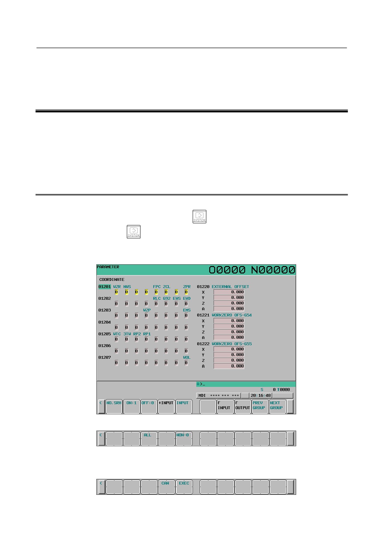
To select the parameter screen, press the
function key as many times as required, or
alternatively press the
function key once, then the PARAM section select soft key.
3
Press the [(OPRT)] soft key to display operation select soft keys, then press the forward menu key
located at the right-hand side of the soft keys to display another set of operation select keys
including [F OUT].
4
Pressing the [F OUT] soft key changes the soft key display as shown below:
5
The [NON-0] soft key selects outputting of the parameters with a non-zero value. The [ALL] soft
key selects outputting of all parameters. When the [NON-0] soft key or [ALL] soft key is pressed,
the soft keys change as described below.
- 4 -
3.INPUTTING AND OUTPUTTING PARAMETERS
B-64310EN/02
THROUGH THE READER/PUNCHER INTERFACE
6
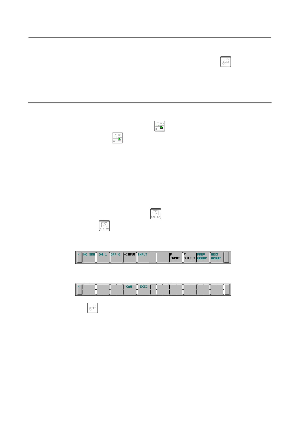
Press the [EXEC] soft key to start parameter output. When parameters are being output, "OUTPUT"
blinks in the state display field on the lower part of the screen.
7
When parameter output terminates, "OUTPUT" stops blinking. Press the
key to interrupt
parameter output.
3.2
INPUTTING PARAMETERS THROUGH THE
READER/PUNCHER INTERFACE
1
Place the NC in the emergency stop state.
2
Enable parameter writing.
2-1 To display the setting screen, press the
function key as many times as required, or
alternatively press the
function key once, then the [SETING] section select soft key.
The first page of the setting screen appears.
2-2 Position the cursor on "PARAMETER WRITE" using the cursor move keys.
2-3 Press the [(OPRT)] soft key to display operation select soft keys.
2-4 To set "PARAMETER WRITE=" to 1, press the [ON:1] soft key, or alternatively enter 1, then
press the [INPUT] soft key. From now on, parameters can be set.
At the same time an alarm condition (SW0100 PARAMETER WRITE ENABLE) occurs in the
NC.
3
To select the parameter screen, press the
function key as many times as required, or
alternatively press the
key once, then [PARAM] soft key.
4
Press the [(OPRT)] soft key to display operation select keys, then press the forward menu key
located at the right-hand side of the soft keys to display another set of operation select soft keys
including [F IN].
5
Pressing the [F IN] soft key changes the soft key display as shown below:
6
Press the [EXEC] soft key to start inputting parameters from the input/output device.
When parameters are being input, "INPUT" blinks in the state display field on the lower part of the
screen. Press the
key to interrupt parameter input.
7
When parameter read terminates, "INPUT" stops blinking, and an alarm condition (PW0100) occurs
in the NC. Turn it off before continuing operation.
- 5 -
3. INPUTTING AND OUTPUTTING PARAMETERS
THROUGH THE READER/PUNCHER INTERFACE
B-64310EN/02
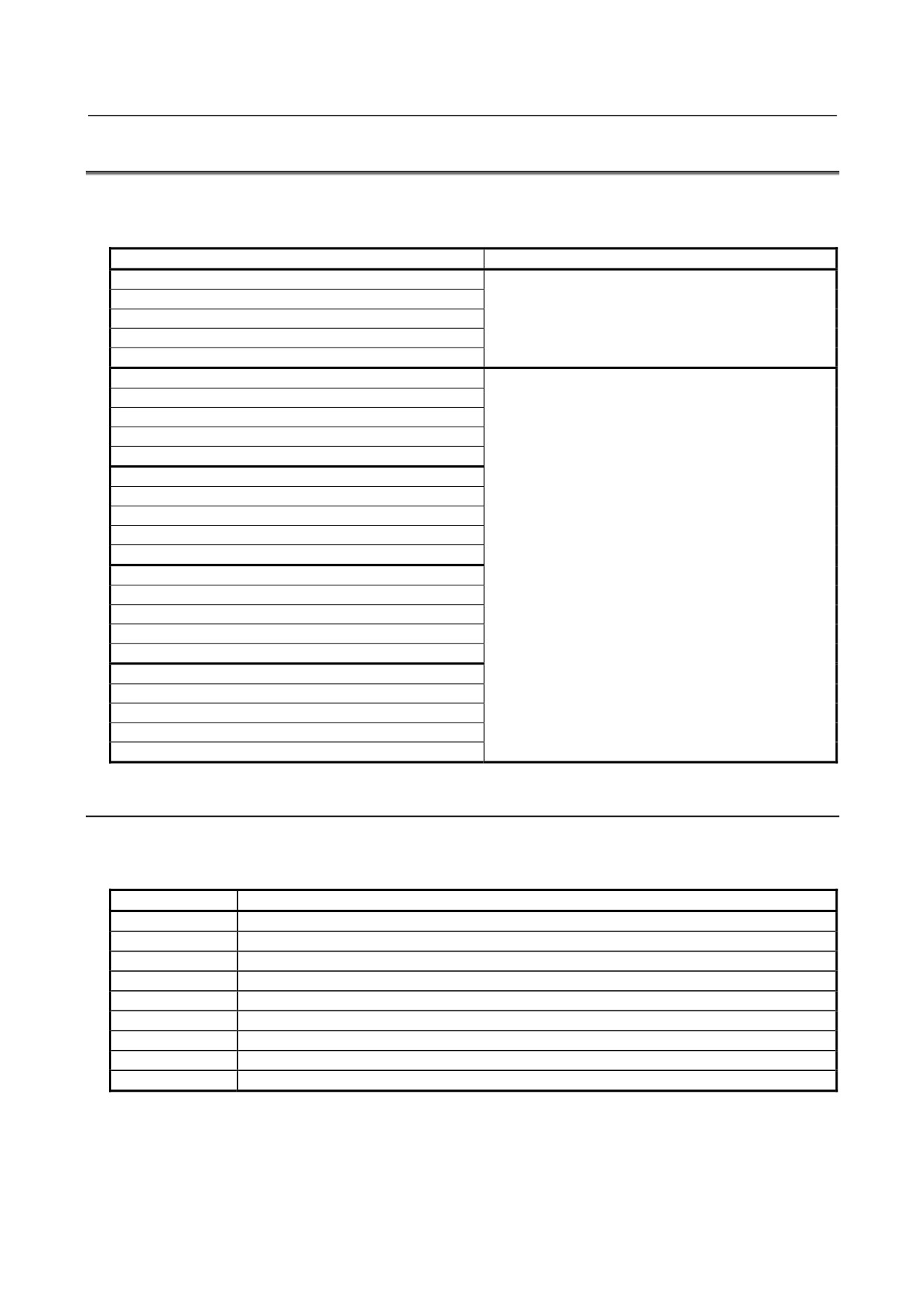
3.3
I/O FORMATS
This section describes the I/O formats of parameters.
Parameters are classified by data format as follows:
Data format
Remarks
Bit
Bit machine group
Data of these formats is represented by an 8-digit
Bit path
binary number, with each digit corresponding to a bit.
Bit axis
Bit spindle
Byte
Byte machine group
Byte path
Byte axis
Byte spindle
Word
Word machine group
Word path
Word axis
The setting range of data varies from one parameter
Word spindle
to another.
2-word
For details, refer to the description of each parameter.
2-word machine group
2-word path
2-word axis
2-word spindle
Real
Real machine group
Real path
Real axis
Real spindle
3.3.1
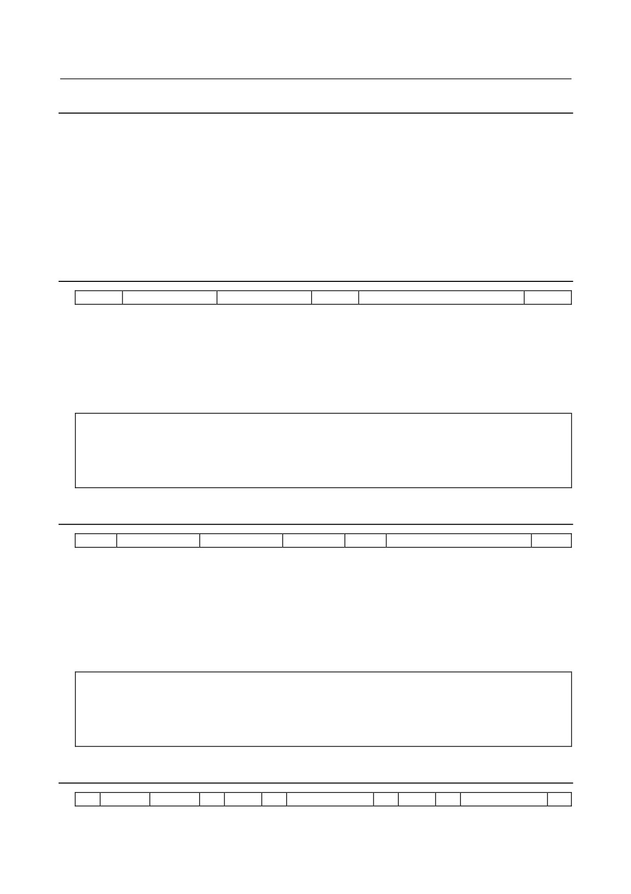
Keywords
The alphabetic characters listed below are used as keywords.
A numeric value after each keyword has the following meaning:
Keyword
Meaning of a numeric value that follows
N
Parameter number
Q
Data identifier (1: Parameter data, 0: Pitch error compensation data)
T
Machine group number (1) of a machine group type parameter
L
Path number (1 to number of controlled paths) of a path type parameter
A
Controlled axis number (1 to number of controlled axes) of an axis type parameter
S
Spindle number (1 to number of controlled spindles) of a spindle type parameter
P
Value of a parameter independent of inch/metric switching
M
Metric input value of a parameter dependent on inch/metric switching
I
Inch input value of a parameter dependent on inch/metric switching
- 6 -
3.INPUTTING AND OUTPUTTING PARAMETERS
B-64310EN/02
THROUGH THE READER/PUNCHER INTERFACE
3.3.2
Inch/Metric Switching
For parameters dependent on inch/metric switching such as those for length and feedrate, whether data is
inch data or metric data is specified by the input mode in the case of input from the MDI panel, or by the
keyword I or M prefixed to the data in the case of input from an external I/O device. The keyword I or M
is added also when data is output from an external I/O device.
If the input mode or keyword differs from the actually used mode as in a case where data input in the inch
mode is used in the metric mode, the CNC performs automatic data conversion. So, data need not be
converted according to a mode change. Moreover, when parameter data is displayed, the data is converted
according to the display mode. However, when data is output from an external I/O device, the original
data is output according to the original keyword.
3.3.3
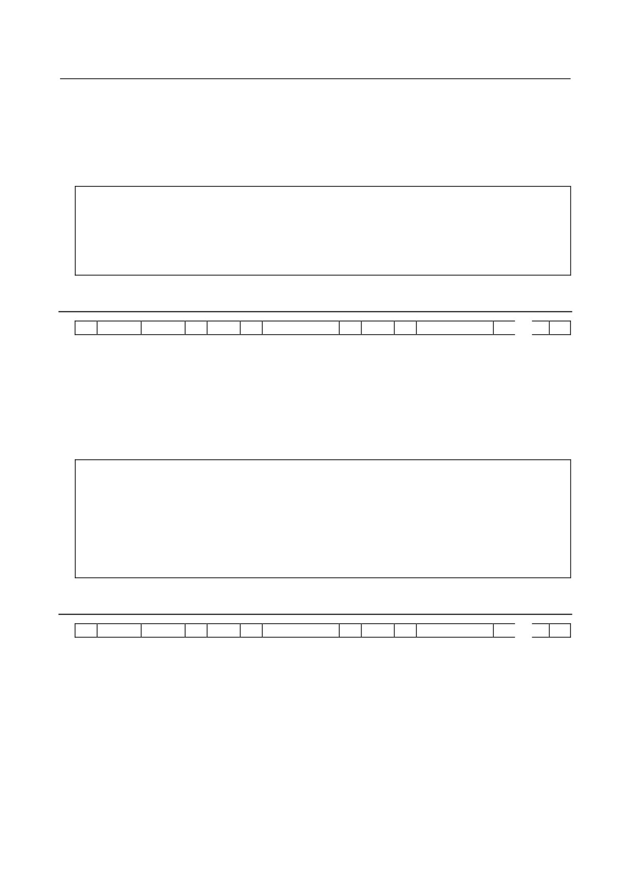
Bit Format
N
*****
Q1
P
********
;
A numeric value after N represents a parameter number.
Q1 indicates that the data is parameter data.
An 8-digit binary number after P represents the bit values (0/1) of a parameter, with the first digit
corresponding to bit 0 and the eighth digit corresponding to bit 7.
Leading zeros may not be omitted.
A semicolon (;) marks the end of a block. (LF is used for the ISO code, and CR is used for the EIA code.)
Example
N00010Q1P00000001;
Parameter No.
10
Parameter value
Bit 0 is set to 1, and the other bits are set to 0.
3.3.4
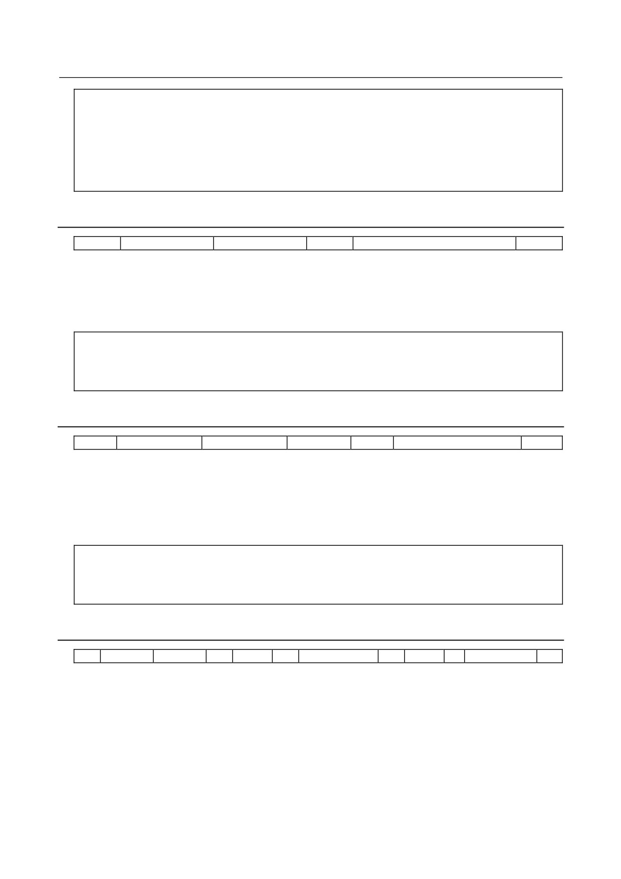
Bit Machine Group Format
N
*****
Q1
T1
P
********
;
A numeric value after N represents a parameter number.
Q1 indicates that the data is parameter data.
T1 indicates the 1st machine group (for the 0i-D/0i Mate-D, the 1st machine group is always assumed).
The 8-digit binary number that follows P includes the bit values (0 or 1) of the parameter in the 1st
machine group; the first bit corresponds to bit 0 and the eighth bit to bit 7.
Leading zeros may not be omitted.
A semicolon (;) marks the end of a block. (LF is used for the ISO code, and CR is used for the EIA code.)
Example
N01005Q1T1P10000001;
Parameter No.
1005
Parameter value
1st machine group: Bits 0 and 7 are set to 1, and the other bits are set to 0.
3.3.5
Bit Path Format
N
*****
Q1
L
*
P
********
L
*
P
********
;
A numeric value after N represents a parameter number.
- 7 -
3. INPUTTING AND OUTPUTTING PARAMETERS
THROUGH THE READER/PUNCHER INTERFACE
B-64310EN/02
Q1 indicates that the data is parameter data.
A numeric value after L represents a path number (1 to number of controlled paths).
An 8-digit binary number after P represents the bit values (0/1) of a parameter for each path, with the first
digit corresponding to bit 0 and the eighth digit corresponding to bit 7.
Leading zeros may not be omitted.
A semicolon (;) marks the end of a block. (LF is used for the ISO code, and CR is used for the EIA code.)
Example
N01005Q1L1P10000001L2P10000001;
Parameter No.
1005
Parameter value
Path 1:
Bits 0 and 7 are set to 1, and the other bits are set to 0.
Path 2:
Bits 0 and 7 are set to 1, and the other bits are set to 0.
3.3.6
Bit Axis Format
N
*****
Q1
A
P
********
A
P
********
・
・
・
;
A numeric value after N represents a parameter number.
Q1 indicates that the data is parameter data.
A numeric value after A represents a controlled axis number (1 to number of controlled axes).
An 8-digit binary number after P represents the bit values (0/1) of a parameter for each controlled axis,
with the first digit corresponding to bit 0 and the eighth digit corresponding to bit 7.
Leading zeros may not be omitted.
A semicolon (;) marks the end of a block. (LF is used for the ISO code, and CR is used for the EIA code.)
Example
N01005Q1A1P10000001A2P10000001A3P10000001
;
Parameter No.
1005
Parameter value
1st axis:
Bits 0 and 7 are set to 1, and the other bits are set to 0.
2nd axis:
Bits 0 and 7 are set to 1, and the other bits are set to 0.
3rd axis:
Bits 0 and 7 are set to 1, and the other bits are set to 0.
▪
3.3.7
Bit Spindle Format
N
*****
Q1
S
P
********
S
P
********
・
・
・
;
A numeric value after N represents a parameter number.
Q1 indicates that the data is parameter data.
A numeric value after S represents a spindle number (1 to number of controlled spindles).
An 8-digit binary number after P represents the bit values (0/1) of a parameter for each spindle, with the
first digit corresponding to bit 0 and the eighth digit corresponding to bit 7.
Leading zeros may not be omitted.
A semicolon (;) marks the end of a block. (LF is used for the ISO code, and CR is used for the EIA code.)
- 8 -
3.INPUTTING AND OUTPUTTING PARAMETERS
B-64310EN/02
THROUGH THE READER/PUNCHER INTERFACE
Example
N05603Q1S1P00001000S2P00001000S3P00000000;
Parameter No.
5603
Parameter value
1st spindle: Bit 3 is set to 1, and the other bits are set to 0.
2nd spindle: Bit 3 is set to 1, and the other bits are set to 0.
3rd spindle: All bits are set to 0.
3.3.8
Byte/Word/Two-Word Format
N
*****
Q1
P
********
;
A numeric value after N represents a parameter number.
Q1 indicates that the data is parameter data.
A numeric value after P represents a parameter value (integer).
A semicolon (;) marks the end of a block. (LF is used for the ISO code, and CR is used for the EIA code.)
Example
N00100Q1P31515;
Parameter No.
100
Parameter value
31515
3.3.9
Byte/Word/Two-Word Machine Group Format
N
*****
Q1
T1
P
******
;
A numeric value after N represents a parameter number.
Q1 indicates that the data is parameter data.
T1 indicates the 1st machine group (for the 0i-D/0i Mate-D, the 1st machine group is always assumed).
The value that follows P indicates the value (integer) of the parameter in 1st machine group.
A semicolon (;) marks the end of a block. (LF is used for the ISO code, and CR is used for the EIA code.)
Example
N01020Q1T1P88;
Parameter No.
1020
Parameter value
1st machine group:
88
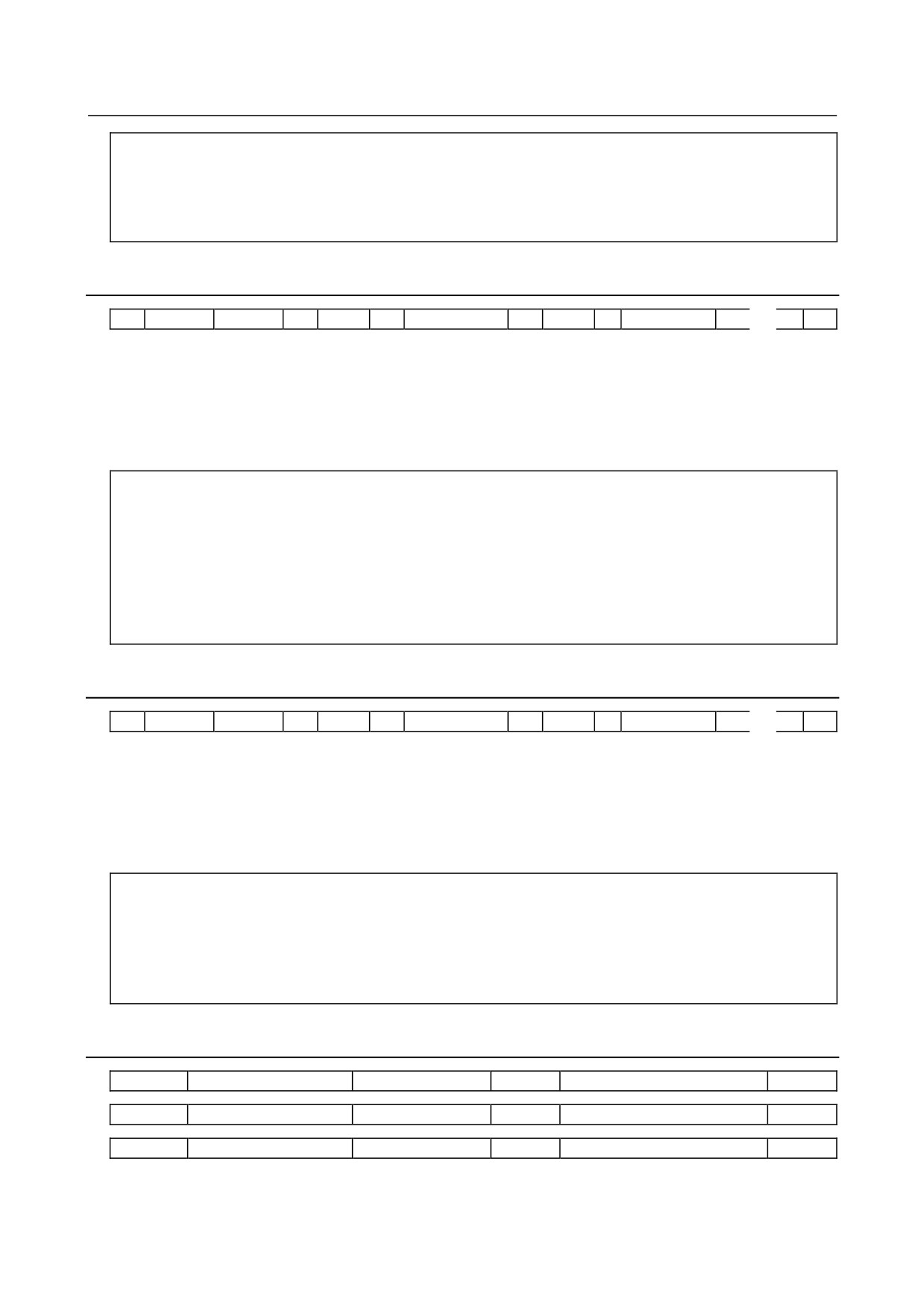
3.3.10 Byte/Word/Two-Word Path Format
N
*****
Q1
L
P
******
L
P
******
;
A numeric value after N represents a parameter number.
Q1 indicates that the data is parameter data.
A numeric value after L represents a path number (1 to number of controlled paths).
A numeric value after P represents the value (integer) of a parameter for each path.
A semicolon (;) marks the end of a block. (LF is used for the ISO code, and CR is used for the EIA code.)
- 9 -
3. INPUTTING AND OUTPUTTING PARAMETERS
THROUGH THE READER/PUNCHER INTERFACE
B-64310EN/02
Example
N01020Q1L1P88L2P89;
Parameter No.
1020
Parameter value
Path 1: 88
Path 2: 89
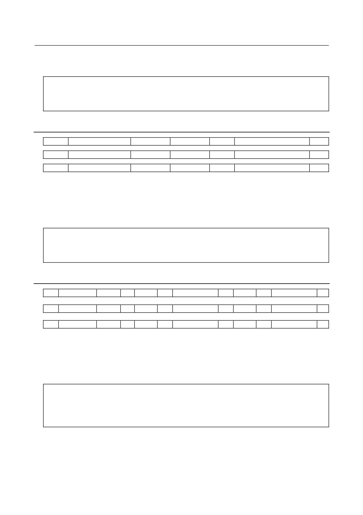
3.3.11 Byte/Word/Two-Word Axis Format
N
*****
Q1
A
P
******
A
P
******
・
・
・
;
A numeric value after N represents a parameter number.
Q1 indicates that the data is parameter data.
A numeric value after A represents a controlled axis number (1 to number of controlled axes).
A numeric value after P represents the value (integer) of a parameter for each controlled axis.
A semicolon (;) marks the end of a block. (LF is used for the ISO code, and CR is used for the EIA code.)
Example
N01020Q1A1P88A2P89A3P90A4P66
;
Parameter No.
1020
Parameter value
1st axis: 88
2nd axis: 89
3rd axis: 90
4th axis: 66
▪
3.3.12 Byte/Word/Two-Word Spindle Format
N
*****
Q1
S
P
******
S
P
******
・
・
・
;
A numeric value after N represents a parameter number.
Q1 indicates that the data is parameter data.
A numeric value after S represents a spindle number (1 and up).
A numeric value after P represents the value (integer) of a parameter for each spindle.
A semicolon (;) marks the end of a block. (LF is used for the ISO code, and CR is used for the EIA code.)
Example
N05680Q1S1P19S2P19S3P0;
Parameter No.
5680
Parameter value
1st spindle: 19
2nd spindle: 19
3rd spindle: 0
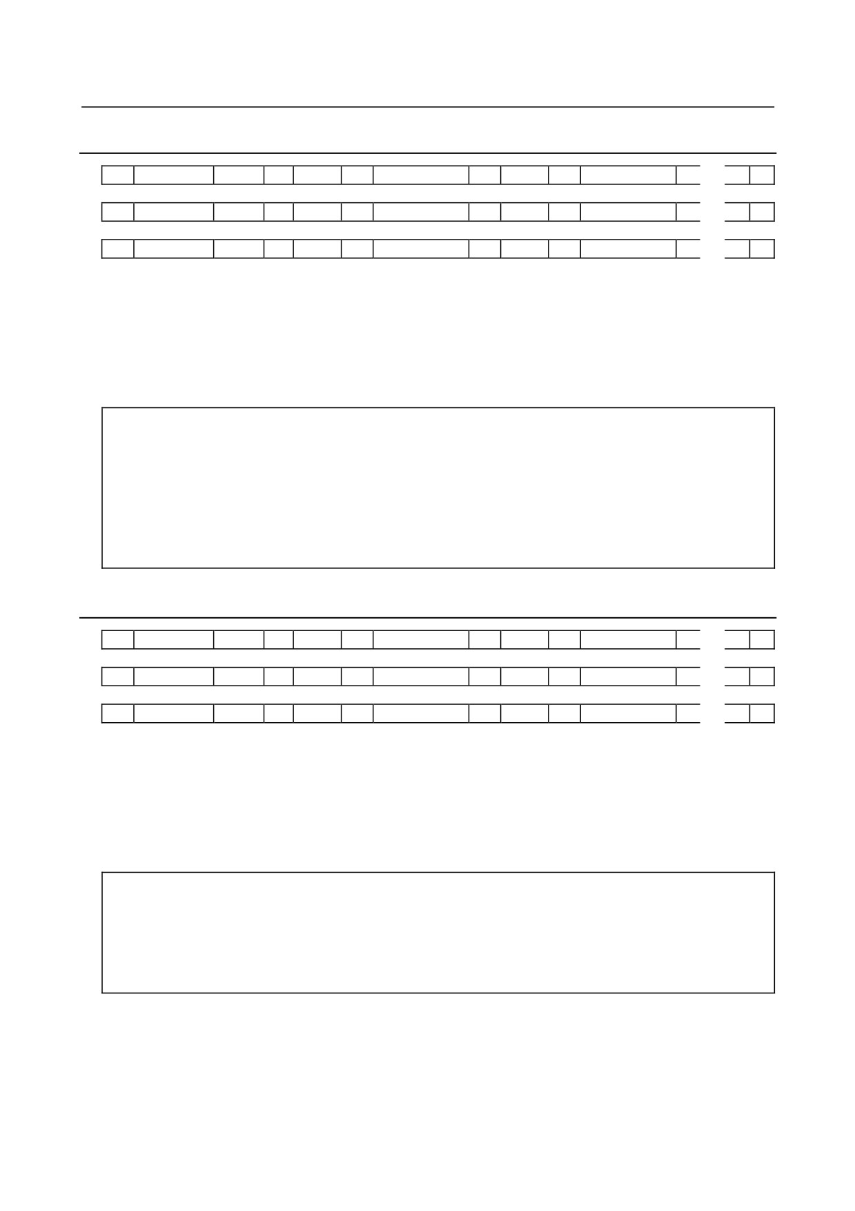
3.3.13 Real Number Format
N
*****
Q1
P
******
;
N
*****
Q1
M
******
;
N
*****
Q1
I
******
;
A numeric value after N represents a parameter number.
Q1 indicates that the data is parameter data.
- 10 -
3.INPUTTING AND OUTPUTTING PARAMETERS
B-64310EN/02
THROUGH THE READER/PUNCHER INTERFACE
A numeric value after each of P, M, and I represents the value (real number) of a parameter.
A semicolon (;) marks the end of a block. (LF is used for the ISO code, and CR is used for the EIA code.)
Example
N01451Q1P5000.0;
Parameter No.
1451
Parameter value
5000.0
3.3.14 Real Number Machine Group Format
N
*****
Q1
T1
P
******
;
N
*****
Q1
T1
M
******
;
N
*****
Q1
T1
I
******
;
A numeric value after N represents a parameter number.
Q1 indicates that the data is parameter data.
T1 indicates the 1st machine group (for the 0i-D/0i Mate-D, the 1st machine group is always assumed).
The value that follows P, M, or I indicates the value (real number) of the parameter in 1st machine group.
A semicolon (;) marks the end of a block. (LF is used for the ISO code, and CR is used for the EIA code.)
Example
N01220Q1T1M50.0;
Parameter No.
1220
Parameter value
1st machine group: 50.0
3.3.15 Real Number Path Format
N
*****
Q1
L
P
******
L
P
******
;
N
*****
Q1
L
M
******
L
M
******
;
N
*****
Q1
L
I
******
L
I
******
;
A numeric value after N represents a parameter number.
Q1 indicates that the data is parameter data.
A numeric value after L represents a path number (1 to number of controlled paths).
A numeric value after each of P, M, and I represents the value (real number) of a parameter for each path.
A semicolon (;) marks the end of a block. (LF is used for the ISO code, and CR is used for the EIA code.)
Example
N01220Q1L1M50.0L2M60.0;
Parameter No.
1220
Parameter value
Path 1: 50.0
Path 2: 60.0
- 11 -
3. INPUTTING AND OUTPUTTING PARAMETERS
THROUGH THE READER/PUNCHER INTERFACE
B-64310EN/02
3.3.16 Real Number Axis Format
N
*****
Q1
A
P
******
A
P
******
・
・
・
;
N
*****
Q1
A
M
******
A
M
******
・
・
・
;
N
*****
Q1
A
I
******
A
I
******
・
・
・
;
A numeric value after N represents a parameter number.
Q1 indicates that the data is parameter data.
A numeric value after A represents a controlled axis number (1 to number of controlled axes).
A numeric value after each of P, M, and I represents the value (real number) of a parameter for each
controlled axis.
A semicolon (;) marks the end of a block. (LF is used for the ISO code, and CR is used for the EIA code.)
Example
N01220Q1A1M50.0A2M60.0A3M70.0A4M0.0A5M0.0
;
Parameter No.
1220
Parameter value
1st axis: 50.0
2nd axis: 60.0
3rd axis: 70.0
4th axis: 0.0
5th axis: 0.0
3.3.17 Real Number Spindle Format
N
*****
Q1
S
P
******
S
P
******
・
・
・
;
N
*****
Q1
S
M
******
S
M
******
・
・
・
;
N
*****
Q1
S
I
******
S
I
******
・
・
・
;
A numeric value after N represents a parameter number.
Q1 indicates that the data is parameter data.
A numeric value after S represents a spindle number (1 to number of controlled spindles).
A numeric value after each of P, M, and I represents the value (real number) of a parameter for each
spindle.
A semicolon (;) marks the end of a block. (LF is used for the ISO code, and CR is used for the EIA code.)
Example
N05898Q1S1P30.0S2P30.0S3P0.0;
Parameter No.
5898
Parameter value
1st spindle: 30.0
2nd spindle: 30.0
3rd spindle: 0.0
- 12 -
3.INPUTTING AND OUTPUTTING PARAMETERS
B-64310EN/02
THROUGH THE READER/PUNCHER INTERFACE
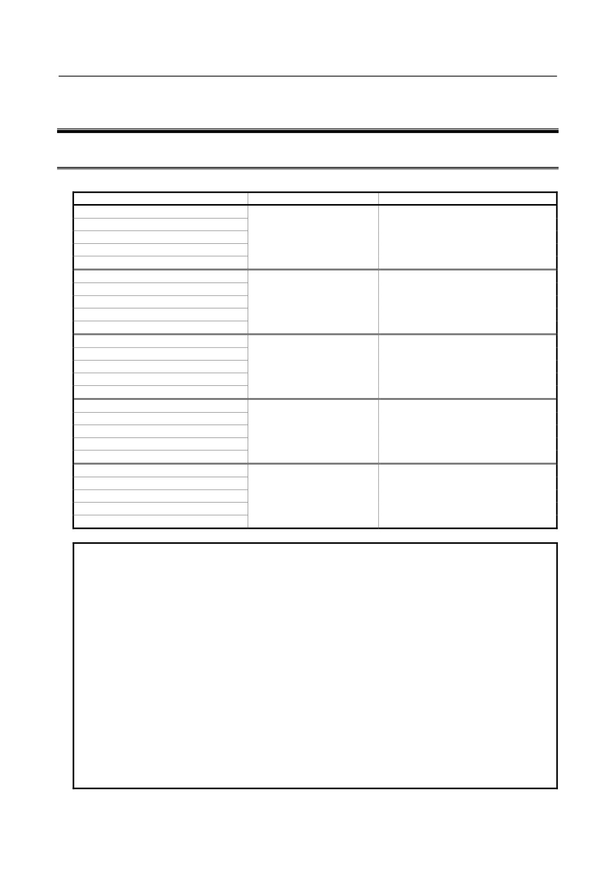
3.3.18 Start and End of a Record
A parameter record starts with "%" and ends with "%".
Example
%;
......................................... Start of record
N00000Q1P00001100;
N00002Q1P00000000;
▪
▪
N09162Q1P00000000;
N09163Q1P00000000;
%
End of record
When parameters and pitch error compensation data are included in a single file, the file starts with "%"
and ends with "%".
- 13 -
4.DESCRIPTION OF PARAMETERS
B-64310EN/02
4 DESCRIPTION OF PARAMETERS
4.1
DATA TYPE
Parameters are classified by data type as follows:
Data type
Valid data range
Remarks
Bit
Bit machine group
Bit path
0 or 1
Bit axis
Bit spindle
Byte
Byte machine group
-128 to 127
Some parameters handle these types of
Byte path
0 to 255
data as unsigned data.
Byte axis
Byte spindle
Word
Word machine group
-32768 to 32767
Some parameters handle these types of
Word path
0 to 65535
data as unsigned data.
Word axis
Word spindle
2-word
2-word machine group
Some parameters handle these types of
2-word path
0 to ±999999999
data as unsigned data.
2-word axis
2-word spindle
Real
Real machine group
See the Standard Parameter
Real path
Setting Tables.
Real axis
Real spindle
NOTE
1 Each of the parameters of the bit, bit machine group, bit path, bit axis, and bit
spindle types consists of 8 bits for one data number (parameters with eight
different meanings).
2 For machine group types, the parameters corresponding to the maximum
number of machine groups are present, so that independent data can be set for
each machine group. For the 0i -D/0i Mate-D, the maximum number of
machine groups is always 1.
3 For path types, parameters corresponding to the maximum number of paths are
present, so that independent data can be set for each path.
4 For axis types, parameters corresponding to the maximum number of control
axes are present, so that independent data can be set for each control axis.
5 For spindle types, parameters corresponding to the maximum number of
spindles are present, so that independent data can be set for each spindle axis.
6 The valid data range for each data type indicates a general range. The range
varies according to the parameters. For the valid data range of a specific
parameter, see the explanation of the parameter.
- 14 -

B-64310EN/02
4.DESCRIPTION OF PARAMETERS
4.2
REPRESENTATION OF PARAMETERS
Parameters of the bit type, bit machine group type, bit path type, bit axis type,
and bit spindle type
#7
#6
#5
#4
#3
#2
#1
#0
0000
EIA
NCR
ISP
CTV
TVC
Data No.
Data (Data #0 to #7 are bit positions.)
Parameters other than the bit-type parameters above
1023
Number of the servo axis for each axis
Data No.
Data
NOTE
1
There are bits that are indicated as a blank or parameters whose numbers are
displayed on the screen but not shown in the list in Chapter 4. "DESCRIPTION
OF PARAMETERS". Basically, set these parameters to 0.
2
Parameters that are valid only for either the lathe system (T series) or the
machining center system (M series) are indicated in two rows as shown in the
following examples. When a row is blank, the parameter is not usable with the
corresponding series. Basically, set these parameters to 0.
[Example 1]
Parameter HTG is a parameter common to the M and T series, but
Parameters RTV and ROC are parameters valid only for the T series.
#7
#6
#5
#4
#3
#2
#1
#0
RTV
HTG
ROC
T series
1403
HTG
M series
[Example 2]
The following parameter is provided only for the M series.
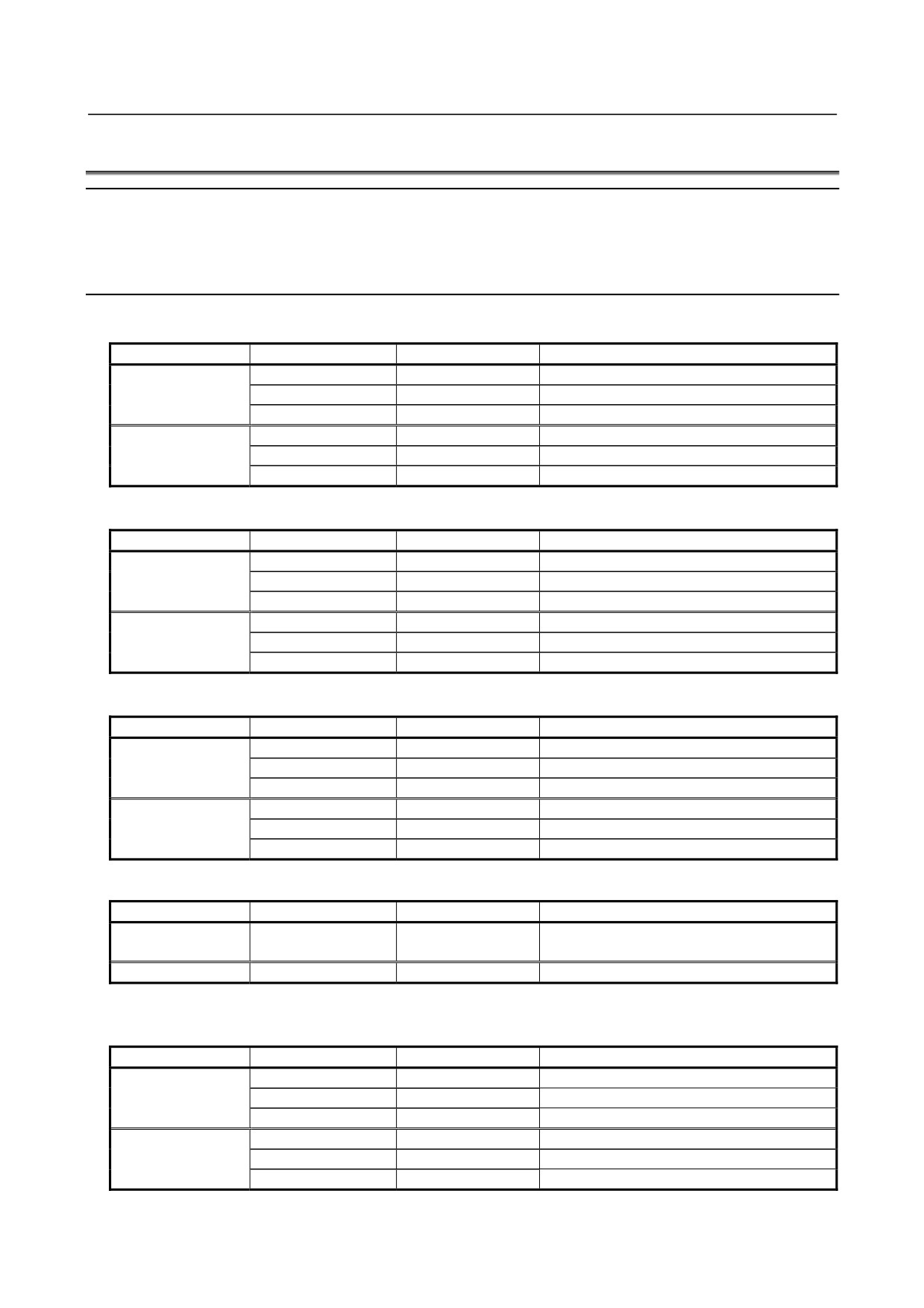
T series
1411
Cutting feedrate
M series
3
When "to" is inserted between two parameter numbers, there are parameters
with successive numbers between the two starting and ending parameter
numbers, but those intermediate parameter numbers are omitted for
convenience.
4
The lower-case letter "x" or "s" following the name of a bit-type parameter
indicates the following:
- ”
x” : Bit axis type parameters
- ”
s” : Bit spindle type parameters
- 15 -
4.DESCRIPTION OF PARAMETERS
B-64310EN/02
4.3
STANDARD PARAMETER SETTING TABLES
Overview
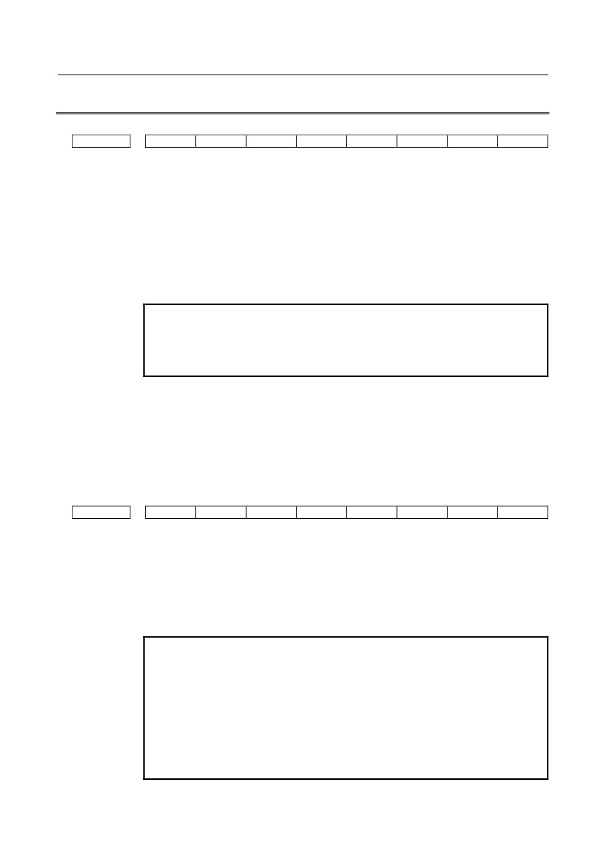
This section defines the standard minimum data units and valid data ranges of the CNC parameters of the
real type, real machine group type, real path type, real axis type, and real spindle type. The data type and
unit of data of each parameter conform to the specifications of each function.
Explanation
(A) Length and angle parameters (type 1)
Unit of data
Increment system
Minimum data unit
Valid data range
IS-A
0.01
-999999.99
to +999999.99
mm
IS-B
0.001
-999999.999
to +999999.999
deg.
IS-C
0.0001
-99999.9999
to
+99999.9999
IS-A
0.001
-99999.999
to
+99999.999
inch
IS-B
0.0001
-99999.9999
to
+99999.9999
IS-C
0.00001
-9999.99999
to
+9999.99999
(B) Length and angle parameters (type 2)
Unit of data
Increment system
Minimum data unit
Valid data range
IS-A
0.01
0.00
to +999999.99
mm
IS-B
0.001
0.000
to +999999.999
deg.
IS-C
0.0001
0.0000
to
+99999.9999
IS-A
0.001
0.000
to
+99999.999
inch
IS-B
0.0001
0.0000
to
+99999.9999
IS-C
0.00001
0.00000
to
+9999.99999
(C) Velocity and angular velocity parameters
Unit of data
Increment system
Minimum data unit
Valid data range
IS-A
0.01
0.0 to
+999000.00
mm/min
IS-B
0.001
0.0 to
+999000.000
degree/min
IS-C
0.0001
0.0 to
+99999.9999
IS-A
0.001
0.0 to
+96000.000
inch/min
IS-B
0.0001
0.0 to
+9600.0000
IS-C
0.00001
0.0 to
+4000.00000
If bit 7 (IESP) of parameter No. 1013 is set to 1, the valid data ranges for IS-C are extended as follows:
Unit of data
Increment system
Minimum data unit
Valid data range
mm/min
IS-C
0.001
0.000 to +999000.000
degree/min
inch/min
IS-C
0.0001
0.0000 to +9600.0000
(D)Acceleration and angular acceleration parameters
Unit of data
Increment system
Minimum data unit
Valid data range
IS-A
0.01
0.00
to +999999.99
mm/sec2
IS-B
0.001
0.000
to +999999.999
deg./sec2
IS-C
0.0001
0.0000
to
+99999.9999
IS-A
0.001
0.000
to
+99999.999
inch/sec
2
IS-B
0.0001
0.0000
to
+99999.9999
IS-C
0.00001
0.00000
to
+9999.99999
- 16 -

B-64310EN/02
4.DESCRIPTION OF PARAMETERS
If bit 7 (IESP) of parameter No. 1013 is set to 1, the valid data ranges for IS-C are extended as follows:
Unit of data
Increment system
Minimum data unit
Valid data range
mm/min
IS-C
0.001
0.000 to +999999.999
degree/min
inch/min
IS-C
0.0001
0.0000 to +99999.9999
Notes
(1) Values are rounded up or down to the nearest multiples of the minimum data unit.
(2) A valid data range means data input limits, and may differ from values representing actual
performance.
(3) For information on the ranges of commands to the CNC, refer to Appendix D, "LIST OF
COMMAND RANGES," in the "OPERATOR’S MANUAL" (B-64304EN).
- 17 -
4.DESCRIPTION OF PARAMETERS
B-64310EN/02
4.4
PARAMETERS OF SETTING
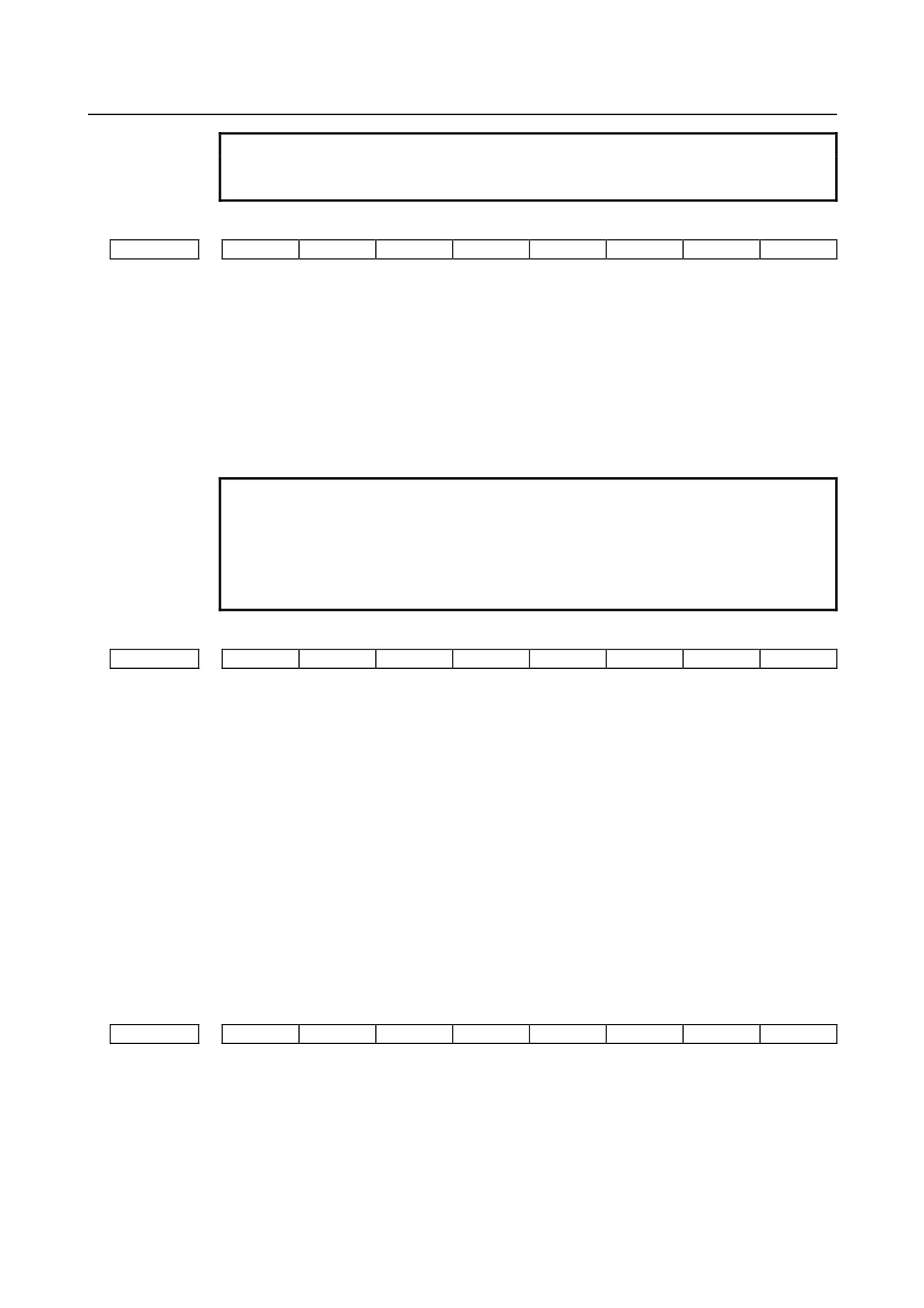
#7
#6
#5
#4
#3
#2
#1
#0
0000
SEQ
INI
ISO
TVC
[Input type] Setting input
[Data type] Bit path
#0 TVC TV check
0: Not performed
1: Performed
#1 ISO Code used for data output
0: EIA code
1: ISO code
NOTE
1 The I/O setting of a memory card is made by bit 0 (ISO) of
parameter No. 0139.
2 The I/O setting of data server is made by bit 0 (ISO) of parameter
No. 0908.
#2 INI Unit of input
0: In metrics
1: In inches
#5 SEQ Automatic insertion of sequence numbers
0: Not performed
1: Performed
#7
#6
#5
#4
#3
#2
#1
#0
0001
FCV
[Input type] Setting input
[Data type] Bit path
#1 FCV Program format
0: Series 0 standard format
(This format is compliant with the Series 0i-C.)
1: Series 10/11 format
NOTE
1 Programs created in the Series 10/11 program format can be used
for operation on the following functions:
1 Subprogram call M98,M198
2 Thread cutting with equal leads G32 (T series)
3 Canned cycle G90, G92, G94 (T series)
4 Multiple repetitive canned cycle G71 to G76 (T series)
5 Drilling canned cycle
G80 to G89 (T series)
G73, G74, G76, G80 to G89(M series)
- 18 -
B-64310EN/02
4.DESCRIPTION OF PARAMETERS
NOTE
2 When the program format used in the Series 10/11 is used for this
CNC, some limits may add. Refer to the OPERATOR’S MANUAL.
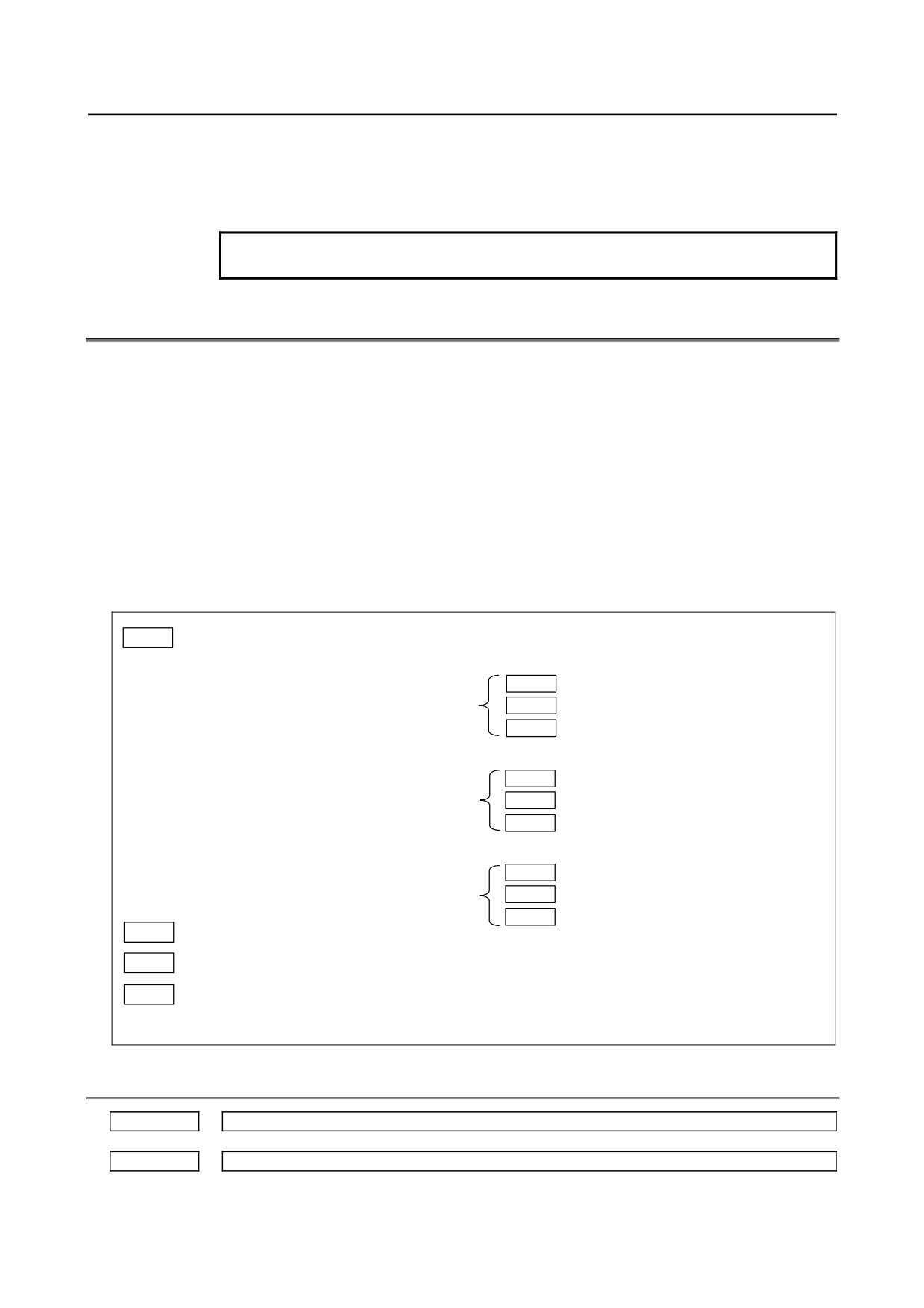
#7
#6
#5
#4
#3
#2
#1
#0
0002
SJZ
[Input type] Setting input
[Data type] Bit
#7 SJZ On an axis for which bit 3 (HJZx) of parameter No. 1005 is set:
0: If a reference position is not established yet, reference position return is performed
with deceleration dogs.
If a reference position is already established, reference position return is performed
at a parameter-set feedrate without using deceleration dogs.
1: Reference position return is performed with deceleration dogs at all times.
NOTE
SJZ is valid for an axis for which bit 3 (HJZx) of parameter No.
1005 is set to 1. When bit 1 (DLZx) of parameter No. 1005 is set to
1, however, manual reference position return after a reference
position is set is performed at a parameter-set feedrate, regardless
of the setting of SJZ.
#7
#6
#5
#4
#3
#2
#1
#0
0010
PEC
PRM
PZS
[Input type] Setting input
[Data type] Bit path
#0 PZS When a part program is punched out, the O number is:
0: Not zero-suppressed.
1: Zero-suppressed.
#1 PRM Whether the parameter whose setting is 0 is output or not:
0: It is selected with soft key [ALL] or [NON-0].
1: It is not selected with soft key [ALL] or [NON-0]. The parameter whose setting is 0
is not output.
#2 PEC When pitch error compensation data is output, the data whose value is 0 is:
0: Output.
1: Not output.
#7
#6
#5
#4
#3
#2
#1
#0
0012
RMVx
MIRx
[Input type] Setting input
[Data type] Bit axis
#0 MIRx Mirror image for each axis
0: Mirror image is off. (Normal)
1: Mirror image is on. (Mirror)
- 19 -
4.DESCRIPTION OF PARAMETERS
B-64310EN/02
#7 RMVx Releasing the assignment of the control axis for each axis
0: Not released
1: Released
(Equivalent to the control axis detachment signals DTCH1, DTCH2, and so forth)
NOTE
RMVx is valid when bit 7 (RMBx) of parameter No. 1005 is set to 1.
4.5
PARAMETERS OF READER/PUNCHER INTERFACE
To transfer data (programs, parameters, and so forth) to and from an external input/output
device through the I/O device interface
(RS-232-C serial interface), the parameters
described below need to be set.
The input/output device connected to a channel (such as RS-232-C serial port 1 and
RS-232-C serial port 2) can be selected by setting I/O CHANNEL (parameter No. 0020).
The specifications (input/output specification number, baud rate, and the number of stop
bits) of an input/output device connected to each channel must be set in the parameters
corresponding to each channel beforehand.
For channel 1, two combinations of parameters to specify the input/output device data are
provided.
The following shows the interrelation between the input/output device interface
parameters for the channels.
0020
I/O CHANNEL
Input/output channel number (parameter No.0020)
or foreground input
↓
Set channels to be used
0101
Stop bit and other data
for data input/output.
I/O CHANNEL=0
0102
Number specified for the input/output device
(Channel 1)
I/O CHANNEL (0 to 9)
0103
Baud rate
=0 : Channel 1
=1 : Channel 1
=2 : Channel 2
0111
Stop bit and other data
=3 : Channel 3
I/O CHANNEL=1
0112
Number specified for the input/output device
:
(Channel 1)
:
0113
Baud rate
:
Input/output to and from the memory card
interface, etc. is also possible.
0121
Stop bit and other data
I/O CHANNEL=2
0122
Number specified for the input/output device
When IO4 is set
(Channel 2)
0123
Baud rate
0021
Foreground output
:
0022
Background input
:
0023
:
Background input
I/O CHANNEL=9
The channel setting is the same as No.0020.
4.5.1
Parameters Common to All Channels
0020
I/O CHANNEL : Input/output device selection, or interface number for a foreground input device
0021
Foreground output device setting
- 20 -
B-64310EN/02
4.DESCRIPTION OF PARAMETERS
0022
Background input device setting
0023
Background output device setting
[Input type] Setting input
[Data type] Byte
[Valid data range] 0 to 9
The CNC has the following interfaces for transferring data to and from an external
input/output device and the host computer:
• Input/output device interface (RS-232-C serial ports 1 and 2)
• Memory card interface
• Data server interface
• Embedded Ethernet interface
By setting bit
0 (IO4) of parameter No. 0110, data input/output can be controlled
separately. When IO4 is not set, data input/output is performed using the channel set in
parameter No. 0020. When IO4 is set, a channel can be assigned to each of foreground
input, foreground output, background input, and background output.
In these parameters, specify the interface connected to each input/output device to and
from which data is to be transferred. See the table below for these settings.
To execute the DNC operation or M198 command with FOCAS2/Ethernet, set this
parameter to 6.
Correspondence between settings and input/output devices
Setting
Description
0,1
RS-232-C serial port 1
2
RS-232-C serial port 2
4
Memory card interface
5
Data server interface
6
Execution of the DNC operation or M198 command with FOCAS2/Ethernet
9
Embedded Ethernet interface
Setting of communication with the ladder development tool (FANUC LADDER-III, ladder editing
0024
package)
[Input type] Setting input
[Data type] Word
[Valid data range] 0 to 255
This parameter is used to enable or disable the PMC online connection function.
By specifying this parameter, the PMC online connection function can be enabled or
disabled without displaying the PMC online setting screen.
Setting
RS-232-C
High-speed interface
0
The setting on the PMC online setting screen is not altered.
1
To be used (channel 1)
Not to be used
2
To be used (channel 2)
Not to be used
10
Not to be used
To be used
11
To be used (channel 1)
To be used
12
To be used (channel 2)
To be used
255
Communication is terminated forcibly (as with the [FORCED STOP] soft key).
- 21 -
4.DESCRIPTION OF PARAMETERS
B-64310EN/02
NOTE
1 The setting of this parameter becomes valid when the power is
turned on or this parameter is modified. After this parameter is set,
the power need not be turned off then back on.
2 A setting modification made on the PMC online setting screen is
not reflected in this parameter.
3 The communication settings of a baud rate and so forth for using
RS-232-C made on the PMC online setting screen are valid. When
no modification is ever made to the settings on the PMC online
setting screen, the baud rate is 9600, parity is not used, and the
number of stops bits is 2.
4 Be sure to set 255 in this parameter to change the state of the
PMC online connection function from valid to invalid. Even if 0 is
set in this parameter, the function does not become invalid.
5 When the PMC online connection function occupies RS-232C or
High-speed interface, if other functions try to use RS-232C or
High-speed interface, warning "CANNOT USE I/O DEVICE" is
issued.
#7
#6
#5
#4
#3
#2
#1
#0
0100
ENS
IOP
NCR
CRF
CTV
[Input type] Setting input
[Data type] Bit
#1 CTV Character counting for TV check in the comment section of a program.
0: Performed
1: Not performed
#2 CRF Output of the end of block (EOB) in ISO code
0: Depends on the setting of bit 3 (NCR) of parameter No. 0100.
1: CR, LF are output.
#3 NCR Output of the end of block (EOB) in ISO code
0: LF, CR, CR are output.
1: Only LF is output.
#6 IOP Stopping a program output or input operation by a reset is:
0: Enabled
1: Disabled
(Stopping a program input/output operation with the [STOP] soft key is enabled at all
times.)
#7 ENS Action taken when a NULL code is found during read of EIA code
0: An alarm is generated.
1: The NULL code is ignored.
#7
#6
#5
#4
#3
#2
#1
#0
0110
IO4
[Input type] Parameter input
[Data type] Bit
- 22 -