FANUC Series 0i-MODEL D, Series 0i Mate-MODEL D. CONNECTION MANUAL (HARDWARE) - page 12
B-64303EN/03
9.CONNECTION OF I/O Link SLAVE DEVICES
9.12 CONNECTION OF THE I/O LINK-AS-i CONVERTER
9.12.1 Overview
The FANUC I/O Link-AS-i converter unit (hereinafter referred to as the AS-i converter) is a stand-alone
unit that converts I/O Link data to the Actuator Sensor Interface (hereinafter referred to as the AS-i),
which is an I/O-level open network.
9.12.1.1 Features
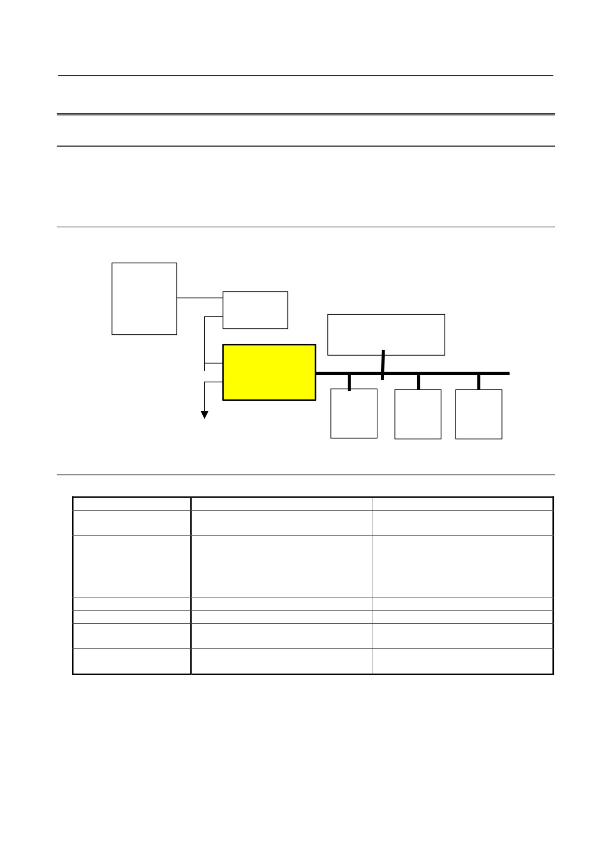
The AS-i converter converts the AS-i to the I/O Link so that the DI/DO signals of an AS-i slave module
can be used by the PMC of a CNC that has the I/O Link.
CNC
I/O LINK
I/O Unit
AS-i power supply
(commercially available)
I/O Link
I/O Link- AS-i
AS-i
converter unit
AS-i slave
AS-i slave
AS-i slave
(commercially
(commercially
(commercially
available)
available)
available)
9.12.1.2 AS-i versions and ordering information
Two major versions of the AS-i are available: Ver. 2.0 and Ver. 2.1.
AS-i version
Ver. 2.0
Ver. 2.1
Maximum number of I/O
124 input points/124 output points
248 input points/186 output points
points
Maximum number of
31 (standard slave)
62 (A/B slave)
slaves
Caution) When standard slaves such as
analog slaves are used, the maximum
number of slaves is 31.
Maximum cable length
100 m
100 m
Cycle time
5 ms/31 units
10 ms/62 units
Analog input/output
The user needs to make a data control
Input/output can be performed easily with
sequence.
a command.
Ordering information of
A03B-0817-C001
A03B-0817-C002
the AS-i converter
- 317 -
9.CONNECTION OF I/O Link SLAVE DEVICES
B-64303EN/03
9.12.1.3 Applicable CNC
The AS-i converter can be used when any of the following CNCs is used as the master of the I/O Link.
Series 0i/15i/16i/8i/30i/31i/2i/Power Mate i-D/H
NOTE
Note that when the AS-i converter is used, a large number of I/O points are
occupied on the I/O Link side as described in Subsection 9.12.4.
9.12.1.4 Specification of the I/O Link side
For Ver. 2.0
For Ver. 2.1
A03B-0817-C001
A03B-0817-C002
Number of occupied
256 input points/256 output points
512 input points/512 output points
points
Note) Two successive groups are occupied.
9.12.1.5 Support for AS-i profiles
For Ver. 2.0
For Ver. 2.1
A03B-0817-C001
A03B-0817-C002
Master profile
Equivalent to M1
Equivalent to M1e
Analog profile
7.1 / 7.2
7.3 / 7.4
Note) The user needs to make a data control sequence.
9.12.2 Specifications
9.12.2.1 Specifications of the AS-i converter
Power supply
Input power supply: 24 VDC (±10%)
For Ver. 2.0
For Ver. 2.1
A03B-0817-C001
A03B-0817-C002
Power supply capacity
100 mA
120 mA
Heat dissipation
2.4 W
2.9 W
Weight
For Ver. 2.0
For Ver. 2.1
A03B-0817-C001
A03B-0817-C002
350 g
370 g
- 318 -
B-64303EN/03
9.CONNECTION OF I/O Link SLAVE DEVICES
9.12.2.2 Installation conditions
Ambient temperature
Operation: 0°C to 55°C
for the module
Storage and transportation: -20°C to 60°C
Temperature change
1.1°C/minute maximum
Humidity
Normal condition: 75% (relative humidity)
Short term (within one month): 95% (relative humidity)
Vibration
Operation: 0.5 G or less
Non-operation: 1.0 G or less
FANUC performs evaluation test under the following conditions:
10 Hz to 58 Hz: 0.075 mm (amplitude)
58 Hz to 500 Hz: 1 G
Vibration direction: X, Y, and Z
Number of sweeps: 10 cycles
Compliance with IEC60068-2-6
Atmosphere
Normal machining factory environment (For use in an environment with relatively high
levels of dust, coolant, organic solutions, and so forth, additional measures are required.)
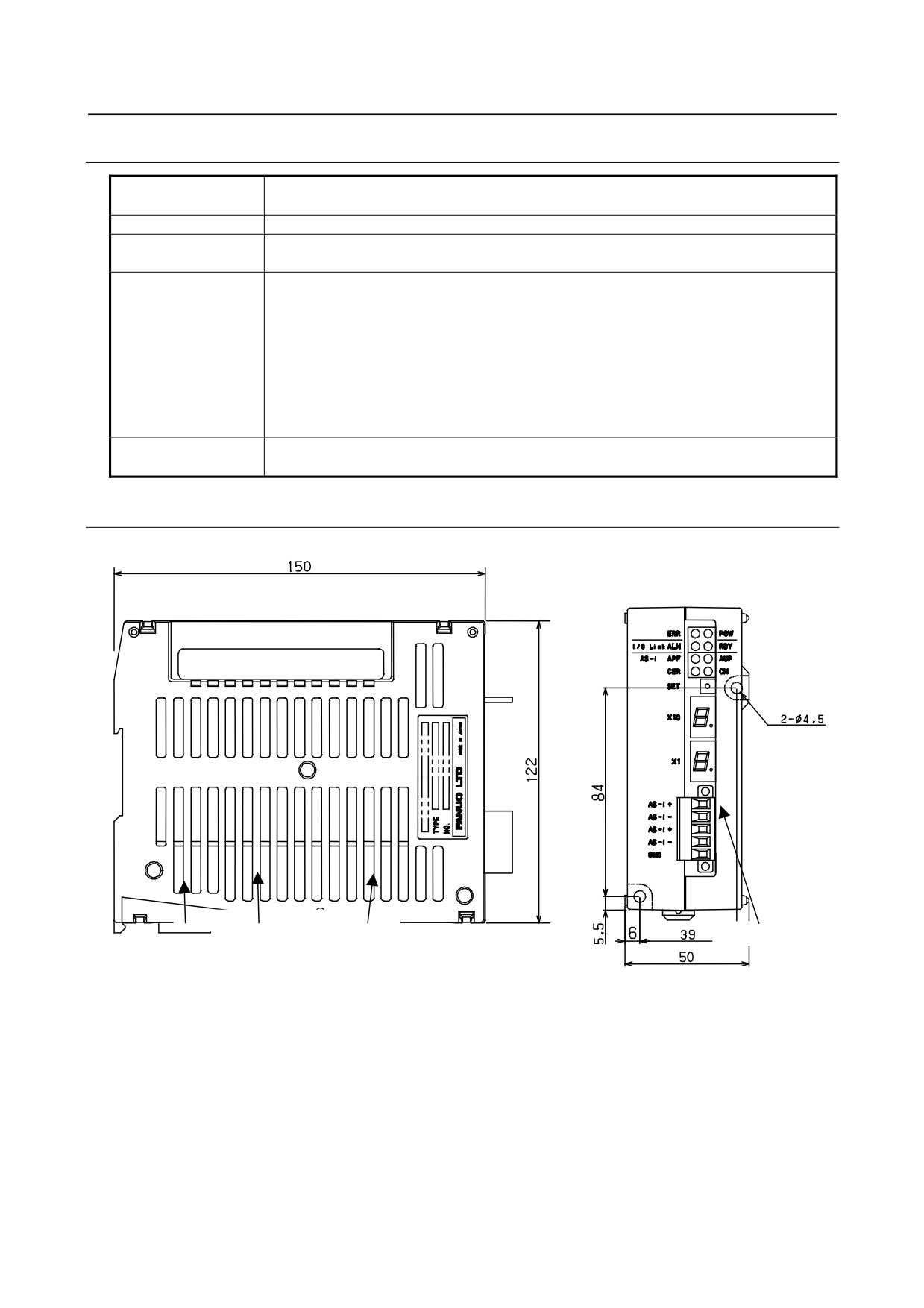
9.12.2.3 Dimensions and connector layout
Unit: mm
CP1
JD1A
JD1B
AS-i terminal block
- 319 -
9.CONNECTION OF I/O Link SLAVE DEVICES
B-64303EN/03
9.12.2.4 Installation
Notes on installation
(1) Use the unit in a completely sealed cabinet.
(2) Be sure to install the unit on a vertical plane and allow a clearance of 100 mm or more above and
below the unit. Do not place a device that generates a large amount of heat below the unit.
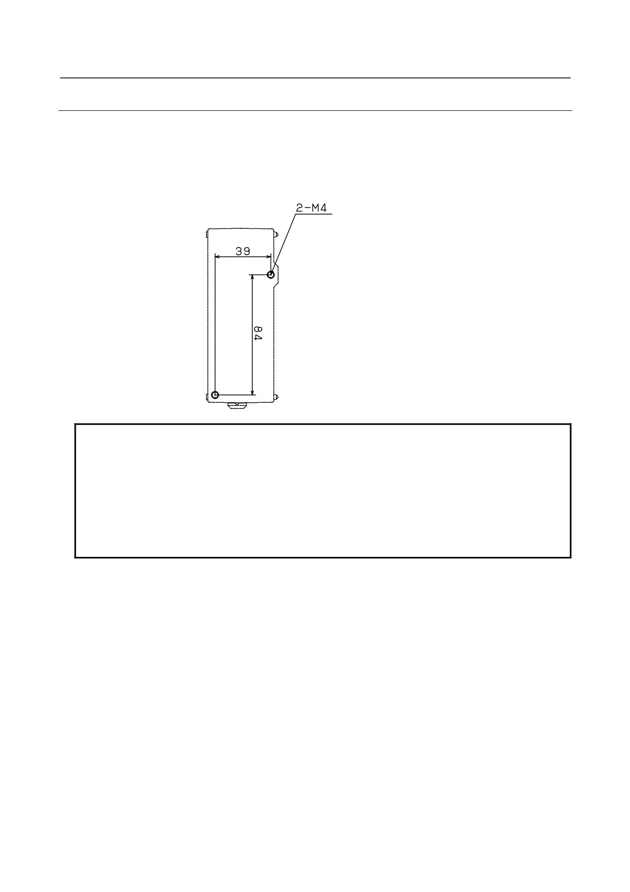
Mounting hole for screwing
Front view of the unit
Unit: mm
NOTE
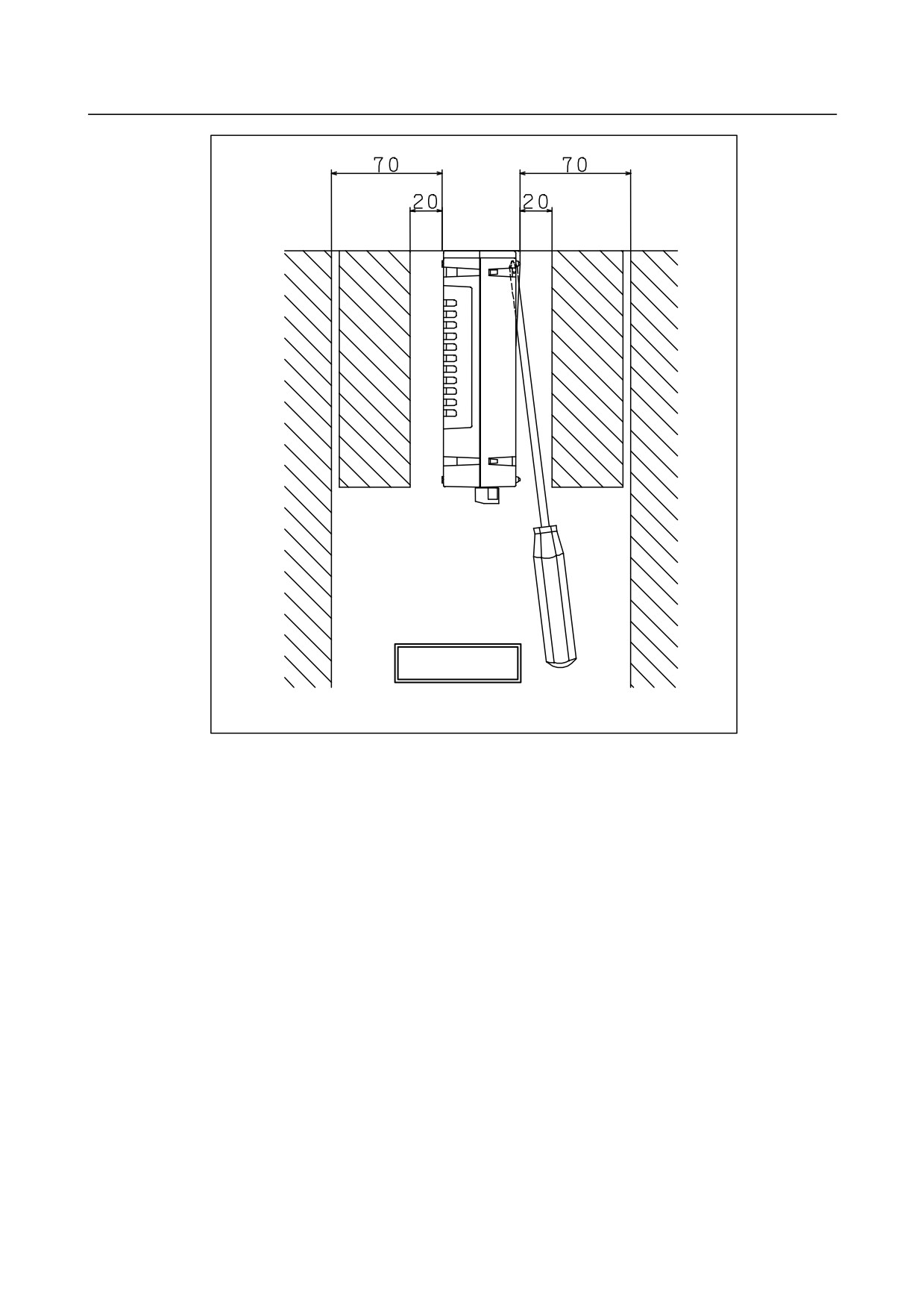
1 A screwdriver is inserted on a slant to mount and dismount the unit, so that a
sufficient maintenance space is required on both sides of the unit. When the
front face of an adjacent unit is flush with the front face of the unit or is recessed,
provide a clearance of about 20 mm from the adjacent unit. When the front face
of an adjacent unit is more projected toward you than the front face of the unit,
provide a clearance of about 70 mm from the adjacent unit.
2 When the unit is to be installed near a side plane of the cabinet, provide a
clearance of about 70 mm between the unit and the side plane of the cabinet.
- 320 -
B-64303EN/03
9.CONNECTION OF I/O Link SLAVE DEVICES
Unit: mm
View from top
- 321 -
9.CONNECTION OF I/O Link SLAVE DEVICES
B-64303EN/03
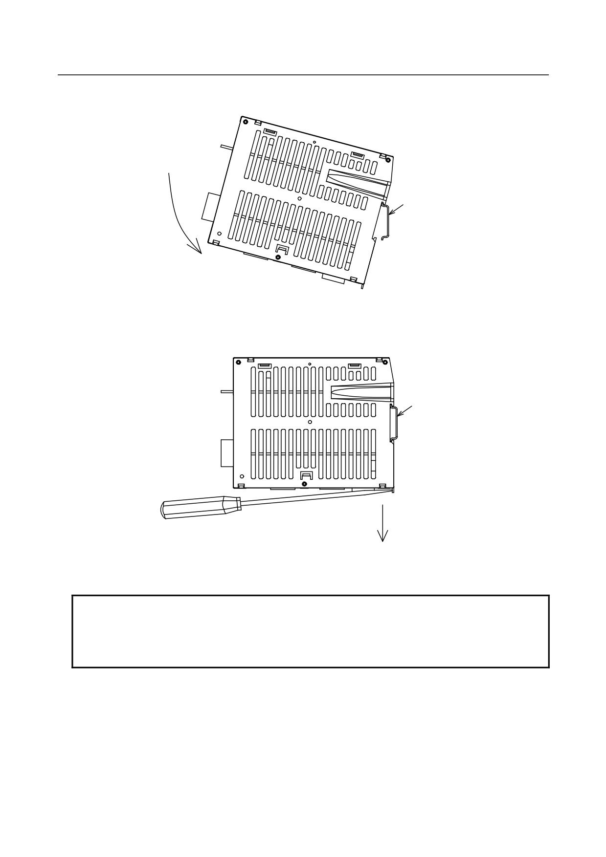
Using a DIN rail for mounting
1) Method of mounting
DIN rail
1. Place the hook of the unit onto the top of the DIN rail.
2. Push the unit until it clicks into place.
2) Method of dismounting
DIN rail
1. Lower the locking section with a flat-blade screwdriver.
2. Pull the lower part of the unit toward you.
NOTE
When dismounting the unit, be careful not to damage the locking section by
applying an excessive force. When mounting and dismounting the unit, hold the
unit by its top and bottom surfaces. Avoid applying force to the sides (where slits
are provided).
- 322 -
B-64303EN/03
9.CONNECTION OF I/O Link SLAVE DEVICES
9.12.3 Connection
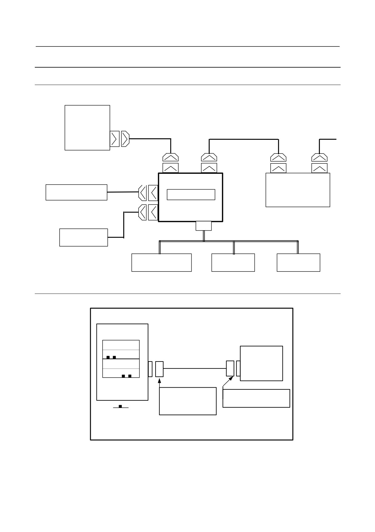
9.12.3.1 Overall connection diagram
CNC
I/O Link
FANUC I/O Link
JD51A
JD1B
JD1A
JD1B
JD1A
CP1
24 VDC power supply
AS-i converter
I/O Unit, etc.
CP1 Terminal block
CP1
AS-i cable
External device
AS-i power supply
AS-i slave
AS-i slave
9.12.3.2 Power connection
Supply power to the AS-i converter from the CNC or an external 24 VDC regulated power supply.
AS-i converter
CP1
For branch output
24 VDC power supply
B1 B2 B3
Connected for input
Regulated
+24E 0V
power supply
A1 A2 A3
24 VDC ±10%
+24
0V
For input
Tyco Electronics AMP
Make a selection matching
1-178288-3 (housing)
the power supply used.
1-175218-5 (contact)
Key arrangement
Recommended cable (for using external power):
A02B-0124-K830
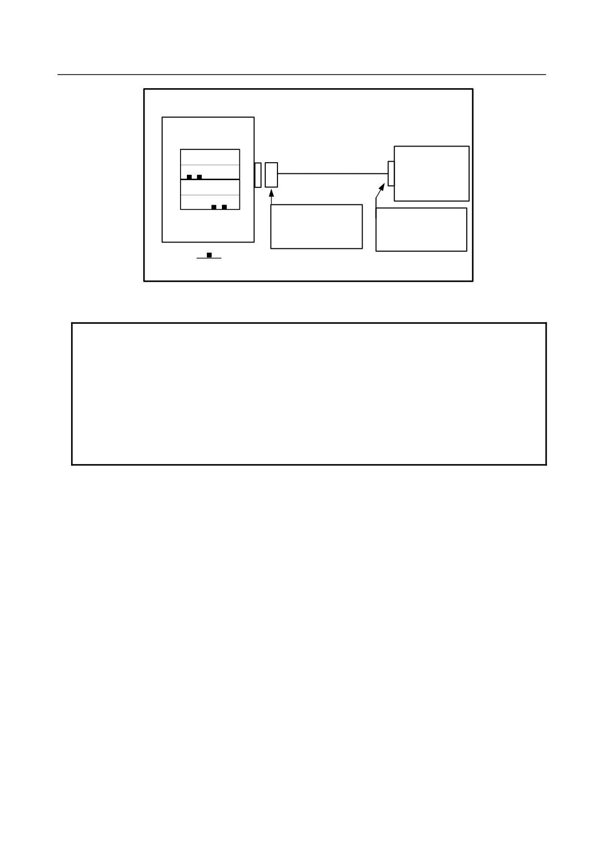
The 24 VDC input to CP1 (A1, A2) can be output from CP1 (B1, B2) for branching. CP1 (B1, B2) is
connected as shown below. In this case, the external 24 VDC power supply needs to provide CP1 (A1,
A2) with a current which is equal to the sum of the current consumed by the control unit and the current
used via CP1 (B1, B2).
- 323 -
9.CONNECTION OF I/O Link SLAVE DEVICES
B-64303EN/03
AS-i converter
CP1
For branch output
External device
B1
B2 B3
Connected for branch output
+24E 0V
A1 A2 A3
+24
0V
Tyco Electronics AMP
Make a selection
For input
2-178288-3 (housing)
matching the external
1-175218-5 (contact)
device.
Key arrangement
The DC output current supplied from CP1 (B1, B2) is 1 A maximum.
NOTE
1 Ensure that +24 V is supplied either when or before the power to the CNC is
turned on, and that +24 V is removed either when or after the power to the CNC
is turned off.
2 When turning off the power to the CNC control unit, be sure to turn off the power
to the AS-i converter and other slave I/O units connected via the I/O Link as well.
3 Turn on the power to the AS-i power supply (power supply connected to the AS-i
communication cable) either when or before the power to the CNC control unit is
turned on. If the power to the AS-i power supply is turned on after the power to
the CNC control unit is turned on, the system may not be started.
- 324 -
B-64303EN/03
9.CONNECTION OF I/O Link SLAVE DEVICES
9.12.3.3 I/O Link connection
Refer to the connection manual of the control unit to be connected. The same connection method applies
to all units connected to the I/O Link.
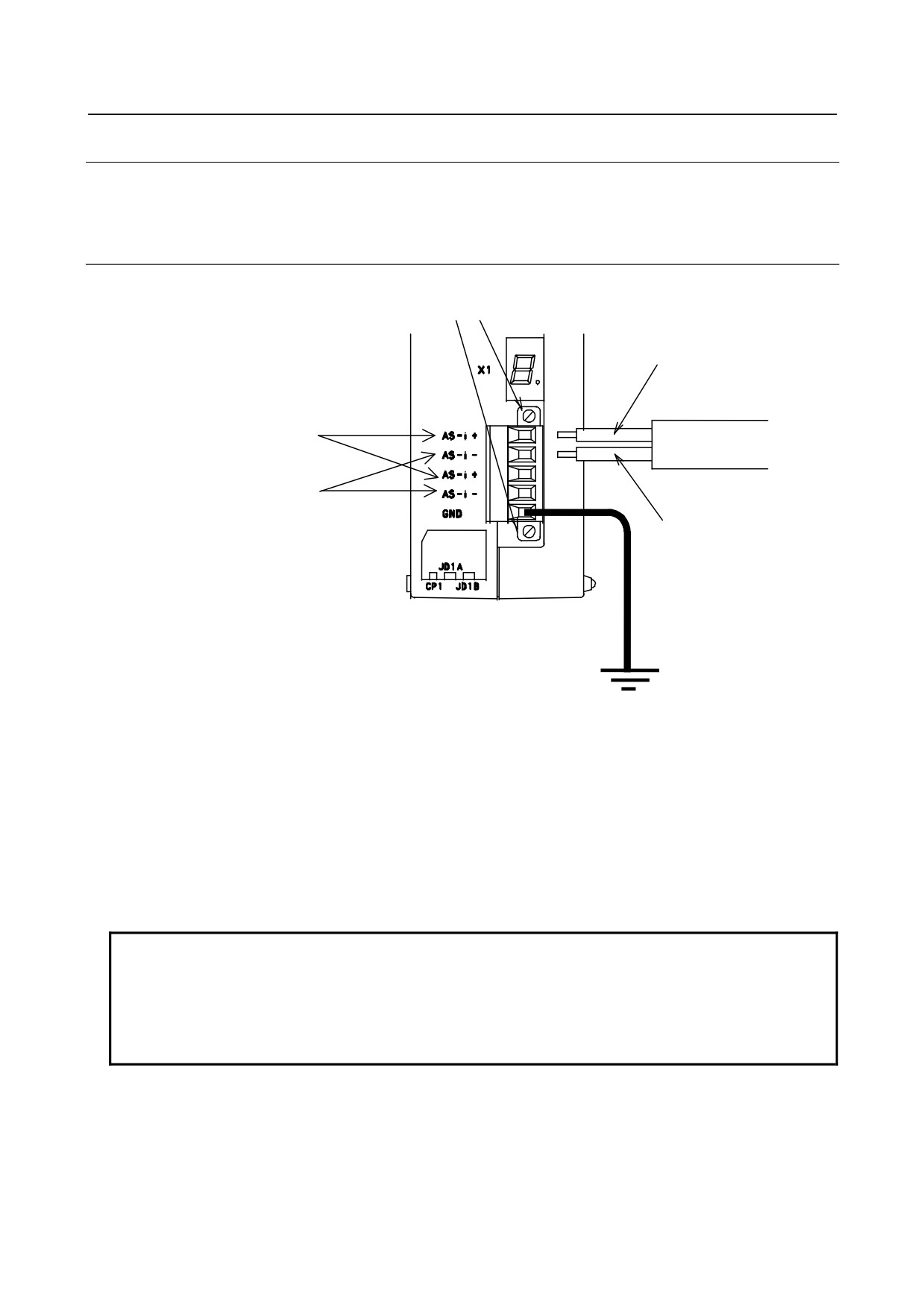
9.12.3.4 AS-i connection
Terminal block mounting screw
+: Brown
The two (+) terminals and
AS-i cable
the two (−) terminals are
connected with each
other in the AS-i
converter.
-: Blue
1)
Peel off the coating of the AS-i cable then screw the cable onto the terminal block of the AS-i
converter.
2)
This terminal block is detachable, and work can be done on the terminal block after being detached
from the AS-i converter. When attaching the terminal block, firmly tighten the screws for mounting
the terminal block.
3)
To facilitate AS-i cable branching, two AS-i + terminals and two AS-i − terminals are provided. A +
terminal and a − terminal are connected with each other in the AS-i converter. Use those terminals
that can be handled more easily.
4)
Do not connect two cables to each terminal.
5)
Connect the GND terminal to ground.
NOTE
To protect against induction noise, separate high-voltage lines and the power
line from the AS-i communication cable as much as possible. (It is
recommended to separate high-voltage lines and the power line from the AS-i
communication cable by 300 mm or more.) Moreover, attach a surge absorber to
a device that tends to generate noise.
- 325 -
9.CONNECTION OF I/O Link SLAVE DEVICES
B-64303EN/03
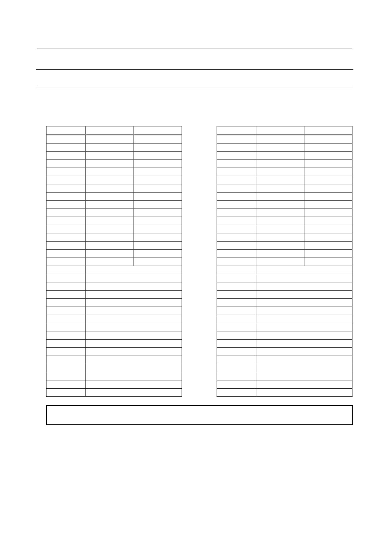
9.12.4 DI/DO Mapping on the I/O Link
9.12.4.1 For AS-i Ver. 2.0 (A03B-0817-C001)
On the I/O Link, 32 bytes are assigned for input and 32 bytes are assigned for output.
Assignment name: OC03I for input, OC03O for output
<Input>
<Output>
X
bit 7-4
bit 3-0
Y
bit 7-4
bit 3-0
+0
DI #1
Reserved
+0
DO #1
Reserved
+1
DI #3
DI #2
+1
DO #3
DO #2
+2
DI #5
DI #4
+2
DO #5
DO #4
+3
DI #7
DI #6
+3
DO #7
DO #6
+4
DI #9
DI #8
+4
DO #9
DO #8
+5
DI #11
DI #10
+5
DO #11
DO #10
+6
DI #13
DI #12
+6
DO #13
DO #12
+7
DI #15
DI #14
+7
DO #15
DO #14
+8
DI #17
DI #16
+8
DO #17
DO #16
+9
DI #19
DI #18
+9
DO #19
DO #18
+10
DI #21
DI #20
+10
DO #21
DO #20
+11
DI #23
DI #22
+11
DO #23
DO #22
+12
DI #25
DI #24
+12
DO #25
DO #24
+13
DI #27
DI #26
+13
DO #27
DO #26
+14
DI #29
DI #28
+14
DO #29
DO #28
+15
DI #31
DI #30
+15
DO #31
DO #30
+16
AS-i master status (1)
+16
Command flag
+17
AS-i master status (2)
+17
Command code
+18
Board status (1)
+18
Command parameter (1)
+19
Board status (2)
+19
Command parameter (2)
+20
Slave list (1) #1 to #7
+20
Command parameter (3)
+21
Slave list (2) #8 to #15
+21
Command parameter (4)
+22
Slave list (3) #16 to #23
+22
Reserved
+23
Slave list (4) #24 to #31
+23
Reserved
+24
Command status
+24
Reserved
+25
Command error code
+25
Reserved
+26
Command response data (1)
+26
Reserved
+27
Command response data (2)
+27
Reserved
+28
Command response data (3)
+28
Reserved
+29
Command response data (4)
+29
Reserved
+30
Reserved
+30
Reserved
+31
Reserved
+31
Reserved
NOTE
A number after # represents an AS-i slave number.
- 326 -
B-64303EN/03
9.CONNECTION OF I/O Link SLAVE DEVICES
9.12.4.2 For AS-i Ver. 2.1 (A03B-0817-C002)
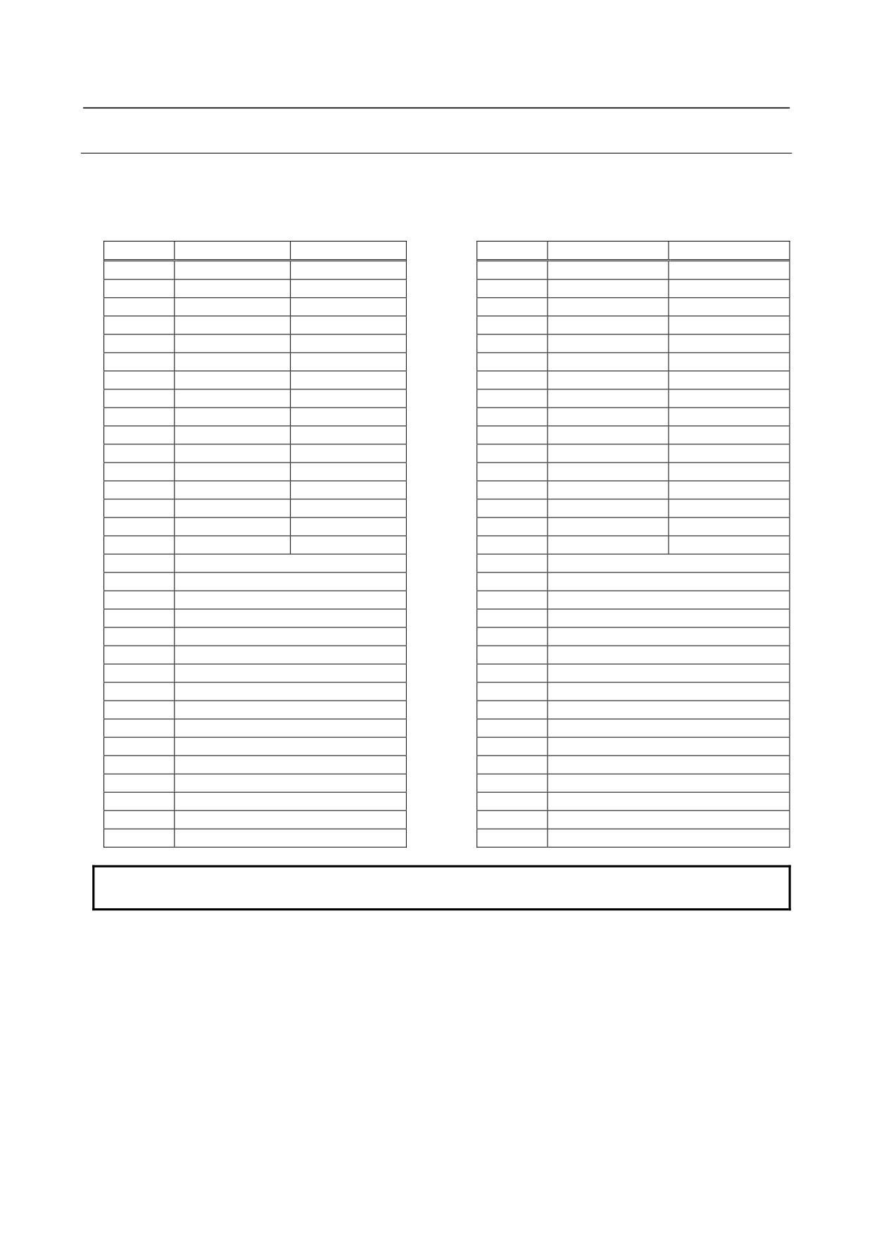
On the I/O Link, 64 bytes are assigned for input and 64 bytes are assigned for output.
Assignment name: OC03I for input, OC03O for output. Two successive groups are assigned.
<Input>
Group α
Group α+1
X
bit 7-4
bit 3-0
X'
bit 7-4
bit 3-0
+0
DI #1A
Reserved
+0
DI #1B
Reserved
+1
DI #3A
DI #2A
+1
DI #3B
DI #2B
+2
DI #5A
DI #4A
+2
DI #5B
DI #4B
+3
DI #7A
DI #6A
+3
DI #7B
DI #6B
+4
DI #9A
DI #8A
+4
DI #9B
DI #8B
+5
DI #11A
DI #10A
+5
DI #11B
DI #10B
+6
DI #13A
DI #12A
+6
DI #13B
DI #12B
+7
DI #15A
DI #14A
+7
DI #15B
DI #14B
+8
DI #17A
DI #16A
+8
DI #17B
DI #16B
+9
DI #19A
DI #18A
+9
DI #19B
DI #18B
+10
DI #21A
DI #20A
+10
DI #21B
DI #20B
+11
DI #23A
DI #22A
+11
DI #23B
DI #22B
+12
DI #25A
DI #24A
+12
DI #25B
DI #24B
+13
DI #27A
DI #26A
+13
DI #27B
DI #26B
+14
DI #29A
DI #28A
+14
DI #29B
DI #28B
+15
DI #31A
DI #30A
+15
DI #31B
DI #30B
+16
AS-i master status (1)
+16
Reserved
+17
AS-i master status (2)
+17
Reserved
+18
Board status (1)
+18
Reserved
+19
Board status (2)
+19
Reserved
+20
Slave list (1) #1A to #7A
+20
Slave list (5) #1B to #7B
+21
Slave list (2) #8A to #15A
+21
Slave list (6) #8B to #15B
+22
Slave list (3) #16A to #23A
+22
Slave list (7) #16B to #23B
+23
Slave list (4) #24A to #31A
+23
Slave list (8) #24B to #31B
+24
Command status
+24
Reserved
+25
Command error code
+25
Reserved
+26
Command response data (1)
+26
Command response data (5)
+27
Command response data (2)
+27
Command response data (6)
+28
Command response data (3)
+28
Command response data (7)
+29
Command response data (4)
+29
Command response data (8)
+30
Reserved
+30
Reserved
+31
Reserved
+31
Reserved
NOTE
A number and letter after # represent an AS-i slave number.
- 327 -
9.CONNECTION OF I/O Link SLAVE DEVICES
B-64303EN/03
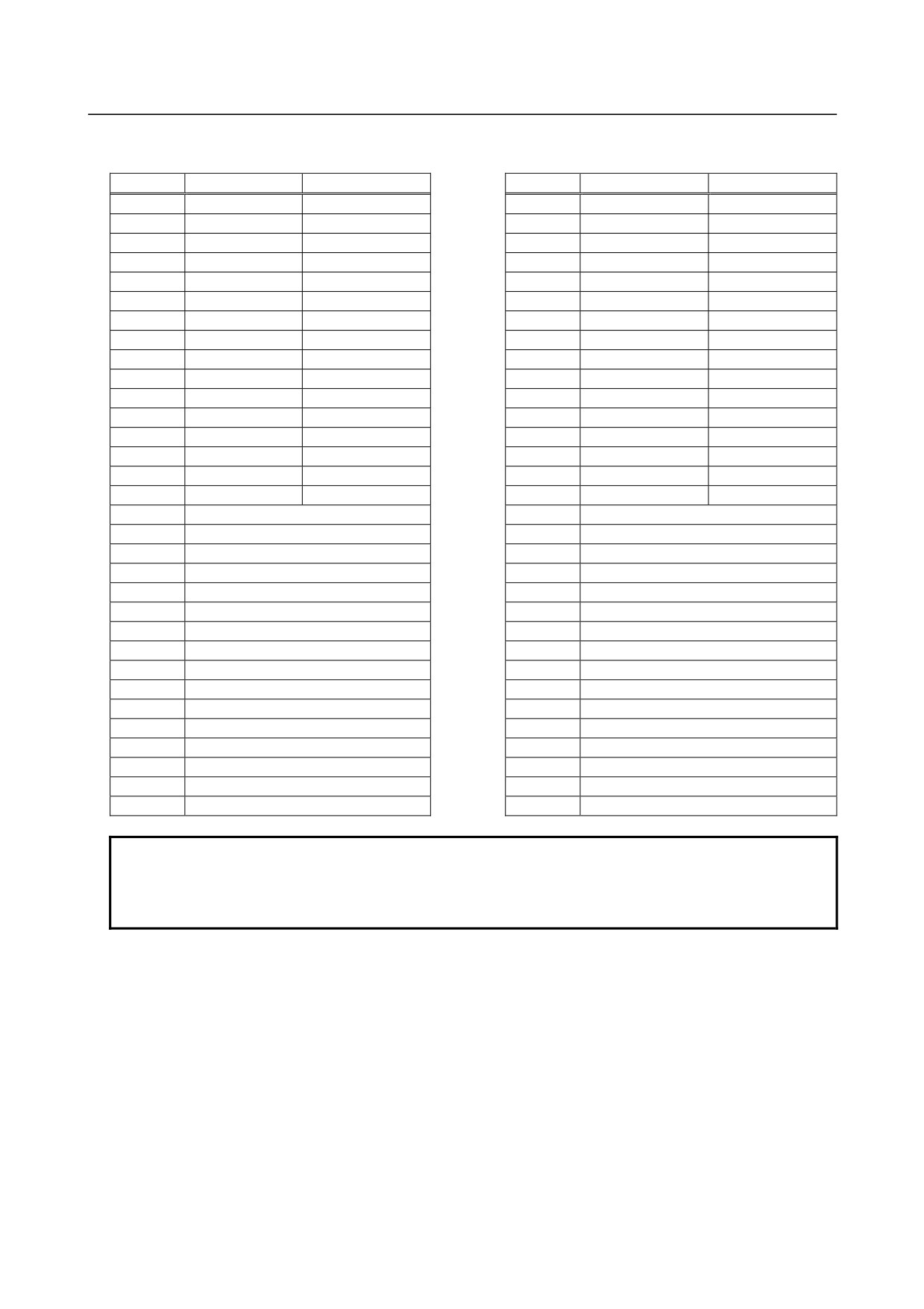
<Output>
Group α
Group α+1
Y
bit 7-4
bit 3-0
Y'
bit 7-4
bit 3-0
+0
DO #1A
Reserved
+0
DO #1B
Reserved
+1
DO #3A
DO #2A
+1
DO #3B
DO #2B
+2
DO #5A
DO #4A
+2
DO #5B
DO #4B
+3
DO #7A
DO #6A
+3
DO #7B
DO #6B
+4
DO #9A
DO #8A
+4
DO #9B
DO #8B
+5
DO #11A
DO #10A
+5
DO #11B
DO #10B
+6
DO #13A
DO #12A
+6
DO #13B
DO #12B
+7
DO #15A
DO #14A
+7
DO #15B
DO #14B
+8
DO #17A
DO #16A
+8
DO #17B
DO #16B
+9
DO #19A
DO #18A
+9
DO #19B
DO #18B
+10
DO #21A
DO #20A
+10
DO #21B
DO #20B
+11
DO #23A
DO #22A
+11
DO #23B
DO #22B
+12
DO #25A
DO #24A
+12
DO #25B
DO #24B
+13
DO #27A
DO #26A
+13
DO #27B
DO #26B
+14
DO #29A
DO #28A
+14
DO #29B
DO #28B
+15
DO #31A
DO #30A
+15
DO #31B
DO #30B
+16
Command flag
+16
Reserved
+17
Command code
+17
Reserved
+18
Command parameter (1)
+18
Command parameter (6)
+19
Command parameter (2)
+19
Command parameter (7)
+20
Command parameter (3)
+20
Command parameter (8)
+21
Command parameter (4)
+21
Command parameter (9)
+22
Command parameter (5)
+22
Reserved
+23
Reserved
+23
Reserved
+24
Reserved
+24
Reserved
+25
Reserved
+25
Reserved
+26
Reserved
+26
Reserved
+27
Reserved
+27
Reserved
+28
Reserved
+28
Reserved
+29
Reserved
+29
Reserved
+30
Reserved
+30
Reserved
+31
Reserved
+31
Reserved
NOTE
1 A number and letter after # represent an AS-i slave number.
2 To group α, the standard slave or an A slave of the A/B slaves is assigned.
To group α+1, a B slave of the A/B slaves is assigned.
- 328 -
B-64303EN/03
9.CONNECTION OF I/O Link SLAVE DEVICES
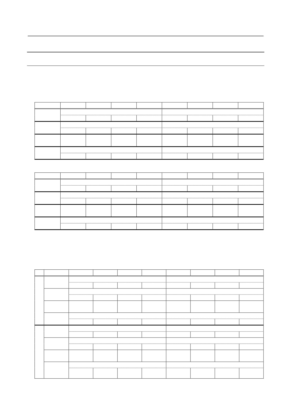
9.12.5 Details of I/O Link DI/DO
9.12.5.1 Input/output data area
For AS-i Ver. 2.0 (A03B-0817-C001)
Input signals are assigned to X+0 to X+15, and output signals are assigned to Y+0 to Y+15. Each bit set
to 1 represents the ON state, and each bit set to 0 represents the OFF state.
<Input>
Address
bit 7
bit 6
bit 5
bit 4
bit 3
bit 2
bit 1
bit 0
X+0
DI of slave address #1
Reserved
IN4
IN3
IN2
IN1
Reserved
Reserved
Reserved
Reserved
X+1
DI of slave address #3
DI of slave address #2
IN4
IN3
IN2
IN1
IN4
IN3
IN2
IN1
:
:
:
:
:
:
:
:
:
:
:
:
:
:
:
:
:
:
X+15
DI of slave address #31
DI of slave address #30
IN4
IN3
IN2
IN1
IN4
IN3
IN2
IN1
<Output>
Address
bit 7
bit 6
bit 5
bit 4
bit 3
bit 2
bit 1
bit 0
Y+0
DO of slave address #1
Reserved
OUT4
OUT3
OUT2
OUT1
Reserved
Reserved
Reserved
Reserved
Y+1
DO of slave address #3
DO of slave address #2
OUT4
OUT3
OUT2
OUT1
OUT4
OUT3
OUT2
OUT1
:
:
:
:
:
:
:
:
:
:
:
:
:
:
:
:
:
:
Y+15
DO of slave address #31
DO of slave address #30
OUT4
OUT3
OUT2
OUT1
OUT4
OUT3
OUT2
OUT1
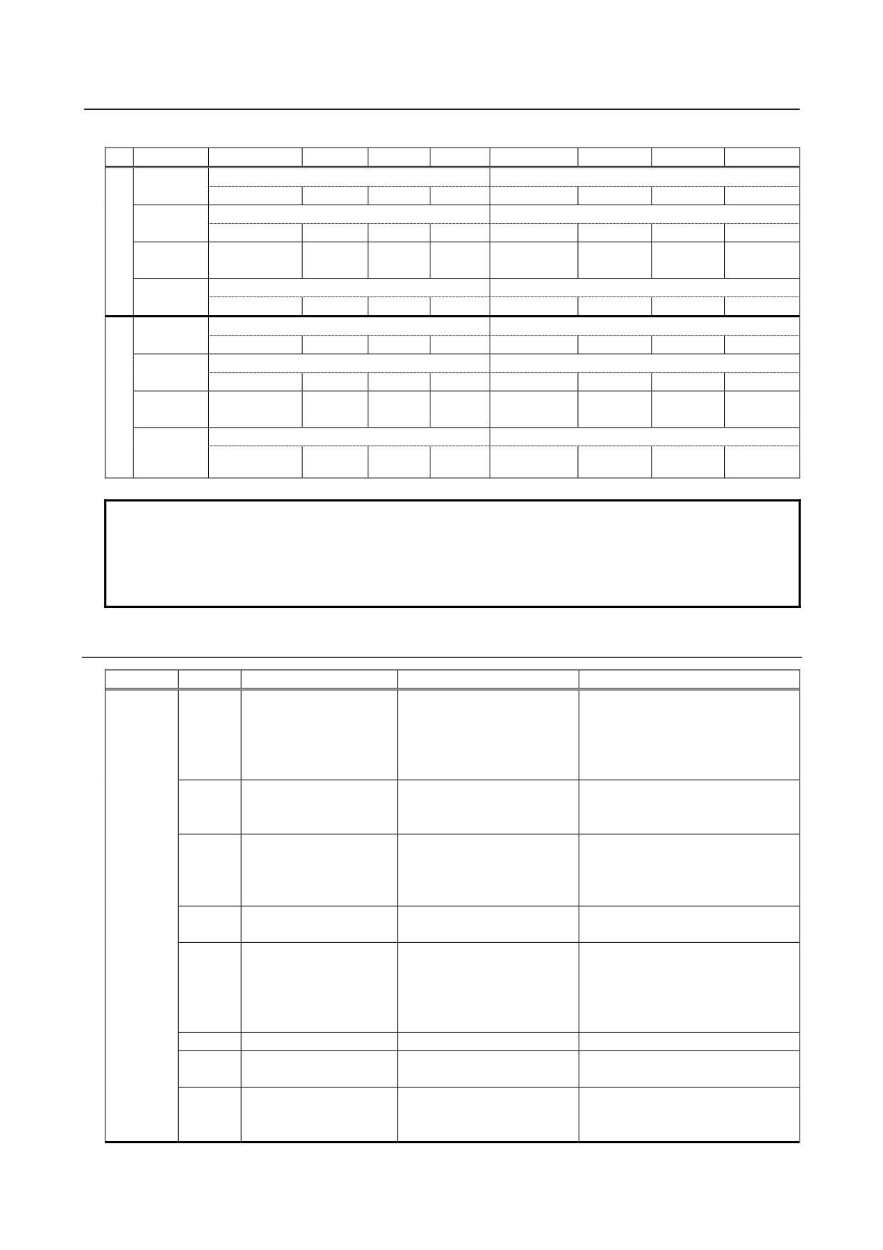
For AS-i Ver. 2.1 (A03B-0817-C002)
Input signals are assigned to X+0 to X+15 (group α) and X'+0 to X'+15 (group α+1), and output signals
are assigned to Y+0 to Y+15 (group α) and Y'+0 to Y'+15 (group α+1). Each bit set to 1 represents the
ON state, and each bit set to 0 represents the OFF state.
<Input>
Address
bit 7
bit 6
bit 5
bit 4
bit 3
bit 2
bit 1
bit 0
X+0
DI of slave address #1A
Reserved
G
IN4
IN3
IN2
IN1
Reserved
Reserved
Reserved
Reserved
r
X+1
DI of slave address #3A
DI of slave address #2A
o
IN4
IN3
IN2
IN1
IN4
IN3
IN2
IN1
u
:
:
:
:
:
:
:
:
:
p
:
:
:
:
:
:
:
:
:
X+15
DI of slave address #31A
DI of slave address #30A
α
IN4
IN3
IN2
IN1
IN4
IN3
IN2
IN1
G
X'+0
DI of slave address #1B
Reserved
r
IN4
IN3
IN2
IN1
Reserved
Reserved
Reserved
Reserved
o
X'+1
DI of slave address #3B
DI of slave address #2B
u
IN4
IN3
IN2
IN1
IN4
IN3
IN2
IN1
p
:
:
:
:
:
:
:
:
:
:
:
:
:
:
:
:
:
:
α
X'+15
DI of slave address #31B
DI of slave address #30B
+
IN4
IN3
IN2
IN1
IN4
IN3
IN2
IN1
1
- 329 -
9.CONNECTION OF I/O Link SLAVE DEVICES
B-64303EN/03
<Output>
Address
bit 7
bit 6
bit 5
bit 4
bit 3
bit 2
bit 1
bit 0
Y+0
DO of slave address #1A
Reserved
G
OUT4(NOTE)
OUT3
OUT2
OUT1
Reserved
Reserved
Reserved
Reserved
r
Y+1
DO of slave address #3A
DO of slave address #2A
o
OUT4(NOTE)
OUT3
OUT2
OUT1
OUT4(NOTE)
OUT3
OUT2
OUT1
u
:
:
:
:
:
:
:
:
:
p
:
:
:
:
:
:
:
:
:
X+15
DO of slave address #31A
DO of slave address #30A
α
OUT4(NOTE)
OUT3
OUT2
OUT1
OUT4(NOTE)
OUT3
OUT2
OUT1
G
Y'+0
DO of slave address #1B
Reserved
r
Reserved
OUT3
OUT2
OUT1
Reserved
Reserved
Reserved
Reserved
o
Y'+1
DO of slave address #3B
DO of slave address #2B
u
Reserved
OUT3
OUT2
OUT1
Reserved
OUT3
OUT2
OUT1
p
:
:
:
:
:
:
:
:
:
:
:
:
:
:
:
:
:
:
α
Y'+15
DO of slave address #31B
DO of slave address #30B
+
Reserved
OUT3
OUT2
OUT1
Reserved
OUT3
OUT2
OUT1
1
NOTE
A number and letter after # represent an AS-i slave number.
When the standard slave is used, DI/DO signals are assigned to group α (X+0 to
X+15 and Y+0 to Y+15).
When the A/B slave is used, OUT4 is reserved and cannot be used.
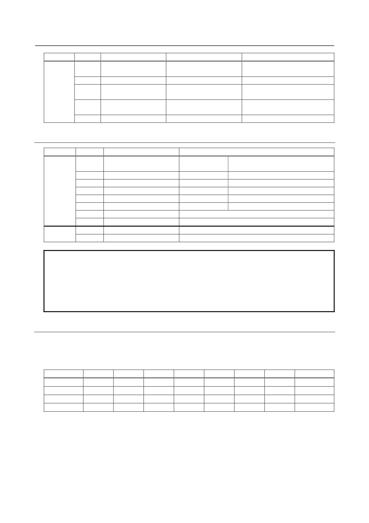
9.12.5.2
AS-i master status indication
Address
Bit
Item
Bit status
Condition for ON
X+16
0
Offline phase status
0: Not offline
When a command for setting the
1: Offline
offline status such as a command
for configuration registration is
executed or the AS-i power supply
is turned off
1
AS-i power supply
0: Normal
When the AS-i power supply
monitor
1: Decreased voltage or
voltage has decreased or the AS-i
OFF
power supply is turned off
2
Operation status
0: Initialization in progress
The normal operation mode is set
or start-up operation in
when AS-i communication is
progress
enabled.
1: Normal operation mode
3
Operation mode
0: Protection mode
When the configuration mode is
1: Configuration mode
set
4
Status of automatic
0: Disabled
Status where automatic
addressing
1: Enabled
addressing is enabled (when the
protection mode is set, automatic
addressing is enabled, and one
slave is detached)
5
Reserved
6
Connection of slave
0: Not connected
When a slave with address 0 is
with address 0
1: Connected
connected
7
Matching of current
0: Mismatch
When the registered configuration
configuration with
1: Match
matches detected slaves
registered configuration
- 330 -
B-64303EN/03
9.CONNECTION OF I/O Link SLAVE DEVICES
Address
Bit
Item
Bit status
Condition for ON
X+17
0
Offline operation status
0: Not offline
1: Offline
1
Reserved
2
EEPROM status in AS-i
0: Abnormal
When the EEPROM in the AS-i
master
1: Normal
master is normal
3
Automatic addressing
0: Disabled
When automatic addressing is
enable status
1: Enabled
enabled
4 to 7
Reserved
9.12.5.3
Board status
Address
Bit
Item
Bit status
X+18
0
AS-i data ready
0: DI/DO data is
1: DI/DO data is valid.
invalid.
1
Error status
0: Normal
1: Alarm
2
AS-i master error
0: Normal
1: AS-i master error
3
ROM error
0: Normal
1: ROM error
4
RAM error
0: Normal
1: RAM error
5
Watchdog alarm
0: Normal
1: CPU watchdog alarm
6
Reserved
7
Reserved
X+19
0 to 3
Software version
4 to 7
Hardware version
NOTE
To use the AS-i safely, be sure to monitor the AS-i status.
When using DI/DO data on the AS-i side, be sure to monitor the AS-i power
supply monitor information in Subsection 9.12.5.2, the AS-i data ready bit in
Subsection 9.12.5.3, and other error information items. If any of these
information items indicates an error or illegal status, the DI/DO data on the AS-i
converter side is also invalid. So, correct the system to maintain the safe status.
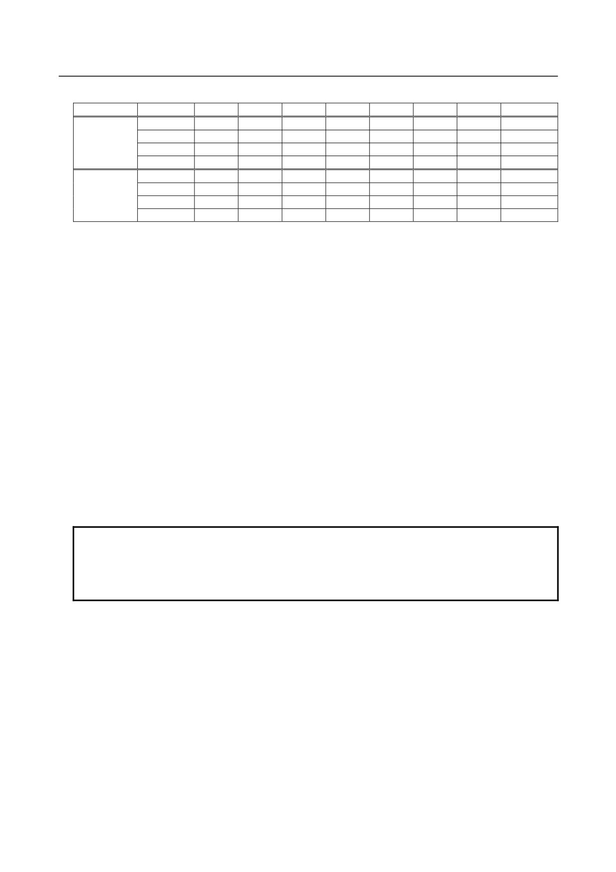
9.12.5.4 Slave list
From addresses X+20 to X+23 (plus X'+20 to X'+23 for Ver. 2.1), data is output in one of four different
modes, depending on the list output mode setting (bits 6 and 7 of Y+16 (Subsection 9.12.6.3)).
For AS-i Ver. 2.0 (A03B-0817-C001)
Address
bit 7
bit 6
bit 5
bit 4
bit 3
bit 2
bit 1
bit 0
X+20
#7
#6
#5
#4
#3
#2
#1
Reserved
X+21
#15
#14
#13
#12
#11
#10
#9
#8
X+22
#23
#22
#21
#20
#19
#18
#17
#16
X+23
#31
#30
#29
#28
#27
#26
#25
#24
- 331 -
9.CONNECTION OF I/O Link SLAVE DEVICES
B-64303EN/03
For AS-i Ver. 2.1 (A03B-0817-C002)
Group
Address
bit 7
bit 6
bit 5
bit 4
bit 3
bit 2
bit 1
bit 0
X+20
#7A
#6A
#5A
#4A
#3A
#2A
#1A
Reserved
α
X+21
#15A
#14A
#13A
#12A
#11A
#10A
#9A
#8A
X+22
#23A
#22A
#21A
#20A
#19A
#18A
#17A
#16A
X+23
#31A
#30A
#29A
#28A
#27A
#26A
#25A
#24A
X'+20
#7B
#6B
#5B
#4B
#3B
#2B
#1B
Reserved
α+1
X'+21
#15B
#14B
#13B
#12B
#11B
#10B
#9B
#8B
X'+22
#23B
#22B
#21B
#20B
#19B
#18B
#17B
#16B
X'+23
#31B
#30B
#29B
#28B
#27B
#26B
#25B
#24B
Mode 0: Discrepancy between LPS (list of configured slaves) and LES (list of detected slaves)
0: There is no discrepancy between LPS and LES.
1: There is a discrepancy between LPS and LES.
Mode 1: Contents of LES (list of detected slaves)
0: Slaves not connected
1: Slaves currently connected
Mode 2: Contents of LAS (list of active slaves)
0: Slaves not active
1: Slaves currently active
Mode 3: Contents of LPS (list of configured slaves)
0: Slaves not configured
1: Slaves configured
Check LES (mode 1) to know which slave is connected.
Check LPS (mode 2) to know which slave is configured.
Set mode 0 in normal operation. If a configuration mismatch error occurs during operation in the
protection mode, a mismatching slave can be identified by the discrepancy between LPS and LES (mode
0).
NOTE
If the list output mode is switched, up to about 3 seconds may be required until
an output change actually takes place after the mode switching. When reading
with a ladder, be sure to check the list output mode in status information
beforehand.
- 332 -
B-64303EN/03
9.CONNECTION OF I/O Link SLAVE DEVICES
9.12.6 Command Execution by a Ladder Program
A ladder program can read or write the parameter of an AS-i slave unit, can change addresses, and can
read the I/O configuration and ID code.
9.12.6.1 Types of commands executable by a ladder program
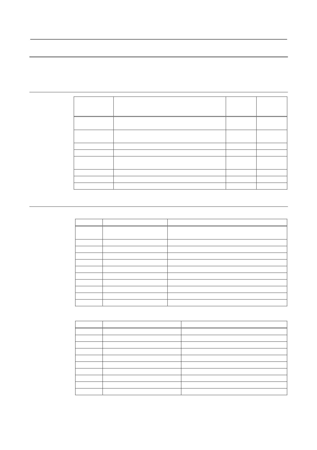
Command code
Description
Parameter
Response
(HEX)
byte length
data byte
length
0AH
Writes the parameter of a particular slave to the
2
0
EEPROM.
0BH
Reads the parameter of a particular slave from the
1
1
EEPROM.
0CH
Writes a parameter to a particular slave.
2
1
0DH
Reads the parameter of a particular slave.
1
1
12H
Reads the I/O configuration and ID code of a
1
2
particular slave.
17H
Changes the address of a particular slave.
2
0
For Ver. 2.1 only
29H
Reads the analog input data of a particular slave.
1
8
For Ver. 2.1 only
2AH
Writes analog output data to a particular slave.
9
0
9.12.6.2 Command interface with a ladder program
DO (PMC → AS-i converter)
Address
Name
Description
Y+16
Command flag
Command execution request flag, list output setting
mode
Y+17
Command code
Command code
Y+18
Command parameter 1
When the command has a parameter
Y+19
Command parameter 2
Same as above
Y+20
Command parameter 3
Same as above
Y+21
Command parameter 4
Same as above
For Ver. 2.1 only
Y+22
Command parameter 5
Same as above
For Ver. 2.1 only
Y'+18
Command parameter 6
Same as above
For Ver. 2.1 only
Y'+19
Command parameter 7
Same as above
For Ver. 2.1 only
Y'+20
Command parameter 8
Same as above
For Ver. 2.1 only
Y'+21
Command parameter 9
Same as above
DI (AS-i converter → PMC)
Address
Name
Description
X+24
Command status
End flag, list output status
X+25
Command error status
Error code of the executed command
X+26
Command response data 1
When the command has response data
X+27
Command response data 2
Same as above
X+28
Command response data 3
Same as above
X+29
Command response data 4
Same as above
For Ver. 2.1 only
X'+26
Command response data 5
Same as above
For Ver. 2.1 only
X'+27
Command response data 6
Same as above
For Ver. 2.1 only
X'+28
Command response data 7
Same as above
For Ver. 2.1 only
X'+29
Command response data 8
Same as above
- 333 -
9.CONNECTION OF I/O Link SLAVE DEVICES
B-64303EN/03
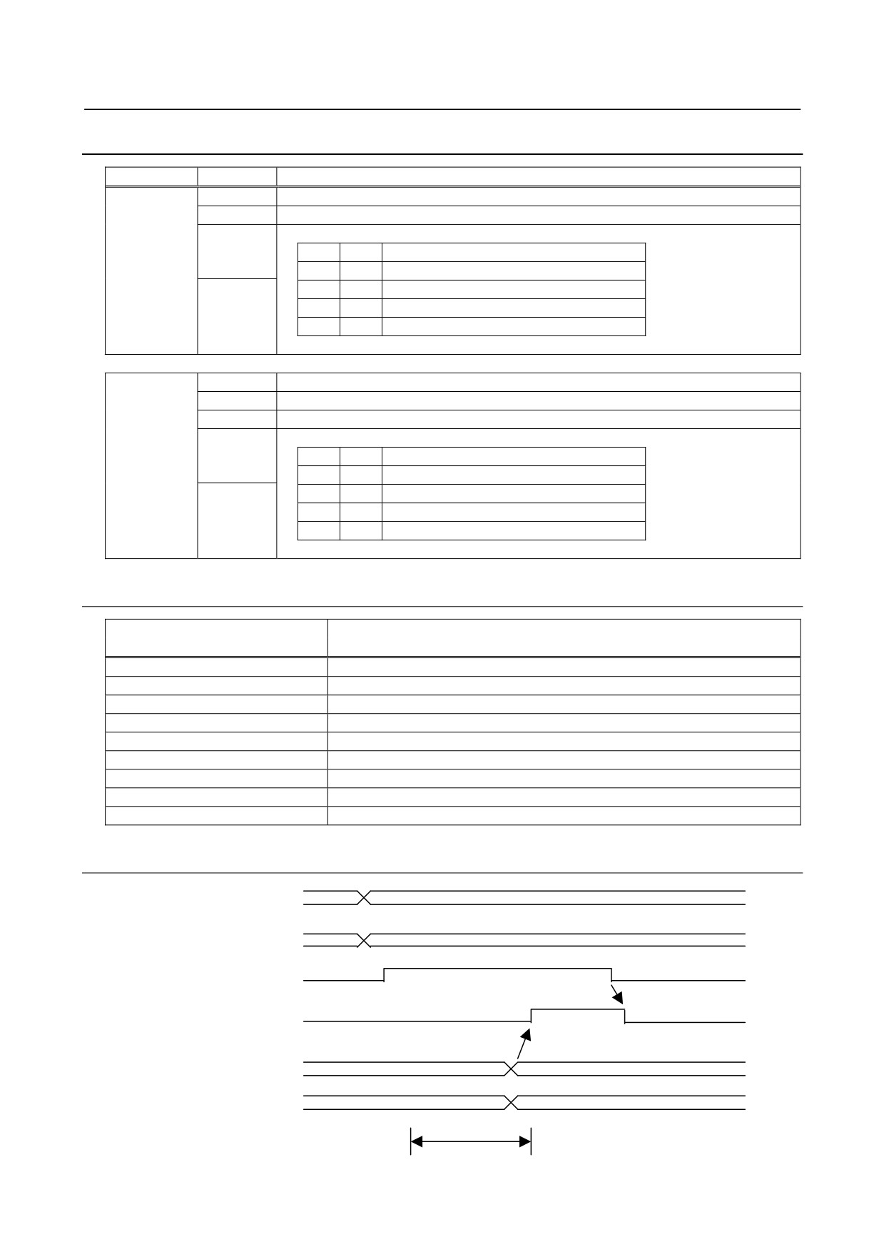
9.12.6.3 Details of command flags and status
Address
Bit
Description
Y+16
0
Request flag
1: Requested
1 to 5
Reserved
6
List output request mode
Bit 7
Bit 6
Description
0
0
Discrepancy between LPS and LES
7
0
1
LES (list of detected slaves)
1
0
LAS (list of active slaves)
1
1
LPS (list of configured slaves)
X+24
0
End flag
1: End of command
1
Error flag
1: Command error (For details, see Subsection 9.12.6.4, "Error codes".)
2 to 5
Reserved
6
List output mode
Bit 7
Bit 6
Description
0
0
Discrepancy between LPS and LES
7
0
1
LES (list of detected slaves)
1
0
LAS (list of active slaves)
1
1
LPS (list of configured slaves)
9.12.6.4 Error codes
Error code (HEX)
Description
00H
Normal command termination
02H
Slave address error
03H
The specified slave is not active (not listed in LAS).
04H
A slave with address 0 exists.
05H
AS-i communication error
06H
EEPROM error
07H
Command or parameter error
08H
In executable command
09H
Command error (command code error)
9.12.6.5 Command handshake sequence
Command code
Command parameter
<1>
Request flag
<3>
<4>
End flag
Error status
Response data
Command execution
<2>
- 334 -
B-64303EN/03
9.CONNECTION OF I/O Link SLAVE DEVICES
<1> PMC side: Command code is written after checking that both of the request flag and end flag are
OFF. If the command has parameter data, the parameter data is written simultaneously. Next, the
request flag is set to ON. Within the same scan period, command code may be written and the
request flag may be set to ON.
<2> Converter side: When the request flag is set, command code is read then the command is executed.
Upon completion of command execution, error status and response data are transferred then the end
flag is set to ON.
<3> PMC side: The end flag set to ON is awaited. When the end flag is set to ON, error status is read. In
the case of normal termination with response data, the response data is read. Upon completion of
processing, the end flag is set to OFF.
<4> Converter side: When the request flag is set to OFF, the end flag is set to OFF.
NOTE
The operations of <2> and <4> are performed by the AS-i converter.
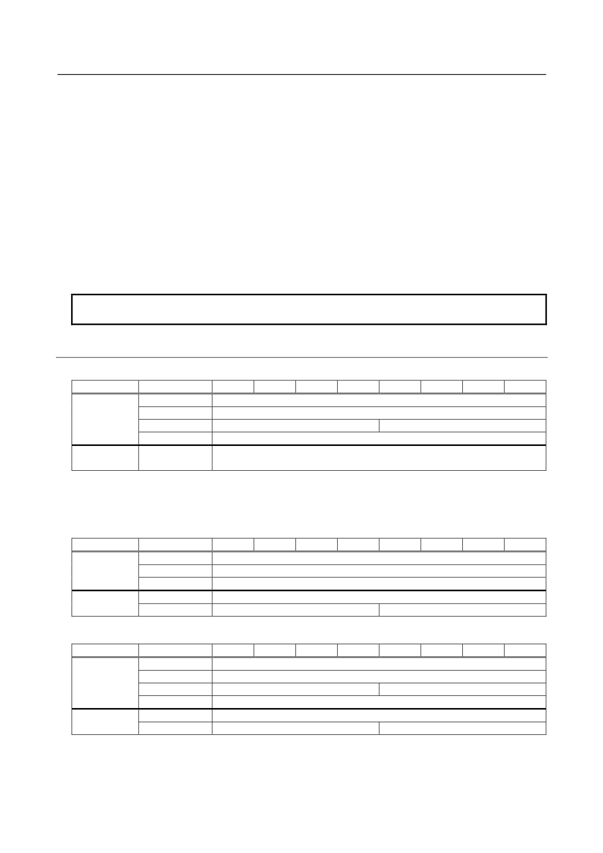
9.12.6.6 Details of commands
(1) Writing the parameter of a particular slave to the EEPROM of the AS-i master
Address
bit 7
bit 6
bit 5
bit 4
bit 3
bit 2
bit 1
bit 0
Execution
Y+17
0AH
data
Y+18
Slave address (01H to 1FH, 21H to 3FH)(NOTE)
Y+19
0
Parameter value
Y+20 to Y+21
Not set
Response
X+25
Error code
data
A parameter value written to the EEPROM of the AS-i master is not transferred to slaves at the time of
command execution but is transferred to each slave when the power is turned on next time.
(2) Reading the parameter of a particular slave from the EEPROM of the AS-i
master
Address
bit 7
bit 6
bit 5
bit 4
bit 3
bit 2
bit 1
bit 0
Execution
Y+17
0BH
data
Y+18
Slave address (01H to 1FH, 21H to 3FH)(NOTE)
Y+19 to Y+21
Not set
Response
X+25
Error code
data
X+26
0
Parameter value
(3) Writing a parameter to a particular slave
Address
bit 7
bit 6
bit 5
bit 4
bit 3
bit 2
bit 1
bit 0
Execution
Y+17
0CH
data
Y+18
Slave address (01H to 1FH, 21H to 3FH)(NOTE)
Y+19
0
Parameter value
Y+20 to Y+21
Not set
Response
X+25
Error code
data
X+26
0
Parameter echo
A parameter value is transferred to a slave at the time of command execution. However, the parameter
value is not stored in the EEPROM of the AS-i master, so that the parameter value is lost when the power
is turned off.
- 335 -
9.CONNECTION OF I/O Link SLAVE DEVICES
B-64303EN/03
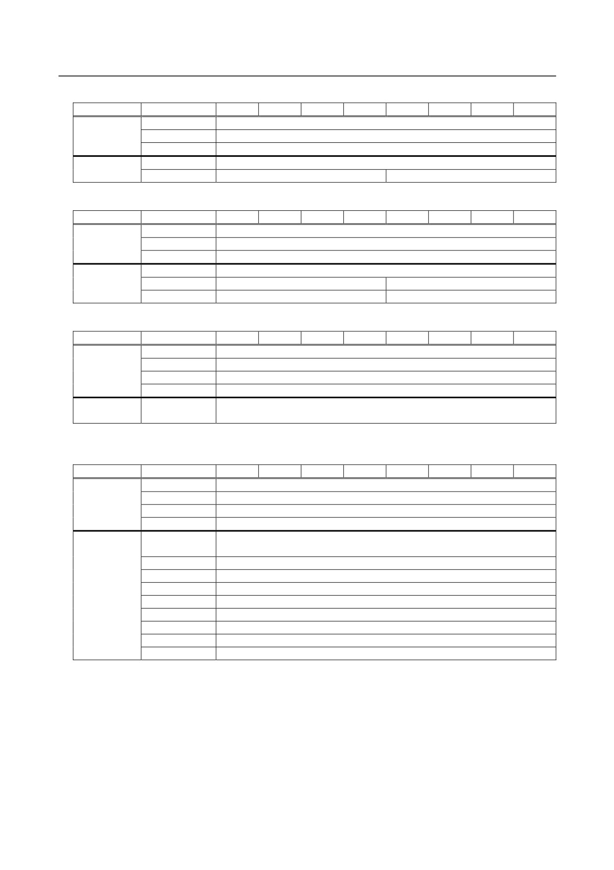
(4) Reading the parameter of a particular slave
Address
bit 7
bit 6
bit 5
bit 4
bit 3
bit 2
bit 1
bit 0
Execution
Y+17
0DH
data
Y+18
Slave address (01H to 1FH, 21H to 3FH)(NOTE)
Y+19 to Y+21
Not set
Response
X+25
Error code
data
X+26
0
Parameter value
(5) Reading the I/O configuration and ID code of a particular slave
Address
bit 7
bit 6
bit 5
bit 4
bit 3
bit 2
bit 1
bit 0
Execution
Y+17
12H
data
Y+18
Slave address (01H to 1FH, 21H to 3FH)(NOTE)
Y+19 to Y+21
Not set
Response
X+25
Error code
data
X+26
0
ID code
X+27
0
I/O configuration
(6) Changing the address of a particular slave
Address
bit 7
bit 6
bit 5
bit 4
bit 3
bit 2
bit 1
bit 0
Execution
Y+17
17H
data
Y+18
Slave address before change (01H to 1FH, 21H to 3FH)(NOTE)
Y+19
Slave address after change (01H to 1FH, 21H to 3FH)(NOTE)
Y+20 to Y+21
Not set
Response
X+25
Error code
data
This command cannot be executed when a slave with address 0 is connected.
(7) Reading the analog input data of a particular slave
Address
bit 7
bit 6
bit 5
bit 4
bit 3
bit 2
bit 1
bit 0
Execution
Y+17
29H
data
Y+18
Slave address (01H to 1FH)(NOTE)
Y+19 to Y+21
Not set
Y'+18 to Y'+21
Not set
Response
X+25
Error code
data
X+26
Channel 1 input data (higher byte)
X+27
Channel 1 input data (lower byte)
X+28
Channel 2 input data (higher byte)
X+29
Channel 2 input data (lower byte)
X'+26
Channel 3 input data (higher byte)
X'+27
Channel 3 input data (lower byte)
X'+28
Channel 4 input data (higher byte)
X'+29
Channel 4 input data (lower byte)
This command can be executed only with an AS-i converter of Ver. 2.1.
- 336 -
B-64303EN/03
9.CONNECTION OF I/O Link SLAVE DEVICES
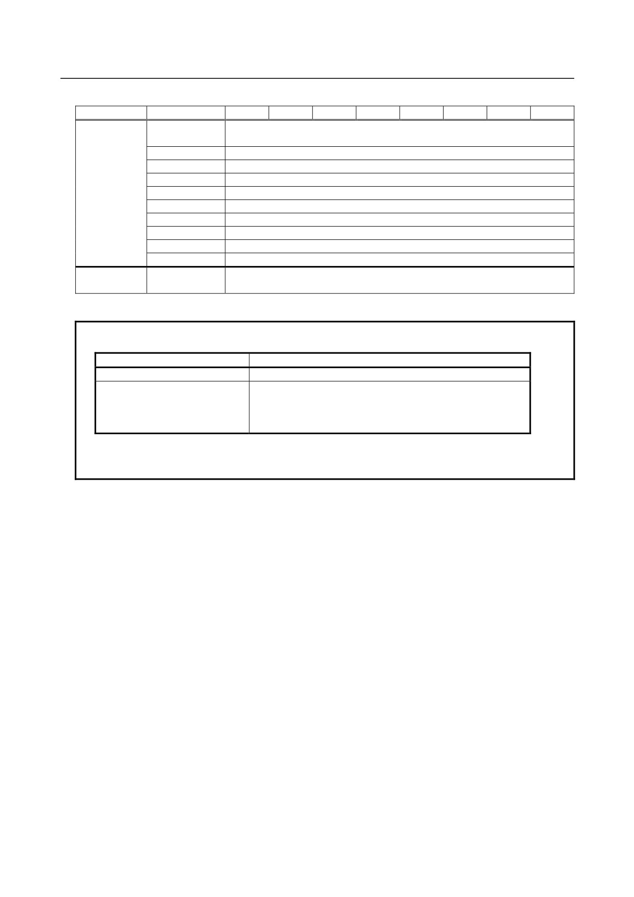
(8) Writing analog output data to a particular slave
Address
bit 7
bit 6
bit 5
bit 4
bit 3
bit 2
bit 1
bit 0
Execution
Y+17
2AH
data
Y+18
Slave address (01H to 1FH)(NOTE)
Y+19
Channel 1 output data (higher byte)
Y+20
Channel 1 output data (lower byte)
Y+21
Channel 2 output data (higher byte)
Y+22
Channel 2 output data (lower byte)
Y'+18
Channel 3 output data (higher byte)
Y'+19
Channel 3 output data (lower byte)
Y'+20
Channel 4 output data (higher byte)
Y'+21
Channel 4 output data (lower byte)
Response
X+25
Error code
data
This command can be executed only with an AS-i converter of Ver. 2.1.
NOTE
Input an AS-i slave address number as follows:
Slave type
Address input method
Standard slave or A slave
Input an address number directly in hexadecimal (01H to 1FH).
B slave
Input an address number added to 32 (20hex) in hexadecimal.
Example) When the address is 10B
10 + 32 → 42 (Input 2Ahex.)
An analog slave is a standard slave to which address distinction between A and
B is not applicable. So, input an address number directly in hexadecimal (01H to
1FH).
- 337 -
9.CONNECTION OF I/O Link SLAVE DEVICES
B-64303EN/03
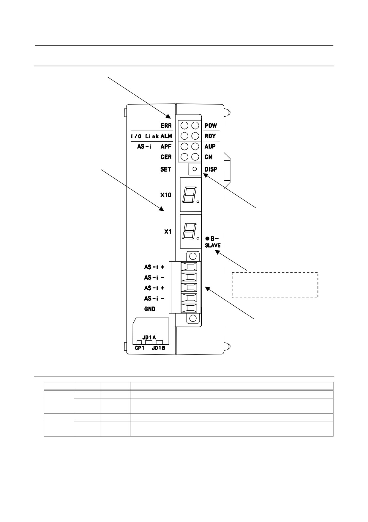
9.12.7 LED Status Indication and Setting Switch Operation
(1)LED
(2) 7-sgment LED
(3) Setting/display switch
Note) This indication is provided
only on an AS-i converter
of Ver. 2.1.
(4) AS-i terminal block
9.12.7.1 LED indication
Name
Color
Description
Overall
POW
Green
Indicates that the power to the AS-i converter is on.
ERR
Red
Turned on when there is an error. (For error details, check the other LEDs,
7-segment LEDs, and status on the I/O Link.)
I/O Link
RDY
Green
Turned on when the I/O Link is ready for communication.
ALM
Red
Indicates that an alarm is issued on the I/O Link. (For error details, check the
7-segment LEDs.)
- 338 -
B-64303EN/03
9.CONNECTION OF I/O Link SLAVE DEVICES
Name
Color
Description
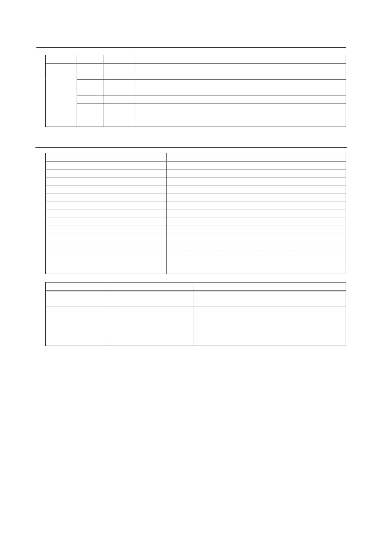
AS-i
AUP
Green
Turned on when the operation mode is the protection mode and automatic
addressing is enabled.
CM
Green
Turned on when the operation mode is the configuration mode and turned off
when the operation mode is the protection mode.
APF
Red
Turned on when the voltage of the AS-i power supply is low.
CER
Red
Turned on when there is a discrepancy between the configured slaves and the
currently connected slaves (when there is a discrepancy in LPS, ID code, or I/O
configuration).
9.12.7.2
7-segment LED indication
LED indication
Description
No indication
Normal operation
E0
AS-i master error
E1
AS-i master EEPROM error
E2
ROM error
E3
RAM error
E5
Command execution error, SET switch execution error
E6
I/O Link slave watchdog alarm
E7
I/O Link RAM error
E8
Watchdog alarm 1
E9 or "." (dot) of X10
Watchdog alarm 2
00 to 31
Slave address indication (See the table below and the next page.)
"." (dot) of X1
Turned on when a B slave address is indicated.
88
Initialization in progress, mode switching in progress, AS-i power
supply voltage decrease
Operation mode
In normal operation
When the setting switch (DISP) is pressed
Configuration mode
No display
Displays all connected slaves at intervals of about one
second (display of LES).
Protection mode
The smallest slave address
Displays all configuration-mismatching slaves at intervals
among those of the
of about one second (displays a list of discrepancies
configuration-mismatching
between LPS and LES).
slaves is displayed.
* No data is displayed when there is no
configuration-mismatching slave.
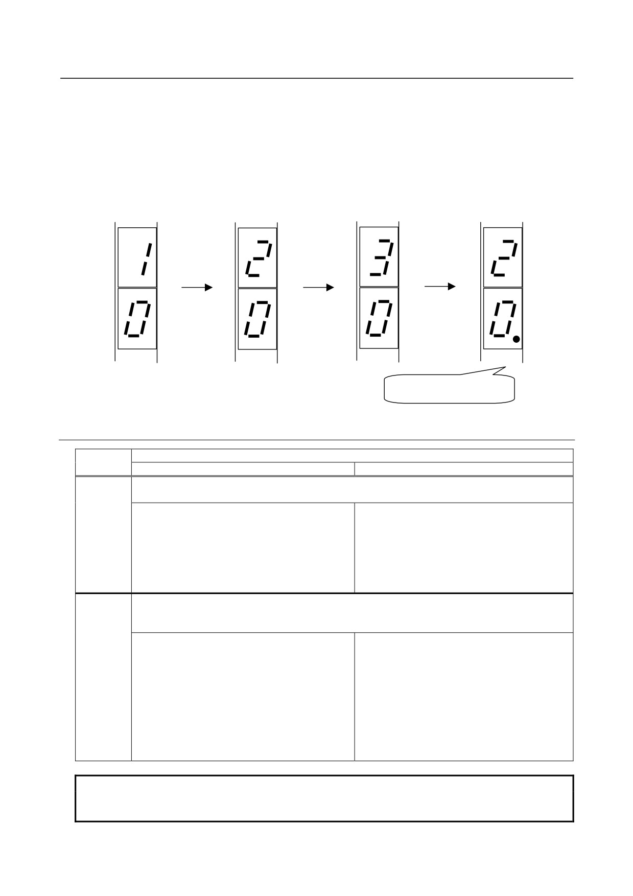
Order of slave number display with Ver. 2.1
Slave numbers are displayed in the order from standard slaves or A slaves (with "." of X1 turned off) to B
slaves (with "." of X1 turned on).
- 339 -
9.CONNECTION OF I/O Link SLAVE DEVICES
B-64303EN/03
(Example)
When the following slaves are connected, the slave numbers are displayed in the order shown below:
Address #10
Standard slave
Address #20A
A/B slave
Address #20B
A/B slave
Address #30
Standard slave
Address #10
Address #20A
Address #30
Address #20B
Standard slave
A/B slave
Standard slave
A/B slave
X10
X10
X10
X10
X1
X1
X1
X1
●B-
●B-
●B-
●B-
SLAVE
SLAVE
SLAVE
SLAVE
"." (dot) of X1 is turned on.
9.12.7.3
Setting/display switch
Switch
Operation mode
Configuration mode
Protection mode
DISP
The addresses of slaves are displayed.
No additional input is accepted until the addresses of all slaves are displayed.
The addresses of all slaves are displayed at
The addresses of all configuration-mismatching
intervals of about 1 second. (LES is displayed).
slaves are displayed at intervals of about 1
second. (A list of discrepancies between LPS
and LES is displayed.)
No data is displayed when there is no
configuration-mismatching slave.
SET
The operation mode is switched.
Holding down this switch continually does not switch the mode successively. Be sure to turn off this
switch for 1 second or more before switching to the next mode.
Pressing this switch for 5 seconds or more
Pressing this switch for 5 seconds or more
registers the current slave configuration (LPS, ID
changes the mode to the configuration mode.
code, I/O configuration, and parameters), enables
automatic addressing, and switches the mode to
the protection mode.
Pressing this switch for less than 5 seconds
Pressing this switch for less than 5 seconds
does not change the mode.
changes the mode to the protection mode. In this
case, however, the configuration is not registered
and automatic addressing is not enabled.
NOTE
If a slave with address 0 is connected, the configuration cannot be registered
and the mode is not switched to the protection mode. Alarm E5 is indicated.
- 340 -
B-64303EN/03
9.CONNECTION OF I/O Link SLAVE DEVICES
9.12.7.4 Error processing
Check the error state with the LED indication and the status signals on the I/O Link.
Alarm or
LED indication
Status signals on I/O Link
Cause and corrective action
warning
LED
7-segment
ERR
AS-i
Others
LED
data
X+18
ready
bit 1
X+18
bit 0
Normal
-
Turned off
0
1
-
-
operation
Configuration
CER
(NOTE)
0
1
X+16
There are discrepancies between the
mismatch
turned on
bit 7=0
registered configuration and the current slave
configuration. Pressing DISP in the protection
mode displays
the
addresses
of
configuration-mismatching slaves.
The cause may be a slave unit failure, AS-i
cable disconnection, or AS-i communication
error due to noise.
Initialization in
-
88
0
0
X+16
or X+17
progress, or
bit 0=1
bit 0=1
mode switching
in progress
AS-i power
APF
88
1
0
X+16
Check if the AS-i power supply is normal and
supply voltage
turned on
bit 1=1
check also if the cable from the AS-i power
decrease
supply is normal.
This error is automatically recovered when the
AS-i power supply becomes normal.
AS-i master
ERR
E1
1
0
X+17
Restart the power supply. The registered
EEPROM
turned on
bit 2=0
configuration may have been destroyed. So,
error
register the configuration again (according to
NOTE below).
If this error still occurs, replace the AS-i
converter.
AS-i master
ERR
E0
1
0
X+18
Restart the power supply. If this error still
error
turned on
bit 2=1
occurs, replace the AS-i converter.
ROM error
ERR
E2
1
0
X+18
Replace the AS-i converter.
turned on
bit 3=1
RAM error
ERR
E3
1
0
X+18
Replace the AS-i converter.
turned on
bit 4=1
Watchdog 1
ERR
E8
1
0
X+18
Replace the AS-i converter.
turned on
bit 5=1
Watchdog 2
ERR
E9 or
1
0
-
An I/O Link system alarm is issued on the NC
turned on
"." of X10
side.
Replace the AS-i converter.
I/O Link
ERR
E6
-
-
-
An I/O Link system alarm is issued on the NC
slave
turned on
side.
watchdog
The power to another device connected to the
I/O Link may be turned off, or the I/O Link cable
may be disconnected.
An I/O Link communication error may have
occurred due to noise.
I/O Link
ERR
E7
-
-
-
An I/O Link system alarm is issued on the NC
RAM error
turned on
side.
Replace the AS-i converter.
- 341 -
9.CONNECTION OF I/O Link SLAVE DEVICES
B-64303EN/03
NOTE
1
In the protection mode, the smallest one of the addresses of the
configuration-mismatching slaves is displayed. No data is displayed in the
configuration mode.
2
Use a ladder program to detect and display an AS-i converter error.
3
When an AS-i converter error occurs, both of the DO signals and DI signals are
turned off.
4
When AS-i communication fails, a watchdog alarm is issued on the slave unit
side. When a slave watchdog alarm is issued, the behavior of DO signals is
determined by the type of slave unit and parameter setting. For details, refer to
the specifications of the slave unit.
5
Corrective action for an AS-i master EEPROM error
When the 7-segment LEDs indicate E1, the registered configuration may have
been destroyed. So, register the configuration again according to the procedure
below.
Turn off the power.
Turn on the power again while setting the switch to SET.
The 7-segment LEDs indicate "E1". (Keep the switch set to SET.)
Keep the switch set to SET until the LED ”CM” switches from off to on or vice versa.
(This operation may require 5 seconds or more.)
Release the switch. Next, turn off the power then turn on the power again to restart the system.
The register configuration is recovered if the 7-segment LEDs do not indicate "E1". (If the LED ”CM” is
turned on, protect the registered configuration in preparation for subsequent operation. Keep the switch
set to SET until the LED "CM" is turned off. This operation may require 5 seconds or more.)
If the 7-segment LEDs still indicate "E1" after the operation above,
replace the AS-i converter.
* Note that if "E1" is indicated, the CNC may not be started.
AS-i converters with this function were shipped in June, 2005 or later.
The corrective action mentioned above cannot be applied to those AS-i
converters that were shipped earlier. In this case, replace the AS-i converter if an
EEPROM error occurs.
- 342 -
B-64303EN/03
9.CONNECTION OF I/O Link SLAVE DEVICES
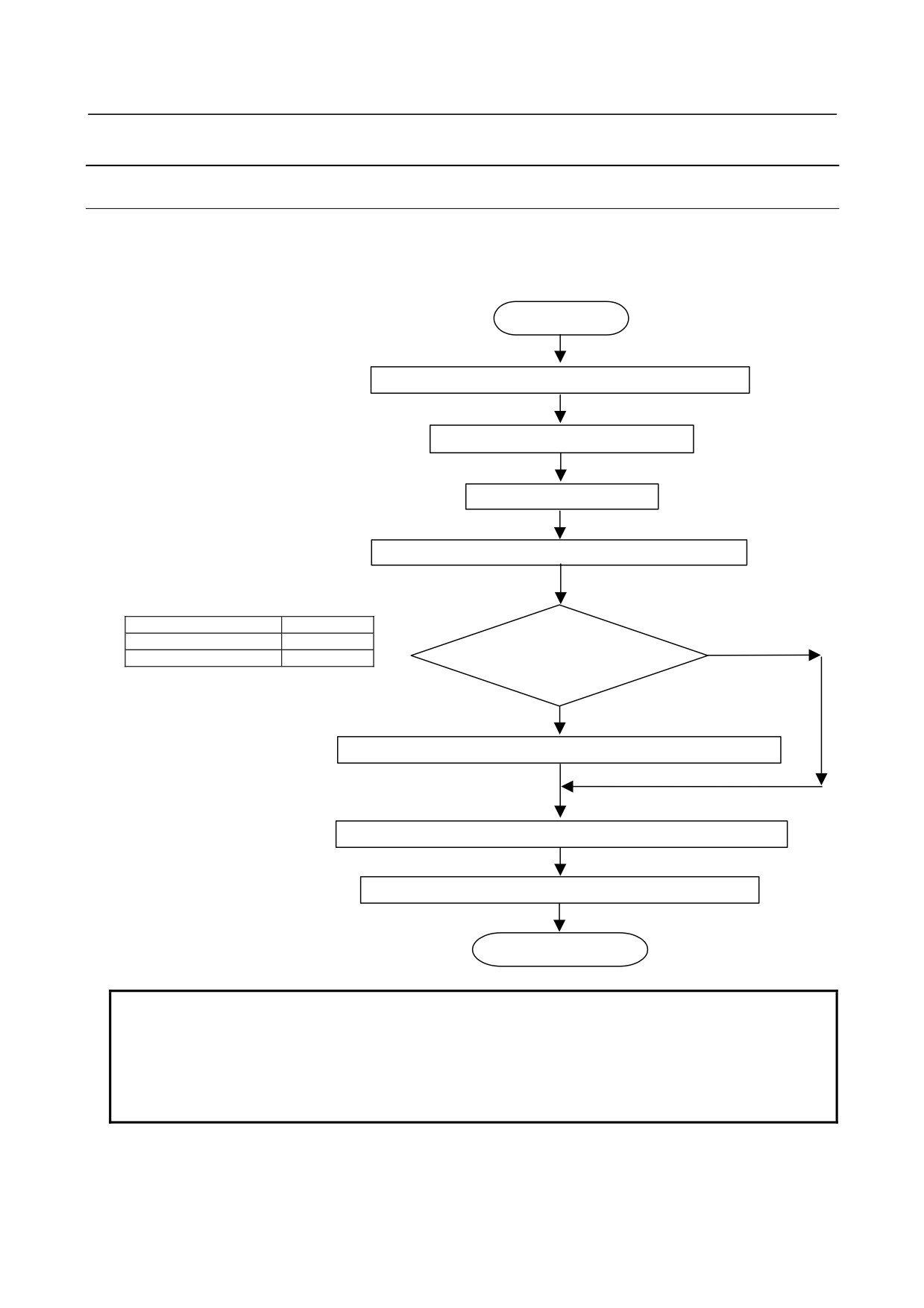
9.12.8 How to Use the I/O Link-AS-i Converter
9.12.8.1 Installation
The operation below can be performed even when the I/O Link is not connected (for example, when the
power to the CNC is not turned on with only the power to the AS-i converter and AS-i power supply
turned on or when the I/O Link cable is not connected).
Start
Install AS-i converter, AS-i slaves, and AS-i power supply.
Set addresses of AS-i slaves.
Connect AS-i cable.
Turn on power to AS-i converter and AS-i power supply.
Mode
LED "CM"
Configuration
Turned on
YES
Protection
Turned off
Configuration mode?
NO
Press SET switch for 5 seconds or more to set configuration mode.
Press DISP switch to check currently connected slave number.
Press SET switch for 5 seconds or more to set protection mode.
End of installation
NOTE
1 When the operation mode is switched to the protection mode, the slave
configuration is registered and automatic addressing is enabled.
2 The operation mode remains unchanged, regardless of whether the power to the
AS-i converter is turned on or off. To switch the operation mode, use the SET
switch.
- 343 -
9.CONNECTION OF I/O Link SLAVE DEVICES
B-64303EN/03
9.12.8.2 Normal operation
(1) Operation mode
The protection mode is used in normal operation.
In this mode, a configuration mismatch error occurs and CER is turned on if communication with an AS-i
slave unit is disabled for a cause such as a disconnected cable, AS-i communication error, and slave unit
failure.
(2) Alarm monitor
Monitor the alarm signal (alarm issued by bit 1 of X+18 set to 1) on the I/O Link with a CNC ladder
program and ensure that a PMC alarm is issued to notify maintenance staff if an error occurs.
Check the cause of an alarm with the LED indications and the status signals (X+16 to X+18) on the I/O
Link then take a proper corrective action.
(3) Configuration mismatch
A configuration mismatch means that the current slave configuration differs from the slave configuration
registered when the operation mode is switched from the configuration mode to the protection mode.
Pressing the DISP switch in the protection mode when CER is turned on displays all
configuration-mismatching slave numbers sequentially.
Monitor for this configuration-mismatching error (bit 7 of X+16) with a CNC ladder program and ensure
that a PMC alarm is issued to notify maintenance staff if this error occurs. To take a proper corrective
action, maintenance staff can identify the slave number in question by pressing the DISP switch as
mentioned earlier.
With a ladder program, configuration-mismatching slave numbers can be displayed on the display unit of
the CNC.
(4) Causes of configuration mismatch and corrective action
A configuration mismatch can occur for a cause such as a disconnected cable, communication error, and
AS-i slave unit failure.
a) Disconnected cable
The cause may be identified as a disconnected cable if all slaves after a particular slave are
configuration-mismatching slaves.
b) Communication error
A temporary communication error may be recovered by restarting the operation. In this case, however,
check whether a large noise source is located nearby and whether all connections are made normally.
c) Slave unit failure
If normal operation cannot be resumed after a restart, the cause may be a slave unit hardware failure.
When only one slave unit is to be replaced, an address number can be automatically set with the
automatic addressing function.
When multiple slave units are to be replaced, addresses for the slave units can be set on a one-by-one
basis with the automatic addressing function or addresses for all slaves can be set beforehand using the
addressing device.
d) No address setting
An AS-i slave with address "0" is connected.
(5) AS-i data ready flag (X+18: Bit 0)
Before reading DI signals with a ladder, check that the AS-i data ready flag is set to 1. If the flag is set to
0, do not use DI signals.
- 344 -
B-64303EN/03
9.CONNECTION OF I/O Link SLAVE DEVICES
9.12.9 Others
9.12.9.1 CE marking
The AS-i converter has CE marking certification.
Note, however, that because of its conformance to the AS-i EN standard (EN50295), the AS-i converter
has not undergone surge test.
9.12.9.2 Fuse
The AS-i converter has a built-in fuse. If the fuse blows, replace the fuse after correcting the cause.
Blown fuse indication
Rating
Ordering information
POW is off.
1 A
A03B-0815-K001
A fuse is installed on the printed circuit board inside the unit.
- 345 -
10.STOP AND EMERGENCY STOP
B-64303EN/03
10 STOP AND EMERGENCY STOP
10.1 STOP MODES
There are the following stop modes:
1.
Stop by shutting off the motor power
2.
Controlled stop without shutting off the motor power
3.
Stop by shutting off the motor power after a controlled stop
A controlled stop is the quickest. However, a stop may be made by immediately shutting off the motor
power for safety reasons.
WARNING
Pressing the RESET key stops the running program. As a result, the servo axis
stops and the spindle axis remains rotating without changing the speed. The
RESET key may not function due to an MDI failure or the like, so, for safety, use
the emergency stop button instead of the RESET key to stop the motor safely.
When a failure of the CNC, machine contact, or connection is also assumed,
further safety actions must be taken.
10.2 SHUTTING OFF THE MOTOR POWER
The motor power may be shut off through an IGBT (transistor) or an electromechanical scheme that
controls mechanical contacts. When an αi series amplifier is used, the motor power is shut off by an
IGBT (transistor) based on the CNC alarm state (or Ladder program). To shut off the motor power
through an electromechanical scheme, a line contactor must be installed on the power input line in the
power supply module, thereby providing a direct contactor shut-off route.
(See Fig. 10.5 in Section 10.5,
"EMERGENCY STOP SIGNAL.")
The power supply module provides MCC control signals (MCCOFF3 and MCCOFF4) for controlling the
contactor. However, these signals are enabled only when the motor power to all servo and spindle
amplifiers connected to the power supply module is shut off through the IGBT.
Example 1)
When the *ESP signal is input to the power supply module
The motor power to both servo and spindle amplifiers is shut off by the IGBT, after which MCC
control signals are output.
Example 2)
When a servo alarm occurs
The motor power to the servo amplifier is shut off by the IGBT. When the spindle works without
any trouble, however, the spindle can be controlled independently and the motor power to the
spindle amplifier is not shut off by the IGBT. In this case, MCC control signals are not output.
When a spindle emergency stop signal is input using the Ladder program, the spindle motor is
decelerated to a stop. Then, the motor power is shut off through the IGBT, MCC control signals
are output, and the motor power is shut off electromechanically.
A failure in the amplifier may disable MCC control signals. To ensure motor power shut-off, therefore,
a circuit must be designed in a redundancy configuration having a route that is independent of the shut-off
function of the amplifier.
- 346 -