FANUC Series 0i-MODEL D, Series 0i Mate-MODEL D. CONNECTION MANUAL (HARDWARE) - page 9
B-64303EN/03
9.CONNECTION OF I/O Link SLAVE DEVICES
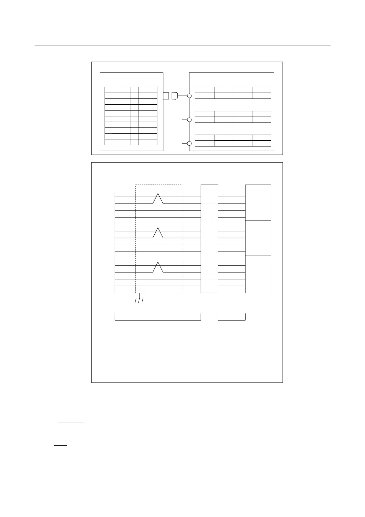
Connection to Manual Pulse Generators
Manual Pulse Generator
I/O unit for 0i
Manual Pulse Generator unit #1
JA3B (PCR-EV20MDT)
(M3 screw terminal)
1
HA1
11
0V
3
4
5
6
2
HB1
12
0V
+5V
0V
HA1
HB1
3
HA2
13
0V
Manual Pulse Generator unit #2
4
HB2
14
0V
(M3 screw terminal)
5
HA3
15
0V
3
4
5
6
6
HB3
16
0V
+5V
0V
HA2
HB2
7
17
+5V
Manual Pulse Generator unit #3
8
18
+5V
(M3 screw terminal)
9
+5V
19
+5V
3
4
5
6
10
+5V
20
+5V
+5V
0V
HA3
HB3
Cable connection
Manual Pulse
T.B.
Generator
#1
1
7 RD
5
HA1
HA1
HA1
2
7 WH
6
HB1
HB1
HB1
9
5 RD
3
+5V
+5V
+5V
12
2 BK
4
0V
0V
0V
#2
3
8 RD
5
HA2
HA2
HA2
4
8 BK
6
HB2
HB2
HB2
18
4 RD
3
+5V
+5V
+5V
14
3 BK
4
0V
0V
0V
#3
5
9 BK
5
HA3
HA3
HA3
6
9 WH
6
HB3
HB3
HB3
20
6 RD
3
+5V
+5V
+5V
16
1 BK
4
0V
0V
0V
shield
Ground Plate
Cable
Wires
Recommended Cable Material (See Appendix B for details of cable material.)
A66L-0001-0286 (#20AWG 6+#24AWG 3) Max.20m
A66L-0001-0402 (#18AWG 6+#24AWG 3) Max.30m
A66L-0001-0403 (#16AWG 6+#24AWG 3) Max.50m
Recommended Cable (except for part of wires)
A02B-0120-K841 (7m) With three manual pulse generators
A02B-0120-K847 (7m) With one manual pulse generator
A02B-0120-K848 (7m) With two manual pulse generators
Cable Length When Manual Pulse Generator is Used
Manual pulse generators are supplied with 5 VDC power the same as pulse coders. The drop in voltage
due to cable resistance must not exceed 0.2V (on 0V and 5V lines in total).
0.1×R×2L
0.2≧
m
where
m
0.1
:
Power supply current for the manual pulse generator = 0.1 A
L≦
R R
:
Wire resistance per unit length [Ω/m]
m
:
Number of 0-V wires (= number of 5-V wires)
L
:
Cable length [m]
- 227 -
9.CONNECTION OF I/O Link SLAVE DEVICES
B-64303EN/03
Therefore,
3
L≦
=76.75 [m]
0.0394
Example: When cable A66L-0001-0286 is used
This cable consists of three pairs of signal lines and six power wires (20/0.18, 0.0394 Ω/m).
When these three cables are used for 0V and 5V lines, the cable length is:
The maximum distance is, however, 50 m for the transmission of a pulse signal from the manual pulse
generator. The cable length is, therefore, up to 50 m.
The maximum cable length is 38.37 m when using the two manual pulse generators, or 25.58 m when
using the three generators.
Manual Handle Allocation Function
Usually, if two or more units equipped with a manual handle interface are connected with an I/O LINK,
the manual handle interface of the first unit connected to the I/O LINK will be automatically enabled.
The use of this function enables the manual handle interfaces of the second and subsequent units. By
setting bit 1 of parameter No. 7105, the manual handles associated with the X addresses set in parameters
Nos. 12305 to 12307 can be allocated as the first, second, and third manual handles, respectively.
Up to three manual handles can be allocated.
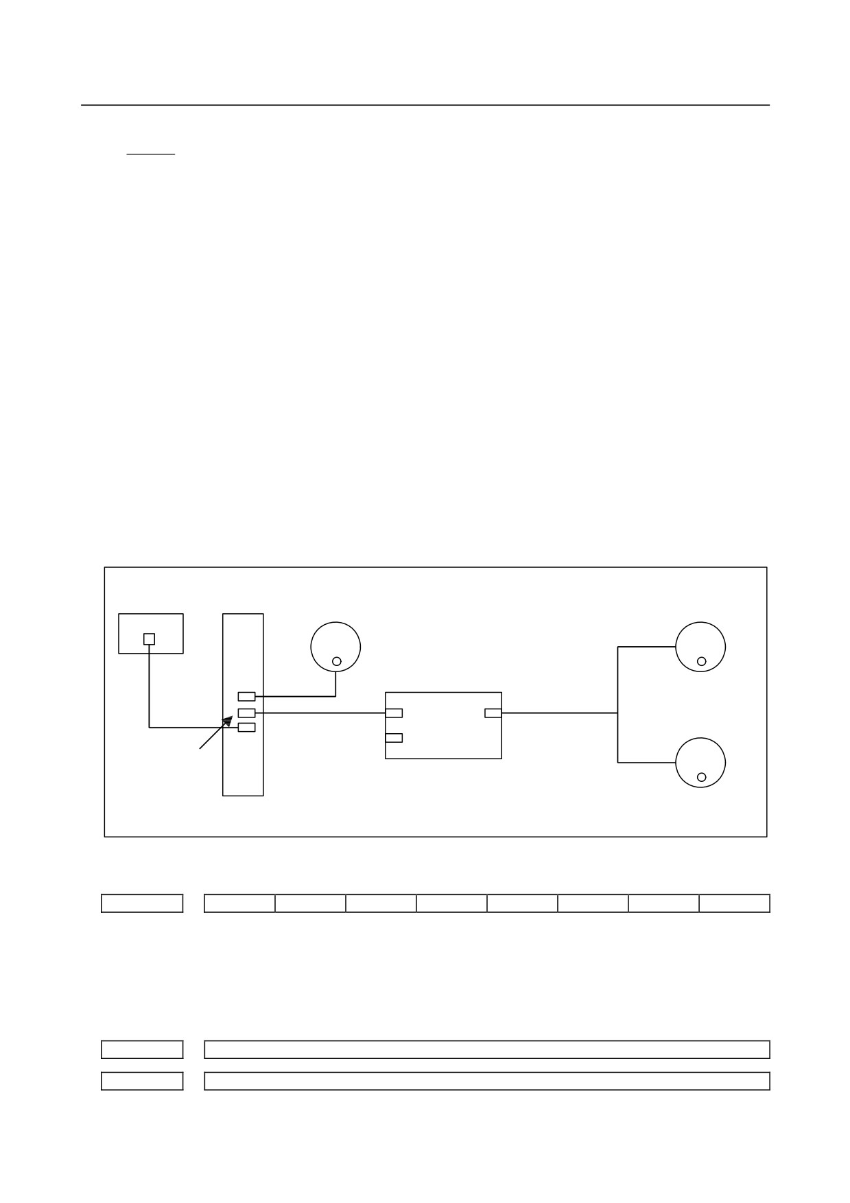
Connection example
Connection example in which more than one unit equipped with a manual handle interface is connected
with an I/O LINK
Manual pulse generator
Manual pulse generator
(No. 1)
(No. 2)
i‚P‘ä-Ú j
i‚Q‘ä-Ú j
CNC
Operator's panel I/O
JA3
Manual pulse generator
JD1B JA3
(No. 3)
i‚R‘ä-Ú j
JD1B
JD1A
JD1A
I/
I/O unit
Parameter
#7
#6
#5
#4
#3
#2
#1
#0
7105
HDX
[Data type] Bit
#1 HDX The manual handles connected with an I/O LINK are:
0: Automatically allocated in the order in which they are connected to the I/O LINK.
1: Allocated to the X signal addresses set in the appropriate parameters.
12300
X signal address associated with the first manual handle
12301
X signal address associated with the secnd manual handle
- 228 -

B-64303EN/03
9.CONNECTION OF I/O Link SLAVE DEVICES
12302
X signal address associated with the third manual handle
[Data type] Word
[Valid data range] 0 to 127
Set the addresses of the X signals used with the respective manual handles.
These parameters are effective when HDX, bit 1 of parameter No. 7105, is 1.
The manual handles will not operate if the addresses of the manual handles of the units
connected with the I/O LINK are not set correctly.
- 229 -
9.CONNECTION OF I/O Link SLAVE DEVICES
B-64303EN/03
9.7
FANUC I/O LINK CONNECTION UNIT
9.7.1
Overview
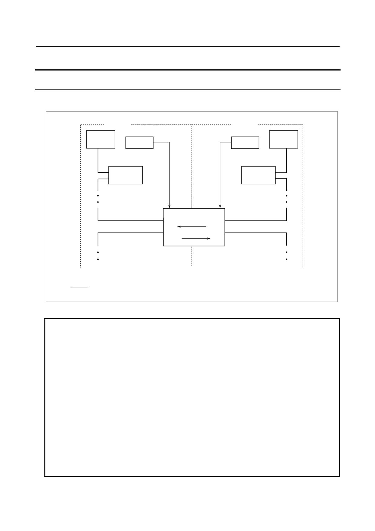
This unit connects FANUC I/O Link master devices' such as the CNC, via an I/O Link to enable the
transfer of DI/DO signals.
System A
System B
CNC
+24 V
power
+24 V power
CNC
supply
supply
I/O Link
I/O Link
SLAVE
SLAVE
FANUC I/O Link
connection unit
DI
DO
DO
DI
I/O Link MASTER : CNC, Power Mate
I/O Link SLAVE : I/O Unit, Power Mate.
: FANUC I/O Link
Fig. 9.7.1 System which uses FANUC I/O Link connection units
This system enable I/O data transfer between two independent FANUC I/O Link
master devices. When the system is adjusted and maintained, the FANUC I/O Link
can be operated with the system power for one of the FANUC I/O Link lines
switched off, that is, the link operation is stopped.
NOTE
Take the following point into consideration when you design your system.
1. If one of the links is stopped, the system power supply is turned off for
maintenance or adjustment, or the link is stopped due to a failure of CNC or
I/O Link slave module, the circuit of this unit is designed so that all DI signals
sent from a system at rest consists entirely of zeros.
2. If one of the links is stopped, either abnormally or normally, it takes up to
several hundred milliseconds for NOTE 1 function to take effect. During this
period, that data which exists immediately before the link stops is sent out.
Take this into account when designing your system.
3. It cannot be guaranteed that the operation described to NOTE 1 and NOTE2
is carried out that way. Therefore, manage signals related to safety by
making a safety circuit outside this FANUC I/O Link connection unit.
- 230 -
B-64303EN/03
9.CONNECTION OF I/O Link SLAVE DEVICES
9.7.2
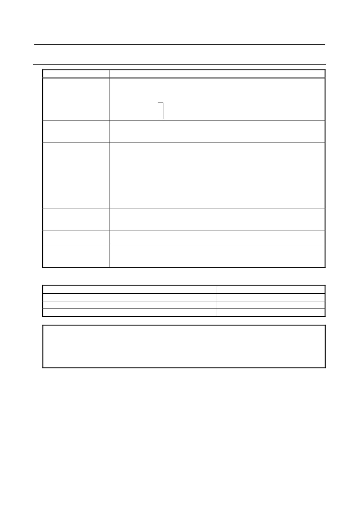
Specification
Item
Specification
I/O Link function
Provided with two slave mode I/O Link interface channels, between which DI/DO data can be
transferred.
[Interface types]
Electrical - optical
Electrical - electrical
One of the following combinations is selected:
Optical - optical
Number of DI/DO data
DI: Up to 256, DO: Up to 256
items
(The number of data items actually used varies depending on the amount of data
assigned in the host.)
Power supply
Each I/O Link interface must be independently supplied with +24 VDC.
Voltage:
+24 VDC +10%, -15%
Current:
0.2 A (excluding surge)
If a master unit does not have sufficient capacity to supply power to each unit (0.2 A per
slot), use an external power supply unit. The power supply must be switched on, either
simultaneously with or before, the I/O Link master.
The two systems can be switched on and off independently of each other. Data from a
system to which no power is supplied appears as zeros when viewed from the other
system. The data becomes 0 within 200 ms of the power being switched off.
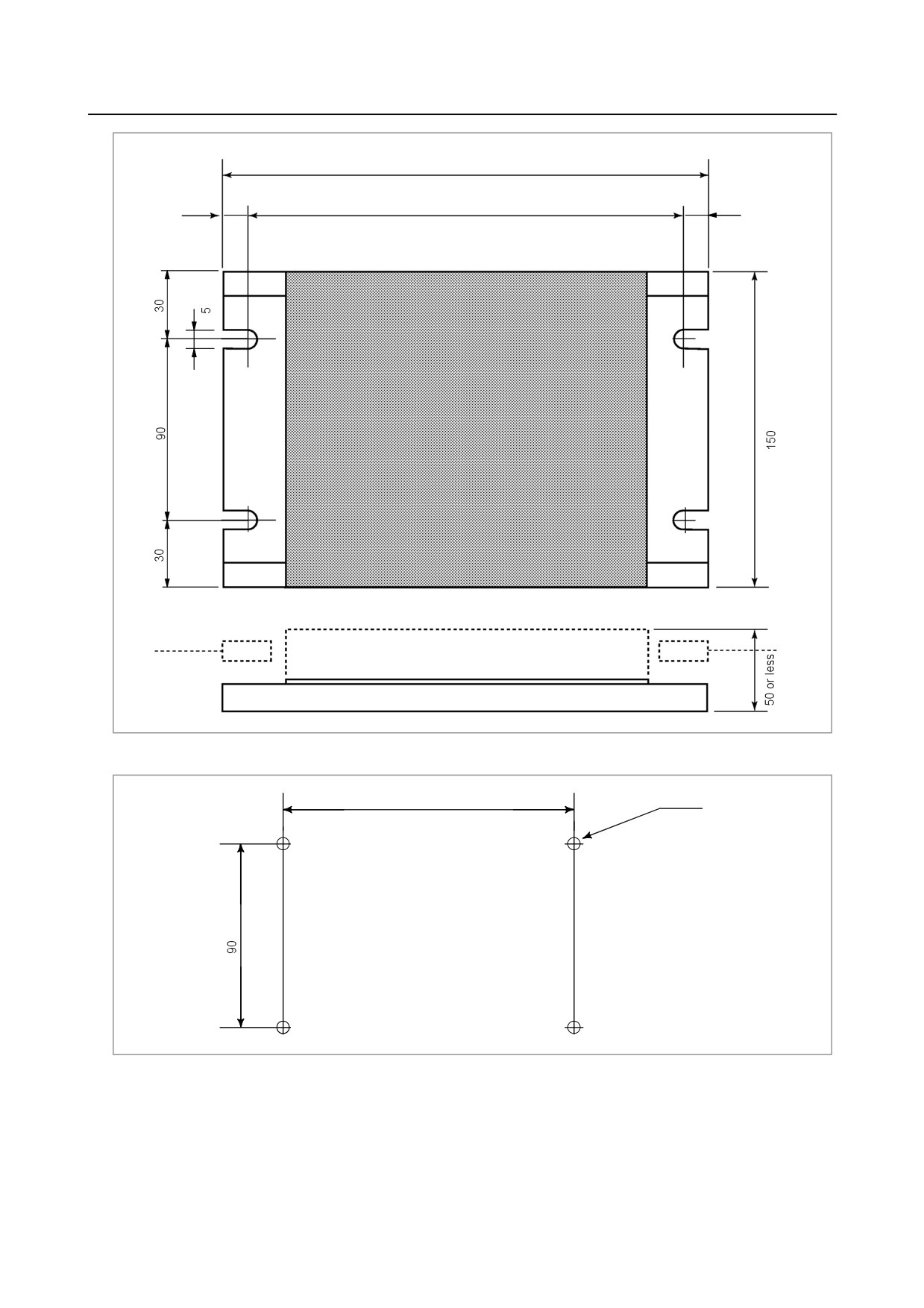
External dimensions
180 mm (width) × 150 mm (height) × about 50 mm (depth)
W
H
D
Fig. 9.7.2 (b) is an outline drawing of the unit.
Installation
The unit, which is a stand-alone type, is installed in the power magnetics cabinet. Fig.
9.7.2 (c) shows how to mount the unit.
Operating environment
Temperature
:
0 to 60°C
Humidity
:
5 to 75% RH (non-condensing)
Vibration
:
0.5 G or less
Ordering information
Interface type
Specification
Electrical-optical interface
A20B-2000-0410
Electrical-electrical interface
A20B-2000-0411
Optical-optical interface
A20B-2000-0412
NOTE
The optical interface of this unit is equivalent to the standard type
(A13B-0154-B001) of an optical I/O Link adapter. Therefore, when this unit is
combined with an optical I/O Link adapter, the optical I/O Link adapter must be
of the standard type (A13B-0154-B001).
- 231 -
9.CONNECTION OF I/O Link SLAVE DEVICES
B-64303EN/03
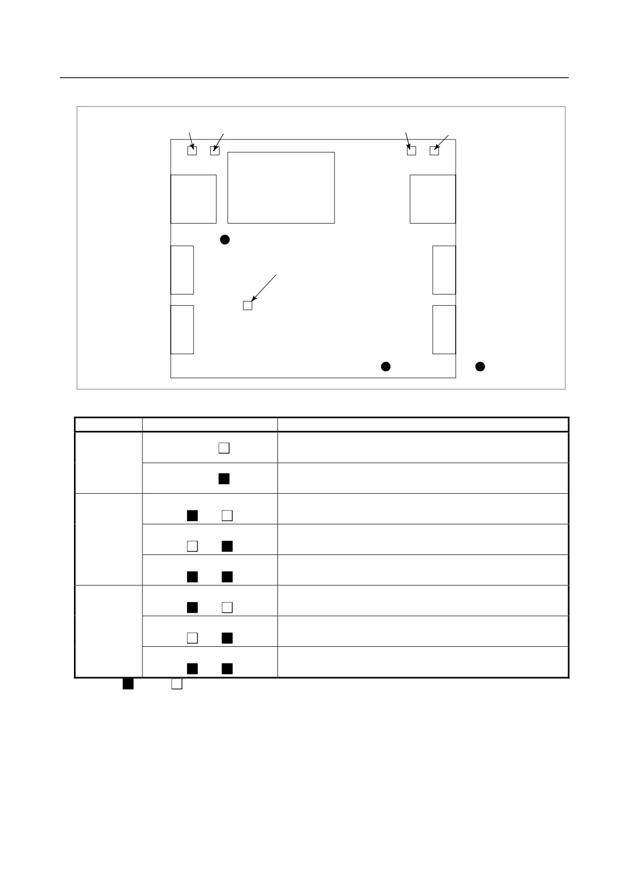
LED indications
LED5
LED3
LED4
LED2
(GREEN)
(RED)
(GREEN)
(RED)
DC-DC
CONVERTER
CP2
CP1
+5V
LED1 (RED)
0V
: Check pin
Fig. 9.7.2 (a) LED locations
LED status
Description
LED1
Normal
1
LED1
A RAM parity error occurred because of a hardware failure.
LED4 LED2
CP1 is supplied with the specified voltage.
(Pilot lamp)
LED4 LED2
2
CP1 is supplied with a voltage that is lower than specified or zero.
LED4 LED2
A communication error occurred in a channel of CP1.
LED5 LED3
CP2 is supplied with the specified voltage.
(Pilot lamp)
LED5 LED3
3
CP2 is supplied with a voltage that is lower than specified or zero.
LED5 LED3
A communication error occurred in a channel of CP2.
: On
: Off
- 232 -
B-64303EN/03
9.CONNECTION OF I/O Link SLAVE DEVICES
Unit: mm
180
10
160
10
Printed-circuit board
Cable
Cable
Mounted components
Fig. 9.7.2 (b) Outline drawing
160
4-M4 Unit: mm
Fig. 9.7.2 (c) Mounting location
- 233 -
9.CONNECTION OF I/O Link SLAVE DEVICES
B-64303EN/03
9.7.3
Connection
9.7.3.1 I/O Link interface
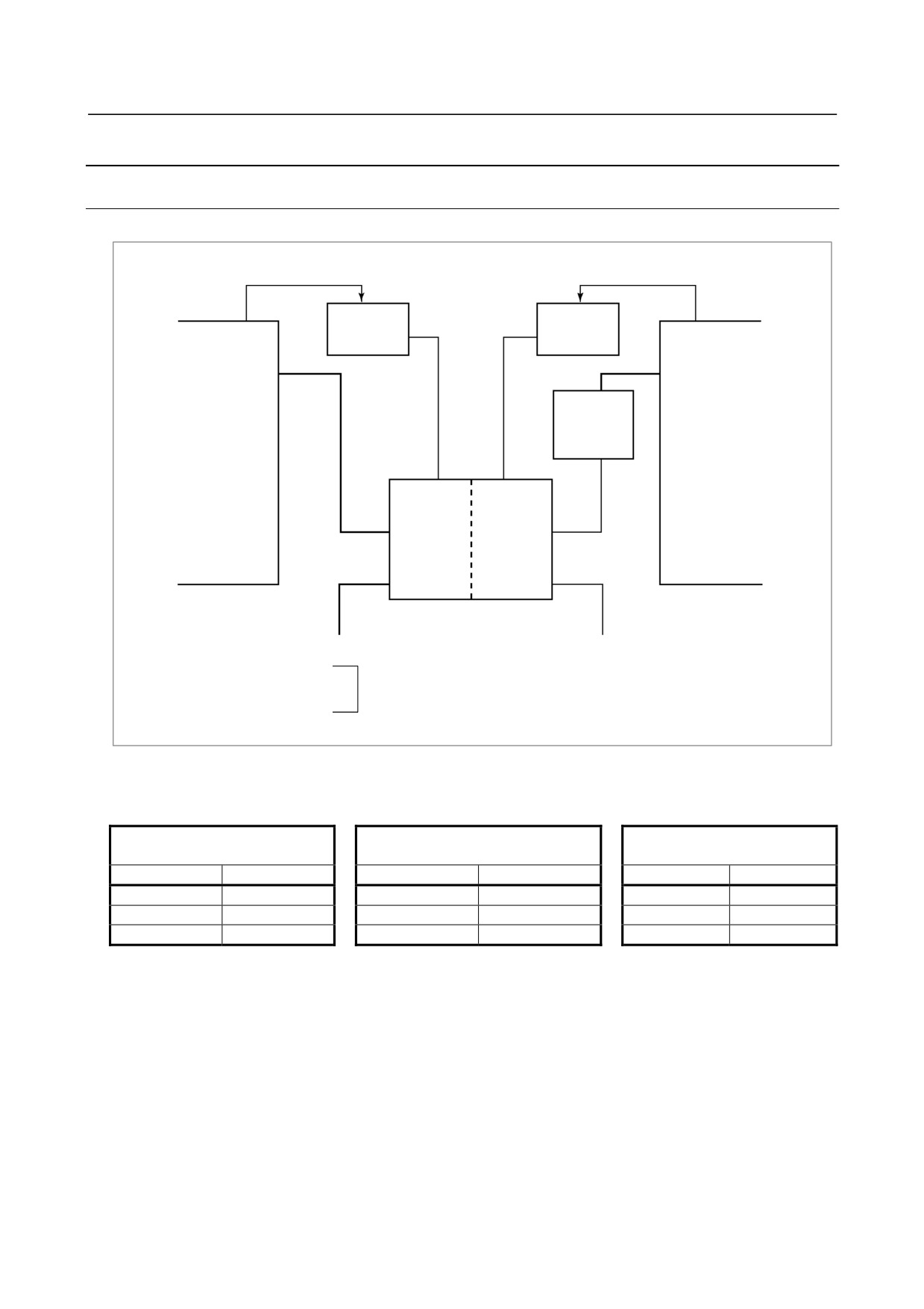
(1)
Connection diagram (example)
AC power input
AC power input
External power
External power
(+24 V)
(+24 V)
I/O Link master
I/O Link master
<3>
<3>
<1>
<1>
JD1A
JD1A
(JD51A)
(JD51A)
Optical I/O
Link adapter
CP*
CP*
<2>
Electrical
Optical
interface
interface
JD1B*
COPB*
JD1A*
COPA*
<1>
<2>
FANUC I/O Link connection unit (for
electrical-optical interface)
(*)
1 or 2 (channel No.)
<1>
: Signal cable (electrical)
Additionally, the FANUC I/O Link connection unit frame must be grounded.
<2>
: Signal cable (optical)
<3>
: Power supply cable
[Name of I/O Link connection unit connectors]
Electrical-optical
Electrical-electrical
Optical-optical
Connector name
Connector name
Connector name
I/O Link interface
I/O Link interface
I/O Link interface
Channel 1
Channel 2
Channel 1
Channel 2
Channel 1
Channel 2
JD1A1
COPA2
JD1A1
JD1A2
COPA1
COPA2
JD1B1
COPB2
JD1B1
JD1B2
COPB
COPB2
CP1
CP2
CP1
CP2
CP1
CP2
- 234 -
B-64303EN/03
9.CONNECTION OF I/O Link SLAVE DEVICES
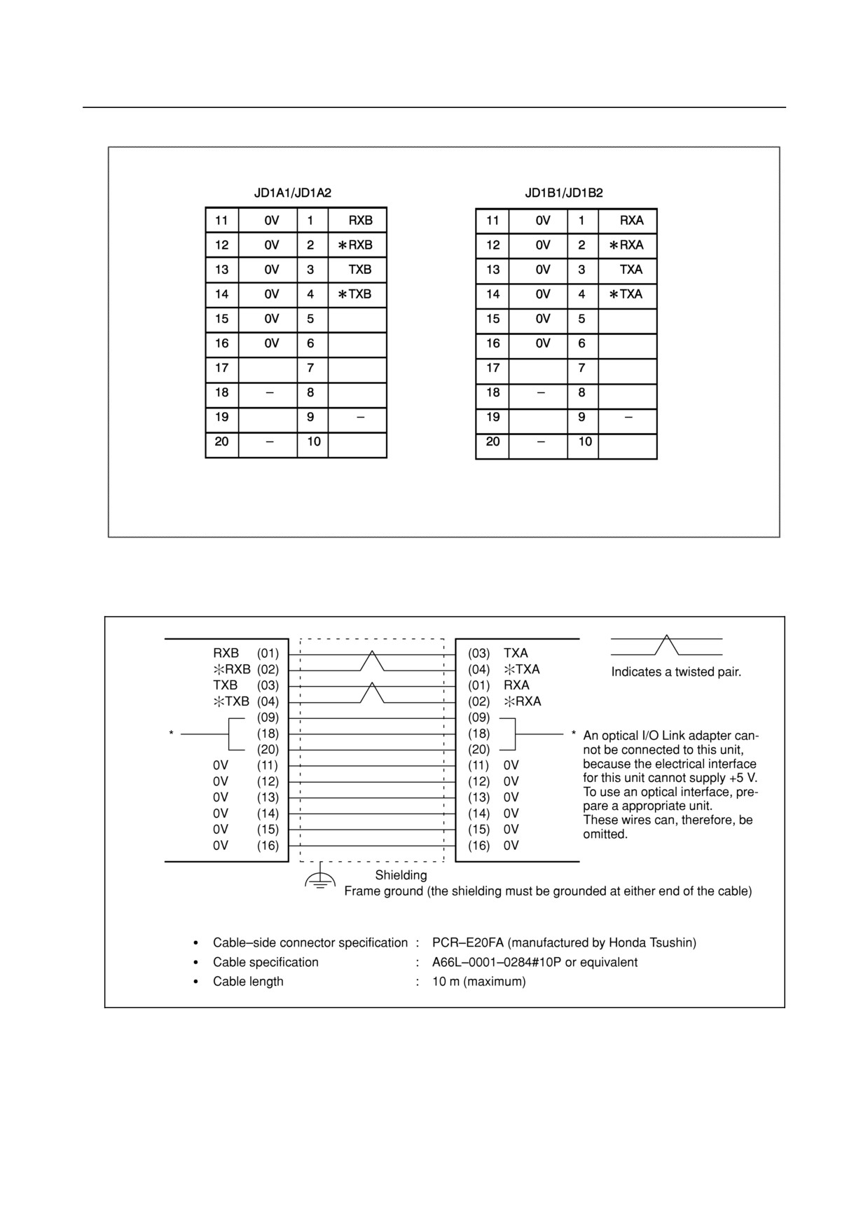
(2) Signal cable (electrical)
This unit (JD1A1/JD1A2) ⇔ Another device (JD1B)
or
Another device (JD1A) ⇔ This unit (JD1B1/JD1B2)
(3) Signal cable (optical)
•
Optical cable specification : A66L-6001-0026#XXXX
(where XXXX is a cable length specification)
Cable specification examples
10m - L10R03
100m - L100R3
•
Cable length : 200 m (maximum)
- 235 -
9.CONNECTION OF I/O Link SLAVE DEVICES
B-64303EN/03
(4) Power supply cable
CP1/CP2 connector
1
2
3
Y
+24V
0V
(Input)
X
+24V
0V
(Output)
•
24 VDC is supplied via a Y-connector. Provided the power supply has sufficient capacity,
power can be supplied to another device with the X-side as output.
•
Power must be supplied to both CP1 and CP2.
•
Cable-side connector specification
Y-connector
: A63L-0001-0460#3LKY (AMP Japan, 2-178288-3)
X-connector
: A63L-0001-0460#3LKX (AMP Japan, 1-178288-3)
Contact: A63L-0001-0456#BS (AMP Japan, 175218-5)
Ordering information:
Y + 3 contacts : A02B-0120-K323
X + 3 contacts : A02B-0120-K324
Cable material :
Vinyl-insulated electrical wire AWG20-16
Cable length
:
Determine the length of the cable such that the supplied voltage at the receiving end
satisfies the requirements, because the voltage may fluctuate and drop as a result of the
resistance of the cable conductor.
(5) Frame grounding
Ground the frame of the unit using a wire having a cross section of at least 5.5 m2 (class 3 or higher).
An M4 frame ground terminal is provided.
9.8
CONNECTING THE FANUC SERVO UNIT β SERIES WITH
I/O LINK
9.8.1
Overview
The FANUC servo unit β series with I/O Link (called the β amplifier with I/O Link) is a servo unit that
can be easily connected to a CNC control unit via the FANUC I/O Link.
- 236 -
B-64303EN/03
9.CONNECTION OF I/O Link SLAVE DEVICES
9.8.2
Connection
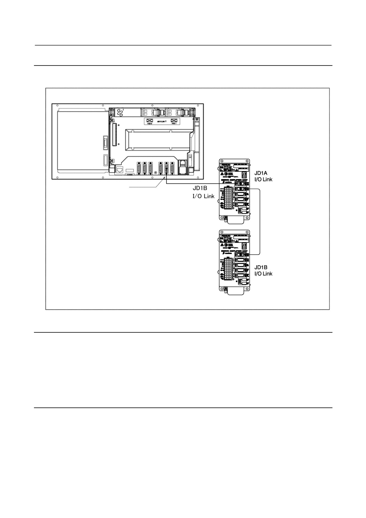
The β amplifier with I/O Link is connected to the control unit using the usual FANUC I/O Link
connection.
Control unit
FANUC Servo Unit β series
with I/O Link
I/O Link connector [JD51A]
I/O Link cable
Connection to β amplifier
9.8.3
Maximum Number of Units that can be Connected
For the 0i-D, the maximum number of β amplifiers with I/O Link that can be connected to a control unit
depends on the maximum number of FANUC I/O Link points provided by that control unit, as well as
their assignments. The maximum number of DI/DO points of the FANUC I/O Link is 1024/1024. On
the other hand, the number of DI/DO points occupied by a β amplifier with I/O Link is 128/128. So, if
only β amplifiers with I/O Link are connected to the FANUC I/O Link, up to eight β amplifiers with I/O
Link can be connected. For the 0i Mate, number of connectable amplifiers depends on the model.
9.8.4
Address Assignment by Ladder
If the β amplifier with I/O Link is used as an I/O Link slave, I/O addresses are assigned in the PMC in the
CNC. Because data output from the slave is made in 16-byte units, the number of input/output points
must be set to 128.
The module names are OC02I (input) and OC02O (output).
The BASE is always 0, and the SLOT is 1.
- 237 -
9.CONNECTION OF I/O Link SLAVE DEVICES
B-64303EN/03
9.9
CONNECTION TO STANDARD MACHINE OPERATOR'S
PANEL
9.9.1
Overview
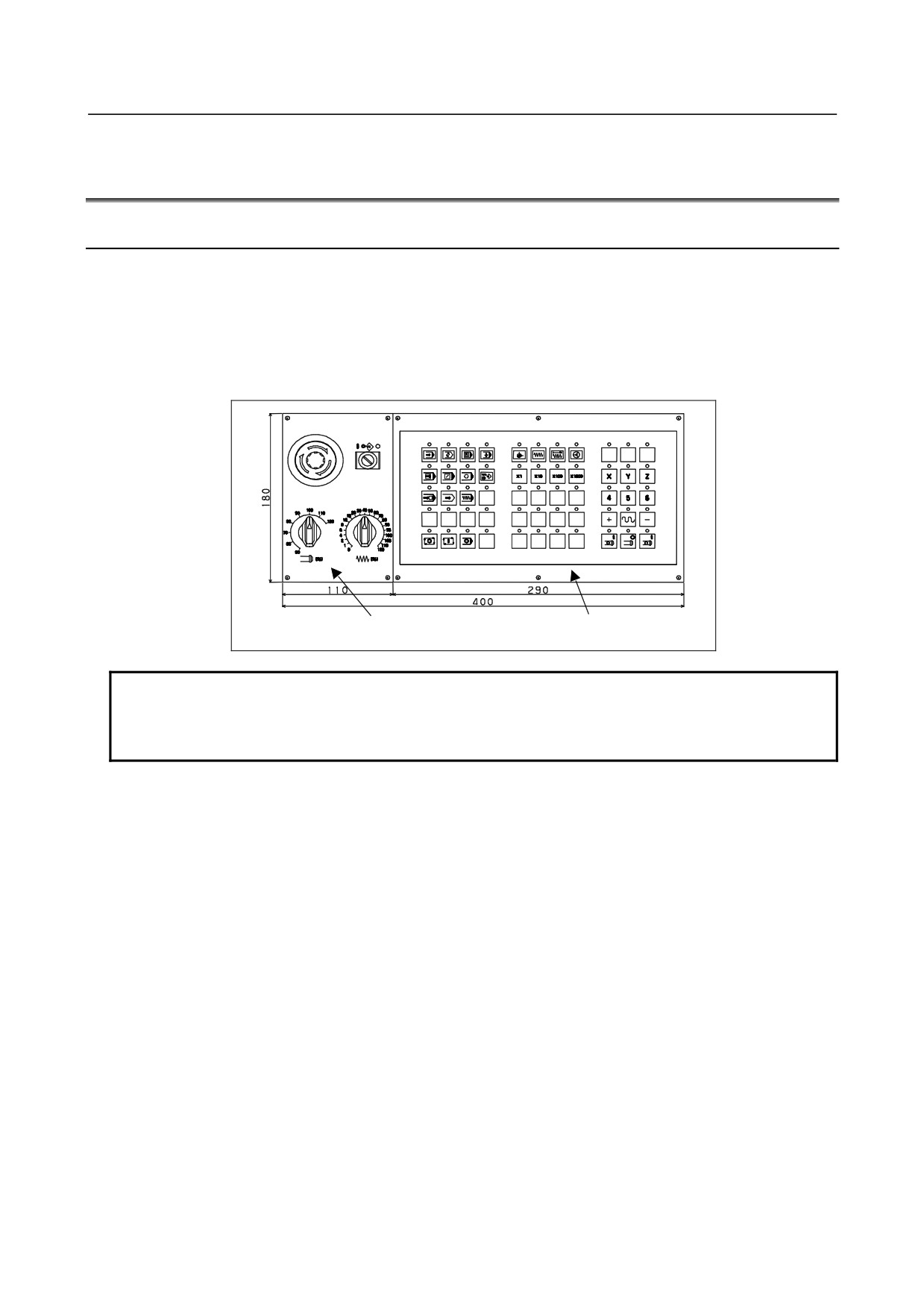
Standard machine operator's panel is connected with CNC by I/O Link, which is composed by some
following operator's panels.
Main panel
All key tops are detachable. MTB can customize keys and make his original key layout easily.
Sub panel
Operator's panel with switches such as an emergency stop switch, memory protect switch, and rotary
switch for override
Sub panel
Main panel
NOTE
As the main panel for a standard machine operator's panel, use a 3-keystroke
support model, which does not accept more than three simultaneous keystrokes.
See Subsection 9.9.6.2, "Order specification".
- 238 -
B-64303EN/03
9.CONNECTION OF I/O Link SLAVE DEVICES
9.9.2
Total Connection Diagram
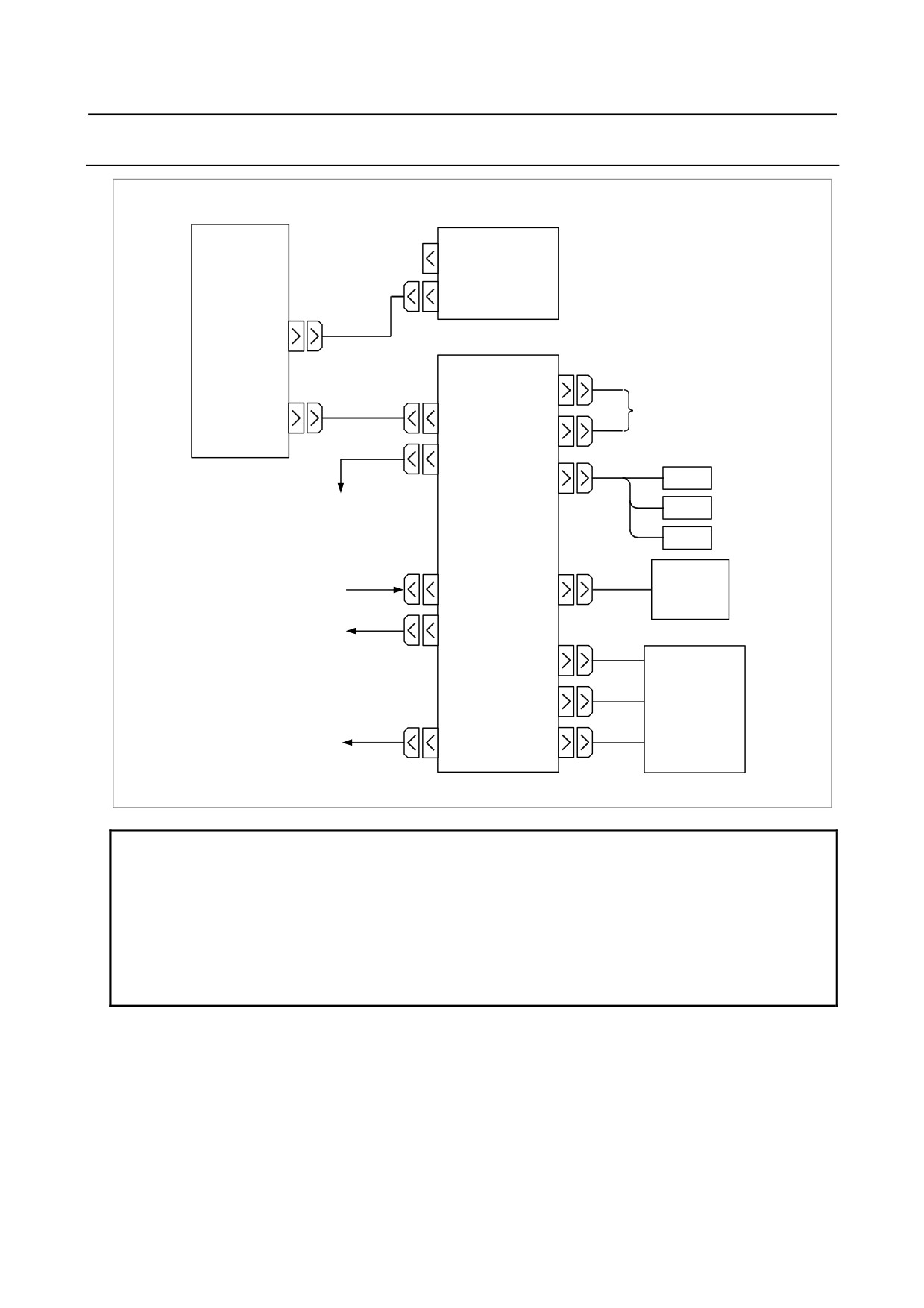
CNC
Standard MDI Unit
CNK2
CNK1
MDI(JA1)
Main panel
Machine operator's
section
CM68
I/O Link(JD1A)
General-purpose DI/DO
(JD51A)
JD1B
CM69
JD1A
JA3
MPG
Next I/O unit
MPG
MPG
Pendant type
+24V Power supply
CA64(IN)
JA58
MPG
+24V Power supply
CA64(OUT)
Sub panel
(SA1)
CM65
(SA2)
CM66
Power magnetics cabinet
CA65
CM67
(SA3,SB1~3)
NOTE
1 This CNC is only possible to use the MPG interface on this operator's panel. If
Series 0i uses some I/O unit having MPG interface (ex. Dispersion type I/O
module for panel) and this operator's panel, the MPG interface nearest the CNC
is only available on the I/O Link connection.
To enable the MPG interface of a second or subsequent unit, use the manual
handle allocation function.
2 MPG cannot be connected with either of JA3 and JA58.
- 239 -
9.CONNECTION OF I/O Link SLAVE DEVICES
B-64303EN/03
9.9.3
Each Connections
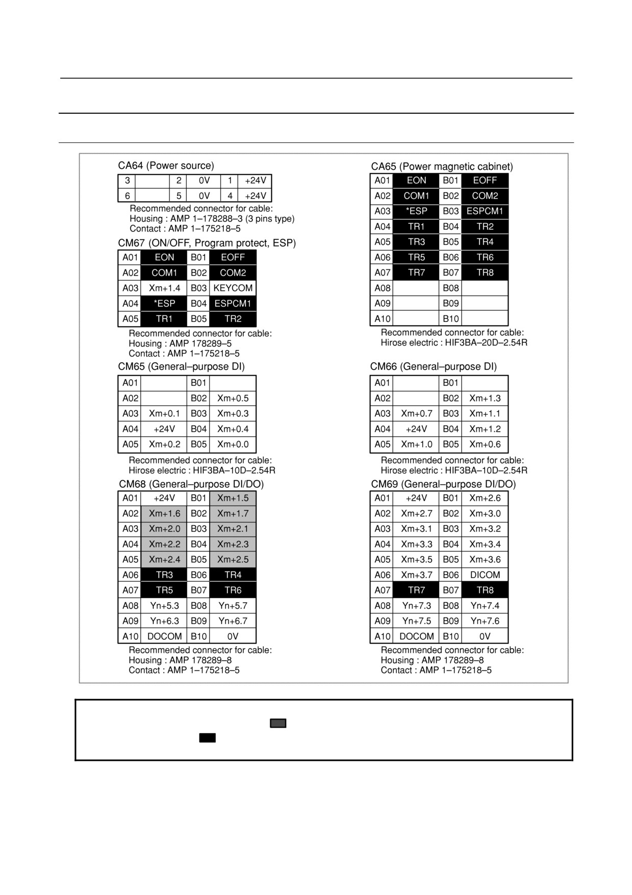
9.9.3.1 Pin assignment
NOTE
Input/output Pins shaded by
are in pairs. Only one in each pair is usable.
Pins shaded by
are those for forwarding signals. Pins with the same name
are connected directly to one another.
- 240 -
B-64303EN/03
9.CONNECTION OF I/O Link SLAVE DEVICES
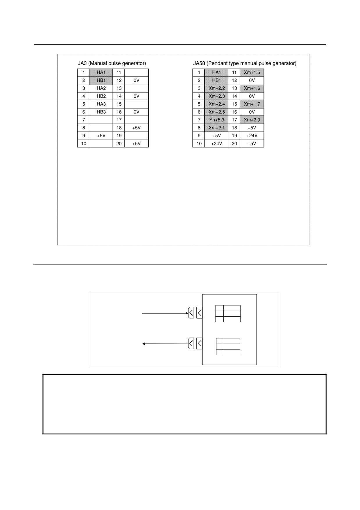
Recommended connector for cable of JA3 and JA58
When the depth of the operator's panel is 60mm min.
Hirose electric :FI30-20S (Connector), FI-20-CV7 (Case)
When the depth of the operator's panel is 80mm min.
Recommended connector for cable of JA3:
Hirose electric : FI40B-2015S (Connector), FI-20-CV (Case)
Recommended connector for cable of JA58:
Honda : PCR-E20FA (Connector), PCR-V20LA (Case)
Hirose electric : FI30-20S (Connector), FI-20-CV2 (Case)
Fujitsu : FCN-247J020-G/E (Connector), FCN-240C020-Y/S (Case)
Molex : 52622-2011 (Connector), 52624-2015 (Case)
9.9.3.2 Power supply connection
The power required for the operation of this operator's panel and for a general DI must be supplied to
connector CA64 (IN) in the following figure. Since the power input from CA64 (IN) is output to CA64
(OUT) for easy branching, use the power from CA64 (OUT) when the power must be branched.
CA64(IN)
01
+24V
24VDC power
02
0V
03
CA64(OUT)
01
+24V
24VDC power¹
02
0V
03
NOTE
1 Both connectors CA64(IN) and CA64(OUT) are same specification. And there is
not indication of (IN) and (OUT) on the PCB.
2 Power supply for the operator's panel must not turn off at operation. If +24V is
turned off at operation, CNC happen to get system alarm(Communication alarm
between CNC and operator's panel). +24V for operator's panel must be supplied
before or same time CNC power on.
- 241 -
9.CONNECTION OF I/O Link SLAVE DEVICES
B-64303EN/03
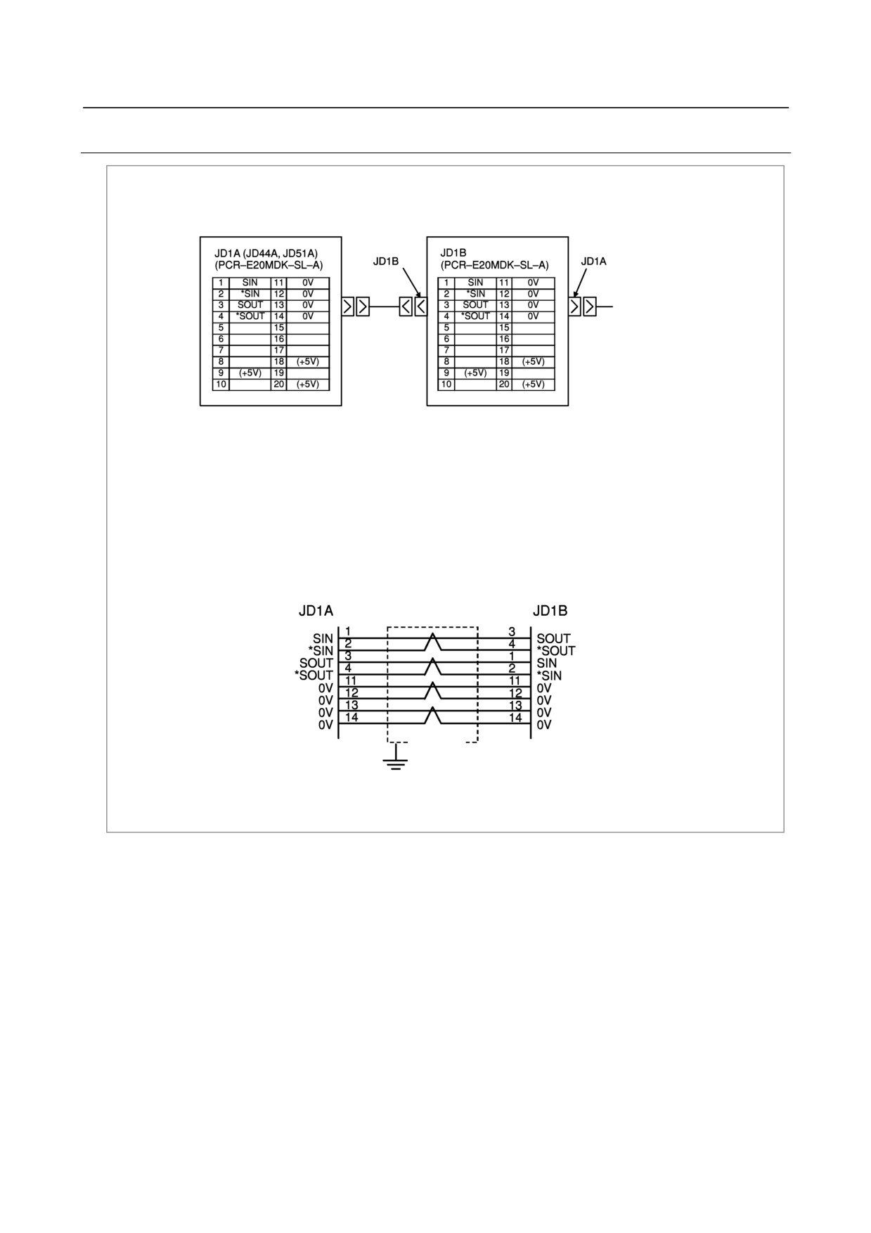
9.9.3.3 I/O Link connection
Control unit preceding slave unit
Main panel
Next slave unit
r cable of JD1A and JD1B on Main panel
tor's panel is 60mm min.
(Connector), FI-20-CV7 (Case)
tor's panel is 80mm min.
nnector), PCR-V20LA (Case)
(Connector), FI-20-CV2 (Case)
E (Connector), FCN-240C020-Y/S (Case)
nector), 52624-2015 (Case)
+5V terminals are for an optical I/O Link adapter. They are not necessary when connecting with a metal cable.
A line for the +5V terminal is not required when the Optical I/O Link Adapter is not used.
Shield
Ground
plate
Recommended wire material:
A66L-0001-0284#10P (#AWG28 × 10 pairs)
- 242 -
B-64303EN/03
9.CONNECTION OF I/O Link SLAVE DEVICES
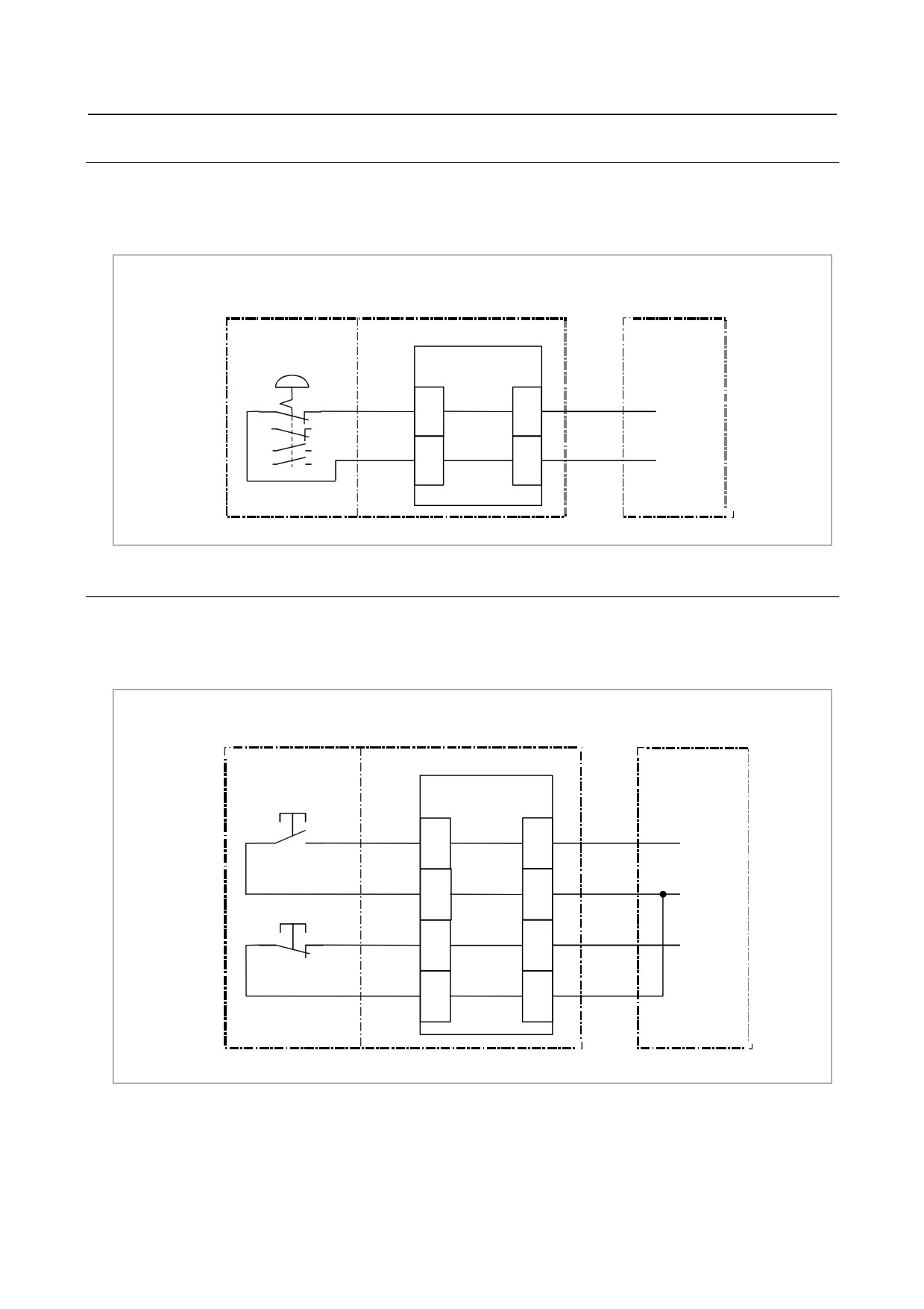
9.9.3.4 Emergency stop signal connection
A signal generated by the emergency stop switch on the standard machine operator's panel can be sent to
the power magnetics cabinet. (This signal cannot be sent to the FANUC I/O Link.)
When MTB uses the Sub panel A/D, wiring to the emergency stop switch is contained in the Sub panel
A/D.
Machine operator's panel
Sub panel A/D
Main panel
Power
Emergency stop switch
magnetics
(SB1)
P.C.B.
cabinet
CM67
CA65
*ESP
*ESP
A04
A03
*ESP
(2a2b)
ESPCM1
ESPCM1
B04
B03
+24V
9.9.3.5 Power ON/OFF control signal connection
Signal generated by the power ON/OFF control switches on the standard machine operator's panel can be
sent to the power magnetics cabinet. (This signal cannot be sent to the FANUC I/O Link.)
When MTB uses the Sub panel A/D, wiring to the ON/OFF control switches are contained in the Sub
panel A/D.
Machine operator's panel
Sub panel A/D
Main panel
Power magnetics
cabinet
P.C.B.
ON switch (SB2)
CM67
CA65
EON
A01
A01
EON
COM1
A02
A02
COM
OFF switch (SB3)
EOFF
B01
B01
EOFF
COM2
B02
B02
- 243 -
9.CONNECTION OF I/O Link SLAVE DEVICES
B-64303EN/03
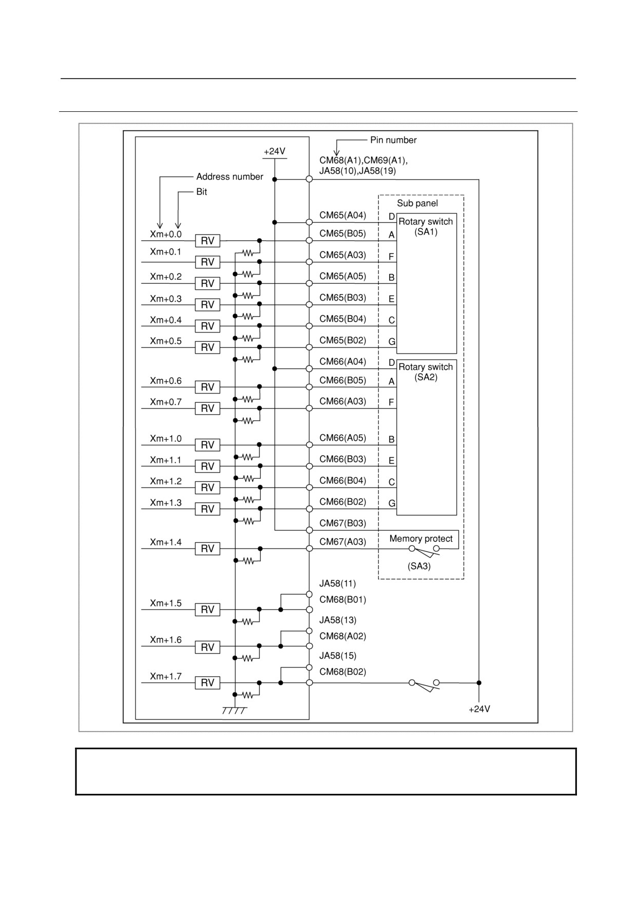
9.9.3.6 General-purpose DI signal connection
NOTE
Connection of Xm+0.0 to Xm+0.7, Xm+1.0 to Xm+1.4 shows when the Sub
panel is used.
- 244 -
B-64303EN/03
9.CONNECTION OF I/O Link SLAVE DEVICES
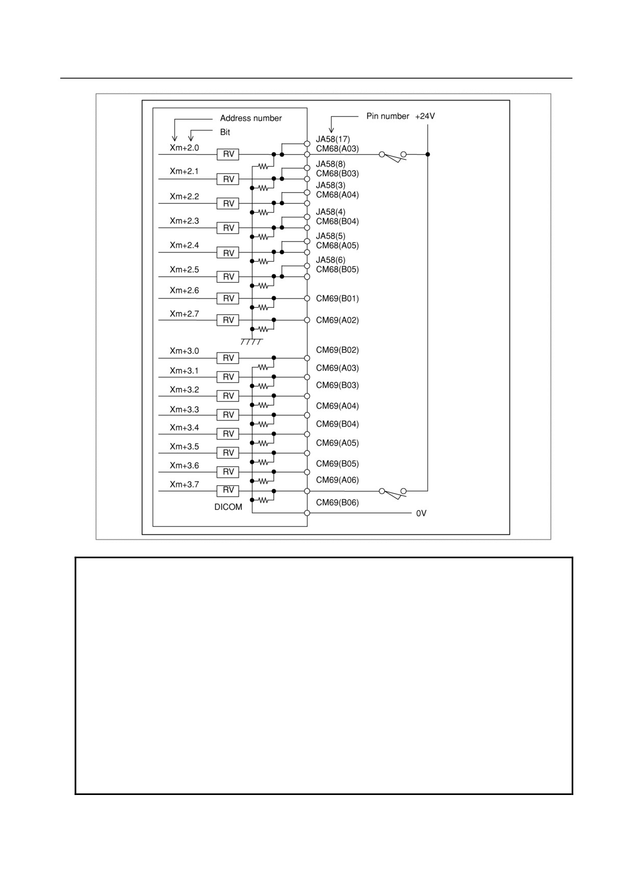
NOTE
1 Xm+3.0 to 3.7 have a common line that is possible to select the source/sink
type. If DICOM (CM69-B06pin) is connected to +24V, the DI signal logic is
negative. But in this connection, if the DI signal wires happen to drop the ground
level, the status of the DI signal is same as the DI signal is "ON". From the
safety viewpoint, DICOM should be connected 0V.
2 From the safety viewpoint, Emergency Stop signal must be assigned on the
address Xm+0.0 to 0.7 or Xm+1.0 to 1.7 or Xm+2.0 to 2.7. As refer to the 5.
DI/DO mapping, assign the Emergency stop DI.
3 Xm+0.0 to 0.7, Xm+1.0 to 1.7 and Xm+2.0 to 0.7 common lines are fixed. So, if
these DI pins in this address open, the status of these one stay "0". And in case
of Xm+3.0 to 3.7 which have a selectable common line, if the DICOM
(CM69-B06pin) is connected to 0V and these DI pins open, the status of these
one stay "0". And if the DICOM are connected to +24V and these DI pins open,
the status of these one stay "1". And if the DICOM is not connected to 0V or
+24V and these DI pins open, the status of these one don't care.
- 245 -
9.CONNECTION OF I/O Link SLAVE DEVICES
B-64303EN/03
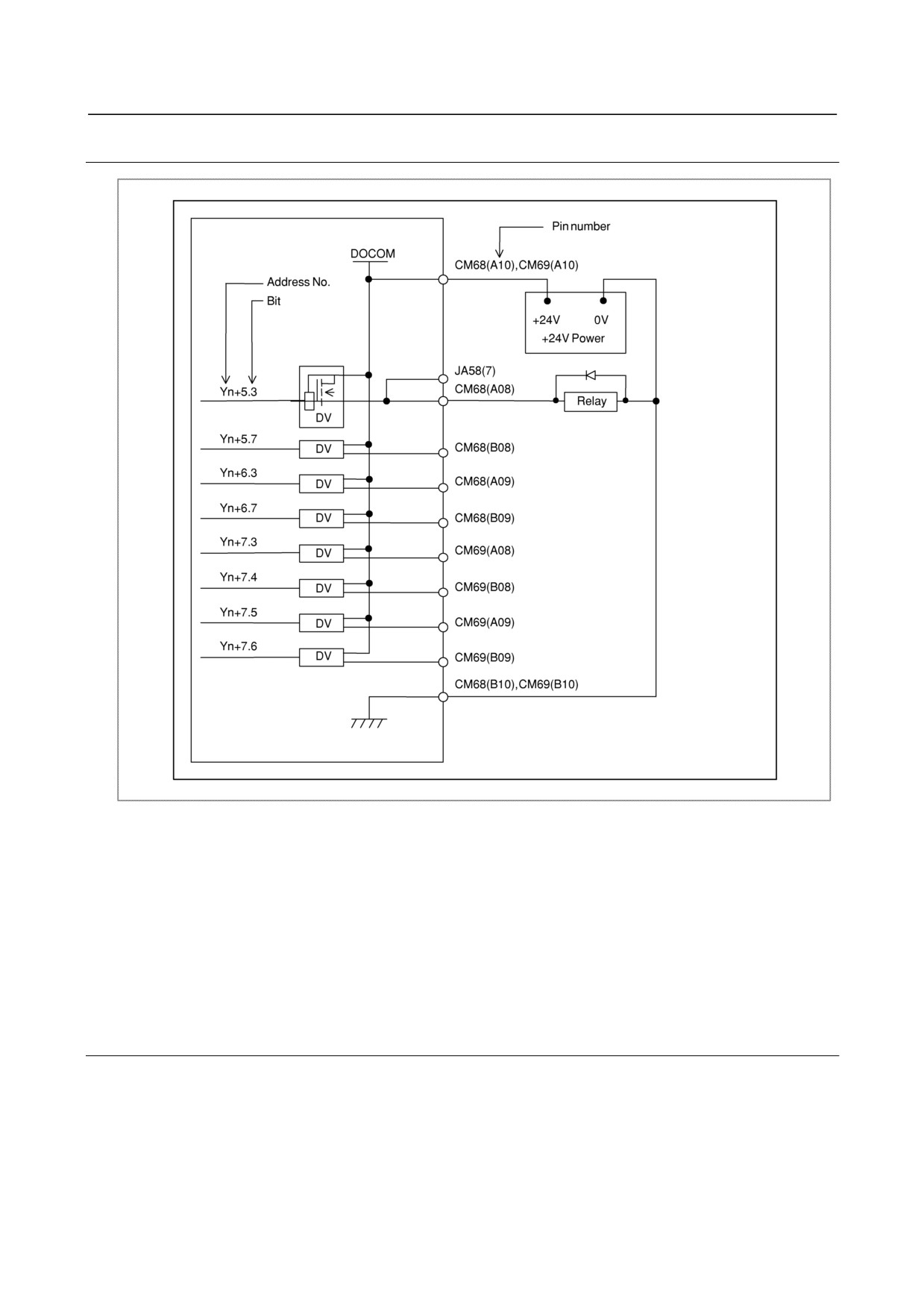
9.9.3.7 General-purpose DO signal connection
DO signal reaction to a system alarm
There is a possibility that the Operator’s panel will not operate normally due to a failure of CNC or I/O
Link slave module, or abnormally power supply voltage. To prevent accidents even in this case, design
the machine to operate safely by making a safety circuit outside the Operator’s panel.
The circuit of this Operator’s panel is designed so that all DO signals are turned off if a system alarm is
occurred in the CNC which controls the Operator’s panel, or if a power of the CNC or the Operator’s
panel is turned off. However, it cannot be guaranteed that DO signals of the Operator’s panel will
certainly be turned off. Therefore, manage signals related to safety by making a safety circuit outside this
Operator’s panel.
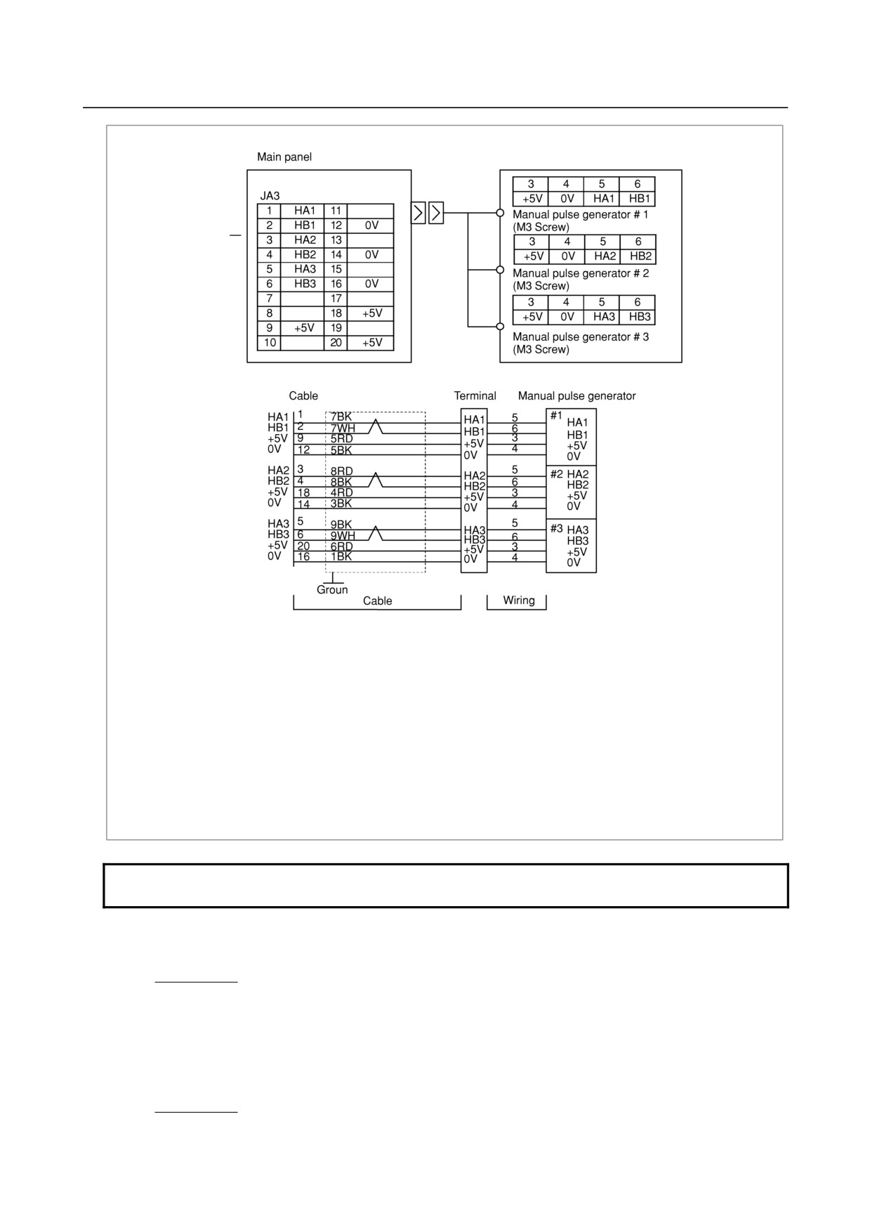
9.9.3.8 Manual pulse generator connection
When only the manual pulse generator.
Example of the 3 manual pulse generator connection is as follows. If this CNC uses some I/O unit having
MPG interface (ex. Dispersion type I/O module for panel) and this operator's panel, the MPG interface
nearest the CNC is only available on the I/O Link connection.
- 246 -
B-64303EN/03
9.CONNECTION OF I/O Link SLAVE DEVICES
When the depth of the operator's panel is 80mm min.
Recommended wire material : A66L-0001-0286(#20AWG × 6+#24AWG × 3 pairs)
Recommended connector : A02B-0120-K303 (Including below connector and case)
(Connector : HIROSE FI40B-2015S Soldering type)
(Case : HIROSE FI-20-CV)
Recommended cable : A02B-0120-K841(7m) (MPG 3 units)
A02B-0120-K848(7m) (MPG 2 units)
A02B-0120-K847(7m) (MPG 1 unit)
(These cables don't include the wiring part in the figure.)
When the depth of the operator's panel is 60mm min.
Recommended wire material : A66L-0001-0284#10P(#28AWG × 10pairs)
Recommended connector :
A02B-0236-K302 (Including below connector and case)
(Connector : HIROSE FI30-20S Stand wire press-mount type)
(Case : HIROSE FI-20-CV7)
NOTE
Calculate the MPG cable max. Length as refer to the following calculation.
MPG needs a 5VDC power supply and the voltage must be less than 0.2V dropping. (the 0.2V dropping
includes the resistance in the cable.)
0.1×R×2L
0.2≥
m
0.1
: MPG power supply current 0.1A
R
: Resistance per wire length (Ω/m)
m
: Wire Number (Both 0V and 5V)
L
: Cable length (m)
Because
m
L≤
R
- 247 -
9.CONNECTION OF I/O Link SLAVE DEVICES
B-64303EN/03
Example: In case of cable A66L-0001-0286
It has 3 pairs signal wires and 6 power line wires (20/0.18, 0.0394 Ω/m).
If the cable is used and each 3 wires are used for 0V and 5V power line, then max. cable length is as
follows.
3
L≤
=76.75(m)
0.0394
The answer is 76.75m, if MPG unit is 1.
(But FANUC decide any cable must be less than 50m.)
The answer is 38.37m, if MPG units are 2.
The answer is 25.58m, if MPG units are 3.
And In case of cable A66L-0001-0284#10P
The answer is 12.88m, if MPG units are 1.
The answer is 6.44m, if MPG units are 2.
The answer is 4.29m, if MPG units are 3.
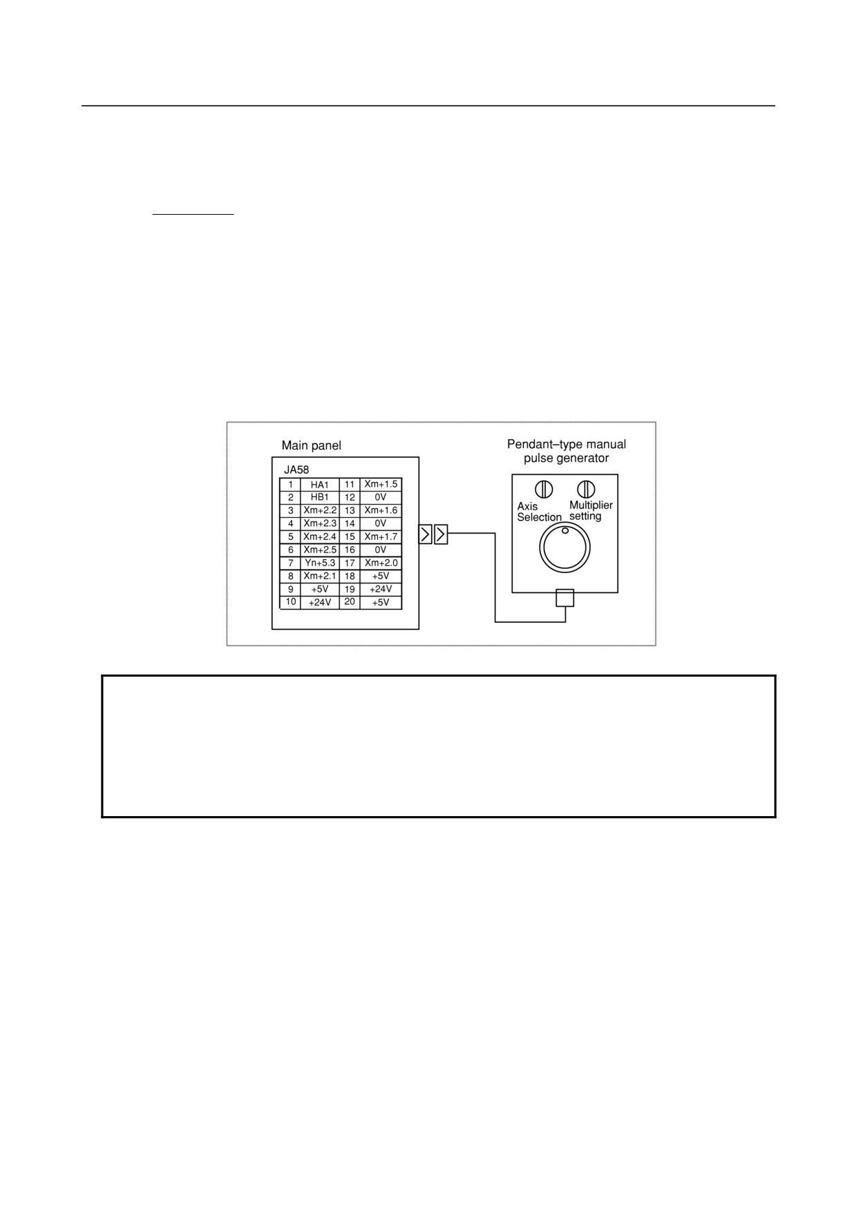
When a pendant-type manual pulse generator
NOTE
1 When Xm+1.5 to Xm+2.5 of connector JA58 are allocated as the Dis used for
the axis selection and multiplier setting, Xm+1.5 to Xm+2.5 of connector CM68
cannot be used.
2 One DO is available for the manual pulse generator side at the user's direction.
When this is used, Yn+5.3 of CM68 cannot be used, as in the case for DIs
above.
- 248 -
B-64303EN/03
9.CONNECTION OF I/O Link SLAVE DEVICES
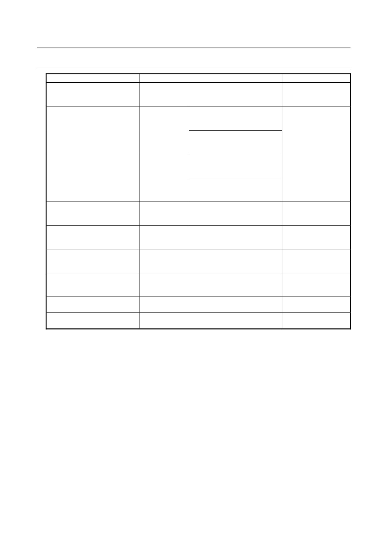
9.9.3.9 Connector (on the cable side) specifications
Connector
Manufacture specification
Order specification
JD1A, JD1B, JA3, JA58
Stand wire
Hirose
A02B-0236-K302
(Operators panel depth=60mm
press-mount type
FI30-20S (Connector)
min.)
FI-20-CV7 (Case)
JD1A, JD1B, JA58
Soldering type
Honda
A02B-0120-K301
(Operators panel depth=80mm
PCR-E20FS (Connector)
min.)
PCR-V20LA (Case)
Hirose
FI40B-20S (Connector)
FI-20-CV2 (Case)
Stand wire
Honda
A02B-0120-K302
press-mount type
PCR-E20FA (Connector)
PCR-V20LA (Case)
Hirose
FI30-20S (Connector)
FI-20-CV2 (Case)
JA3 (Operators panel
Soldering type
Hirose
A02B-0120-K303
depth=80mm min.)
FI40B-2015S (Connector)
FI-20-CV (Case)
CA64 (IN),
AMP
A02B-0120-K324
CA64 (OUT)
1-178288-3 (Housing)
1-175218-5 (Contact)
CM67
AMP
A02B-0236-K312
178289-5 (Housing)
1-175218-5 (Contact)
CM68,
AMP
A02B-0236-K313
CM69
178289-8 (Housing)
1-175218-5 (Contact)
CM65,
Hirose
A02B-0236-K314
CM66
HIF3BA-10D-2.54R
CA65
Hirose
A02B-0120-K343
HIF3BA-20D-2.54R
- 249 -
9.CONNECTION OF I/O Link SLAVE DEVICES
B-64303EN/03
9.9.4
I/O Address
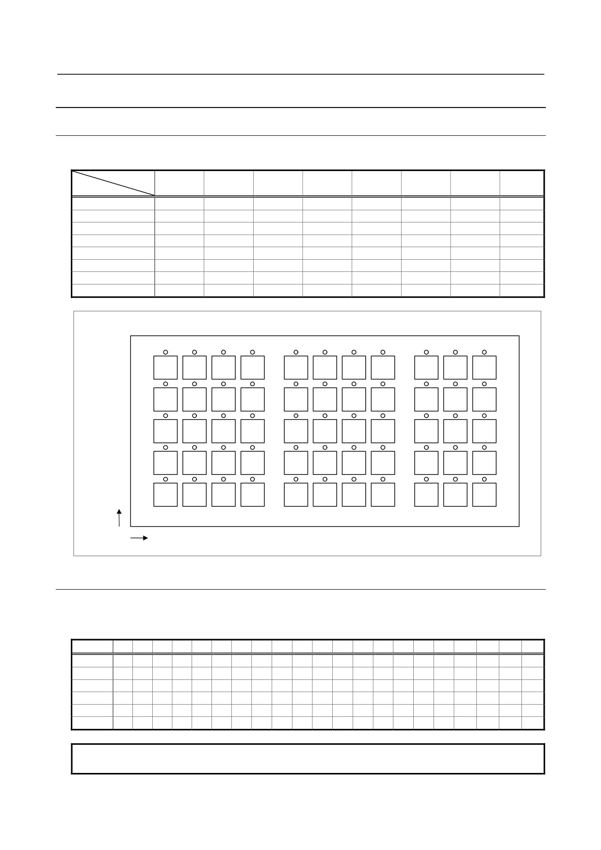
9.9.4.1 Keyboard of main panel
I/O address of Keyswitches and LED on the keyboard of Main panel are as follows.
BIT
7
6
5
4
3
2
1
0
Key/LED
Xm+4/Yn+0
B4
B3
B2
B1
A4
A3
A2
A1
Xm+5/Yn+1
D4
D3
D2
D1
D4
C3
C2
C1
Xm+6/Yn+2
A8
A7
A6
A5
E4
E3
E2
E1
Xm+7/Yn+3
C8
C7
C6
C5
B8
B7
B6
B5
Xm+8/Yn+4
E8
E7
E6
E5
D8
D7
D6
D5
Xm+9/Yn+5
B11
B10
B9
A11
A10
A9
Xm+10/Yn+6
D11
D10
D9
C11
C10
C9
Xm+11/Yn+7
E11
E10
E9
Keyswitches / LED position
A
B
C
D
E
Address
1
2
3
4
5
6
7
8
9
10
11
9.9.4.2 Override signals
When a Sub panel is used, gray code is output from each rotary switch according to the following table:
Rotary switch (SA1)
%
0
1
2
4
6
8
10
15
20
30
40
50
60
70
80
90
95
100
105
110
120
Xm+0.0
0
1
1
0
0
1
1
0
0
1
1
0
0
1
1
0
0
1
1
0
0
Xm+0.1
0
0
1
1
1
1
0
0
0
0
1
1
1
1
0
0
0
0
1
1
1
Xm+0.2
0
0
0
0
1
1
1
1
1
1
1
1
0
0
0
0
0
0
0
0
1
Xm+0.3
0
0
0
0
0
0
0
0
1
1
1
1
1
1
1
1
1
1
1
1
1
Xm+0.4
0
0
0
0
0
0
0
0
0
0
0
0
0
0
0
0
1
1
1
1
1
Xm+0.5
0
1
0
1
0
1
0
1
0
1
0
1
0
1
0
1
0
1
0
1
0
NOTE
Xm+0.5 is a parity bit.
- 250 -
B-64303EN/03
9.CONNECTION OF I/O Link SLAVE DEVICES
Rotary switch (SA2)
%
50
60
70
80
90
100
110
120
Xm+0.6
0
1
1
0
0
1
1
0
Xm+0.7
0
0
1
1
1
1
0
0
Xm+1.0
0
0
0
0
1
1
1
1
Xm+1.1
0
0
0
0
0
0
0
0
Xm+1.2
0
1
0
1
0
1
0
1
Xm+1.3
0
0
0
0
0
0
0
0
NOTE
Xm+1.2 is a parity bit.
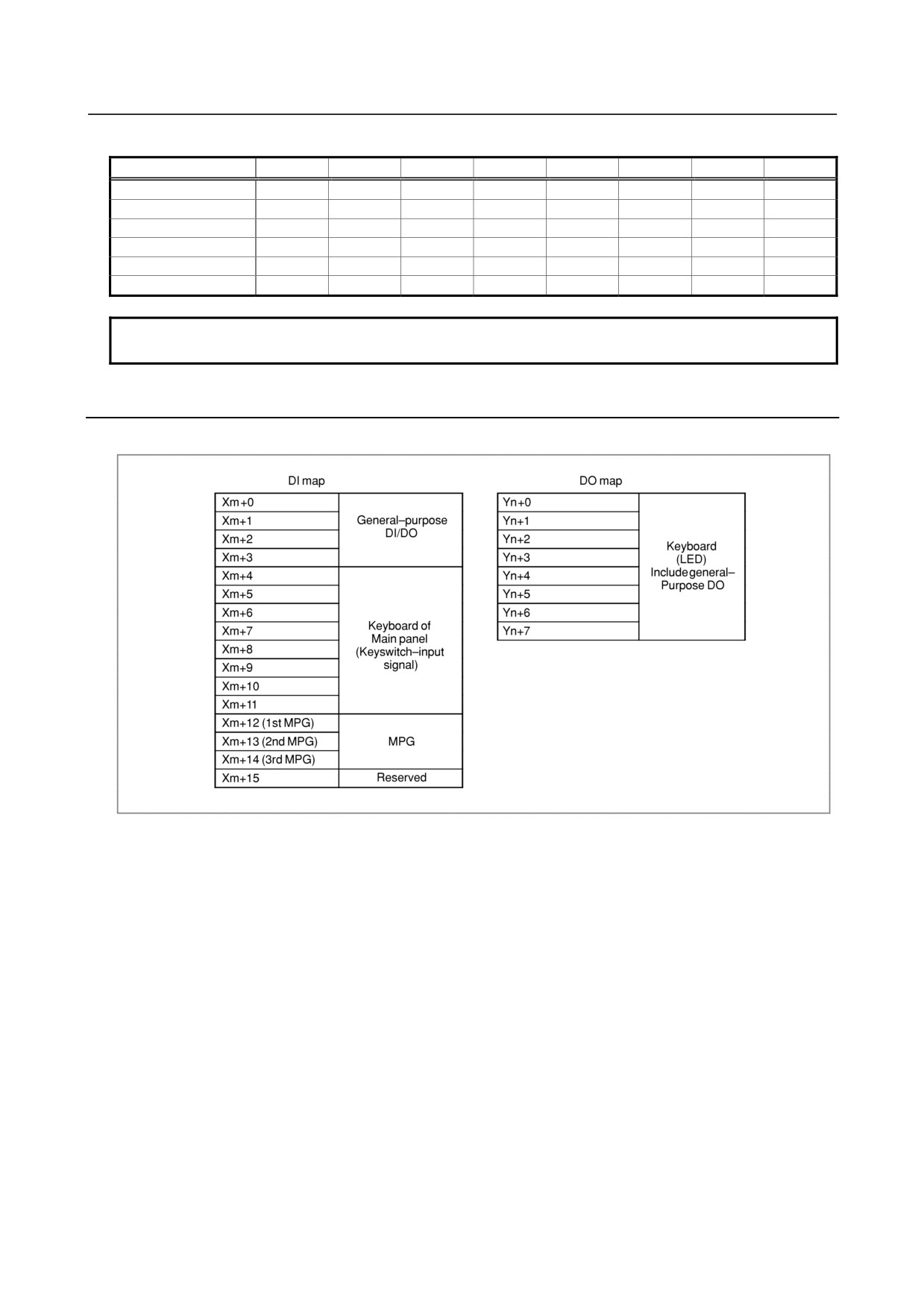
9.9.5
I/O Mapping
I/O address map is as follows.
DI mapping should be assigned 1 group = 16 byte mapping and DO mapping should be assigned 1 group
= 8 byte mapping. The reason is as follows.
MPG interface(the counter for MPG) uses Xm+12 to Xm+14 area and it is fixed. And if MPG interface
will be used, Xm+12 to Xm+14 area must be assigned. therefore, in case of 30i series and using MPG
interface, DI mapping must be assigned 16 byte mapping. MPG counter area are directly processed by
CNC software. So you must not use this area by customer ladder.
When the MPG interface is not used, its DI area may be assigned to another I/O group. I/O mapping of
the standard machine operator's panel can basically be assigned to any area of addresses. As for DI
mapping, however, there are fixed signals directly monitored by the CNC. The fixed signals cannot be
assigned to the keyswitch-input area. To use the fixed signals, therefore, assign them to an area other
than the keyswitch-input area.
- 251 -
9.CONNECTION OF I/O Link SLAVE DEVICES
B-64303EN/03
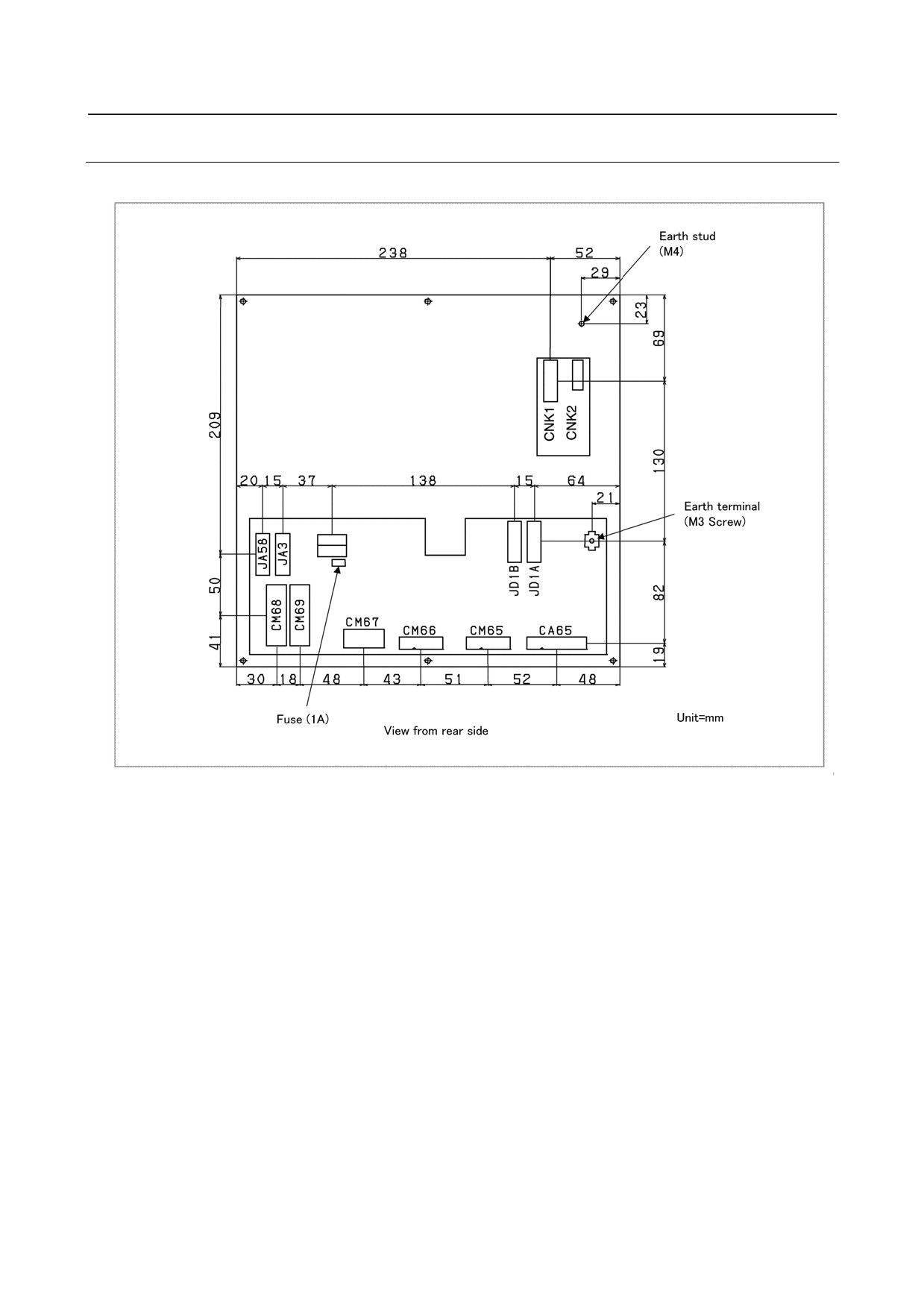
9.9.5.1 Connector locations of main panel
In case of main panel A
- 252 -
B-64303EN/03
9.CONNECTION OF I/O Link SLAVE DEVICES
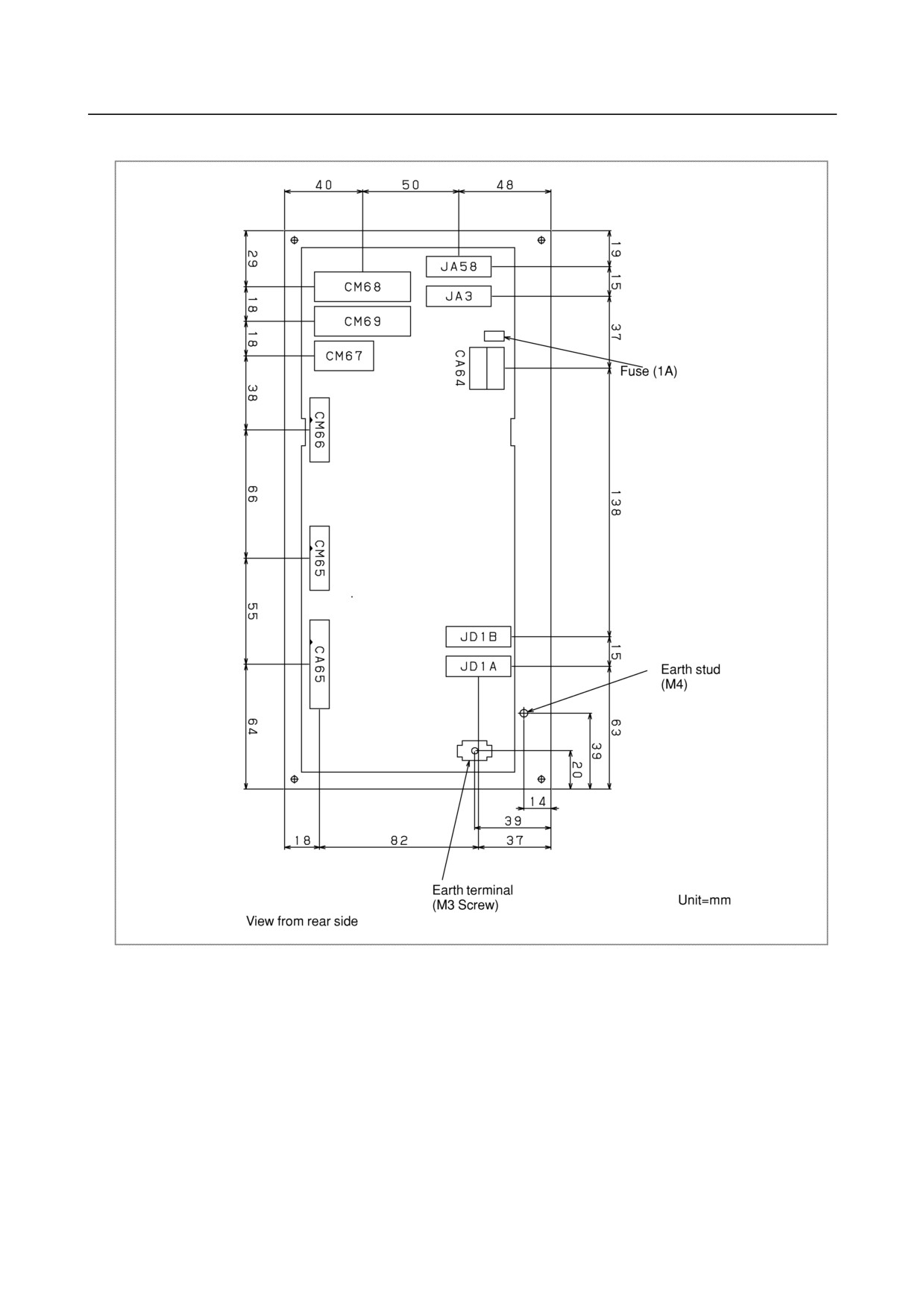
In case of main panel B
- 253 -
9.CONNECTION OF I/O Link SLAVE DEVICES
B-64303EN/03
9.9.6
Specifications
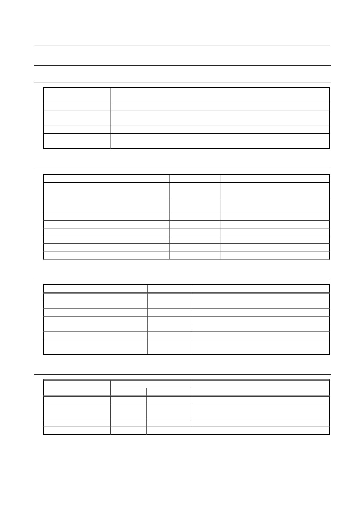
9.9.6.1 Environmental requirement
Temperature Around a
At operation
0°C to 55°C
unit
Storing or transporting
-20°C to 60°C
Temperature variance
Max.
1.1°C/min
Normally
75% or less (Relative humidity)
Humidity
Short time(Within one month)
95% or less (Relative humidity)
Vibration
Operating
0.5G or less
Normal FA atmosphere (Consult us when using the system under environments with
Atmosphere
higher degree of dust, coolant, or organic solution.)
9.9.6.2 Order specification
Name
Specification
Remark
Standard machine operators panel Main panel A
A02B-0319-C242
Keys with both symbol and English
characters/3-keystroke support model
Standard machine operators panel Main panel B
A02B-0319-C243
Keys with both symbol and English
characters/3-keystroke support model
Standard machine operators panel Sub panel A
A02B-0236-C232
Standard machine operators panel Sub panel B1
A02B-0236-C235
Set of transparent key tops
A02B-0236-K170
55 key tops
Set of blank key tops
A02B-0236-K171
55 key tops
Set of symbol English key tops
A02B-0236-K174
34 labeled key tops + 21 blank key tops
Fuse(Spare part)
A02B-0815-K001
1A
9.9.6.3 Main panel specification
Item
Specification
Remark
General-purpose DI points
32 points
24VDC type input
General-purpose DO points
8 points
24VDC type output
Keyswitches of MDI
65 keys
Full alphabet key (Main panel A)
Keyswitches of Machine operators panel
55 keys
Matrix DI
LED
Color : Green
Attached to all keyswitches, Matrix DO
MPG interface
Max. 3 units
Interface to CNC
FANUC I/O Link
Max. 16 modules or total points max. 1024/1024 will be
connection
available.
9.9.6.4 Sub panel A/B1 specification
Specification of Sub panel
Item
Remark
A
B1
Override rotary switch
2
2
5 bit Gray code output (with a parity bit)
Number of Contact : 4 (contact a × 2, contact b × 2)
Emergency stop switch
1
1
M3.5 Screw
Program protect key
1
1
ON/OFF switch
ON/OFF
-
- 254 -
B-64303EN/03
9.CONNECTION OF I/O Link SLAVE DEVICES
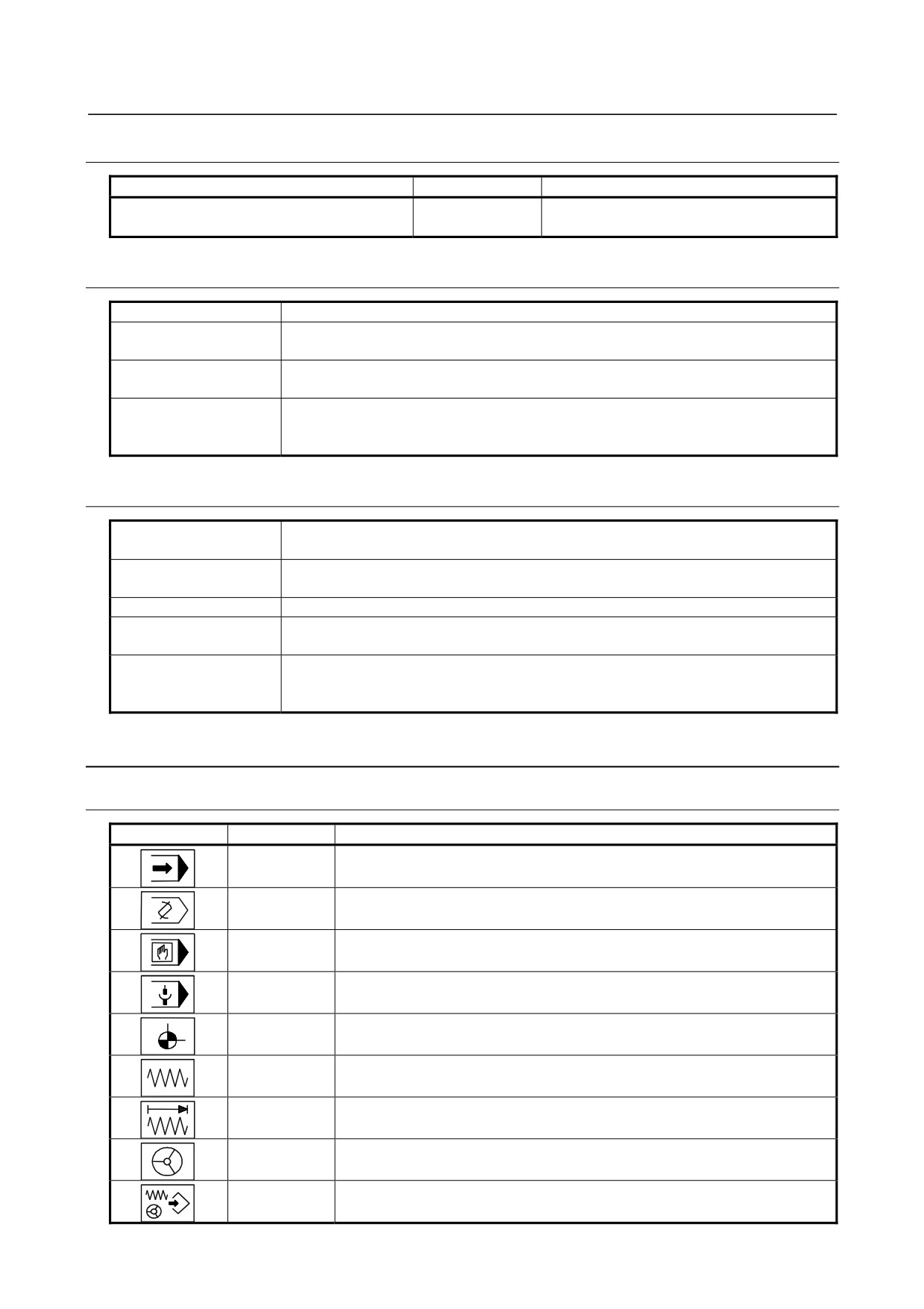
9.9.6.5 Power supply specification
Voltage
Capacity
Remark
24VDC±10% (from Power connector CA64,
0.4A
Including all DI consumption
including momentary values)
9.9.6.6 General-purpose DI signal definition
Capacity
30VDC, 16mA or more
Interconnect leakage
1mA or less(at 26.4V)
current in closed circuit
Interconnect voltage
2V or less(including the voltage drop in the cables)
drop in closed circuit
Receiver delay : Max. 2ms
Delay time
Need to consider about the serial communication (I/O Link) delay between CNC and
operators panel 2ms(MAX)+Scan cycle of ladder (Scan cycle is different each CNCs).
9.9.6.7 General-purpose DO signal definition
Maximum load current
200mA or less (including momentary values)
in ON state
Saturation voltage in
Max. 1V (When load current is 200mA)
ON state
Withstand voltage
24V±20% or less (including momentary values)
Leakage current in OFF
20μA or less
state
Driver delay : Max. 50μs
Delay time
Need to consider about the serial communication (I/O Link) delay between CNC and
operator's panel 2ms (MAX)+Scan cycle of ladder (Scan cycle is different each CNCs).
9.9.7
Key Symbol Indication on Machine Operator’s Panel
9.9.7.1 Meaning of key symbols
Symbol
English
Meaning of key
AUTO
AUTO mode selection signal; Sets automatic operation mode.
EDIT
EDIT mode selection signal; Sets program edit operation mode.
MDI
MDI mode selection; Sets MDI mode.
REMOTE
DNC operation mode; Sets DNC operation mode.
REF
Reference position return mode selection; Sets reference position return mode.
RETURN
JOG
JOG feed mode selection; Sets jog feed mode.
INC
Step feed mode selection; Sets step feed mode.
JOG
HANDLE Manual handle feed mode selection; Sets manual handle feed mode.
Teach-in jog
(reach-in handle) mode selection signal; Sets teach-in jog
TEACH
(teach-in handle) mode.
- 255 -
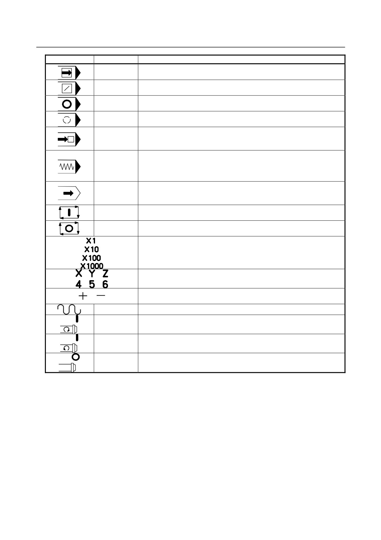
9.CONNECTION OF I/O Link SLAVE DEVICES
B-64303EN/03
Symbol
English
Meaning of key
SINGLE
Single block signal; Executes program one by one. This key is used to check
BLOCK
a program.
BLOCK
Block delete; Skips the execution of the blocks d ending with the end of block (;)
DELETE
when this button is pressed during automatic operation.
PRG
Program
stop(output only); Turns on the LED on the button when automatic
STOP
operation is stopped by M00 specified in the program.
OPT
Optional stop; Stops automatic operation after execution of the block of a
STOP
program where M01 is
specified in the program.
Program restart; A program may be restart at a block by specifying the
RESTART
sequence number of the block, after automatic operation is stopped because of
a broken tool or for holidays.
Dry run; Sets the axis feedrate to the jog feedrate instead of a programmed
DRY
feedrate when automatic operation is performed by setting this button to on.
RUN
This function is used to check only the movement of the tool when no
workpiece is mounted.
Machine lock; Updates only position display on the screen without making any
MC
axis movement, when automatic operation is performed by setting this button to
LOCK
on. This function is used to check a program.
CYCLE
Cycle start; Start automatic operation.
START
CYCLE
Cycle stop; Stops automatic operation.
STOP
Manual handle feed magnification:
Magnification for manual handle feed.
Magnified by 1, 10, 100, 1000.
Manual feed axis selection; Axes are selected, when these buttons are set to
on in the jog feed mode or step feed mode.
Manual feed operation; Performs movement along selected axes when these
buttons are set on in the jog feed mode or step feed mode.
TRVRS
Traverse; Performs jog feed at rapid traverse rate when this button is set to on.
SPDL
Positive spindle rotation direction; Rotates the spindle motor in the positive
CW
direction.
SPDL
Negative spindle rotation direction; Rotates the spindle motor in the negative
CCW
direction.
SPDL
Spindle stop; Stops the spindle motor rotation.
STOP
- 256 -