FANUC Series 0i-MODEL D, Series 0i Mate-MODEL D. CONNECTION MANUAL (HARDWARE) - page 6
B-64303EN/03
9.CONNECTION OF I/O Link SLAVE DEVICES
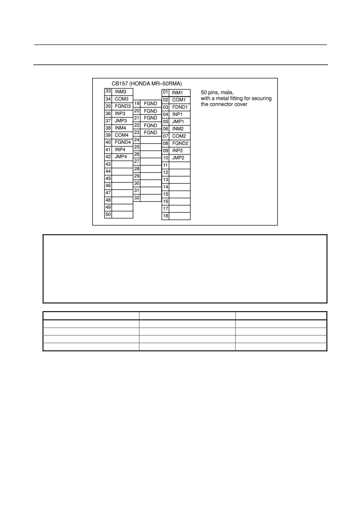
9.2.11 Analog Input Connector Pin Allocation
This section describes the analog input connector pin allocation of expansion module D.
NOTE
1 The DI/DO addresses of an expansion module and the DI/DO addresses of the
basic module are contiguous.
Addresses allocated to I/O Link are handled as a group covering the basic and
expansion modules. That is, when the first addresses allocated are X0004 and
Y0000 (m = 4, n = 0), the DI/DO addresses are as listed below.
2 With the analog input module, the DO space is also used as an input channel
selection area.
DI
DO
Basic module
X4 to X6
Y0 to Y1
Basic module 1
X7 to X9
Y2 to Y3
Basic module 2
X10 to X12
Y4 to Y5
Basic module 3
X13 to X15
Y6 to Y7
- 137 -
9.CONNECTION OF I/O Link SLAVE DEVICES
B-64303EN/03
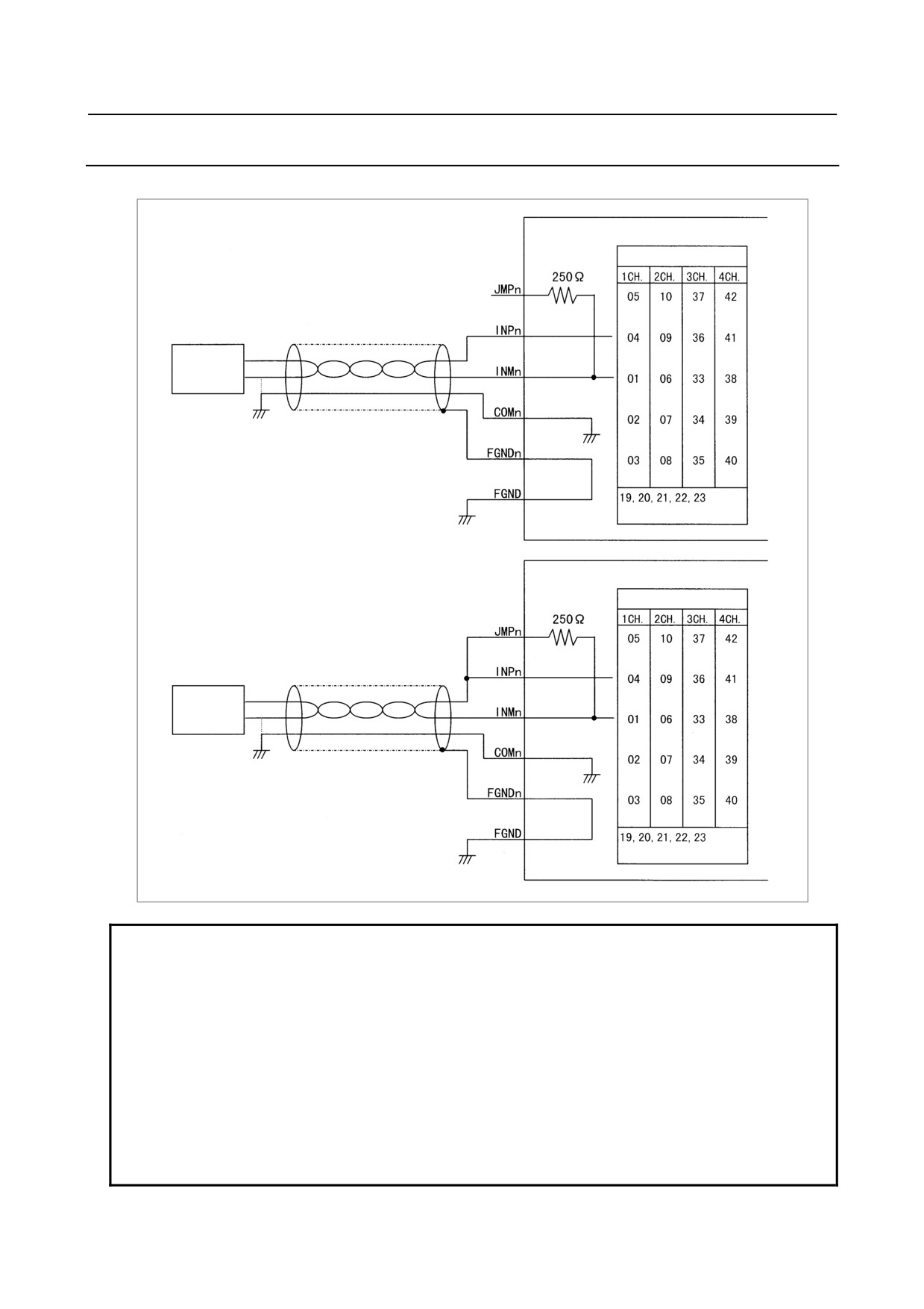
9.2.12 Analog Input Signal Connections
This section provides a diagram of the analog input connector connections of expansion module D.
Analog input module
Pin number
Not connected
For voltage input
Voltage
source
(Common to all channels)
Analog input module
DO turned off in the
sequence
Pin number
For current input
Current
source¹
(Common to all channels)
NOTE
1 In the diagram above, n represents each channel (n = 1, 2, 3, 4).
2 Current input or voltage input can be selected on a channel-by-channel basis.
For current input, connect JMPn to INPn.
3 For the connection, use a shielded twisted pair.
4 In the diagram above, the shield of each channel is connected to FGNDn, and
FGND is used for shield processing of all channels. However, the shield of a
channel may be directly connected to frame ground with a cable clamp, instead
of using FGNDn.
5 If the voltage (current) source has a GND pin, as shown in the figure above,
connect COMn to this pin. Otherwise, connect INMn and COMn together in the
analog input module.
- 138 -
B-64303EN/03
9.CONNECTION OF I/O Link SLAVE DEVICES
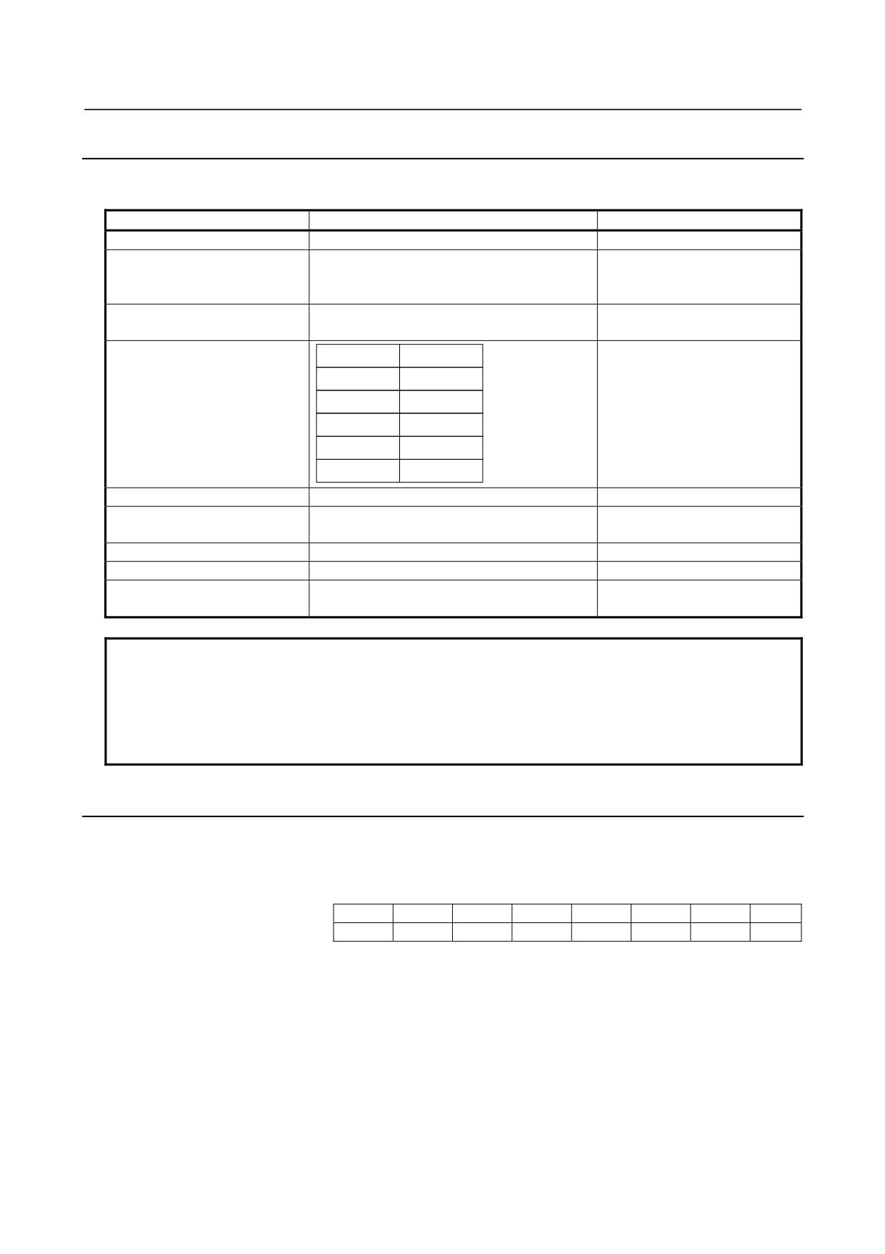
9.2.13 Analog Input Signal Specifications
This section describes the specifications of the analog input signals used with expansion module D.
Item
Specifications
Remarks
Number of input channels (Note)
Four channels
Analog input
DC-10 to +10V (Input resistance: 4.7 MΩ)
Voltage input or current input
DC-20 to +20mA (Input resistance: 250 Ω)
can be selected on
channel-by-channel basis.
Digital output (Note)
12 bits (binary)
Represented as two’s
complement
Input/output correspondence
Analog input
Digital output
+10V
+2000
+5V or +20mA
+1000
0V or 0mA
0
-5V or -20mA
-1000
-10V
-2000
Resolution
5 mV or 20 µA
Overall precision
Voltage input: ±0.5%
With respect to full scale
Current input: ±1%
Maximum input voltage/current
±15V/±30mA
Minimum conversion time (Note)
Ladder scan period of CNC connected
Number of occupied input/output
DI = 3 bytes, DO = 2 bytes
points (Note)
NOTE
This analog input module has four input channels. The digital output section
consists of a group of 12 bits within the three-byte occupied input points. This
means that the channel to be used can be dynamically selected by the ladder.
The channel switching DO point for channel selection is included in the two-byte
occupied output points.
9.2.14 Analog Input Specifications
(Digital output)
This digital input module has four input channels. The digital output section consists of a group of 12 bits
within the three-byte occupied input points. The output format is indicated below.
Address in the module
7
6
5
4
3
2
1
0
Xm(even-numbered address)
D07
D06
D05
D04
D03
D02
D01
D00
Xm+1(odd-numbered address)
0
0
CHB
CHA
D11
D10
D09
D08
D00 to D11 represent 12-bit digital output data. D00 and D11 correspond to weightings of 20 and 211,
respectively.
D11 is a sign bit expressed as a two’s complement. CHA and CHB represent analog input channels.
This means that when the two bytes above are read with a PMC program, the A-D converted data of the
CHA and CHB input channels can be read from D11 to D00. For CHA and CHB, see the description of
channel selection, below.
When data is read with a PMC program, some notes need to be observed. See "(Address allocation)" on
the next page.
- 139 -
9.CONNECTION OF I/O Link SLAVE DEVICES
B-64303EN/03
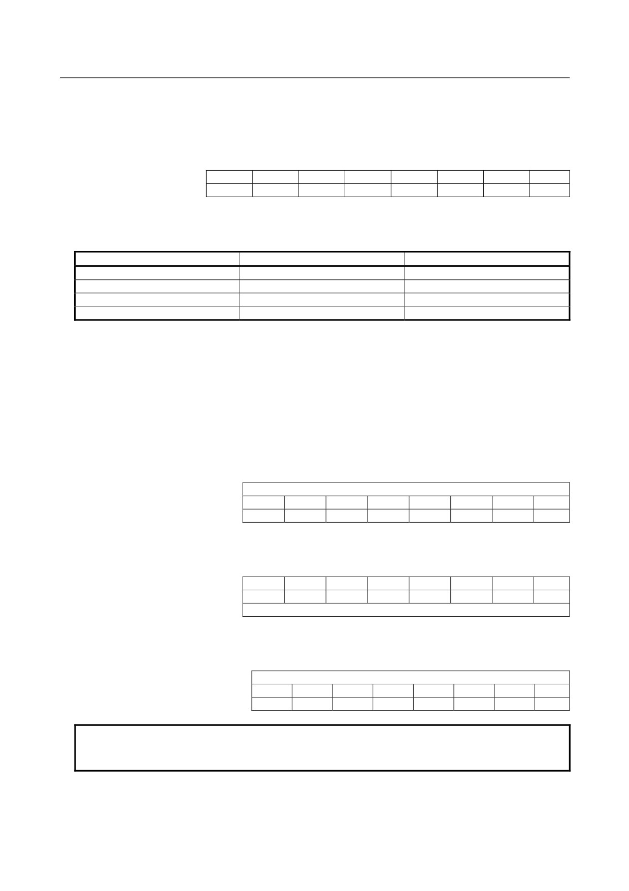
(Channel selection)
With this analog input module, which of the four channels is to be output to the digital output section
must be determined with a PMC program.
The DO points used for this selection are CHA and CHB (two-byte occupied output points). These are
mapped as indicated below.
Address in the module
7
6
5
4
3
2
1
0
Yn
X
X
X
X
X
X
X
X
Yn+1
X
X
X
X
X
X
CHB
CHA
By writing the values indicated below to CHA and CHB, the corresponding channel is selected, and the
A-D converted data of the channel and the data of the selected channel can be read as DI data. The
character X indicated above represents an unused bit, so that either 1 or 0 may be written in place of X.
CHB
CHA
Channel selected
0
0
Channel 1
0
1
Channel 2
1
0
Channel 3
1
1
Channel 4
Immediately after channel switching, some time is required until the channel is switched to the selected
one and A-D converted data is enabled. Be sure to confirm the channel before obtaining A-D converted
data.
(Address allocation)
The start address of X (DI) of the basic modules including the analog input module must always be
allocated at an even-numbered address. With this allocation, the digital output addresses of the analog
input module are as described below, depending on where the analog input module is allocated
• When the analog input module is allocated in the space for expansion module 1 (m represents the
allocation start address.)
Address in the module
7
6
5
4
3
2
1
0
Xm+3(odd-numbered address)
Undefined
Xm+4(even-numbered address)
D07
D06
D05
D04
D03
D02
D01
D00
Xm+5(odd-numbered address)
0
0
CHB
CHA
D11
D10
D09
D08
• When the analog input module is allocated in the space for expansion module 2 (m represents the
allocation start address.)
Address in the module
7
6
5
4
3
2
1
0
Xm+6(even-numbered address)
D07
D06
D05
D04
D03
D02
D01
D00
Xm+7(odd-numbered address)
0
0
CHB
CHA
D11
D10
D09
D08
Xm+8(even-numbered address)
Undefined
• When the analog input module is allocated in the space for expansion module 3 (m represents the
allocation start address.)
Address in the module
7
6
5
4
3
2
1
0
Xm+9(odd-numbered address)
Undefined
Xm+10(even-numbered address)
D07
D06
D05
D04
D03
D02
D01
D00
Xm+11(odd-numbered address)
0
0
CHB
CHA
D11
D10
D09
D08
NOTE
When two-byte digital output addresses are to be referenced with a PMC
program, a read must always be performed word-by-word (16 bits).
- 140 -
B-64303EN/03
9.CONNECTION OF I/O Link SLAVE DEVICES
9.2.15 Manual Pulse Generator Connection
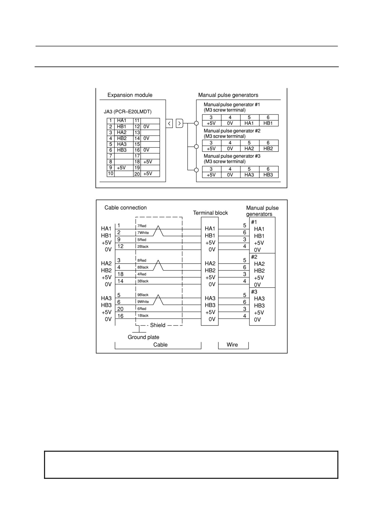
An example in which three manual pulse generators are connected to expansion module A is shown
below.
Recommended wire material:
A66L-0001-0286 (#20AWG×6+#24AWG×3 pairs)
Recommended connector:
A02B-0120-K303 (including the following connector and case)
(Connector: Hirose Electric Co., Ltd. FI40-2015S, soldering type)
(Case: Hirose Electric Co., Ltd. FI40-20-CV5)
Recommended cables:
A02B-0120-K841 (7m) (for connecting three manual pulse generators)
A02B-0120-K848 (7m) (for connecting two manual pulse generators)
A02B-0120-K847 (7m) (for connecting one manual pulse generator)
(These cables do not include the wire shown in the above figure.)
NOTE
The number of connectable manual pulse generators depends on the type and
option configuration.
- 141 -
9.CONNECTION OF I/O Link SLAVE DEVICES
B-64303EN/03
9.2.16 Cable Length for Manual Pulse Generator
Like a pulse coder, the manual pulse generator operates on 5 VDC. The supply voltage drop due to the
cable resistance must be held below 0.2 V (when those of the 0-volt and 5-volt wires are combined), as
expressed in the following expression:
0.1×R×2L
Where 0.1 : Manual pulse generator supply current [0.1 A]
0.2≥
m
R : Resistance per unit cable length [μ/m]
m : Number of 0-volt and 5-volt wires
L
: Cable length [m].
m
L≤
R
Therefore, the cable length can be determined using the following expression.
In the case of the A66L-0001-0286 cable, for example, when three pairs of signal wires and six power
supply wires (20/0.18, 0.0394 Ω/m) are used (three power supply wires connected to 5 V and the other
three to 0 V), the cable length is:
3
L≤
=76.75[m]
0.0394
However, the maximum pulse transmission distance for the manual pulse generator is 50 m. Taking this
into consideration, the cable length may be extended to:
38.37 m (when two generators are used), or
25.58 m (when three generators are used).
9.2.17 Connection of Basic and Expansion Modules
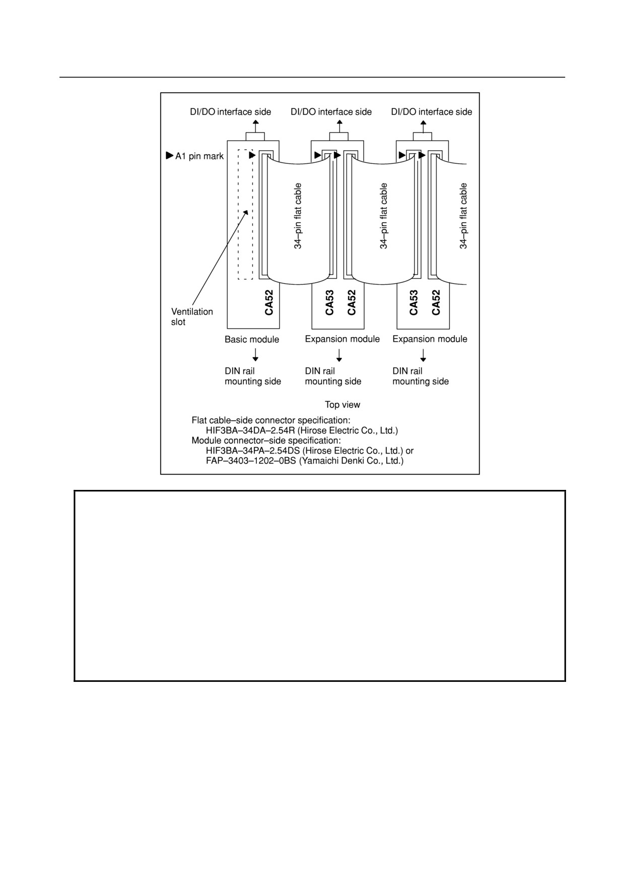
Modules can be connected in the same way, regardless of whether you are connecting the basic module to
an expansion module or connecting two expansion modules. Connect the modules by using 34-pin flat
cable connectors as shown in the figure below. Ensure that all 34 pins at one end of the cable are
connected to the corresponding pins at the other end;
e.g., connect the A1 pin to the pin having the same designation (A1) at the other end.
- 142 -
B-64303EN/03
9.CONNECTION OF I/O Link SLAVE DEVICES
NOTE
Modules need to be spaced at least 32 mm apart, in which case a flat cable of
about 20 mm in length is required. To install modules further away from each
other, the cable length will be 20 mm plus the extra distance. Note that the
maximum length of a flat cable is 300 mm. To ensure adequate ventilation,
install the modules in such a way that the flat cables lie on top of them. The
basic module has a vent at the top (as indicated by the dotted lines in the above
figure). When connecting modules, install expansion modules so that the flat
cables do not cover the vent, as shown in the above figure.
Therefore, for direct connection to the connection printed circuit board,
expansion modules are installed to the right of the basic module on the
installation plane. For installation using DIN rails or screws, expansion modules
are installed to the left of the basic module on the installation plane.
- 143 -
9.CONNECTION OF I/O Link SLAVE DEVICES
B-64303EN/03
9.2.18 Module Installation
When connecting a connector panel printed circuit board directly
(external module view and mounting diagram)
Dimensions of connector panel
printed circuit board: ±0.2
Board thickness: 1.6 mm
Square hole
No.1 pin
Note)
Square hole
I/O Link
interface
I/O interface
MPG interface
(for expansion module)
JD1A JD1B
Connector panel printed circuit board connector specification:
HONDA MRH-50FD (50-pin female straight connector without fitting)
NOTE
1 A connector with a fitting (HONDA MRH-50RMA) is used for the module-side
I/O interface.
Always use a connector having no fitting for the connector panel printed circuit
board.
2 Area where pattern printing is prohibited
: Prohibited area on component side
: Prohibited area on soldered side
- 144 -
B-64303EN/03
9.CONNECTION OF I/O Link SLAVE DEVICES
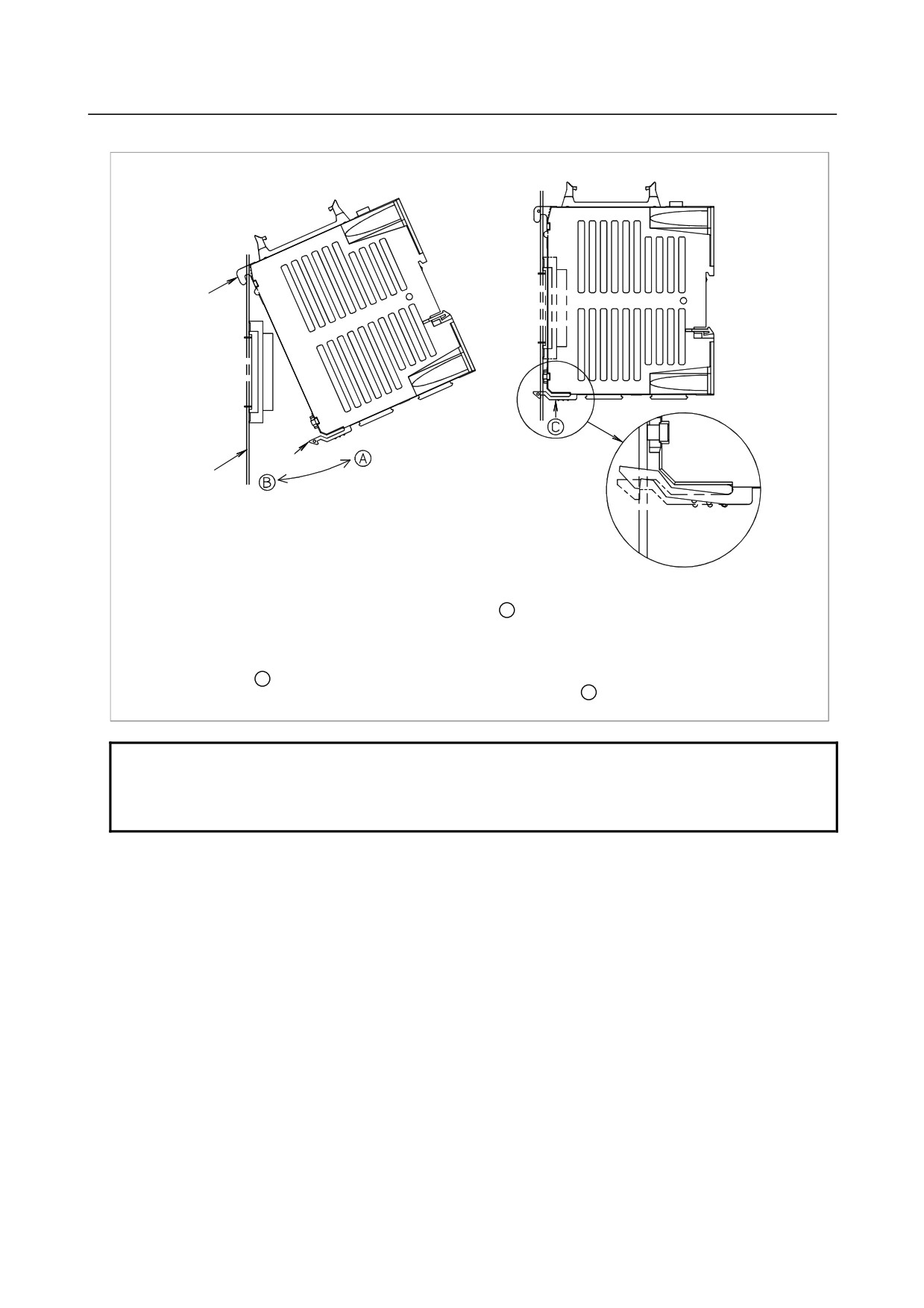
When connecting a connector panel printed circuit board directly (mounting and dismounting a module)
Hook
Stopper
Connector panel
printed circuit
board
Mounting the module
1. Insert the hook of the module into the square hole located at the upper part of the connector panel printed circuit board.
2. Using the hook as a fulcrum, push the module in the direction of B , and attach the module’s connector to the connector on
the printed circuit board.
3. Push the stopper into the lower hole of the printed circuit board until it clicks into place.
Dismounting the module
1. Press the stopper C upward.
2. Using the hook as a fulcrum, pull the lower part of the module in the direction of A .
NOTE
When mounting and dismounting a module, hold the module by its top and
bottom surfaces.
Avoid applying force to the sides where there are slits.
- 145 -
9.CONNECTION OF I/O Link SLAVE DEVICES
B-64303EN/03
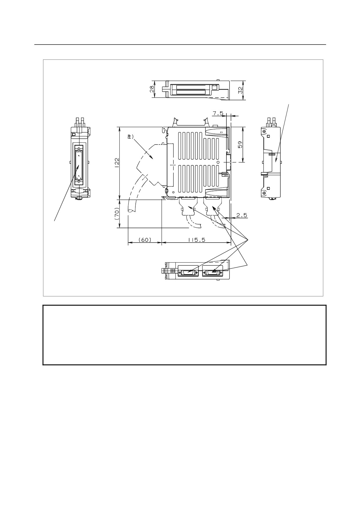
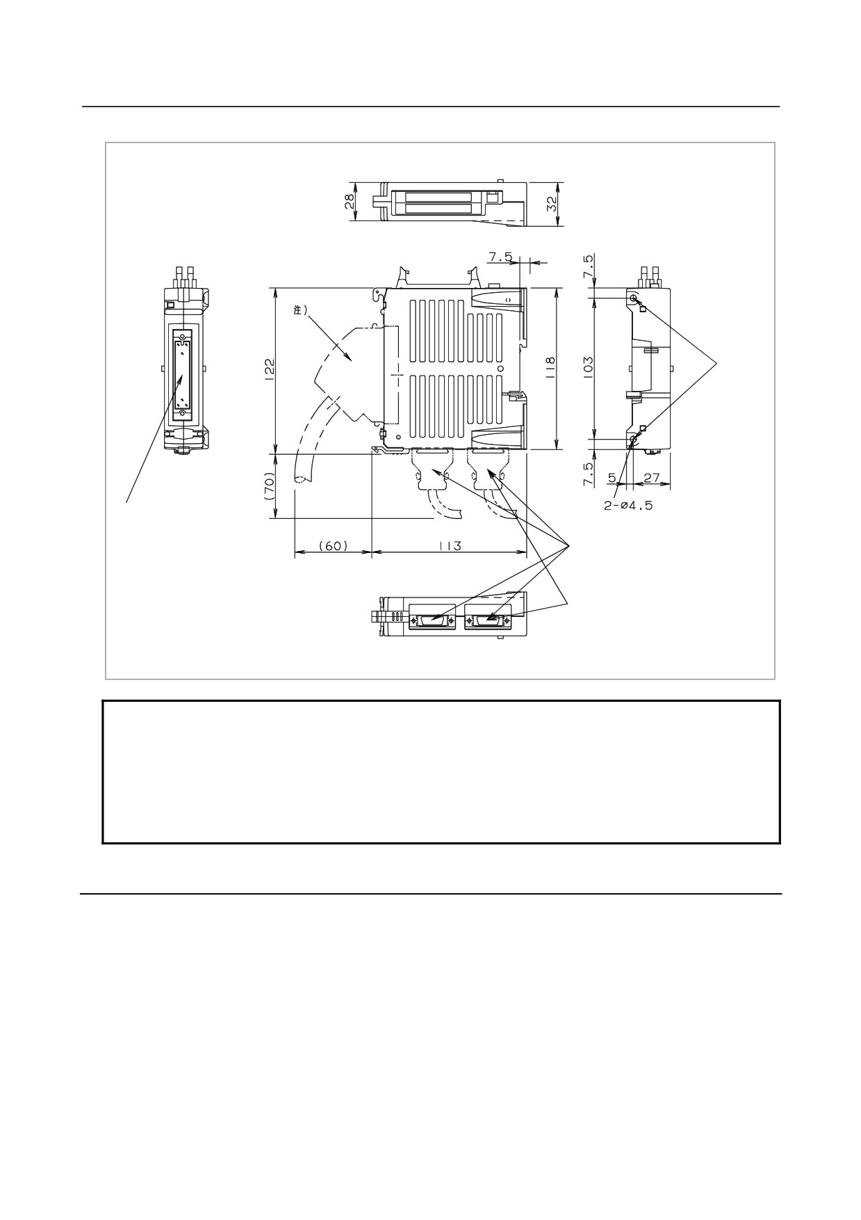
When mounting a DIN rail (external module view and mounting diagram)
Mount the DIN rail here.
I/O interface
I/O Link interface
MPG interface
(for expansion module)
NOTE
Recommended connector:
A02B-0098-K891 (including the following connector and case)
(Connector: HONDA MR-50FH solder type)
(Case: HONDA MR-50NSB angled type)
Recommended wire material:
A66L-0001-0042 (7/0.18, 50 pins)
- 146 -
B-64303EN/03
9.CONNECTION OF I/O Link SLAVE DEVICES
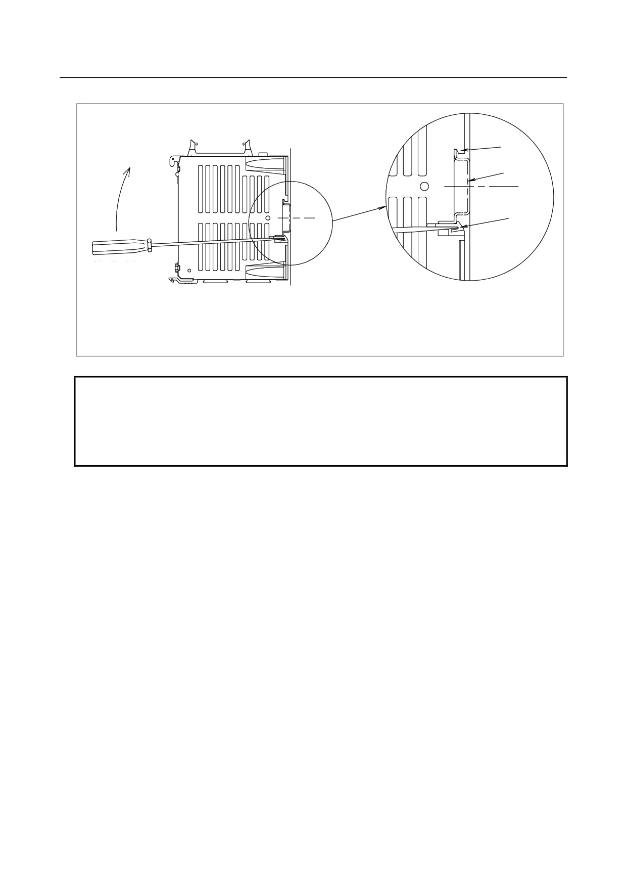
When mounting a DIN rail (mounting and dismounting a module)
Hook
DIN rail
Stopper
Mounting the module
1. Hook the module at the upper end of the DIN rail.
2. Push the stopper into the slit located at the lower end of the rail until it clicks into place.
Dismounting the module
1. Insert the tip of the slotted screwdriver and push out the stopper in the direction
indicated by the arrow.
NOTE
When dismounting the module, take care not to damage the stopper by applying
excessive force with the screwdriver.
When mounting and dismounting a module, hold the module by its top and
bottom surfaces.
Avoid applying force to the sides where there are slits.
- 147 -
9.CONNECTION OF I/O Link SLAVE DEVICES
B-64303EN/03
When mounting a module using screws (external module view and mounting diagram)
Screw
holes
I/O interface
I/O Link interface
MPG interface
(for expansion module)
JD1A
JD1B
NOTE
Recommended connector:
A02B-0098-K891 (including the following connector and case)
(Connector: HONDA MR-50FH solder type)
(Case: HONDA MR-50NSB angled type)
Recommended wire material:
A66L-0001-0042 (7/0.18, 50 pins)
9.2.19 Other Notes
DO signal reaction to a system alarm
There is a possibility that the I/O module will not operate normally due to a failure of CNC or I/O Link
slave module, or abnormally power supply voltage. To prevent accidents even in this case, design the
machine to operate safely by making a safety circuit outside the I/O module.
The circuit of this I/O module is designed so that all DO signals are turned off if a system alarm is
occurred in the CNC which controls the I/O module, or if a power of the CNC or the I/O module is turned
off. However, it cannot be guaranteed that DO signals of the I/O module will certainly be turned off.
Therefore, manage signals related to safety by making a safety circuit outside this I/O module.
- 148 -
B-64303EN/03
9.CONNECTION OF I/O Link SLAVE DEVICES
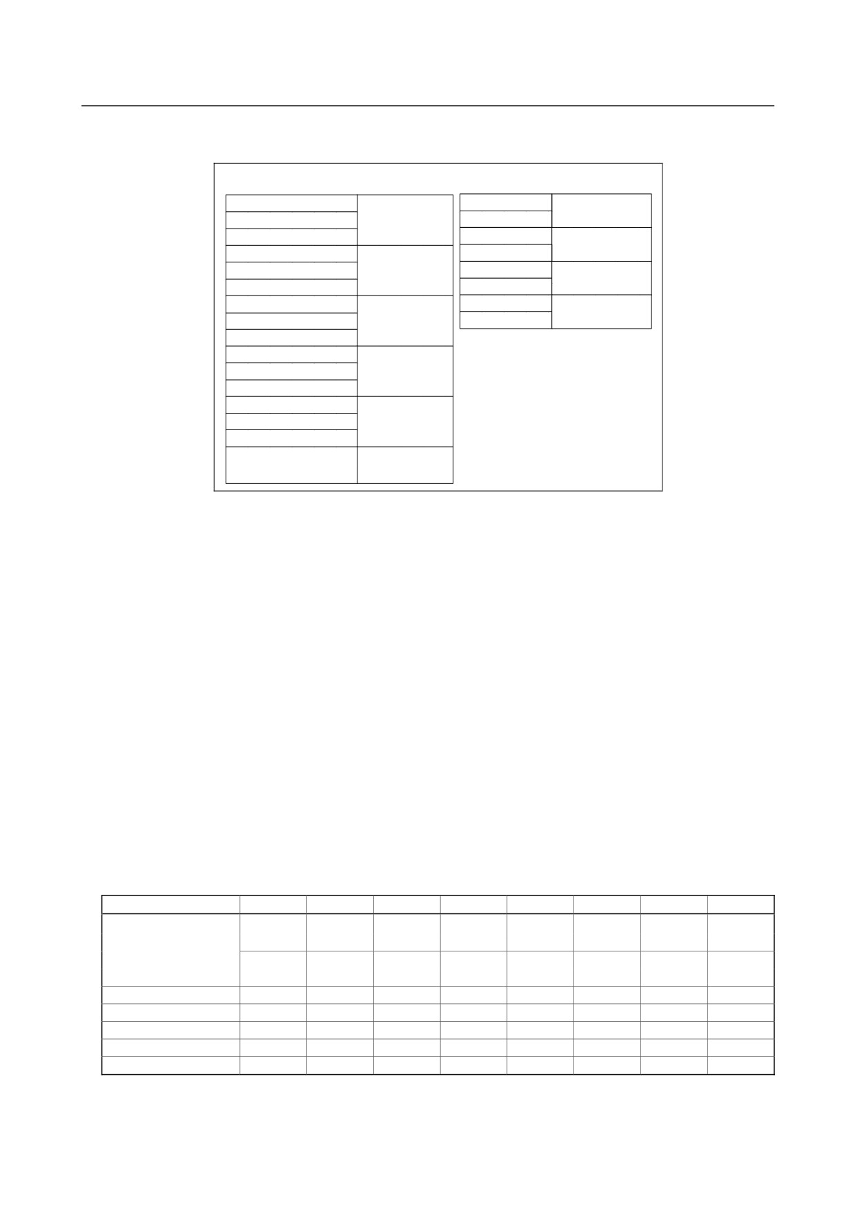
Address allocation
For the connector panel I/O module, I/O addresses are mapped as follows.
DI space map
DO space map
Xm
Yn
Basic module
Basic module
Xm+1
Yn+1
Xm+2
Yn+2
Expansion
Xm+3
Yn+3
module 1
Expansion
Xm+4
Yn+4
Expansion
module 1
module 2
Xm+5
Yn+5
Xm+6
Yn+6
Expansion
Expansion
module 3
Xm+7
Yn+7
module 2
Xm+8
Xm+9
Expansion
Xm+10
module 3
Xm+11
Xm+12(for 1st MPG)
Expansion
Xm+13(for 2nd MPG)
module 1
Xm+14(for 3rd MPG)
Xm+15(DO alarm
Basic module
detection)
The basic connector panel I/O module is allocated a group of DI addresses (16 bytes) and a group of DO
addresses (8 bytes). Up to three hardware expansion modules can be added or removed as required.
The reason for this address allocation is explained below.
The MPG interface (MPG counter) occupies a DI space from Xm+12 through Xm+14. These addresses
are fixed regardless of whether expansion module 2 or 3 is used, and Xm+12 through Xm+14 must be
allocated as a DI work area to enable the use of the MPG. Therefore, when using an MPG for the i
series CNC, allocate DI addresses in units of 16 bytes. Do not use the DI space from Xm+12 through
Xm+14 for Ladder; the CNC processes the MPG counter value directly.
DI address Xm+15 is used for detecting overcurrent and overheating alarms that occur in the IC used in
the DO driver.
[For details, see the section describing the detection of DO (output signal) alarms.]
This address is fixed regardless of whether expansion module 2 or 3 is used, and it must be allocated as a
work area before it can be used. When using this area, therefore, allocate DI addresses in units of 16
bytes.
Basically, I/O addresses can be allocated to the connector panel I/O modules freely. When allocating DI
addresses, however, consider also the addresses that are directly supervised by the CNC, and keep the
following in mind.
Fixed addresses directly supervised by the CNC (Example: Series 0i)
7
6
5
4
3
2
1
0
X0004
SKIP
ESKIP
-MIT2
+MIT2
-MIT1
+MIT1
XAE2
XAE1
SKIP6
SKIP5
SKIP4
SKIP3
SKIP2
SKIP8
SKIP7
SKIP
ESKIP
SKIP5
SKIP4
SKIP3
XAE3
XAE2
XAE1
SKIP6
SKIP2
SKIP8
SKIP7
X0005
X0006
X0007
X0008
*ESP
X0009
*DEC5
*DEC4
*DEC3
*DEC2
*DEC1
The upper row indicates the T series (first path), and the lower row indicates the M series.
- 149 -
9.CONNECTION OF I/O Link SLAVE DEVICES
B-64303EN/03
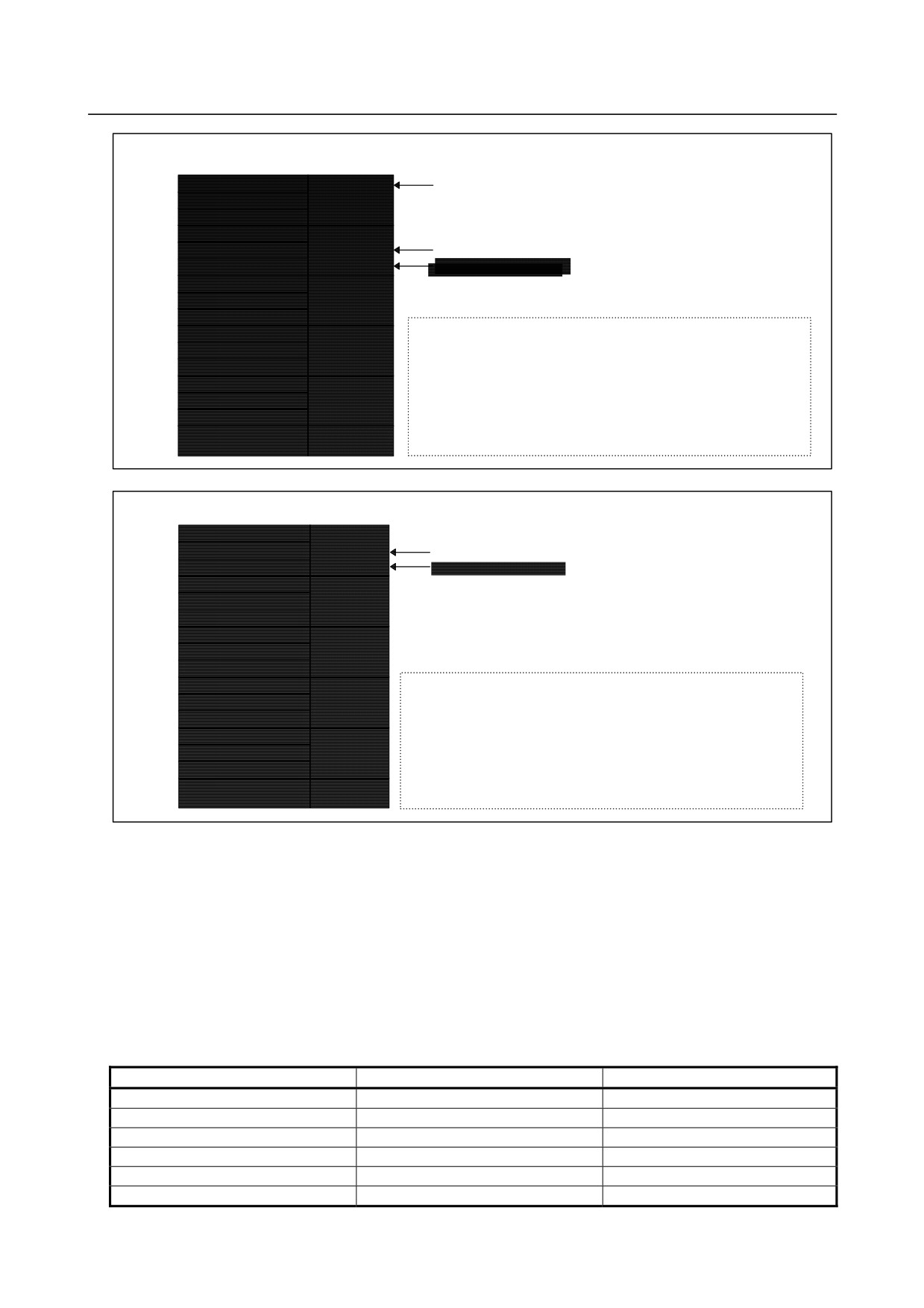
When DI addresses are allocated in units of 16 bytes, starting at X0004
X0004
SKIPn and other fixed signals
X0005
Basic module
X0006
X0007
Expansion
X0008
*ESP fixed signal
module 1
X0009
*DECn fixed signal
X0010
Expansion
X0011
module 2
X0012
X0013
Expansion
The minimum configuration consists of the basic module and
X0014
module 3
expansion module 1. Expansion modules 2 and 3 may be
X0015
added as required. This allows fixed signals, such as SKIPn
X0016 (for 1st MPG)
and *DECn, to always be used and the *ESP fixed signal to be
Expansion
allocated to an address for which the common voltage is fixed to
X0017 (for 2nd MPG)
module 1
24 V. Also, with the i series CNC, the MPG interface provided
X0018 (for 3rd MPG)
by expansion module 1 can always be used.
X0019
Basic module
(DO alarm detection)
When DI addresses are allocated in units of 16 bytes, starting at X0007
X0007
X0008
Basic module
*ESP fixed signal
X0009
*DECn fixed signal
X0010
Expansion
X0011
module 1
X0012
X0013
Expansion
X0014
module 2
X0015
X0016
The minimum configuration consists of the basic module only.
Expansion
X0017
module 3
Expansion modules 1, 2, and 3 may be added as required. In
the minimum configuration, SKIP and other fixed signals and the
X0018
MGP interface of expansion module 1 cannot be used. In this
X0019 (for 1st MPG)
Expansion
case, however, the *DECn fixed signal can always be used and
X0020 (for 2nd MPG)
module 1
the *ESP fixed signal can be allocated to an address for which
X0021 (for 3rd MPG)
the common voltage is fixed to 24 V in the minimum
configuration.
X0022
Basic module
(DO alarm detection)
DO (output signal) alarm detection
The DO driver of the Basic and Expansion module A/B is capable of detecting an overcurrent and
measuring its own temperature. If an accident, such as the connecting of the cable to ground, causes an
abnormal increase in the load current or in the driver temperature, a protection circuit, which is provided
for each DO driver (1 byte), is activated and keeps the DO signal for the relevant 1 byte in the OFF state
until the cause of the problem is eliminated. Even if this occurs, the CNC and I/O module continue
operating. The DI address (Xm+15) identifies the DO driver which has detected the alarm. The table
below shows the correspondence between the DI address (Xm+15) bits and the DO addresses. Bit value
"1" indicates that the corresponding DO driver has detected an alarm. The contents of the Xm+15 area
can be checked by using the DGN screen of the CNC or by performing alarm processing for the area in
advance by using Ladder. This helps alarm detection and recovery.
Alarm detection address and bit
DO address
Location
Xm+15.0
Yn+0
Basic module
Xm+15.1
Yn+1
Basic module
Xm+15.2
Yn+2
Expansion module 1
Xm+15.3
Yn+3
Expansion module 1
Xm+15.4
Yn+4
Expansion module 2
Xm+15.5
Yn+5
Expansion module 2
- 150 -
B-64303EN/03
9.CONNECTION OF I/O Link SLAVE DEVICES
Alarm detection address and bit
DO address
Location
Xm+15.6
Yn+6
Expansion module 3
Xm+15.7
Yn+7
Expansion module 3
NOTE
This function is not supported by the 2A output module or analog input module.
Allocation of the 2A output module and analog input module
The 2A output module and analog input module can be allocated to any of the spaces for expansion
modules 1, 2, and 3. When an MPG interface is required, the module occupies the space for expansion
module 1; no 2A output module or analog input module can be allocated in the space for expansion
module 1.
The 2A output module does not involve DI points, so that the DI area of the space in which a 2A output
module is allocated is unusable. When a 2A output module is allocated to the space for expansion
module 2, for example, the areas from Xm+6 to Xm+8 cannot be used.
(The spaces for the other
modules are not shifted. In this case, the DI space of expansion module 3 remains at Xm+9 through
Xm+11.)
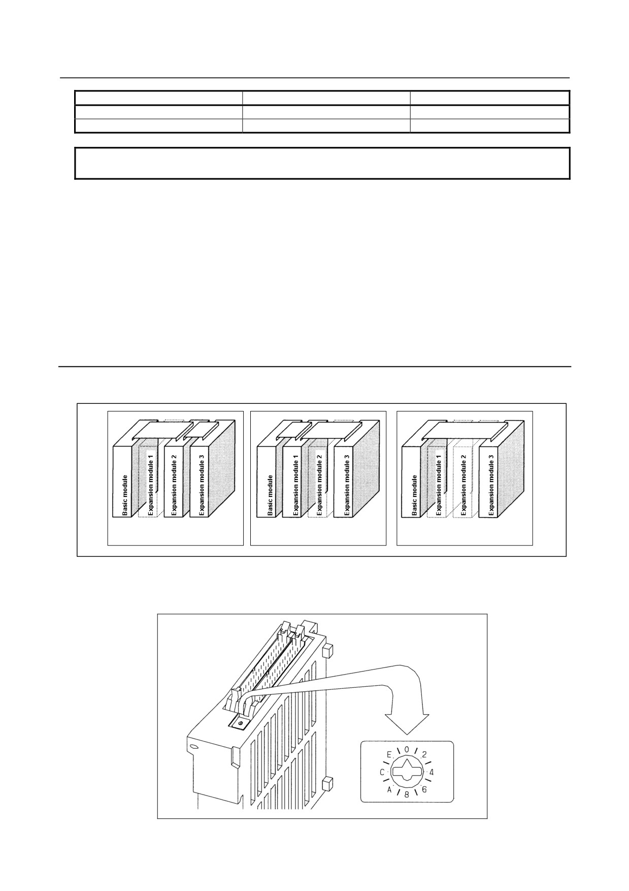
9.2.20 Distribution I/O Setting
By changing the setting (rotary switch) for the expansion modules, connections can be made by omitting
some expansion modules as shown below.
Expansion module 1 is
Expansion module 2 is
Expansion modules 1 and 2 are
omitted.
omitted.
omitted.
Method of setting (control and method of setting the control)
As shown below, the control (rotary switch) is located on an expansion module. To change the setting,
turn the switch with a flat-bladed screwdriver with a tip width of about 2.5 mm.
- 151 -
9.CONNECTION OF I/O Link SLAVE DEVICES
B-64303EN/03
Each setting position of the rotary switch has the following meaning:
Setting
Actual indication
Meaning of setting
position
0
0
This is the standard setting. The rotary switch is factory-set to this position.
This setting is used when no expansion module is omitted.
1
-
Set the rotary switch on an expansion module to this position when the
preceding expansion module is omitted.
2
2
Set the rotary switch on an expansion module to this position when the
preceding two expansion modules are omitted.
3
-
This setting is prohibited.
4 to F
4, -, 6, -,
4, 8, or C has the same effect as 0.
8, -, A, -,
5, 9, or D has the same effect as 1.
C, -, E, -,
6, A, or E has the same effect as 2.
7, B, or F has the same effect as 3.
(This setting, however, is prohibited.)
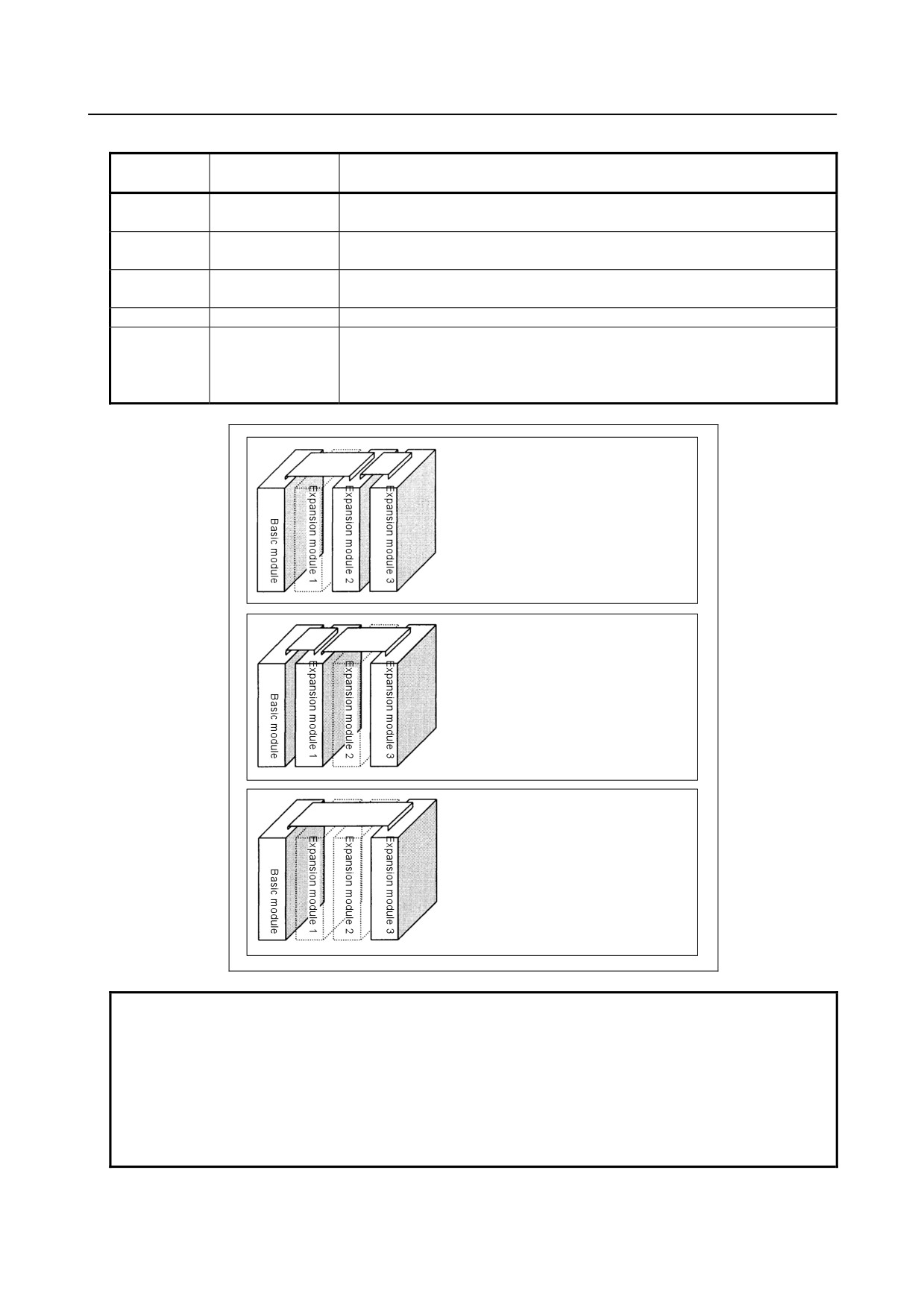
(When expansion module 1 is omitted)
On expansion module 2, set the rotary
switch to setting position 1. On
expansion module 3, keep the rotary
switch set to setting position 0.
(When expansion module 2 is omitted)
On expansion module 3, set the rotary
switch to setting position 1. On
expansion module 1, keep the rotary
switch set to setting position 0.
(When expansion modules 1 and 2 are
omitted)
On expansion module 3, set the rotary
switch to setting position 2.
NOTE
1 Expansion module A (DI/DO = 24/16, with manual pulse interface)
(A03B-0815-C002) is fitted with an additional rotary switch as other types of
modules are modified. However, expansion module A is always mounted at the
location of expansion module 1, so that its factory setting need not be changed.
2 This setting is a function that was added newly.
This function is not provided in the expansion models shipped in August 1998 or
earlier.
- 152 -
B-64303EN/03
9.CONNECTION OF I/O Link SLAVE DEVICES
9.3
CONNECTION OF OPERATOR'S PANEL I/O MODULE
(FOR MATRIX INPUT)
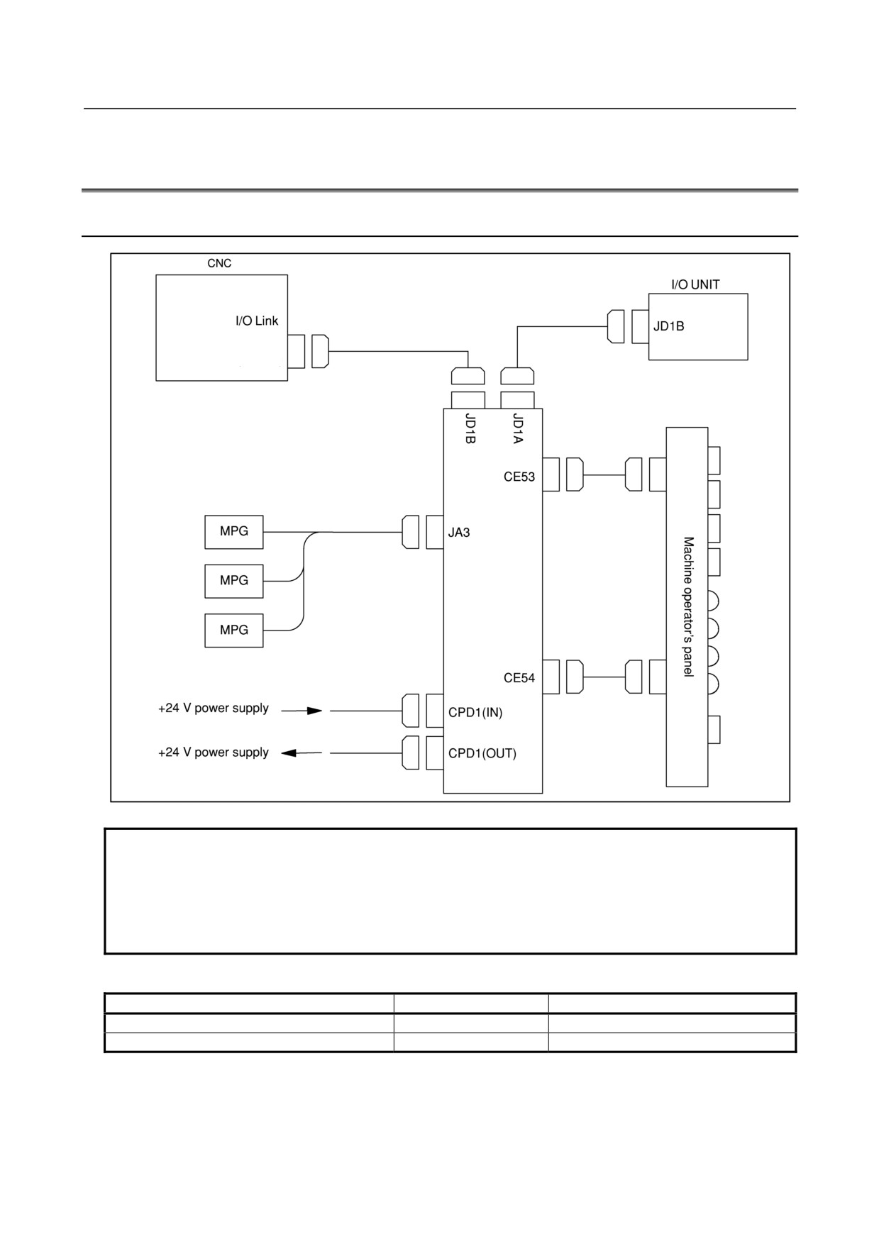
9.3.1
Overall Connection Diagram
JD51A
NOTE
When the operator's panel I/O module is used together with a unit (connector
panel I/O module) connected to the I/O Link supporting another MPG interface,
only the MPG interface of the unit (module) closest to the CNC connected to the
I/O Link is enabled. The following screw type connectors cannot be used to
connect the I/O Link or MPG.
Connectors that cannot be used on the cable side
Specification
Manufacturer
Connector case
FI-20-CV7
Hirose Electric Co., Ltd.
Connector case and connector
FI30-20S-CV7
Hirose Electric Co., Ltd.
- 153 -
9.CONNECTION OF I/O Link SLAVE DEVICES
B-64303EN/03
9.3.2
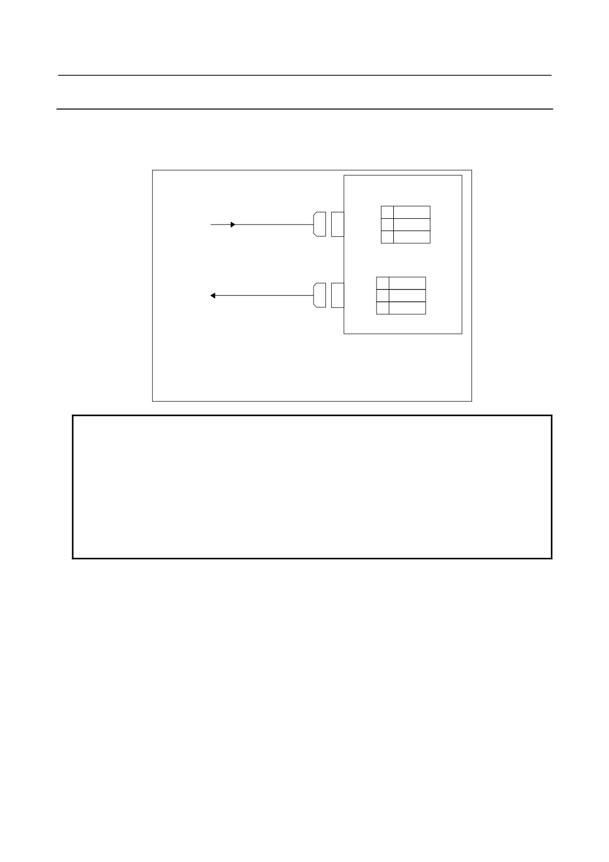
Power Connection
Provide the CPD1 (IN) connector, shown below, with the power necessary for printed circuit board
operation and that for DI operation. To facilitate power division, the power is output to CPD1 (OUT)
exactly as it is input from CPD1 (IN). When power division is required, use CPD1 (OUT).
Up to 1.0 A can be supplied by branching.
CPD1(IN)
01
+24V
24 V power
02
0V
supply
03
CPD1(OUT)
01
+24V
24 V power
02
0V
supply
03
Recommended cable-side connector:
A02B-0120-K324
(including the following connector housing and case)
(Housing: Japan AMP 1-178288-3)
(Contacts: Japan AMP 1-175218-5)
NOTE
The specification of the power supply connector CPD1 (IN) is the same as that
for CPD1 (OUT). There are no indications on the printed circuit board to
distinguish between the IN and OUT connectors. Do not turn off the +24 V
supply to the connector during operation. Turning off the +24 V supply will
cause a CNC communication alarm. When turning on the power, the +24 V
supply to the I/O module must be turned on before or at the same time as the
power supply to the CNC. When turning off the power, the +24 V supply to the
I/O module must be turned off after or at the same time as the power supply to
the CNC.
- 154 -
B-64303EN/03
9.CONNECTION OF I/O Link SLAVE DEVICES
9.3.3
DI/DO Connector Pin Arrangement
CE53
CE54
A
B
A
B
01
0V
0V
01
0V
0V
02
N.C.
+24V
02
COM1
+24V
03
Xm+0.0
Xm+0.1
03
Xm+1.0
Xm+1.1
04
Xm+0.2
Xm+0.3
04
Xm+1.2
Xm+1.3
05
Xm+0.4
Xm+0.5
05
Xm+1.4
Xm+1.5
06
Xm+0.6
Xm+0.7
06
Xm+1.6
Xm+1.7
07
Yn+0.0
Yn+0.1
07
Yn+3.0
Yn+3.1
08
Yn+0.2
Yn+0.3
08
Yn+3.2
Yn+3.3
09
Yn+0.4
Yn+0.5
09
Yn+3.4
Yn+3.5
10
Yn+0.6
Yn+0.7
10
Yn+3.6
Yn+3.7
11
Yn+1.0
Yn+1.1
11
Yn+4.0
Yn+4.1
12
Yn+1.2
Yn+1.3
12
Yn+4.2
Yn+4.3
13
Yn+1.4
Yn+1.5
13
Yn+4.4
Yn+4.5
14
Yn+1.6
Yn+1.7
14
Yn+4.6
Yn+4.7
15
Yn+2.0
Yn+2.1
15
Yn+5.0
Yn+5.1
16
Yn+2.2
Yn+2.3
16
Yn+5.2
Yn+5.3
17
Yn+2.4
Yn+2.5
17
Yn+5.4
Yn+5.5
18
Yn+2.6
Yn+2.7
18
Yn+5.6
Yn+5.7
19
KYD0
KYD1
19
Yn+6.0
Yn+6.1
20
KYD2
KYD3
20
Yn+6.2
Yn+6.3
21
KYD4
KYD5
21
Yn+6.4
Yn+6.5
22
KYD6
KYD7
22
Yn+6.6
Yn+6.7
23
KCM1
KCM2
23
KCM5
KCM6
24
KCM3
KCM4
24
KCM7
DOCOM
25
DOCOM
DOCOM
25
DOCOM
DOCOM
Flat cable-side connector specification:
A02B-0120-K342
(HIFBB-50D-2.54R (Hirose Electric Co., Ltd.))
50 contacts
Cable material specification:
A02B-0120-K886
(61-meter, 50-pin cable (Hitachi Cable, Ltd. or Oki Electric Cable Co., Ltd.))
NOTE
An output DC voltage of +24 V at CE53 (B02) and CE54 (B02) is for DI signals.
Do not supply 24 VDC to these pins from the outside.
- 155 -
9.CONNECTION OF I/O Link SLAVE DEVICES
B-64303EN/03
9.3.4
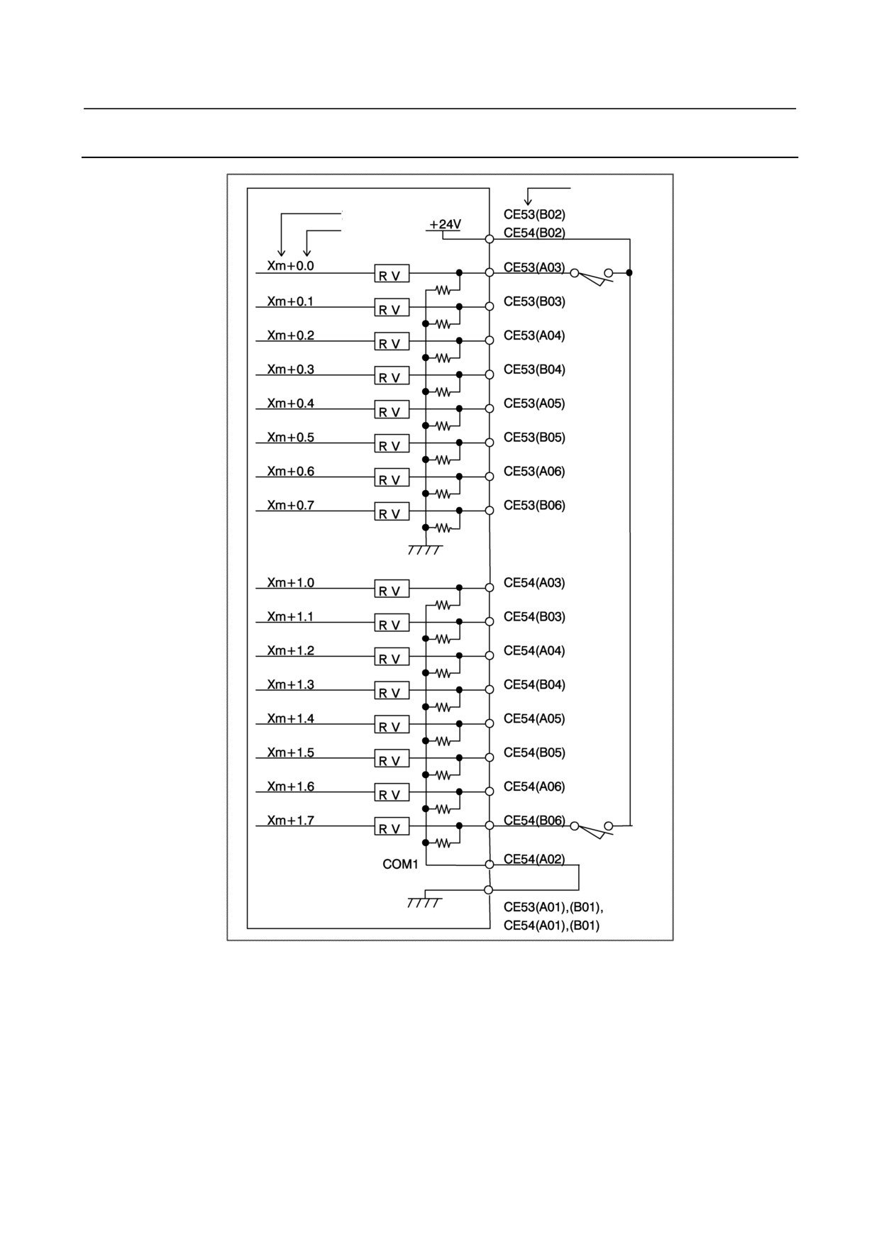
DI (General-purpose Input Signal) Connection
Pin No.
Address No.
Bit No.
- 156 -
B-64303EN/03
9.CONNECTION OF I/O Link SLAVE DEVICES
NOTE
1 Xm+1.0 through Xm+1.7 are DI pins for which a common voltage can be
selected. That is, by connecting the COM1 CE54(A02) pin to the +24 V power
supply, a DI signal can be input with its logical state reversed. If, however, a
cable is connected to ground, it has the same effect as inputting an ON state DI
signal. To prevent this from occurring, the connection of the COM1 CE54(A02)
pin to the 0 V power supply is recommended whereever possible.
For safety reasons, the emergency stop signal needs to be allocated to an
appropriate bit of the addresses for which the common voltage is fixed, ranging
from Xm+0.0 to Xm+0.7. See "Address allocation" in Section 8.5.10 for details
of how to allocate the emergency stop signal.
For unused DI pins allocated to the addresses for which the common voltage is
fixed (from Xm+0.0 to Xm+0.7), the logic is fixed to "0". For unused pins
allocated to Xm+1.0 to Xm+1.7 for which the common voltage can be selected,
the logic is fixed to "0" when the COM1 CE54(A02) pin is connected to the 0 V
power supply. When the COM1 CE54(A02) pin is connected to the +24 V
power supply, the logic is fixed to "1". The logic of the unused pins allocated to
Xm+1.0 to Xm+1.7 is variable when the contact of the COM1 CE54(A02) pin is
open.
2 An output DC voltage of +24 V at CE53 (B02) and CE54 (B02) is for DI signals.
Do not supply 24 VDC to these pins from the outside.
9.3.5
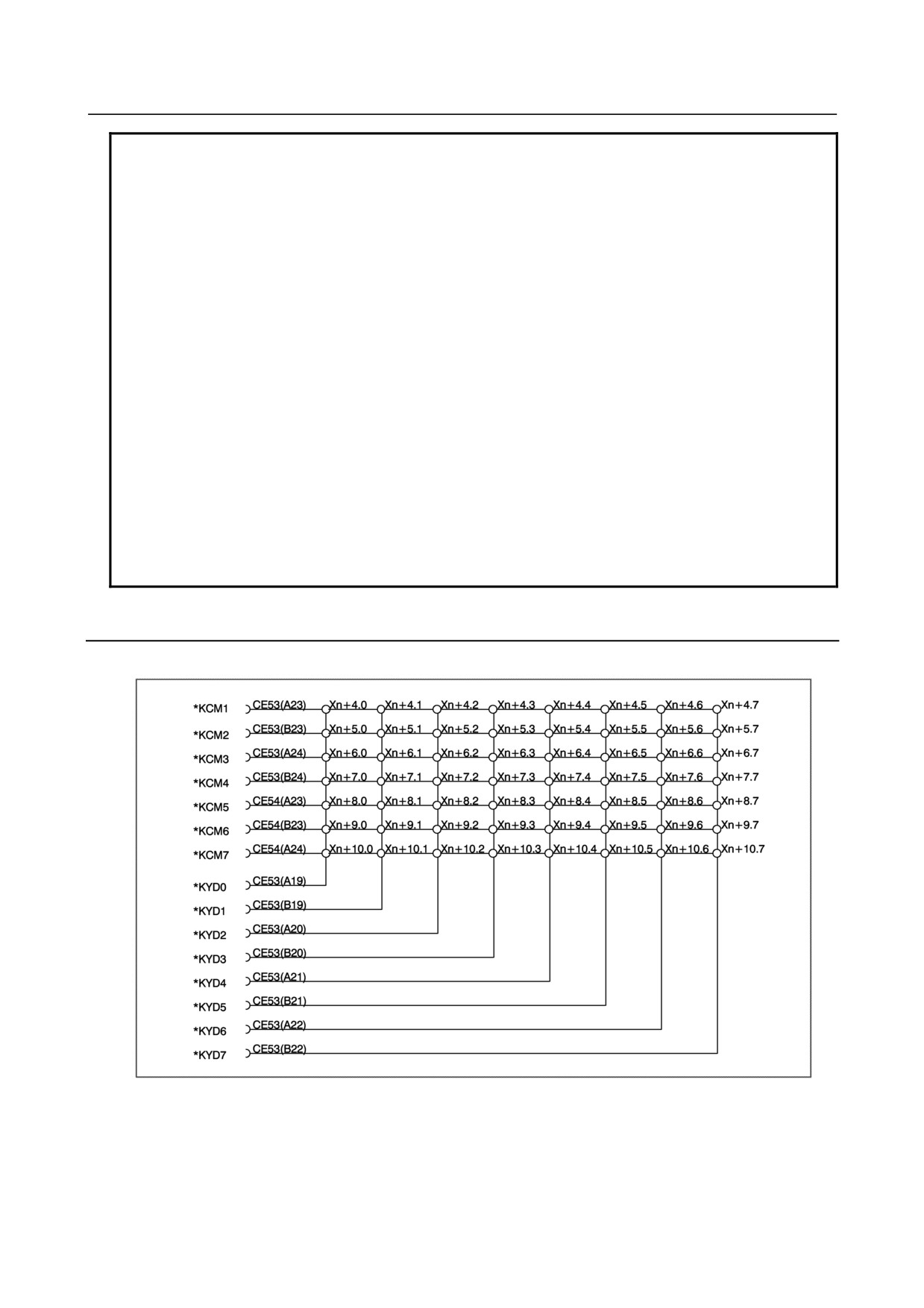
DI (Matrix Input Signal) Connection
○ A maximum of 56 points are provided.
- 157 -
9.CONNECTION OF I/O Link SLAVE DEVICES
B-64303EN/03
NOTE
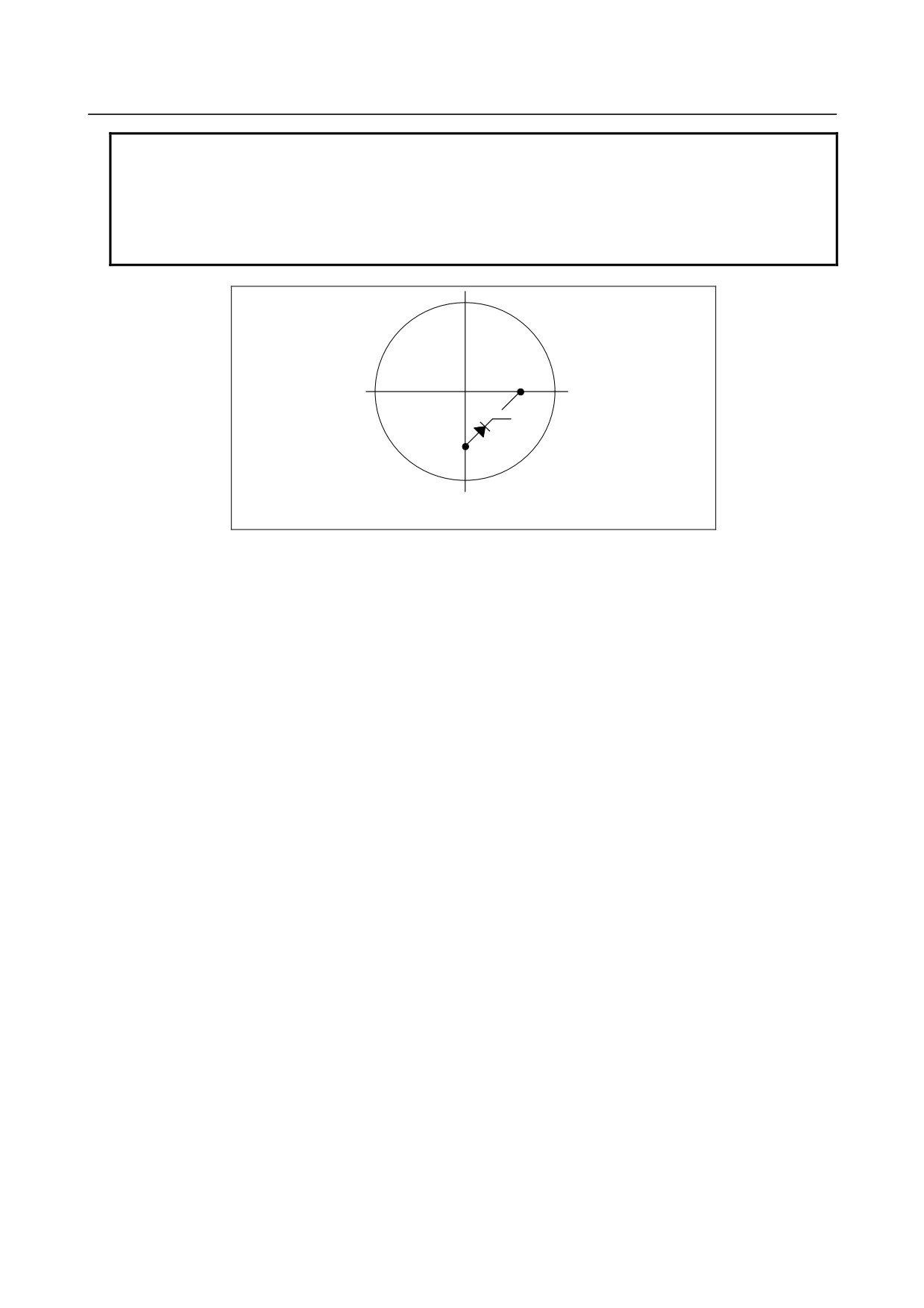
1 Detour prevention diodes must be incorporated for matrix signal input, as shown
in the following figure. Otherwise, only two signals can be input at the same
time. Inputting three or more signals simultaneously without using detour
prevention diodes may result in data input errors.
2 A cable for matrix input signals must be 150 mm or less in length.
*KCMn
*KYDn
- 158 -
B-64303EN/03
9.CONNECTION OF I/O Link SLAVE DEVICES
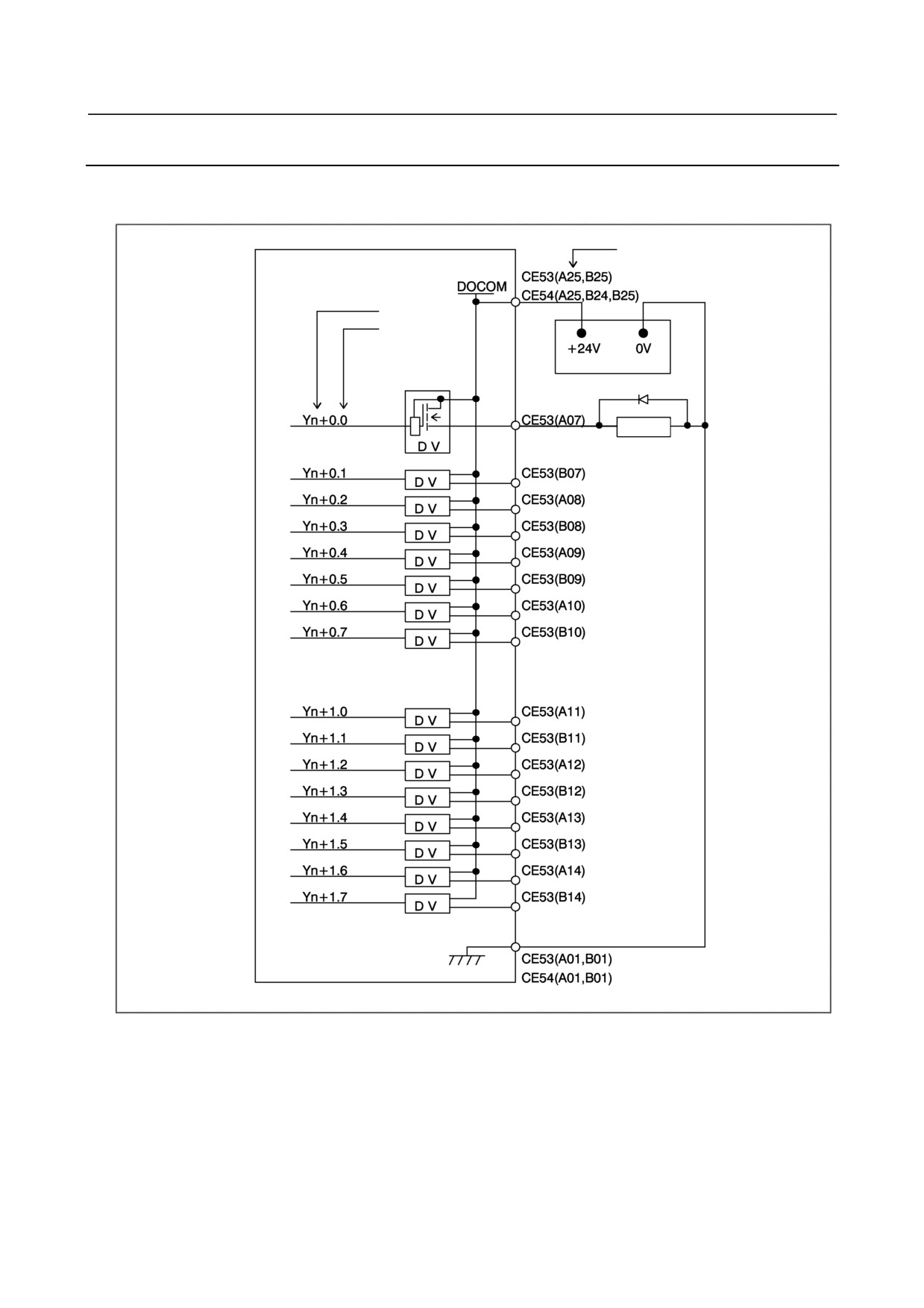
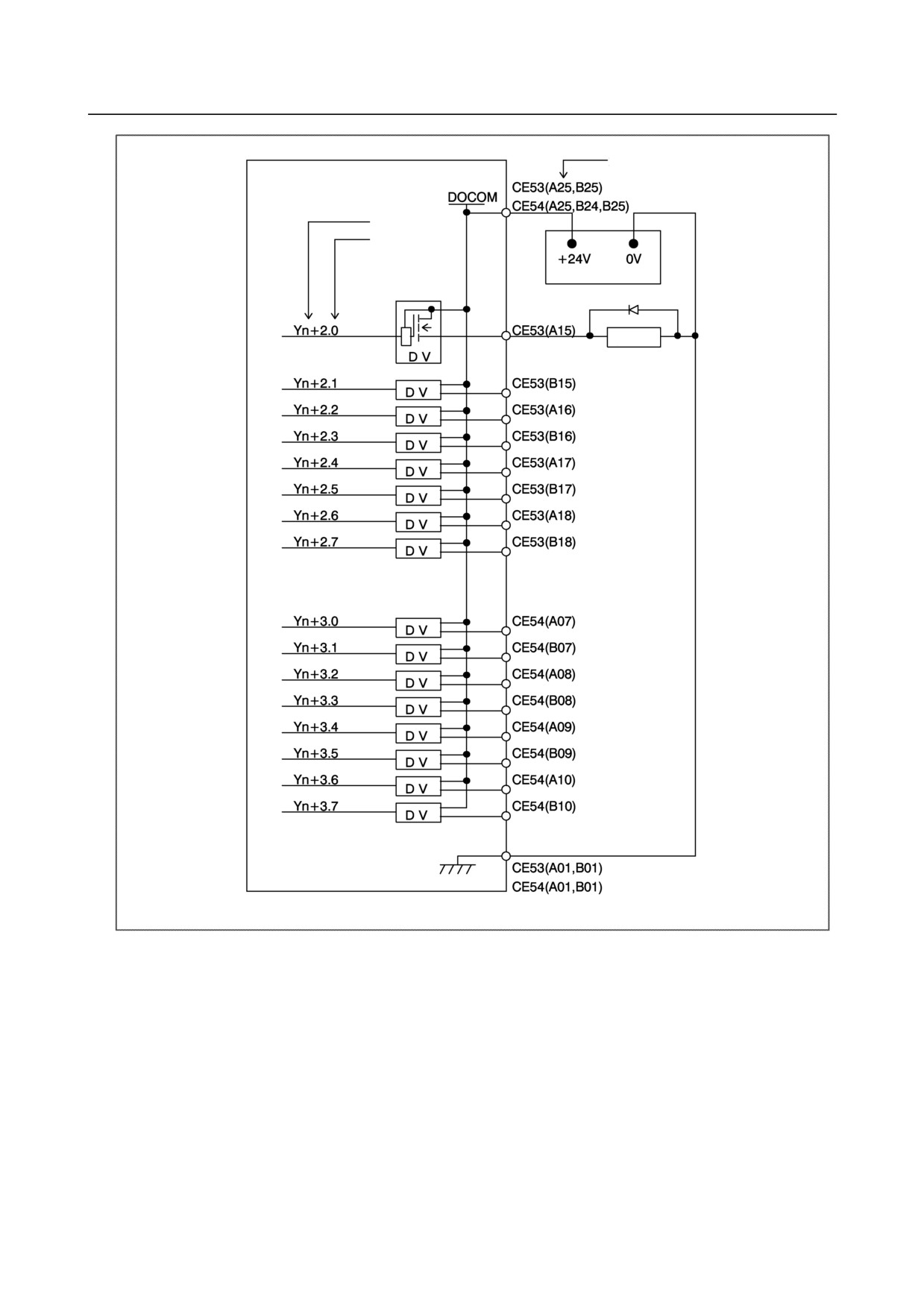
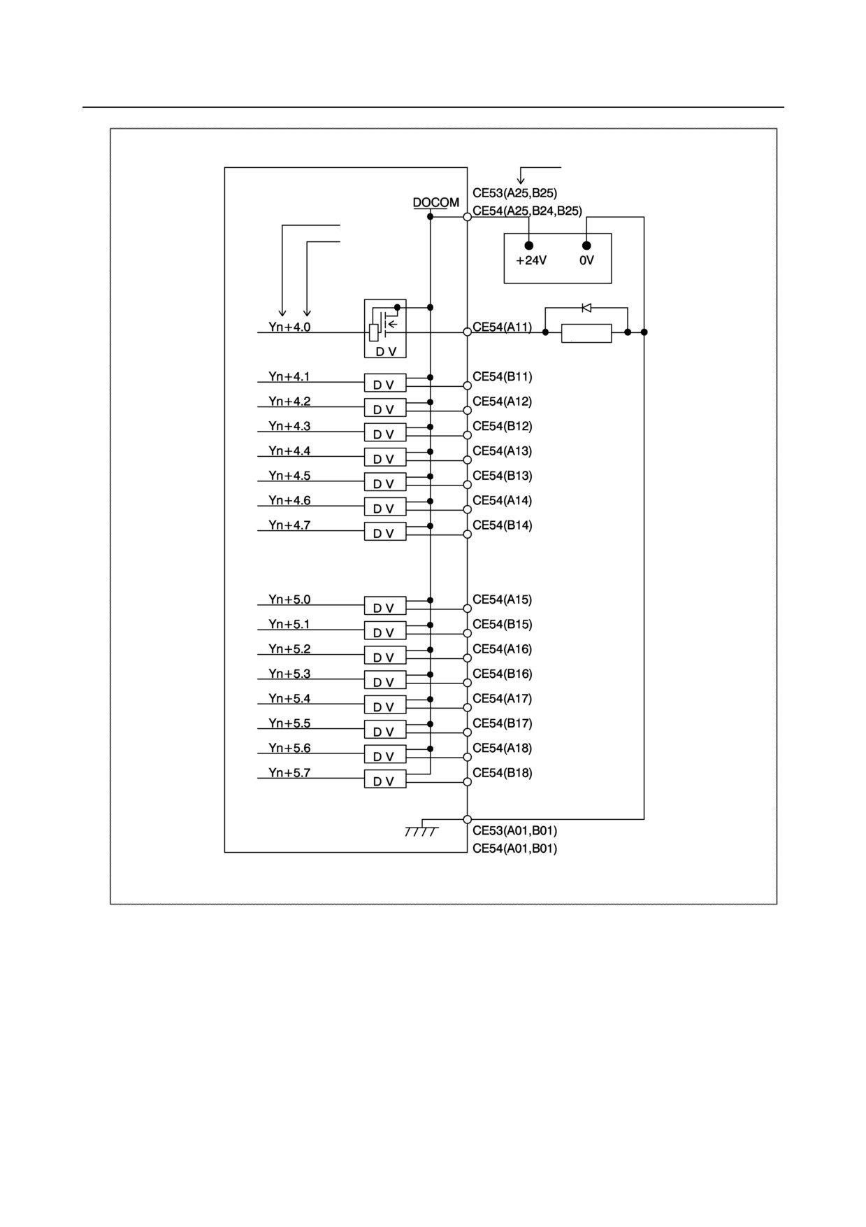
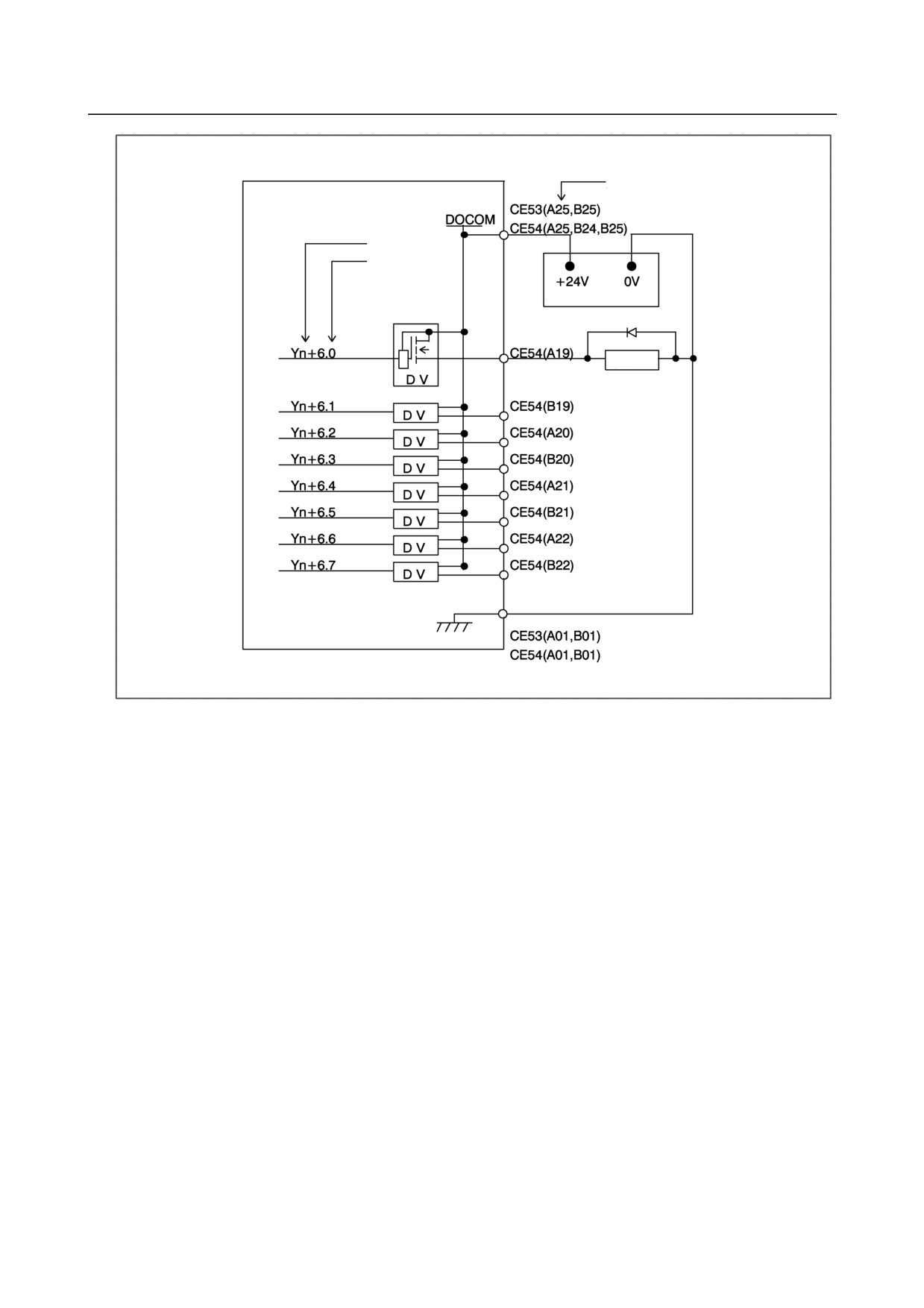
9.3.6
DO (Output Signal) Connection
○ A maximum of 56 points are provided.
Pin No.
Address No.
Bit No.
+24V stabilized power supply
Relay
- 159 -
9.CONNECTION OF I/O Link SLAVE DEVICES
B-64303EN/03
Pin No.
Address No.
Bit No.
+24V stabilized power supply
Relay
- 160 -
B-64303EN/03
9.CONNECTION OF I/O Link SLAVE DEVICES
Pin No.
Address No.
Bit No.
+24V stabilized power supply
Relay
- 161 -
9.CONNECTION OF I/O Link SLAVE DEVICES
B-64303EN/03
Pin No.
Address No.
Bit No.
+24V stabilized power supply
Relay
- 162 -
B-64303EN/03
9.CONNECTION OF I/O Link SLAVE DEVICES
9.3.7
Manual Pulse Generator Connection
For details of the connection of the manual pulse generator, see Subsection 9.2.15.
9.3.8
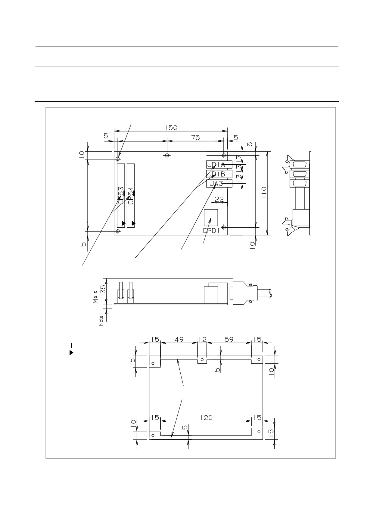
External View
5-φ3.2
65
95
95
24 V power supply connection
Manual pulse generator connection
I/O Link signal connection
Operator's panel DI/DO interface
Note) Lead wires and other components are mounted on the rear face of the printed
circuit board. Ensure that printed circuit boards are spaced 5 mm or more
from one another to prevent interference.
: Polarity guide
: A1 pin mark
Available area to install plate at the rear side
(Perspective drawing viewed from the front)
- 163 -
9.CONNECTION OF I/O Link SLAVE DEVICES
B-64303EN/03
9.3.9
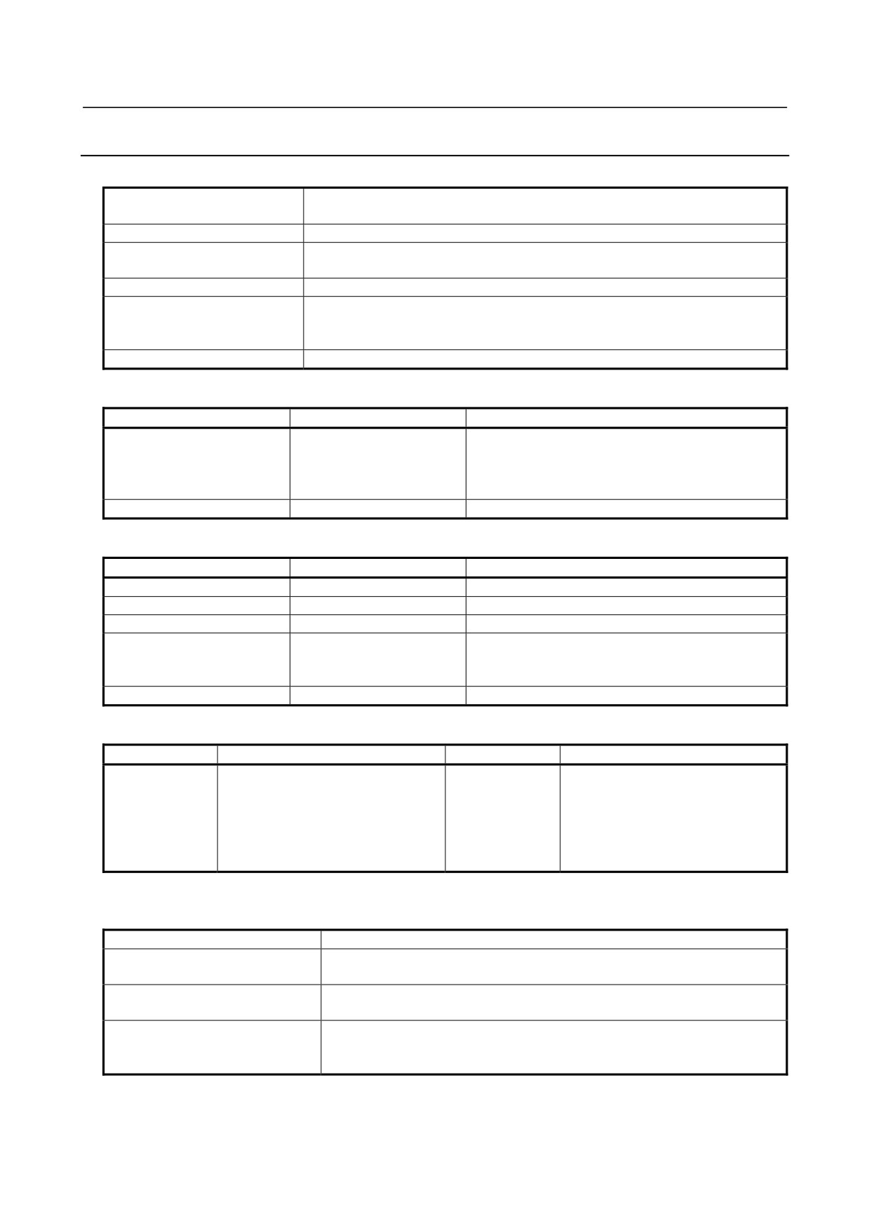
Specifications
Installation specifications
During operation
0°C to 58°C
Ambient temperature
During storage and transportation
-20°C to 60°C
Temperature change
Max.
1.1°C/min.
Normal
75% or less
Relative humidity
Short term (1 month or less)
95% or less
Vibration
During operation
0.5 G or less
Ordinary machining factory environment (Special consideration is required when
Environment
installing the module in a dusty location or where highly concentrated cutting
lubricant or organic solvent is used.)
Other requirements
(1) Install the I/O module in a fully enclosed cabinet.
Ordering specifications
Item
Specification
Remarks
General-purpose DI: 16 points
Matrix DI: 56 points
Operator's panel I/O module
A20B-2002-0470
DO: 56 points
MPG interface is supported.
Fuse (replacement part)
A03B-0815-K001
1A
Module specifications
Item
Specification
Remarks
General-purpose DI
16 points
24-V input
Matrix DI
56 points (8 × 7)
5-V input
DO points
56 points
24 V source type output
Up to 16 modules can be connected as CNC slaves.
CNC interface
FANUC I/O Link connection
Or, amaximum of 1024 points can be supported on
both the input and output sides.
MPG interface
Max. 3 units
Power supply rating
Module
Supply voltage
Current rating
Remarks
The total powerconsumption of DI
24 VDC ±10% supplied from the
points is included.
power supply connector CPD1. The
Operator's panel
(This is true when all generalDI
allowance of ±10% should include
0.35A
I/O module
points are turned on.)
instantaneous voltage and ripple
The power consumption of DO points
voltage.
is not included.
DI (input signal) specifications
(General-purpose input signal)
Contact rating
30 VDC, 16 mA or more
Open circuit intercontact leakage
1 mA or less (at 26.4 V)
current
Closed circuit intercontact
2 V or less (including cable voltage drop)
voltage drop
Receiver delay: Max. 2 ms
Delay
The time required for I/O Link transmission between the CNC and I/O module
(max. 2 ms + CNC ladder scan cycle) must also be taken into account.
- 164 -
B-64303EN/03
9.CONNECTION OF I/O Link SLAVE DEVICES
(Matrix input signal)
Contact rating
6 VDC, 2 mA or more
Open circuit intercontact leakage
0.2 mA or less (at 6 V)
current
Closed circuit intercontact
0.9 V or less (with a current of 1 mA)
voltage drop
The maximum matrix period of 16 ms, the maximum time of I/O Link transfer
Delay
between CNC and I/O module of 2 ms, and the ladder scanning period (by
CNC) must be considered.
NOTE
When detour prevention diodes are used, the voltage drop across closed
contacts indicated above must be maintained, including the diode voltage drop.
DO (output signal) specifications
Maximum load current in ON state
200 mA or less (including momentary current)
Saturation voltage in ON state
Max. 1 V (when load current is 200 mA)
Withstand voltage
24 V ±20% or less (including momentary values)
Leakage current in OFF state
20 μA or less
Driver delay: Max. 50 μs
The time required for I/O Link transmission between the CNC and I/O
Delay
module (max. 2 ms + CNC ladder scan cycle) must also be taken into
account.
NOTE
Ensure that the maximum current per DOCOM pin (DO power supply pin) does
not exceed 0.7 A.
9.3.10 Other Notes
DO signal reaction to a system alarm
There is a possibility that the I/O module will not operate normally due to a failure of CNC or I/O Link
slave module, or abnormally power supply voltage. To prevent accidents even in this case, design the
machine to operate safely by making a safety circuit outside the I/O module.
The circuit of this I/O module is designed so that all DO signals are turned off if a system alarm is
occurred in the CNC which controls the I/O module, or if a power of the CNC or the I/O module is turned
off. However, it cannot be guaranteed that DO signals of the I/O module will certainly be turned off.
Therefore, manage signals related to safety by making a safety circuit outside this I/O module.
- 165 -
9.CONNECTION OF I/O Link SLAVE DEVICES
B-64303EN/03
Address allocation
For the operator's panel I/O module, I/O addresses are mapped as follows.
DI space map
DO space map
Xm
General-purpose
Yn
input signal
Xm+1
Yn+1
Xm+2
Yn+2
Reserved
Output signal
Xm+3
Yn+3
Xm+4
Yn+4
Xm+5
Yn+5
Xm+6
Yn+6
Matrix input
Xm+7
signal
Yn+7
Reserved
Xm+8
Xm+9
Xm+10
Xm+11
Reserved
Xm+12 (for 1st MPG)
Xm+13 (for 2nd MPG)
MPG
Xm+14 (for 3rd MPG)
Xm+15 (DO alarm
DO alarm
detection)
detection
The operator's panel I/O module is allocated a group of DI addresses (16 bytes) and a group of DO
addresses (8 bytes). This address allocation is explained below.
The MPG interface (MPG counter) occupies DI space from Xm+12 through Xm+14. These addresses
are fixed, and Xm+12 through Xm+14 must be allocated as a DI work area to enable the use of the MPG.
Therefore, when using an MPG for the i series CNC, allocate DI addresses in units of 16 bytes. Do not
use the DI space from Xm+12 through Xm+14 for Ladder; the CNC processes the MPG counter value
directly.
DI address Xm+15 is used for detecting overcurrent and overheating alarms that may occur in the IC used
in the DO driver.
[For details, see the section describing the detection of DO (output signal) alarms.]
This address is fixed, and must be allocated as a work area before it can be used. Therefore, when using
this area, allocate DI addresses in units of 16 bytes.
Basically, I/O addresses can be allocated to the operator's panel I/O module freely. When allocating DI
addresses, however, consider also the fixed addresses that are directly supervised by the CNC, and keep
the following in mind.
Fixed addresses directly supervised by the CNC (Example: Series 0i)
7
6
5
4
3
2
1
0
X0004
SKIP
ESKIP
-MIT2
+MIT2
-MIT1
+MIT1
XAE2
XAE1
SKIP6
SKIP5
SKIP4
SKIP3
SKIP2
SKIP8
SKIP7
SKIP
ESKIP
SKIP5
SKIP4
SKIP3
XAE3
XAE2
XAE1
SKIP6
SKIP2
SKIP8
SKIP7
X0005
X0006
X0007
X0008
*ESP
X0009
*DEC5
*DEC4
*DEC3
*DEC2
*DEC1
The upper row indicates the T series (first path), and the lower row indicates the M series.
- 166 -