FANUC Series 0i-MODEL D, Series 0i Mate-MODEL D. CONNECTION MANUAL (HARDWARE) - page 3
B-64303EN/03
5.CONNECTION TO CNC PERIPHERALS
-
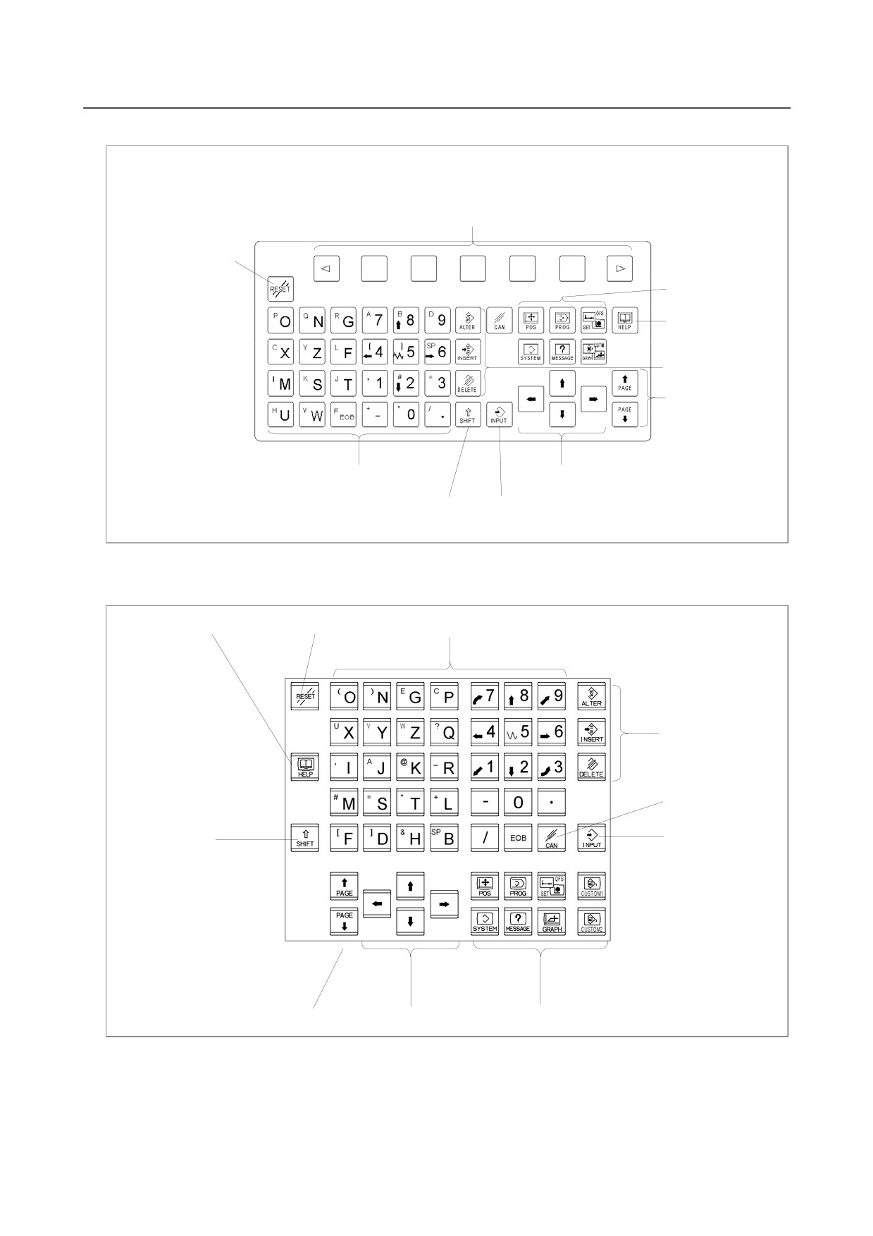
Small MDI unit (OGN keys, vertical type)
Soft keys
RESET key
Function keys
HELP key
Edit keys
Page change keys
Address keys/Numeric keys
Cursor move keys
SHIFT key
INPUT key
For Machining center (M series)
-
Standard MDI unit (ONG keys)
HELP key
RESET key
Address keys/Numeric keys
Edit keys
Cancel (CAN) key
SHIFT key
INPUT key
Page change keys
Cursor move keys
Function keys
- 47 -
5.CONNECTION TO CNC PERIPHERALS
B-64303EN/03
-
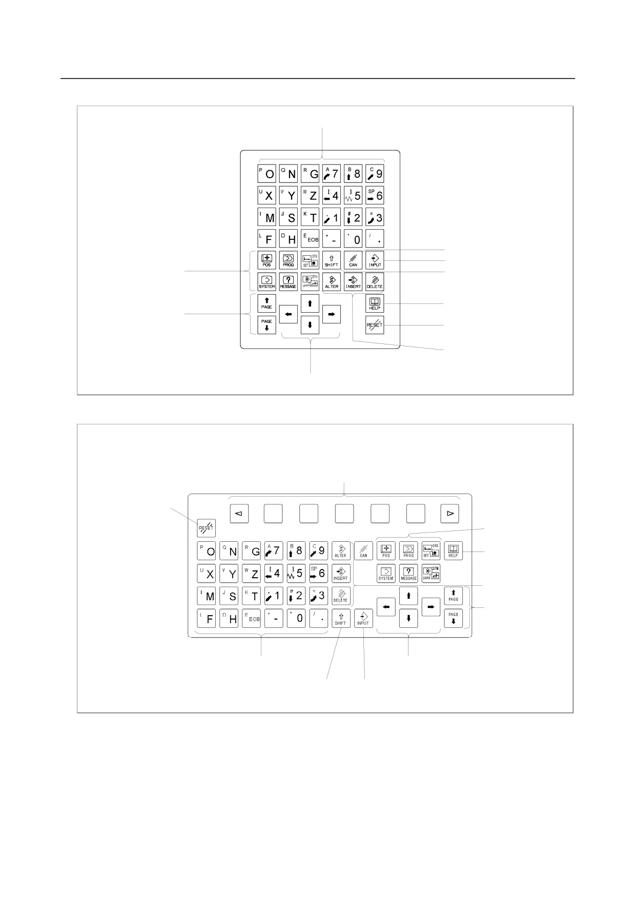
Small MDI unit (OGN keys, horizontal type)
Address keys/Numeric keys
Cancel (CAN) key
INPUT key
Function keys
SHIFT key
HELP key
Page change keys
RESET key
Edit keys
Cursor move keys
-
Small MDI unit (OGN keys, vertical type)
Soft keys
RESET key
Function keys
HELP key
Edit keys
Page change keys
Address keys/Numeric keys
Cursor move keys
SHIFT key
INPUT key
- 48 -
B-64303EN/03
5.CONNECTION TO CNC PERIPHERALS
5.2
CONNECTION WITH INPUT/OUTPUT DEVICES
5.2.1
Overview
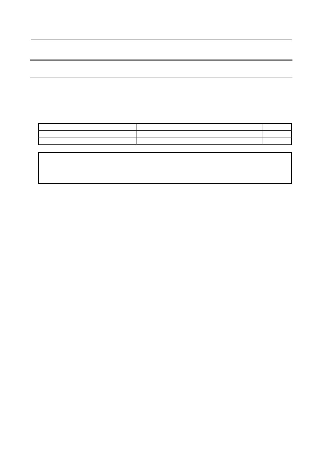
An input/output device is used to enter information such as CNC programs and parameters from an
external device to the CNC, or to output information from the CNC to an external device.
The interface of the input/output devices electrically conforms to RS-232-C, so that a connection can be
made with a device that has an RS-232-C interface.
The tables below indicate the serial ports of this CNC.
Port name
Interface location
First channel (JD36A)
Main control unit
Second channel (JD36B)
Main control unit
Note
NOTE
When using the touch panel, the interface of the second channel cannot be used
as the interface of input/output devices because it is used to communicate with
the touch panel on the CNC side.
- 49 -
5.CONNECTION TO CNC PERIPHERALS
B-64303EN/03
5.2.2
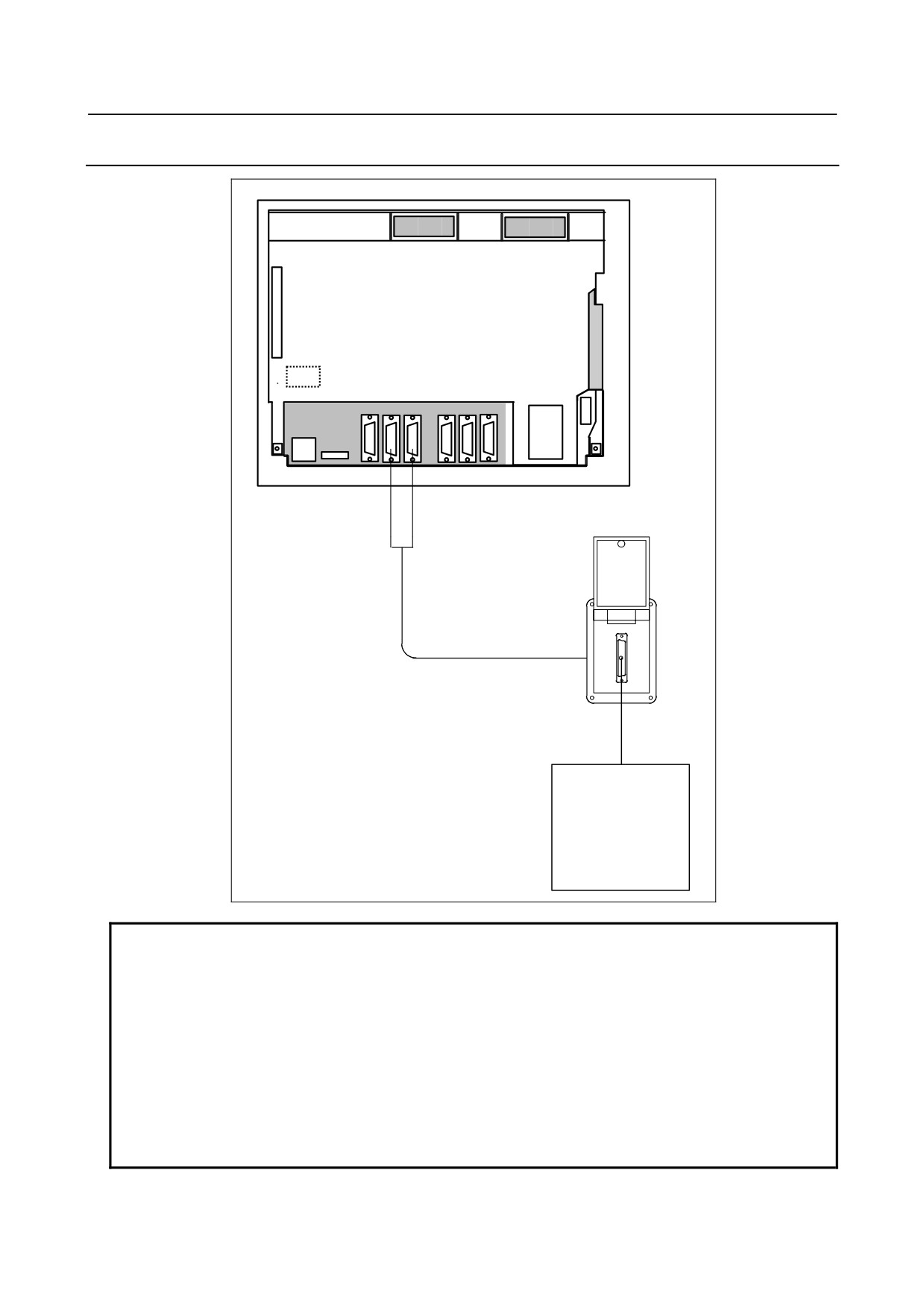
Connecting I/O Devices
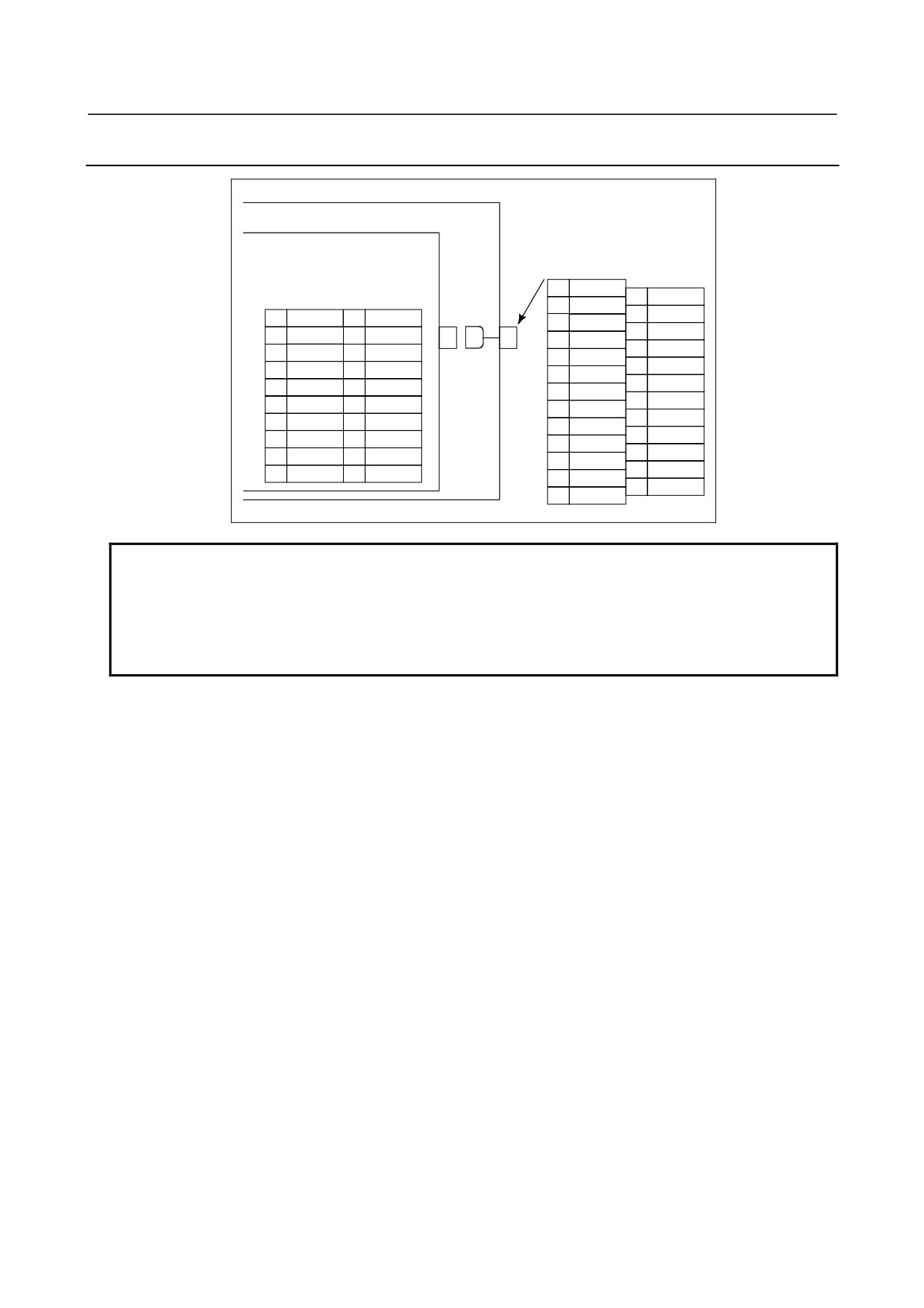
Unit rear panel
Punch panel
R232-1
R232-2
JD36A
JD36B
I/O device
NOTE
When the PANEL i is used in the stand-alone type, the RS-232-C interface on
the PC side is normally used to input or output parameters or programs. The
cases where the PANEL i is used and RS-232-C interface on the CNC side is
used are described below.
• Ladder uploading or downloading via RS-232-C using FANUC LADDER or
FANUC LADDER II
• Ladder monitoring from an external PC using FANUC LADDER III
• DNC operation via RS-232-C, external I/O device control
• Input/output of parameters and programs by using the CNC screen display
function
- 50 -
B-64303EN/03
5.CONNECTION TO CNC PERIPHERALS
5.2.3
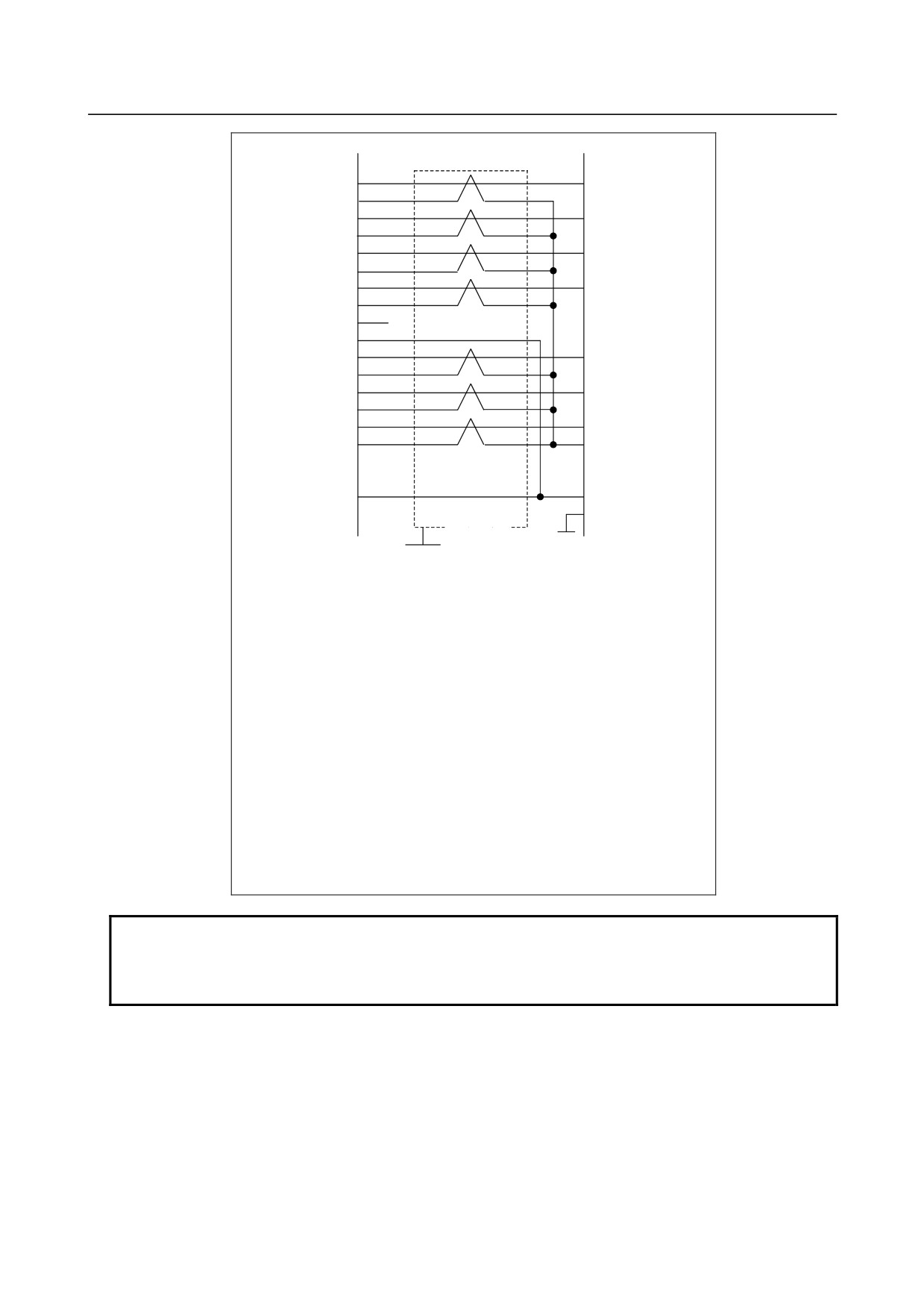
RS-232-C Serial Port
CNC
Relay connector
JD36A, JD36B
(DBM-25S)
FI80-20P, DF1R020WB1
(PCR-EV20MDT)
1
FG
14
2
SD
15
1
RD
11
SD
3
RD
16
2
0V
12
0V
>
>
<
4
RS
17
3
DR
13
ER
5
CS
18
4
0V
14
0V
6
DR
19
5
CS
15
RS
7
SG
20
ER
6
0V
16
0V
8
CD
21
7
CD
17
(*)
9
8
0V
18
(+5V)(*)
22
10
23
9
(*)
19
+24V
11
24
10
+24V
20
(+5V)(*)
12
25
+24V
13
NOTE
1
+24 V can be used as the power supply for FANUC RS-232-C equipment.
2 Do not connect anything to those pins for which signal names are not indicated.
3 Pins 18 and 20 (+5V) are provided for touch channel connection.
4 The upper connector names on the CNC side are for the LCD-mounted type.
The lower connector name in parentheses is for the stand-alone type.
- 51 -
5.CONNECTION TO CNC PERIPHERALS
B-64303EN/03
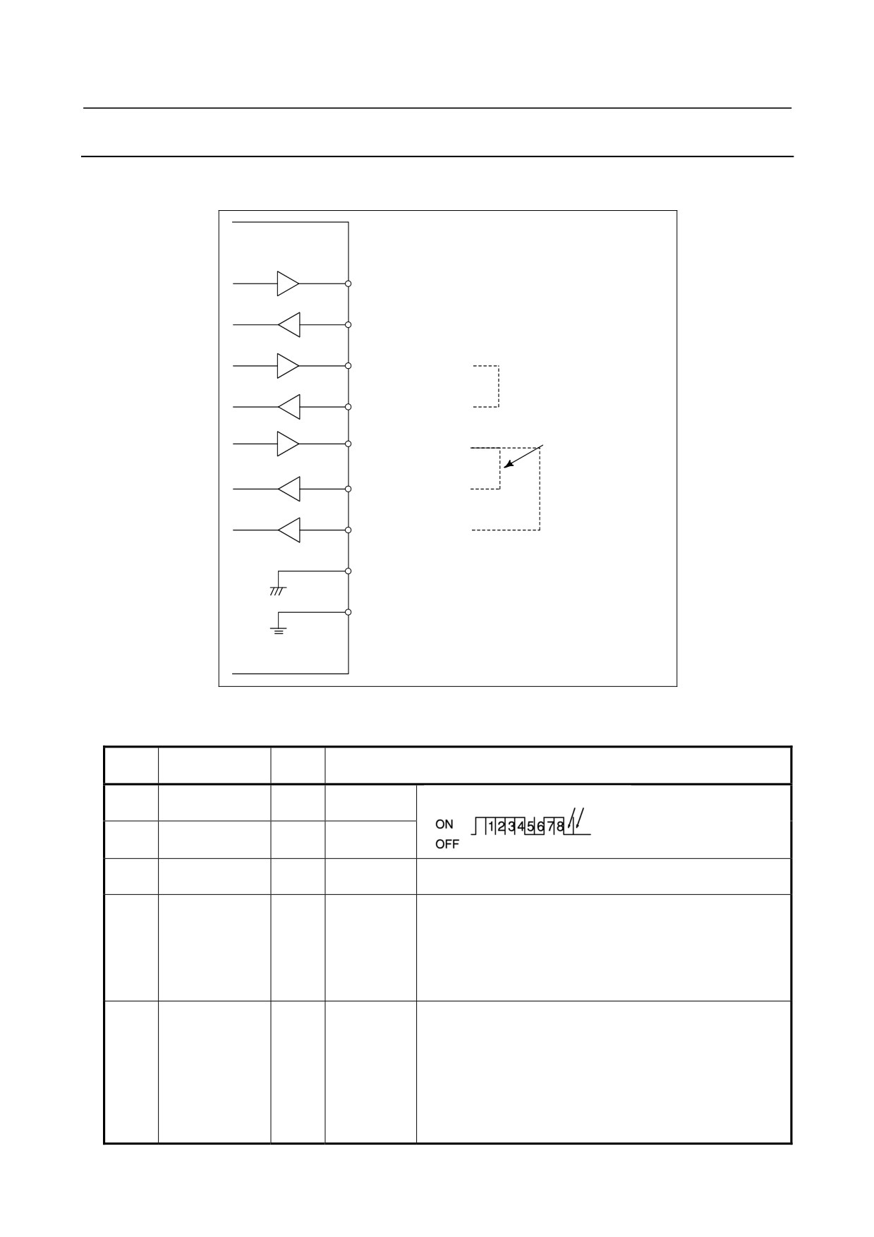
Cable connection
1
3
RD
RD
2
0V
3
6
DR
DR
4
0V
5
5
CS
CS
6
0V
7
8
CD
CD
8
0V
9
10
+24V
11
2
SD
SD
12
0V
13
20
ER
ER
14
0V
15
4
RS
RS
16
7
0V
17
18
19
25
+24V
+24V
20
1
FG
Shield
GND
Grounding plate
Recommended wire specification
A66L-0001-0284#10P (#28AWG × 10 pairs)
Recommended cable-side connectors(JD36A, JD36B)
PCR-E20FA (Honda Tsushin Kogyo Co., Ltd.)
FI30-20S (Hirose Electric Co., Ltd.)
FCN-247J020-G/E (Fujitsu, Ltd.)
52622-2011 (Molex Japan Co., Ltd.)
Recommended cable specification (Name : PUNCH PANEL)
For LCD-mounted type
<Narrow width type>
A02B-0236-C191 (1m)
A02B-0236-C192 (2m)
A02B-0236-C193 (5m)
Recommended cable specification (Name : PUNCH PANEL)
For stand alone type
<Narrow width type>
A02B-0120-C191 (1m)
A02B-0120-C192 (2m)
A02B-0120-C193 (5m)
NOTE
1 Do not connect anything to those pins for which signal names are not indicated.
2 Recommended cable connector FI30-20S (Hirose Electric) cannot be used for
the stand-alone type.
- 52 -
B-64303EN/03
5.CONNECTION TO CNC PERIPHERALS
5.2.4
RS-232-C Interface Specification
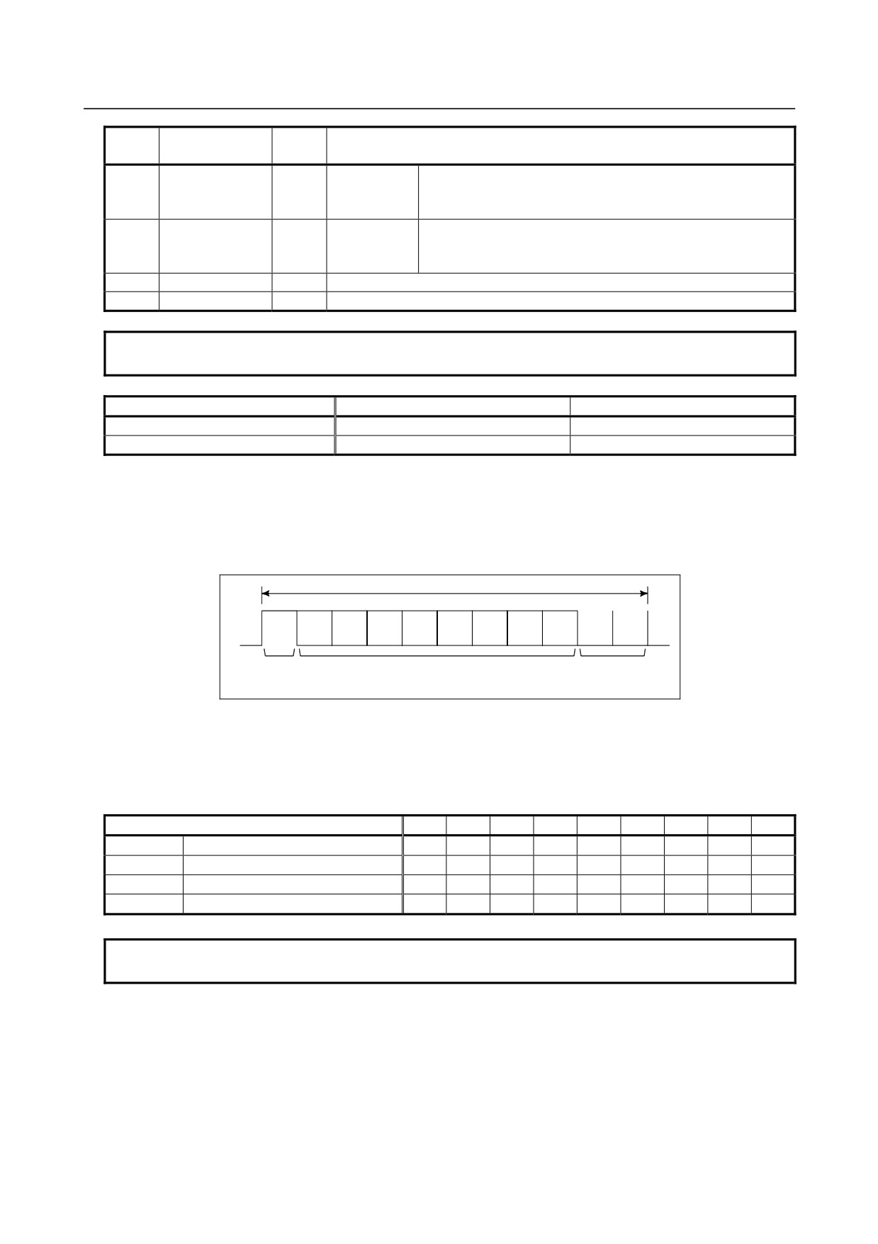
RS-232-C Interface signals
Generally signals as follows are used in RS-232-C interface.
CNC
Output
SD (Send data)
Input
RD (Receive data)
RS (Request to Send)
When CS is not used short CS
and RS.
CS (Enable to send)
When DR is not used
short DR and ER.
ER (Ready)
DR (Data set ready)
Always short ER and
CD (Check data)
CD.
SG (Signal ground)
FG (Frame ground)
Fig. 5.3.4 (a) RS-232-C interface
Signal description of RS-232-C interface
Signal
RS-232C circuit
I/O
Description
name
number
SD
103
Output
Sending
Start bit
Stop bits
data
RD
104
Input
Receiving
(When ISO code 0 is sent)
data
RS
105
Output
Sending
This signal is set to on when NC starts sending data and is
request
turned off when transmission ends.
CS
106
Input
Sending
When both this signal and the DR signal are set, the NC can
permitted
send data. If external device processing is delayed by a
punching operation, etc., NC data sending can be stopped by
turning off this signal after sending two characters, including
the data being sent currently. If this signal will not be used,
make sure to strap this signal circuit to the RS signal circuit.
DR
107
Input
Data set
When external device is ready to operate, this signal is set.
ready
This signal should usually be connected to the signal
indicating external device power supply being on. (ER signal
of external device). See Note below.
The NC transfers data when this signal is set. If the signals
turned off during data transfer, alarm 086 is issued. If the DR
signal will not be used, make sure to strap this signal circuit
to the ER signal circuit.
- 53 -
5.CONNECTION TO CNC PERIPHERALS
B-64303EN/03
Signal
RS-232C circuit
I/O
Description
name
number
ER
108.2
Output
NC ready to
This signal is set when the NC is ready to operate. External
operation
device should regard the SD signal as being significant when
the ER signal is set.
CD
109
Input
Signal
Since this signal is not used in connections with external
Condition
device, the signal circuit must be strapped, inside the
connecting cable, to the ER signal circuit.
SG
102
Signal grounding
FG
101
Frame grounding
NOTE
Signal on/off state is defined as follows;
-3V or lower
+3V or higher
Function
OFF
ON
Signal Condition
Marking
Spacing
Transmission Method of RS-232-C interface
-
Start-stop
Generally, two transmission methods are available at the serial interface. This CNC use the start-stop
method.
With this method, start and stop signals are output before and after each data bit.
One character in start-stop
b1
b2
b3
b4
b5
b6
b7
b8
Start bit
Data bit
Stop bits
(8 bit including one parity bit)
(2 bits)
-
Codes
Transmission codes are as follows:
(i)
EIA code and Control codes DC1 to DC4.
(ii) ISO code and Control codes DC1 to DC4 (Optional ISO code input is necessary.)
The connected external device must be able to recognize the following control codes, sent from NC.
Control code
8
7
6
5
4
3
2
1
DC1
Tape reader start
○
○
○
DC2
Tape punch designation
○
○
○
DC3
Tape reader stop
○
○
○
○
○
DC4
Tape punch release
○
○
○
NOTE
The listed control codes are used for both EIA and ISO.
In this interface, control codes DC1 to DC4 are used.
(a) NC can control external device by issuing codes DC1 to DC4.
(b) When external processing falls behind the pace of the NC signals (When NC issues data)
(i)
External device can temporarily stop NC data output by using the NC's CS signal. Data output
stops within two characters including a currently transmitting character when CS OFF signal is
input to NC. When CS signal is turned on again, data transmission start.
(ii) If control code DC3 is input to NC, NC stops data output within ten characters. When control
code DC1 is input to NC, NC starts sending data again.
- 54 -
B-64303EN/03
5.CONNECTION TO CNC PERIPHERALS
(c) When the external device is equipped with an ISO/EIA converter, the external device must satisfy
the specification shown in Table 5.3.4.
Table 5.3.4
ISO code
EIA code
Meaning
Character
8
7
6
5
4
3
2
1
Character
8
7
6
5
4
3
2
1
0
○
○
●
0
○
●
Numeral
0
1
○
○
○
●
○
1
●
○
Numeral
1
2
○
○
○
●
○
2
●
○
Numeral
2
3
○
○
●
○
○
3
○
●
○
○
Numeral
3
4
○
○
○
●
○
4
●
○
Numeral
4
5
○
○
●
○
○
5
○
●
○
○
Numeral
5
6
○
○
●
○
○
6
○
●
○
○
Numeral
6
7
○
○
○
●
○
○
○
7
●
○
○
○
Numeral
7
8
○
○
○
○
●
8
○
●
Numeral
8
9
○
○
○
●
○
9
○
○
●
○
Numeral
9
A
○
●
○
a
○
○
●
○
Address
A
B
○
●
○
b
○
○
●
○
?
Address
B
C
○
○
●
○
○
c
○
○
○
●
○
○
Address
C
D
○
●
○
d
○
○
●
○
?
Address
D
E
○
○
●
○
○
e
○
○
○
●
○
○
?
Address
E
F
○
○
●
○
○
f
○
○
○
●
○
○
Address
F
G
○
●
○
○
○
g
○
○
○
●
○
○
○
Address
G
H
○
○
●
h
○
○
○
●
Address
H
I
○
○
○
●
○
i
○
○
○
○
●
○
Address
I
J
○
○
○
●
○
j
○
○
●
○
○
?
Address
J
K
○
○
●
○
○
k
○
○
●
○
Address
K
L
○
○
○
●
○
l
○
●
○
○
?
Address
L
M
○
○
●
○
○
m
○
○
●
○
Address
M
N
○
○
●
○
○
n
○
●
○
○
Address
N
O
○
○
○
●
○
○
○
o
○
●
○
○
Address
O
P
○
○
●
p
○
○
●
○
○
○
Address
P
Q
○
○
○
●
○
q
○
○
○
●
Address
Q
R
○
○
○
●
○
r
○
○
●
○
Address
R
S
○
○
●
○
○
s
○
○
●
○
Address
S
T
○
○
○
●
○
t
○
●
○
○
Address
T
U
○
○
●
○
○
u
○
○
●
○
Address
U
V
○
○
●
○
○
v
○
●
○
○
?
Address
V
W
○
○
○
●
○
○
○
w
○
●
○
○
Address
W
X
○
○
○
○
●
x
○
○
●
○
○
○
Address
X
Y
○
○
○
●
○
y
○
○
○
●
?
Address
Y
Z
○
○
○
●
○
z
○
○
●
○
Address
Z
DEL
○
○
○
○
○
●
○
○
○
Del
○
○
○
○
●
○
○
○
*
NUL
●
Blank
●
*
BS
○
○
●
BS
○
○
●
○
*
HT
○
●
○
Tab
○
○
○
●
○
○
*
LF or NL
○
●
○
CR or
○
●
EOB
CR
○
○
●
○
○
*
SP
○
○
●
SP
○
●
*
%
○
○
●
○
○
ER
○
●
○
○
(
○
○
●
( 2-4-5 )
○
○
●
○
)
○
○
○
●
○
( 2-4-7 )
○
○
●
○
+
○
○
●
○
○
+
○
○
○
●
*
-
○
○
●
○
○
-
○
●
:
○
○
○
●
○
/
○
○
○
●
○
○
○
/
○
○
●
○
○
○
●
○
○
○
○
○
●
○
○
#
○
○
●
○
○
$
○
●
○
&
○
○
●
○
○
&
○
●
○
○
*
○
●
○
○
○
*
*
○
○
○
●
○
*
,
○
○
○
●
○
,
○
○
○
●
○
○
*
;
○
○
○
○
●
○
○
*
<
○
○
○
●
○
*
=
○
○
○
○
●
○
○
*
>
○
○
○
○
●
○
○
*
?
○
○
○
●
○
○
○
*
@
○
○
●
*
”
○
○
*
- 55 -
5.CONNECTION TO CNC PERIPHERALS
B-64303EN/03
NOTE
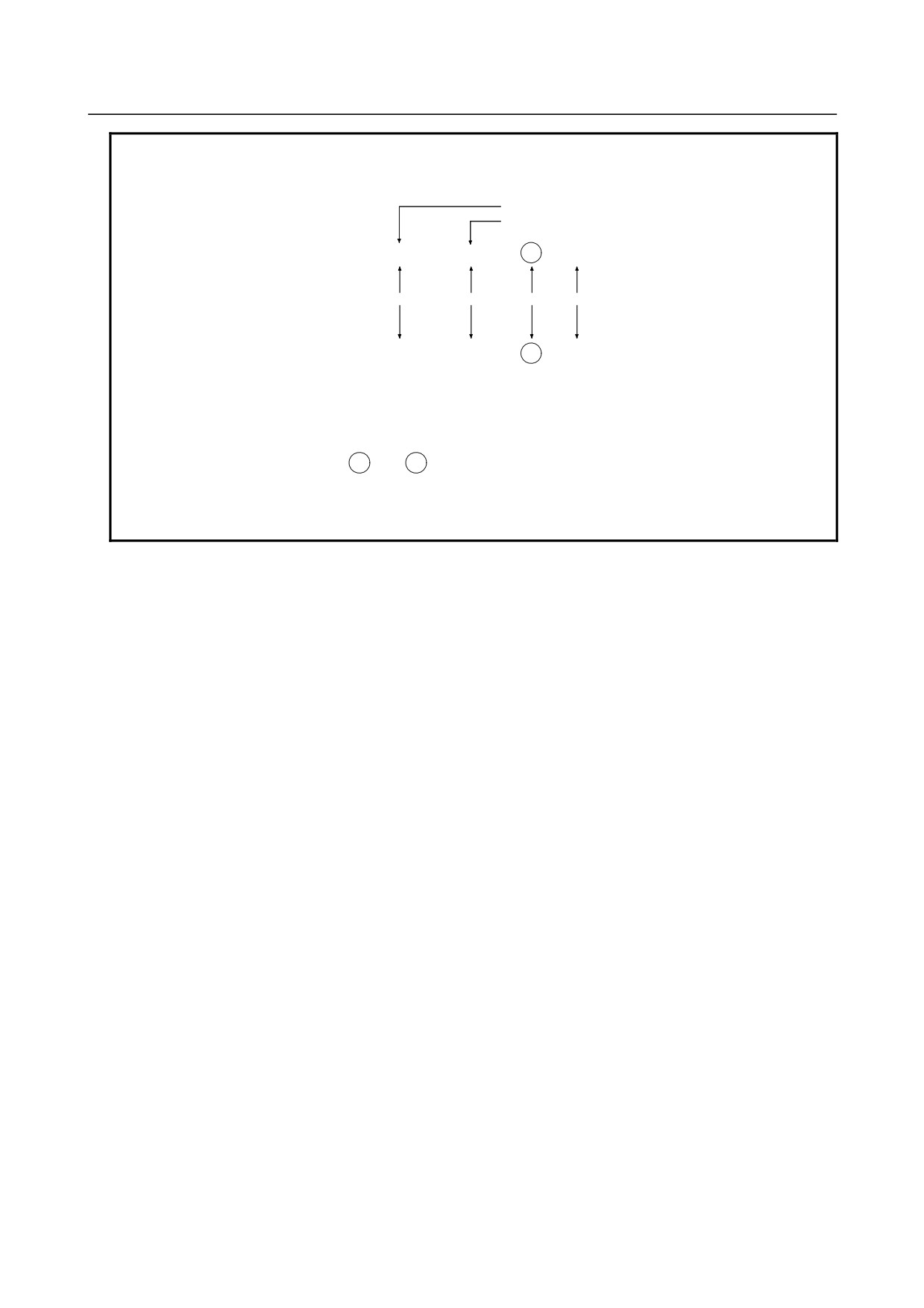
1 When the external device is equipped with an ISO/EIA converter, the following
items must be noted in Table 5.3.4 (a).
Control out (Comment field start)
Control in (Comment field end)
EIA code
(
))
CR
o
Condition 1
Condition 1 Condition 2 Condition 3
ISO code
(
)
LF
:
Condition1 Left parenthesis "("of the ISO code punches holes at bits 2, 4 and 5
when used in the EIA code.
Right parenthesis ")"of the ISO code punches holes at bits 2, 4 and
7 when used in the EIA code.
Condition2 EIA code CR is LF in ISO code.
Condition3 EIA code O is : in ISO code.
2 Control codes DC1 to DC4 are transmission codes output from the NC.
So they need not to be punched on the NC tape.
(3) Transmission rate (Baud rate)
The transmission rate (Baud rate) is the number of bits transferred per second.
The following baud rates are available depending on the system parameter.
50, 100, 110, 150, 200, 300, 600, 1200, 2400, 4800, 9600, 19200
[Example]
Baud rate : 110
When using one start bit and two stop bits (totalling 11 bits per character):
Transmission characters/second= 110/11
=10 characters/second (Max.)
(4) Cable length
The cable length depends on the external device type. Consult with the device manufacturers for
actual connecting cable lengths.
Cable length is as follows by the specification of NC.
for RS-232C
100m or less
4800 bauds or less
50m or less
19200 bauds or less
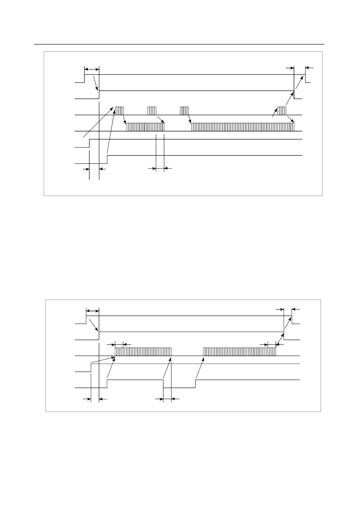
Time chart when the NC receives data (Read into memory)
(1) NC outputs DC1.
(2) The I/O device starts sending data upon receiving DC1.
(3) NC sends DC3 when NC processing is delayed.
(4) The I/O device stops sending data to NC after receiving DC3.
The device may send up to 10 characters after receiving DC3. If it sends more than 10 characters,
alarm 087 will occur.
(5) NC reissues DC1 upon completing delayed processing.
(6) The I/O device restarts data output upon receiving the DC1 code (the data must be the next data to
the preceding.)
(7) NC sends DC3 upon completing data read.
(8) The I/O device stops sending data.
- 56 -
B-64303EN/03
5.CONNECTION TO CNC PERIPHERALS
10ms or longer
100ms or longer
ER
(output)
RS (output)
DC1
DC3
DC1
DC3
SD (output)
ER code
RD (input)
DR (input)
CS (input)
Up to 10 characters
1ms or longer
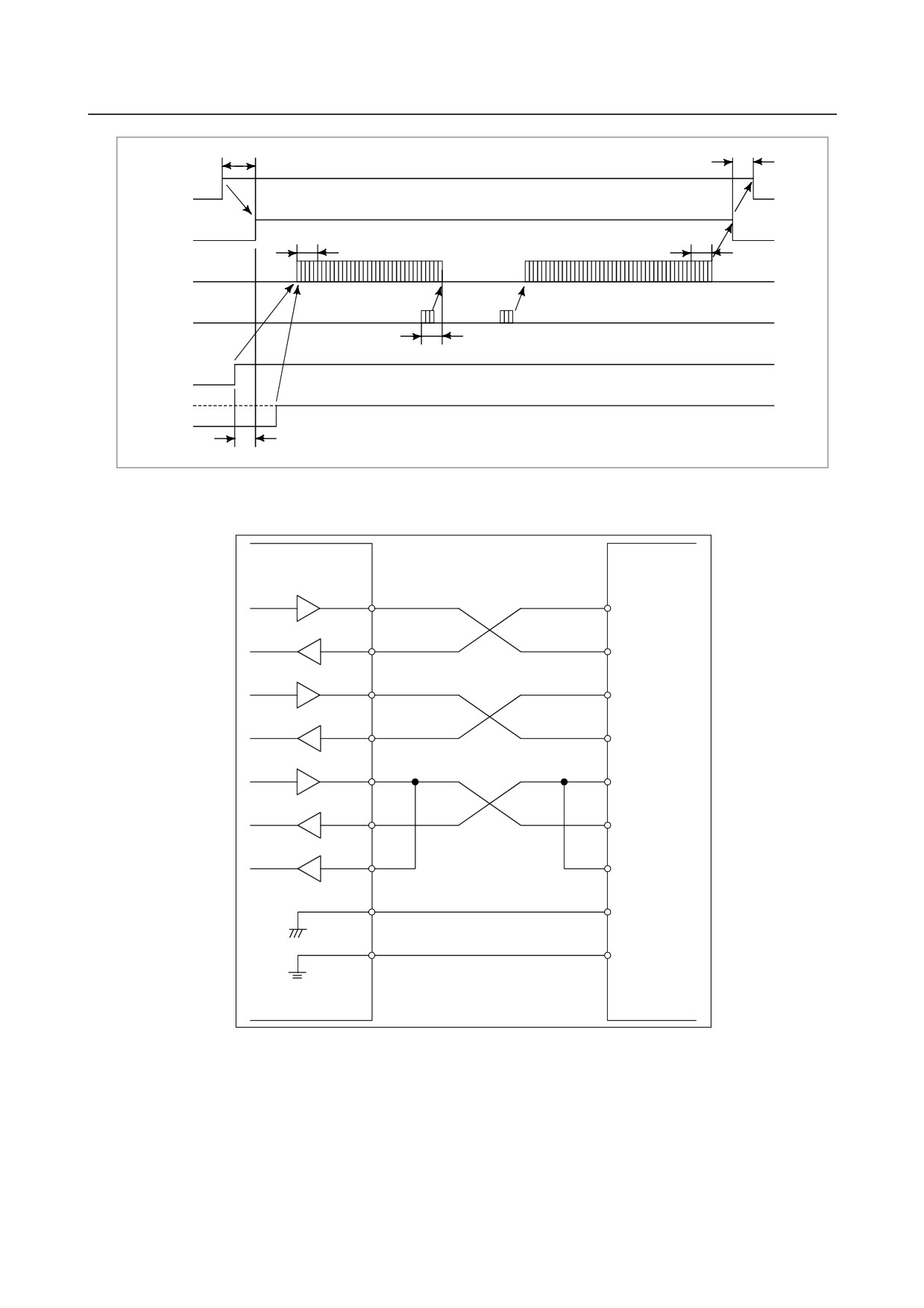
Time chart when the NC send data (Punch out)
(1) NC output DC2.
(2) NC outputs punch data in succession.
(3) When data processing is delayed at the I/O device.
(a) Data output stops within two characters including a currently transmitting character when CS
signal is turned off.
When CS signal is turned on again, data transmission starts. (See Fig. 5.3.4 (b))
(b) If control code DC3 is input to NC, NC stops data output within ten characters. When control
code DC1 is input to NC, NC starts sending data again. (See Fig. 5.3.4 (c))
(4) The NC starts sending the next data if the CS signal is turned on after the I/O device completes data
processing.
(5) The NC issues DC4 upon completing data output.
10ms or longer
100ms or longer
ER (output)
RS (output)
DC2
DC4
SD (output)
RD (input)
CS (input)
1ms or longer
Within 2 characters
Fig. 5.3.4 (c)
- 57 -
5.CONNECTION TO CNC PERIPHERALS
B-64303EN/03
10ms or longer
100ms or longer
ER (output)
RS (output)
DC2
DC4
SD (output)
DC3
DC1
RD (input)
Within 2 characters
DR (input)
CS (input)
1ms or longer
Fig. 5.3.4 (c)
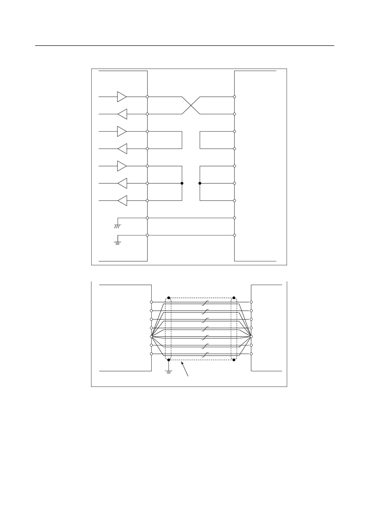
Connection between RS-232-C interface and external device
CNC side
I/O device
side
SD
SD
RD
RD
RS
RS
CS
CS
ER
ER
DR
DR
CD
CD
SG
SG
FG
FG
- 58 -
B-64303EN/03
5.CONNECTION TO CNC PERIPHERALS
● Use the connection shown in the figure below when the ER and DR signals are not used for
handshaking.
CNC side
I/O device side
SD
SD
RD
RD
RS
RS
CS
CS
ER
ER
DR
DR
CD
CD
SG
SG
FG
FG
he cable for connecting the I/O device to the CNC should be connected as shown in the below diagram.
Serial interface
SD
RD
RS
CS
SG
ER
DR
Cable : twist 10 pairs × 0.18mm2, with shield
- 59 -
5.CONNECTION TO CNC PERIPHERALS
B-64303EN/03
5.3
CONNECTING THE HIGH-SPEED SKIP (HDI)
5.3.1
Connecting the High-speed Skip (HDI)
CNC
JA40
FI80-20P, DF1R020WB1
(PCR-EV20MDT)
1
HDI0
11
HDI1
2
0V
12
0V
3
HDI2
13
HDI3
4
0V
14
0V
5
0V
15
6
16
7
17
8
18
9
19
10
0V
20
NOTE
1 The upper connector specification on the JA40 is for the LCD-mounted type.
The lower connector specification in parentheses is for the stand-alone type.
2 Do not connect any signal to the pins with no signal name.
- 60 -
B-64303EN/03
5.CONNECTION TO CNC PERIPHERALS
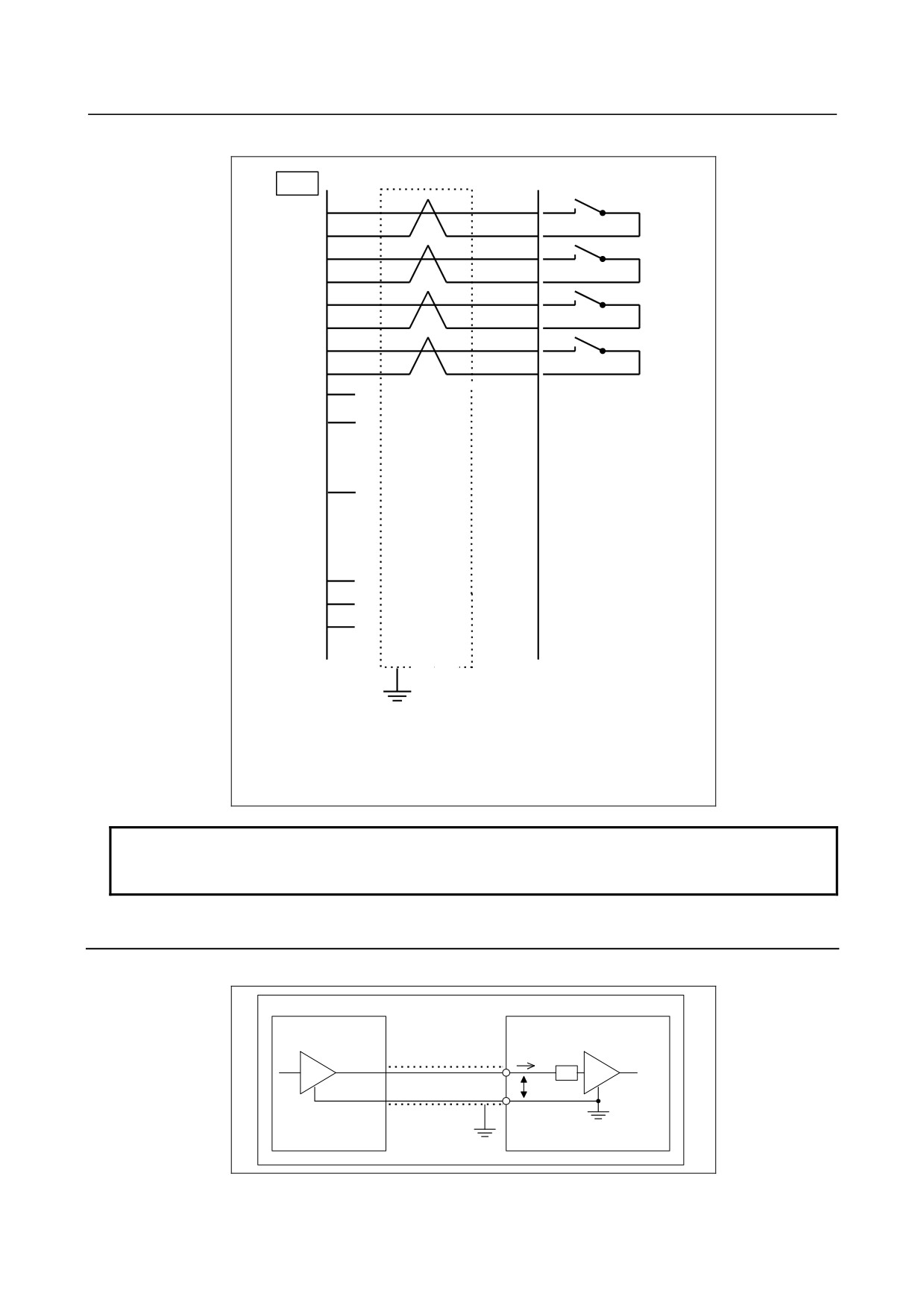
Cable connections
JA40
1
HDI0
2
0V
11
HDI1
12
0V
3
HDI2
4
0V
13
HDI3
14
0V
6
5
0V
15
16
17
18
19
20
7
8
9
10
0V
Shield
Ground plate
Recommended cable connector:
PCR-E20FA (Honda Tsushin Kogyo)
FI30-20S (Hirose Electric)
FCN-247J020-G/E (Fujitsu)
52622-2011 (Molex Japan)
NOTE
Recommended cable connector FI30-20S (Hirose Electric) cannot be used for
the stand-alone type.
5.3.2
Input Signal Rules for the High-speed Skip (HDI)
Circuit configuration
CNC
DRIVER
IiL/IiHFILTER
RECEIVER
VH/VL
SHIELD
- 61 -
5.CONNECTION TO CNC PERIPHERALS
B-64303EN/03
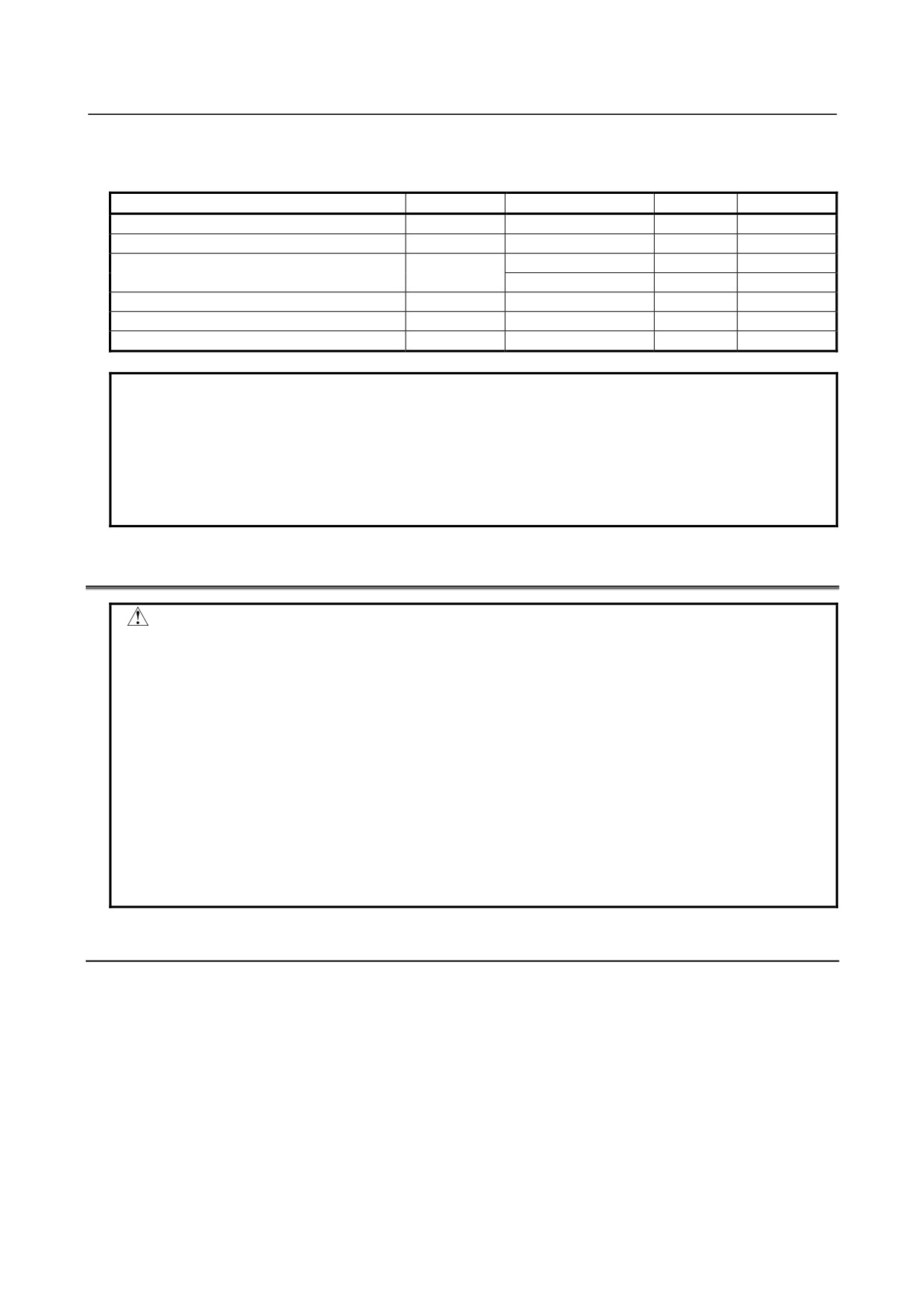
Absolute maximum rating
Input voltage range Vin: -3.6 to +13.6 V
Input characteristics
Unit
Symbol
Specification
Unit
Remark
High level input voltage
VH
3.6 to 11.6
V
Low level input voltage
VL
0 to 1.0
V
2 (max)
mA
Vin=5V
High level input current
IiH
11 (max)
mA
Vin=10V
Low level input current
IiL
-8.0 (max)
mA
Vin=0V
Input signal pulse duration
20 (min)
μs
Input signal delay or variations
0.02 (max)
ms
NOTE
1 The plus (+) sign of IiH/IiL represents the direction of flow into the receiver. The
minus (-) sign of IiH/IiL represents the direction of flow out of the receiver.
2 The high-speed skip signal is assumed to be 1 when the input voltage is at the
low level and 0 when it is at the high level.
3 The input level for the CNC receiver is high when the circuit is open. So, the
input level for the external driver must be low.
5.4
LINKING THE EMBEDDED ETHERNET INTERFACE
CAUTION
Before attaching or removing cables, power off the CNC main unit, and confirm
that the power is off.
Ask the respective manufacturers for explanations about how to build a network
and about conditions for using units (such as a media converter, hub,
transceiver, and cable) other than the CNC unit. When installing network
cables, exercise sufficient caution so that the network will not be affected by any
noise source. Electrically separate the network wiring sufficiently from noise
sources like motors and their power lines. Also, ground each unit as required.
If the grounding impedance is high, it may cause trouble in communication.
Once the equipment is installed, conduct communication tests to verify normal
operation before starting actual use of the equipment.
FANUC is not liable to any damage related to trouble arising from any unit other
than the CNC unit.
5.4.1
Connection to the Ethernet Interface
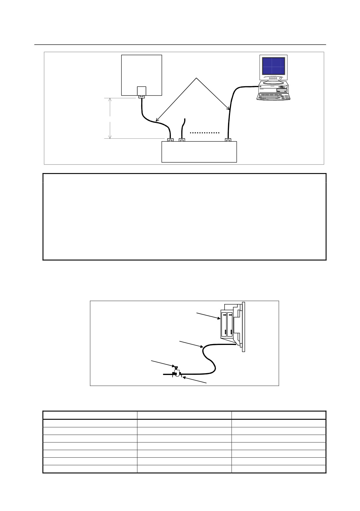
The 100BASE-TX interface are available. A hub (line concentrator) is used to connect the CNC unit to
a system. A typical connection example is shown below.
- 62 -
B-64303EN/03
5.CONNECTION TO CNC PERIPHERALS
CNC unit
Twisted-pair cable
Max. 100m
Shield
HUB
(line concentrator)
NOTE
1 To make a connection to the 10BASE-T Ethernet, use a hub that meets the
following conditions.
• Compliant with 100BASE-TX
• With the auto-negotiation function
• Support for the store & forward system
2 Some of the units (hub, transceiver, etc.) required to build a network are not
dust-proof/water-proof (oil-proof). Using them in an atmosphere with dust or oil
mist may lead to a communication error or failure. They should be enclosed in a
dust-proof/water-proof (oil-proof) cabinet.
Leading in Ethernet cables
An Ethernet cable should be fixed with a clamp or the like so that pulling it will not cause tension to be
applied to the connector (RJ-45) at the end of the cable. The clamp not only fixes the cable but also
grounds the shield of the cable.
Control unit
Ethernet cable
Clamp
Grounding plate
Pin arrangement of the 10BASE-T/100BASE-TX connector (CD38A)
CD38A
Pin No.
Signal name
Description
1
TX+
Transmit +
2
TX-
Transmit -
3
RX+
Receive +
4
Not used
5
Not used
6
RX-
Receive -
7
Not used
- 63 -
5.CONNECTION TO CNC PERIPHERALS
B-64303EN/03
Pin No.
Signal name
Description
8
Not used
5.4.2
Specification of Twisted-Pair Cable
Cable connection
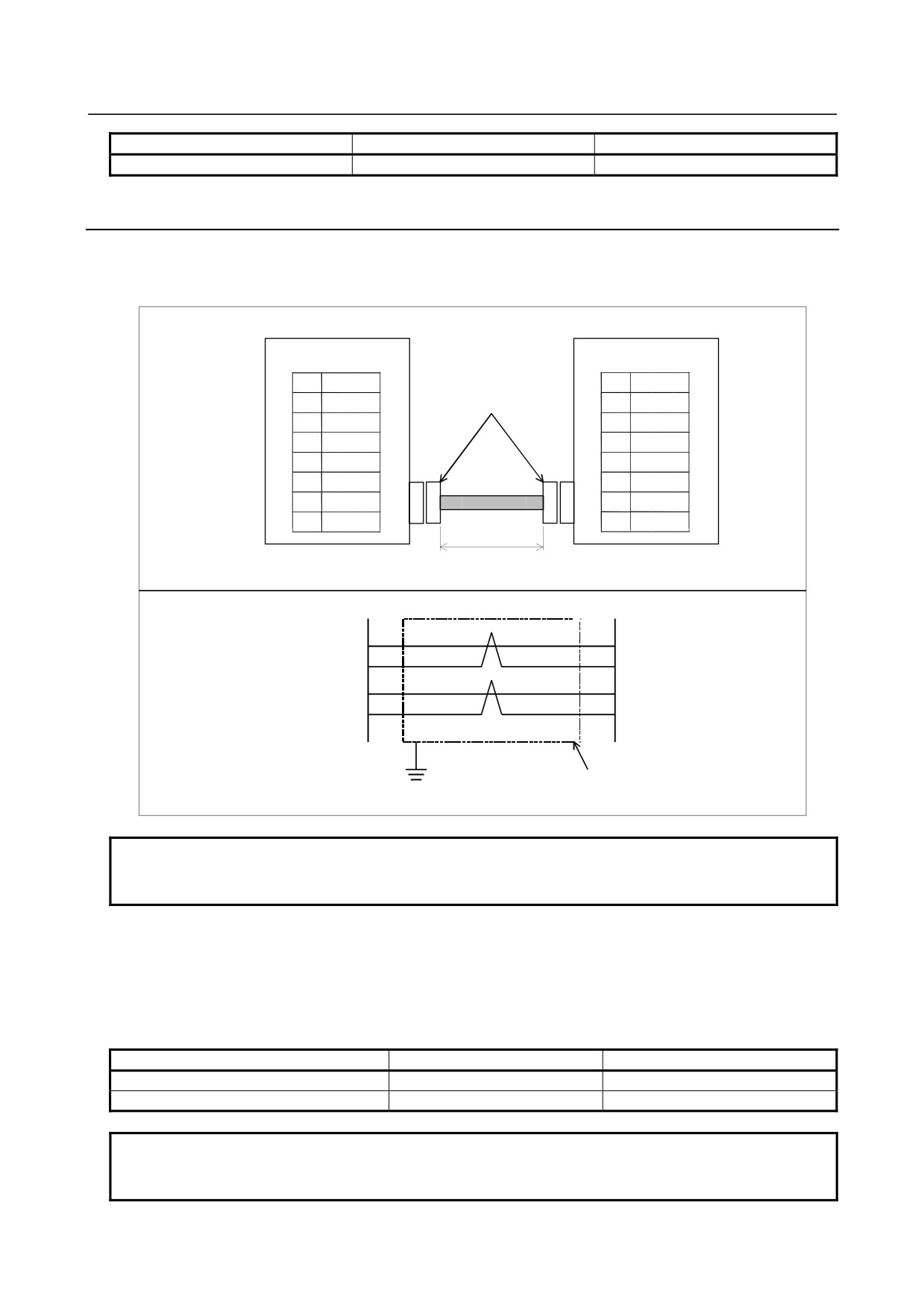
The connectors of a cable for connecting between the 100BASE-TX interface (CD38A) and the hub have
the pin arrangement shown below.
CD38A
HUB
1
TX+
1
TX+
2
TX-
RJ-45 modular jack
2
TX-
3
RX+
3
RX+
4
4
5
5
6
RX-
6
RX-
7
7
8
8
Max. 100m
CD38A
1
1
TX+
TX+
2
2
TX-
TX-
3
3
RX+
RX+
6
6
RX-
RX-
Shield
NOTE
The cable can be up to 100 m long (for the FANUC- recommended cable for
movable sections, up to 50 m). Do not make the cable longer than necessary.
Cable Wires
Many cables without a shield (UTP cables) are commercially available as twisted pair cables conforming
to
10BASE-T or 100BASE-TX. To improve noise immunity in factory automation environments,
however, be sure to use twisted pair cables (STP cables) with a common shield in category 5.
Recommended cables (for fixed parts)
Manufacturer
Specification
Remark
Furukawa Electric Co., Ltd.
DTS5087C-4P
Twisted wires
Nissei Electric Co., Ltd.
F-4PFWMF
Single-wire cable
NOTE
No cable recommended for use in fixed sections shall be used in movable
sections. Be sure to use the following movable-section cables.
- 64 -
B-64303EN/03
5.CONNECTION TO CNC PERIPHERALS
Recommended cable (for movable sections)
Manufacturer
Specification
Remark
Oki Electric Cable Co., Ltd.
AWG26 4P TPMC-C5-F(SB)
Dedicated to FANUC products
Cable specification (FANUC original product, with no connector)
Drawing number: A66L-0001-0453
Manufacturer:
Oki Electric Cable Co., Ltd.
Specification
-
Electrical characteristic:
Complying with EIA/TIA 568A categories 3 and 5
The length of the cable to the hub must be kept within 50 m because of its attenuation
performance.
-
Structure: Common-shield braided cable with drain wire
The conductors of the cable are AWG26 annealed-copper strand wire, with a sheath 0.8 mm
thick and an outer diameter of 6.7 ± 0.3 mm
-
Fire resistance: UL1581 VW-1
-
Oil resistance:
As per FANUC's internal standard (Equivalent to conventional oil-resistant electrical cable)
-
Flex resistance:
Million or more bending cycles with a bending radius of 50 mm (U-shaped bend test)
-
UL style No.: AWM20276 (80°C/30V/VW-1)
NOTE
Use the TM21CP-88P(03) connector made by Hirose Electric Co., Ltd. to this
cable.
About cable assemblies
Oki Electric Cable Co., Ltd. can offer a cable assembly that uses the TM21CP-88P(03) connector made
by Hirose Electric Co., Ltd. To get this cable assembly, negotiate directly with the manufacturer on its
specifications (cable length, shipping test, package, etc.).
Connector specification
An 8-pin modular connector called the RJ-45 is used with a twisted-pair cable for Ethernet interfaces.
Use the connector listed below or equivalent.
Specification
Manufacturer
Remark
Connector used with cable AWG26 4P TPMC-C5-F(SB)
TM21CP-88P(03)
Hirose Electric Co., Ltd.
(Note)
NOTE
About TM21CP-88P(03)
Connector (manufacturer's standard product)
Drawing number: A63L-0001-0823#P
Manufacturer: Hirose Electric Co., Ltd.
Manufacturer's model number: TM21CP-88P(03)
Complying with EIA/TIA 568A categories 3 and 5
Ask Hirose Electric Co., Ltd. for explanations about how to attach the connector
to a cable.
(Hirose Electric Co., Ltd. offers the TM21CP-88P(03) Wiring Procedure Specification (Engineering
Specification No. ATAD-E2367) to explain the related technical information.)
- 65 -

5.CONNECTION TO CNC PERIPHERALS
B-64303EN/03
5.4.3
Anti-Noise Measure
Separating signal lines
Ethernet cable wires belong to group C. See descriptions elsewhere for explanations about how to
separate them from wires in group A or B.
Cable clamp and shield processing
If any cable led into the CNC requires shielding, clamp it as shown below. The same method is used
also to shield Ethernet twisted-pair cables. The clamp shown in the figure works not only for cable
fixing but also for shield processing. Shield processing is very important to maintain the stable
operation of the system. Do not forget attach this clamp. See Subsection 3.5.1.3 "Cable Clamp and
Shield Processing," for details.
5.4.4
Network Installation
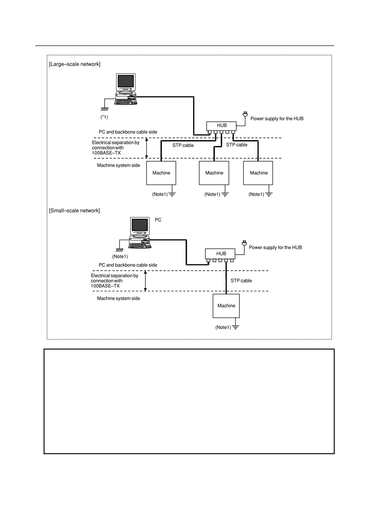
Even when the machine satisfies its grounding requirements, noise from the machine may get on
communication lines depending on the way the machine is installed and its environment, resulting in a
communication error. Separating and isolating the Ethernet backbone cable and PC from the machine
can prevent noise from getting on the communication lines.
An example of connection is shown below.
- 66 -
B-64303EN/03
5.CONNECTION TO CNC PERIPHERALS
NOTE
1 Ground the PC and backbone cable separately from the machine system.
If this is impossible because there is only one grounding point, use separate
grounding wires for the PC/backbone cable and the machine system up to the
grounding point.
The grounding resistance must not be higher than 100 Ω (class 3 grounding).
The grounding wire must not be thinner than the AC power line conductor, and
its cross-sectional area must not smaller than 5.5 mm2.
2 In some cases, the aforementioned isolation/separation method based on
100BASE-TX cannot assure normal communication because of influence by
noise. In such worst environments, use optical fiber media to completely isolate
the machine from the PC.
- 67 -
5.CONNECTION TO CNC PERIPHERALS
B-64303EN/03
5.5
CONNECTION TO THE TOUCH PANEL
5.5.1
Connection of the LCD Unit with a Touch Panel
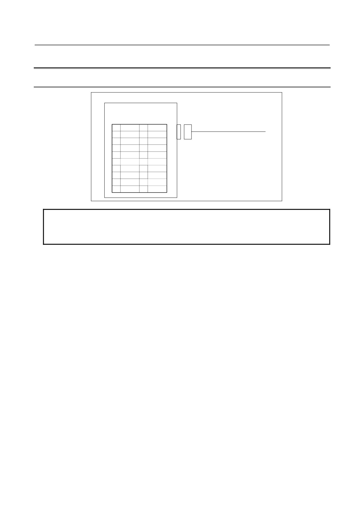
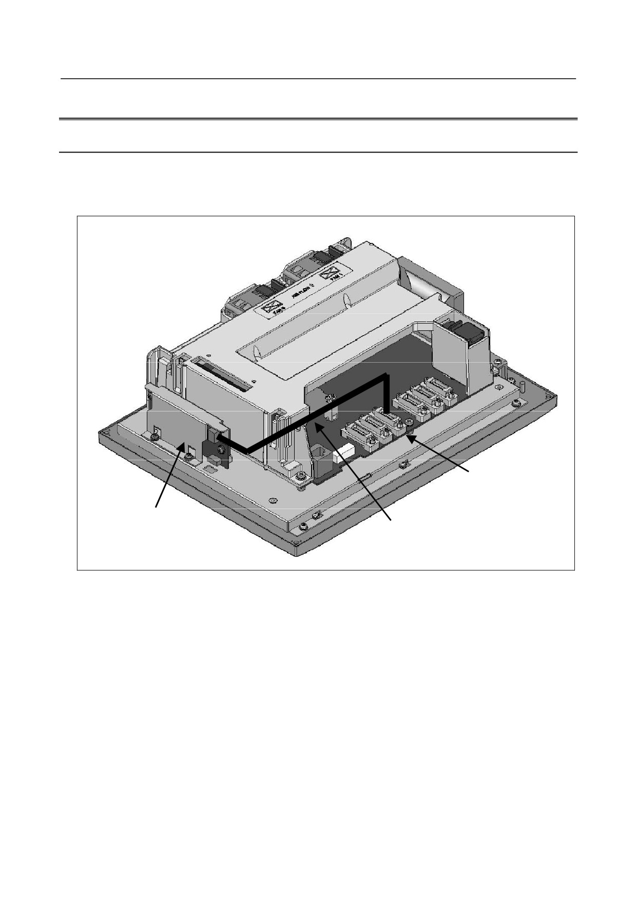
When the LCD unit with a touch panel is used, RS232C serial port 2CH (JD36B) cannot be used as a
general-purpose port because it is used for touch panel communication. Since the touch panel
communication cable is routed before shipment from FANUC, the tool builder does not need to route it.
R232-2
JD36B
Touch panel I/F
Touch panel communication cable
(Routed before shipment from FANUC)
- 68 -
B-64303EN/03
5.CONNECTION TO CNC PERIPHERALS
5.5.2
External Touch Panel Interface
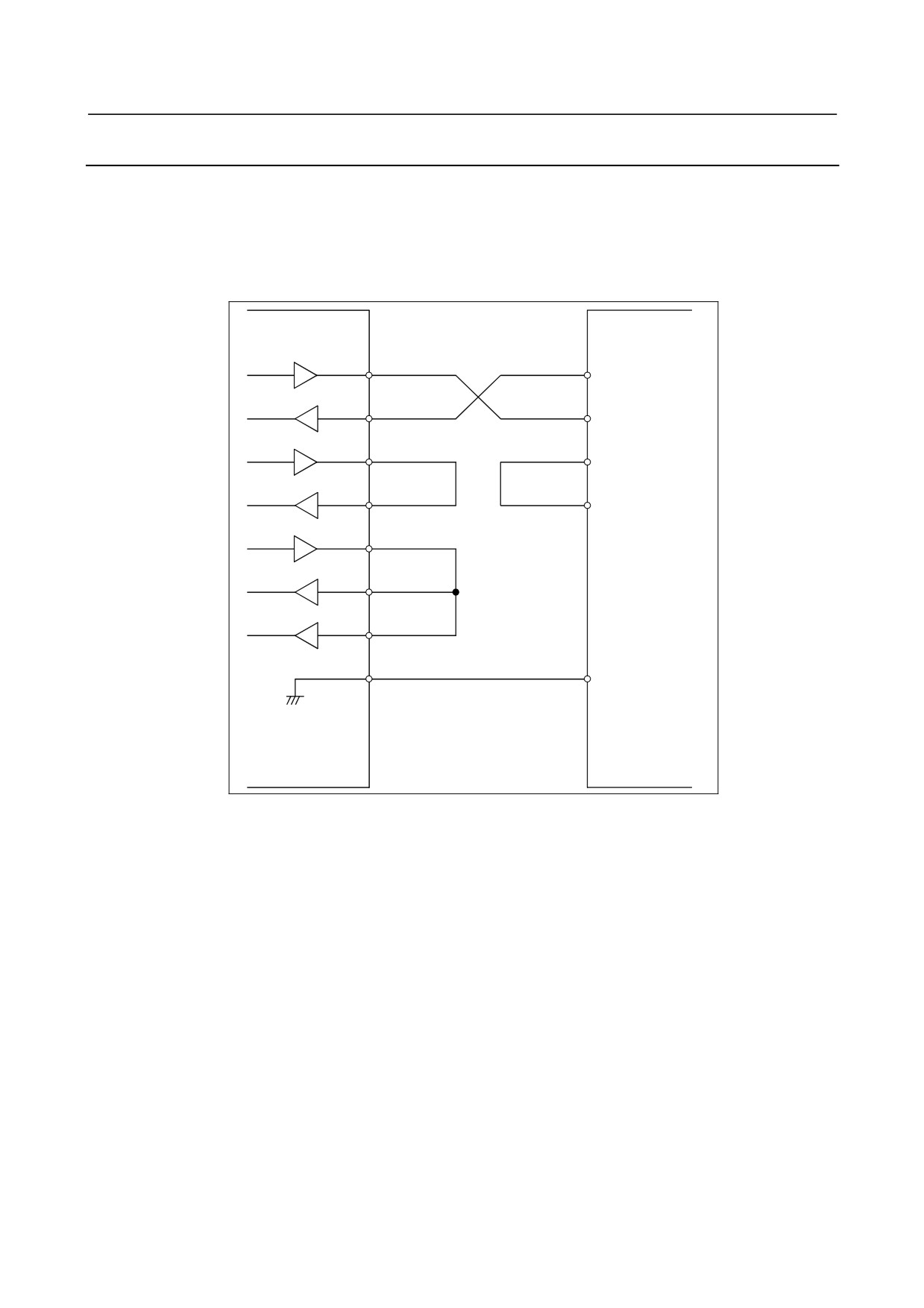
The external touch panel interface function can be used to connect to the external touch panel that
supports the SNP-X protocol. In this case, RS232C serial port 2CH (JD36B) is used to connect between
the CNC and the external touch panel.
Connection cable
The connection diagram is shown below.
NC side
External touch panel
JD36B
side
SD (11)
SD
RD (1)
RD
RS (15)
RS
CS (5)
CS
ER (13)
DR (3)
CD (7)
0V (4,6,8,14,16)
SG
- 69 -
5.CONNECTION TO CNC PERIPHERALS
B-64303EN/03
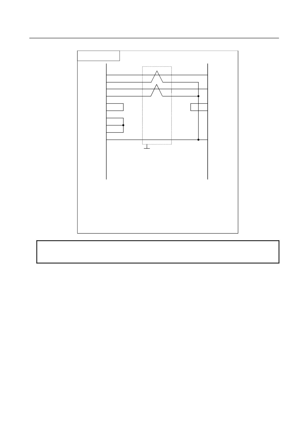
The connection cable needs to be created as shown below.
Cable connection
JD36B
11
SD
RD
12
0V
1
RD
SD
2
0V
15
RS
RS
5
CS
CS
3
DR
7
CD
13
ER
4,6,8,14,16
0V
SG
Shield
Grounding
plate
Recommended cable specification
A66L-0001-0284#10P (#28AWG × 10 pairs)
Recommended connector specification
PCR-E20FA (Honda Tsushin Kogyo Co., Ltd.)
FI30-20S (Hirose Electric Co., Ltd.)
FCN-247J020-G/E (Fujitsu, Ltd.)
52622-2011 (Molex Japan Co., Ltd.)
FI40B-2015S (Hirose Electric Co., Ltd.)
NOTE
Recommended cable connector FI30-20S (Hirose Electric) cannot be used for
the stand-alone type.
- 70 -
B-64303EN/03
6.SPINDLE CONNECTION
6 SPINDLE CONNECTION
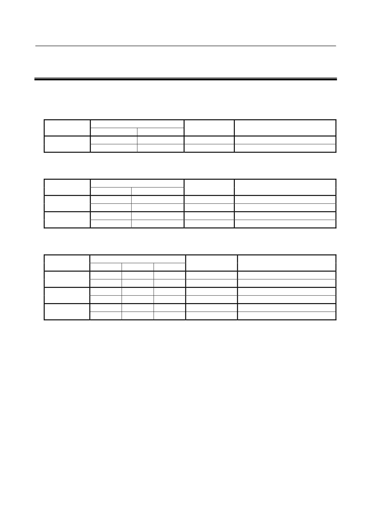
The figure below shows the spindle-related connections. Note that the number of connectable spindles
depends on the model. So, see the tables that follow the figure below.
For Series 0i Mate
Number of
Serial spindle
Analog spindle
Position coder for analog spindle
spindles
First
Second
○
1
○
Usable
The spindles marked with ○ are to be selected.
For Series 0i (1-path control)
Number of
Serial spindle
Analog spindle
Position coder for analog spindle
spindles
First
Second
○
1
○
Usable
○
○
2
○
○
Unusable
The spindles marked with ○ are to be selected.
For Series 0i (2-path control)
Number of
Serial spindle
Analog spindle
Position coder for analog spindle
spindles
First
Second
Third
○
1
○
Usable
○
○
2
○
○
Unusable
○
○
○
3
○
○
○
Unusable
The spindles marked with ○ are to be selected.
When using third serial spindle, the serial spindle connector panel is necessary.
- 71 -
6.SPINDLE CONNECTION
B-64303EN/03
(1)
Position coder
Spindle Amp. (first)
JA7A-1
JA7B
(2)
(Channel 1)
JA41
TB2
JA48
JA7A-2
JA7A
Spindle motor
(3)
(Channel 2)
Serial spindle
Position coder
connector
Spindle Amp.(second)
panel
JA7B
JA7A TB2
CNC
Main
Spindle motor
board
Position coder
Spindle Amp. (first)
JA7B αi SP
JA7A TB2
Spindle motor
Position coder for analog spindle
Inverter
JA40
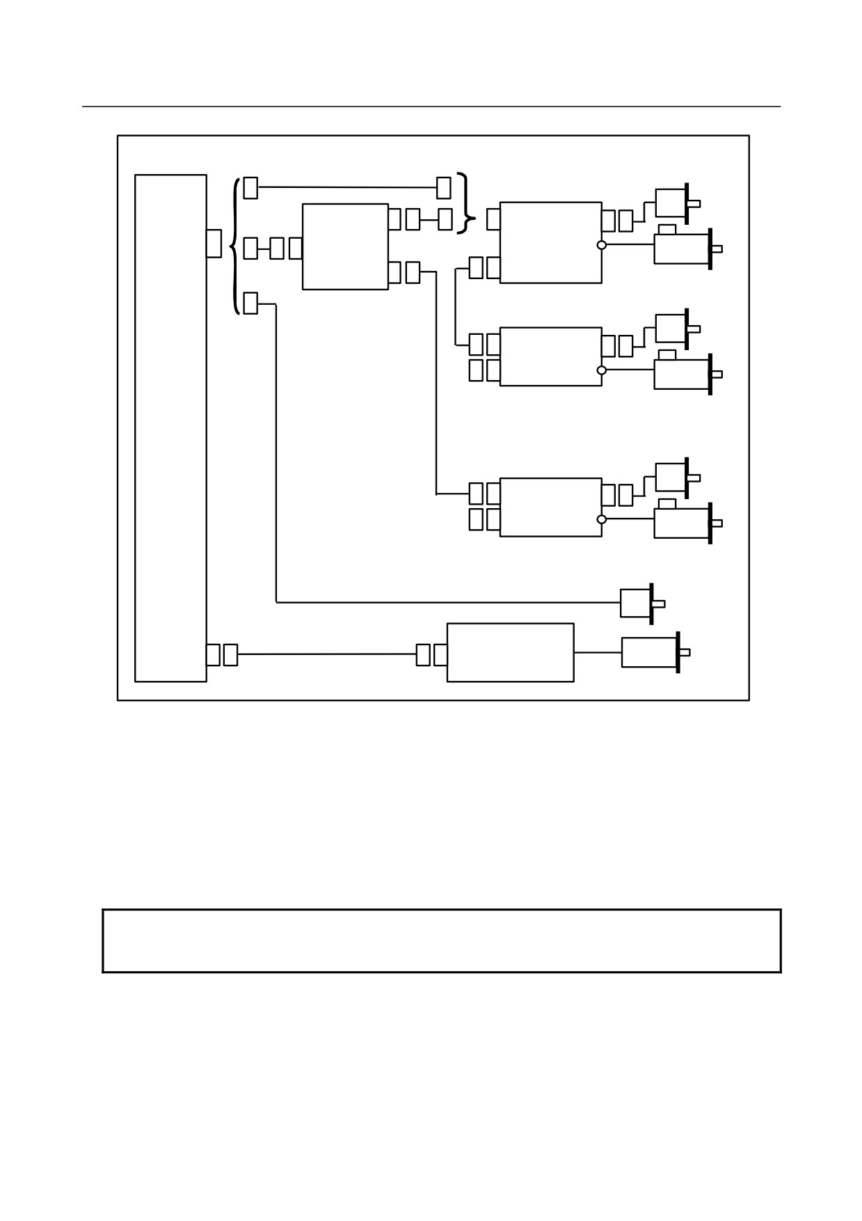
Analog spindle
(1) To use one serial spindle, make a direct connection from JA41 on CNC to the spindle amplifier. And,
to two serial spindles, make a direct connection from JA7A on the first amplifier to the second
spindle amplifier.
(2) To use third serial spindle, make a connection from JA41 on CNC to the serial spindle connector
panel for a branch. And, make a connection from JA7A-1 on the serial spindle connector panel for a
branch to the first spindle amplifier, make a connection from JA7A-2 on the serial spindle connector
panel for a branch to the third spindle amplifier
(3) To use the position coder for an analog spindle, make a direct connection from JA41 to the position
coder.
NOTE
When using the serial spindle interface, the position coder interface for analog
spindles cannot be used.
- 72 -
B-64303EN/03
6.SPINDLE CONNECTION
6.1
SERIAL SPINDLE
6.1.1
Connection of One to Two Serial Spindles
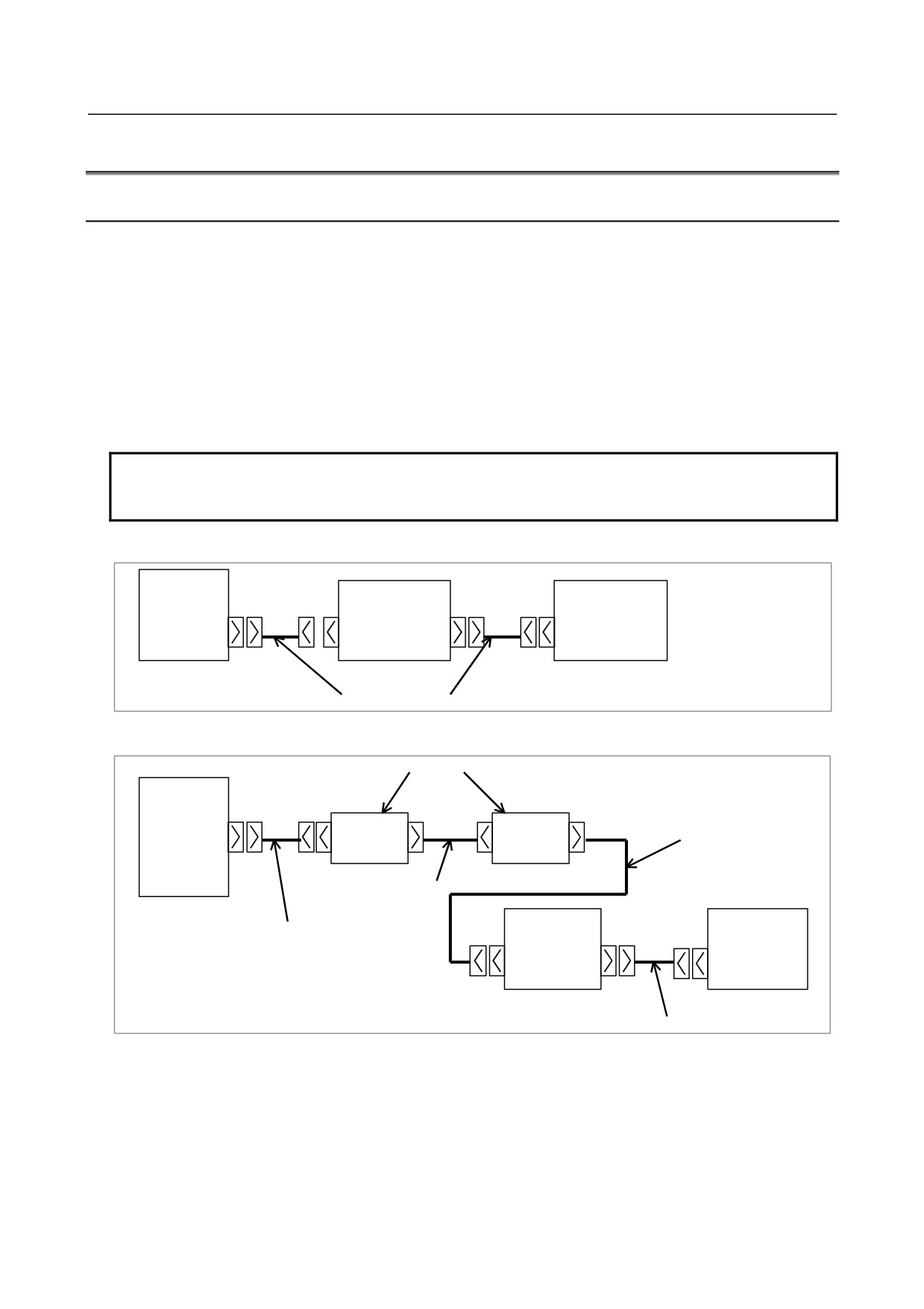
When connecting one serial spindle amplifier, connect it to JA41. When connecting a second serial
spindle amplifier, connect it to JA7A of the first serial spindle amplifier.
Electric cables are usually used to connect serial spindles, but optical fiber cables and optical adapters
need to be used when:
-
The cable length is 20 m or more.
-
A ground wire with a cross-sectional area of 5.5 mm2 or more cannot be used to connect between
the power magnetics cabinet having spindle amplifiers installed and the operator's panel cabinet
having the CNC control unit installed.
-
Cables may be significantly affected by noise. For example, when there is a strong electromagnetic
noise generator such as a welding machine near the cables or when the cables runs long in parallel
with a power line that generates noise or a power magnetic cable
NOTE
The conventional optical I/O Link adapter (A13B-0154-B001) cannot be used.
Use optical adapter (A13B-0154-B003).
Connection diagram (when only electric cables are used)
CNC
Spindle amplifier
Spindle amplifier
JA41
JA7B
JA7A
JA7B
JA7A
Interconnection cable 1
Connection diagram (when an optical cable is used)
Optical adapter
CNC
JD1
JD1
Interconnection cable 2
JA41
COP1
COP1
Optical cable
Spindle amplifier
Spindle amplifier
Interconnection cable 2
JA7B
JA7B
JA7A
JA7A
Interconnection cable 1
- 73 -
6.SPINDLE CONNECTION
B-64303EN/03
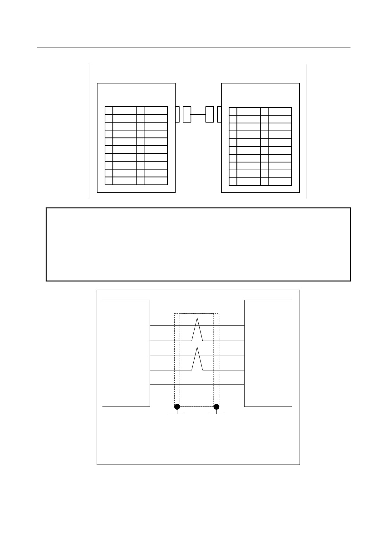
Interconnection cable 1
CNC, spindle amplifier, serial
Spindle amplifier
spindle connector panel
JA41(FI80-20P, DF1R020WB1)
JA7B
JA7A(PCR-EV20MDT)
JA7A-1,2(PCR-E20MD)
PCR-EV20MDT
1
SIN
11
1
SIN
11
0V
2
*SIN
12
0V
2
*SIN
12
0V
3
SOUT
13
3
SOUT
13
0V
4
*SOUT
14
0V
4
*SOUT
14
0V
5
[
]
15
[
]
5
15
0V
6
[
]
16
0V
6
16
0V
7
[
]
17
[
]
7
17
8
[
]
18
(+5V)
8
18
(+5V)
9
(+5V)
19
[
]
9
(+5V)
19
10
[
]
20
(+5V)
10
20
(+5V)
NOTE
1 When an optical cable is used for connection between the NC and a spindle
amplifier, the +5V signals indicated in parentheses are used to feed power to the
optical adapter.
2 The signals indicated in angle brackets [
] are reserved for functional
expansion, so no connection to them is allowed.
3 The upper connector specification of JA41 is for the LCD-mounted type.
The lower connector specification is for the stand-alone type.
Cable connection
Connectors
Connector JA7B
JA41
JA7A
3
1
SIN
SOUT
JA7A-1,2
4
2
*SIN
*SOUT
CNC, spindle
Spindle
1
3
amplifier, serial
SIN
SOUT
amplifier
spindle
connector
2
4
*SIN
*SOUT
panel
12,14,16
12,14,16
0V
0V
Ground plate
Ground plate
Recommended cable connector:
PCR-E20FA (manufactured by Honda Tsushin Kogyo)
FCN-247J020-G/E (manufactured by Fujitsu)
52622-2011 (manufactured by Molex Japan)
Recommended wire specification: A66L-0001-0284#10P (#28AWG × 10 pairs)
- 74 -
B-64303EN/03
6.SPINDLE CONNECTION
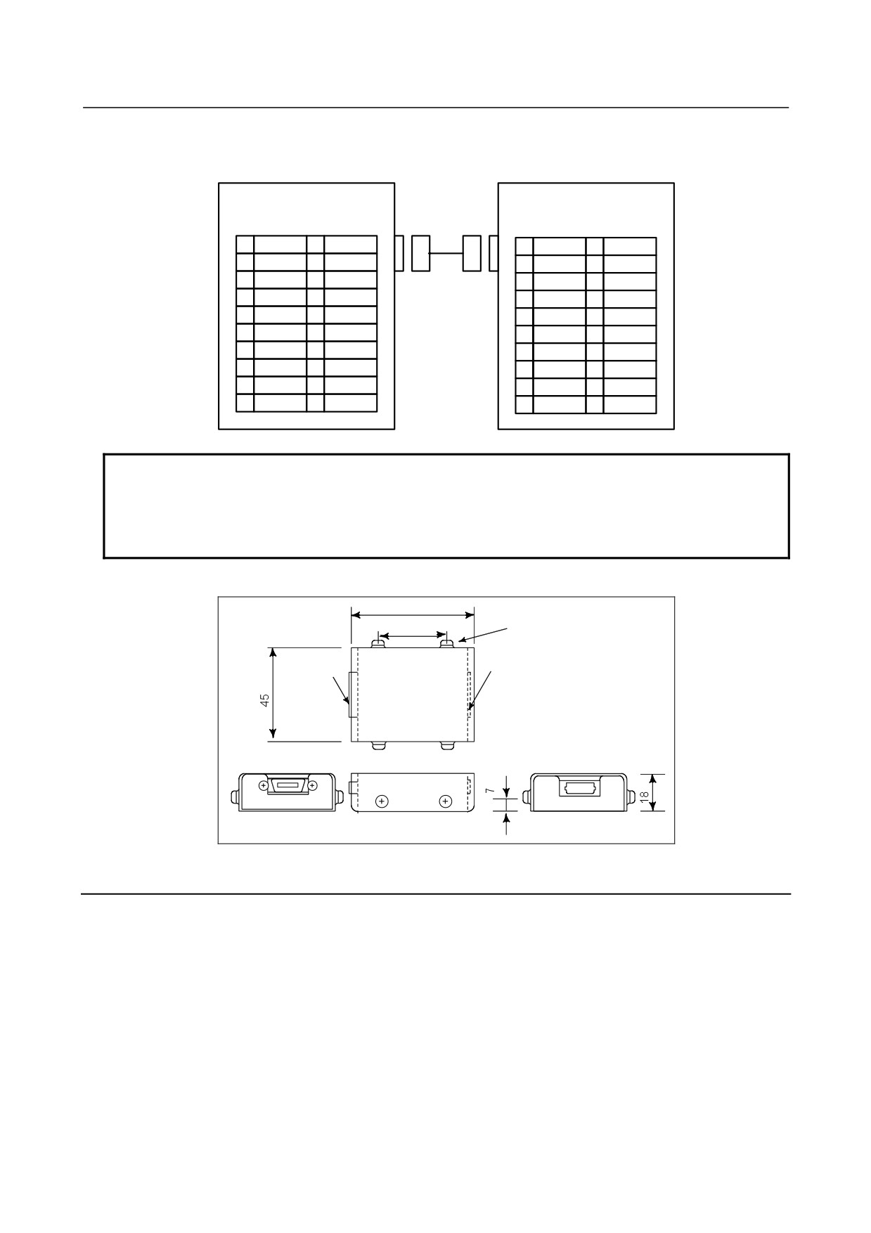
Interconnection cable 2
CNC, spindle amplifier, serial
Optical adapter
spindle connector panel
JA41(FI80-20P, DF1R020WB1)
JA7B(PCR-EV20MDT)
JD1
JA7A-1,2(PCR-E20MD)
PCR-E20LMDT
1
SIN
11
1
SIN
11
0V
2
*SIN
12
0V
2
*SIN
12
0V
3
SOUT
13
3
SOUT
13
0V
4
*SOUT
14
0V
4
*SOUT
14
0V
5
[
]
15
[
]
5
15
0V
6
[
]
16
0V
6
16
0V
7
[
]
17
[
]
7
17
8
[
]
18
+5V
8
18
+5V
9
+5V
19
[
]
9
+5V
19
10
[
]
20
+5V
10
20
+5V
NOTE
1 The signals indicated in angle brackets are reserved for functional expansion, so
no connection to them is allowed.
2 The upper connector specification of JA41 is for the LCD-mounted type.
The lower connector specification is for the stand-alone type.
Outline drawing of an optical adapter
66
40
4-M3
Connector for
connecting a
Optical
unit
connector
JD1
FANUC
COP1
Ground plate
Unit: mm
6.1.2
Connecting Three Serial Spindles
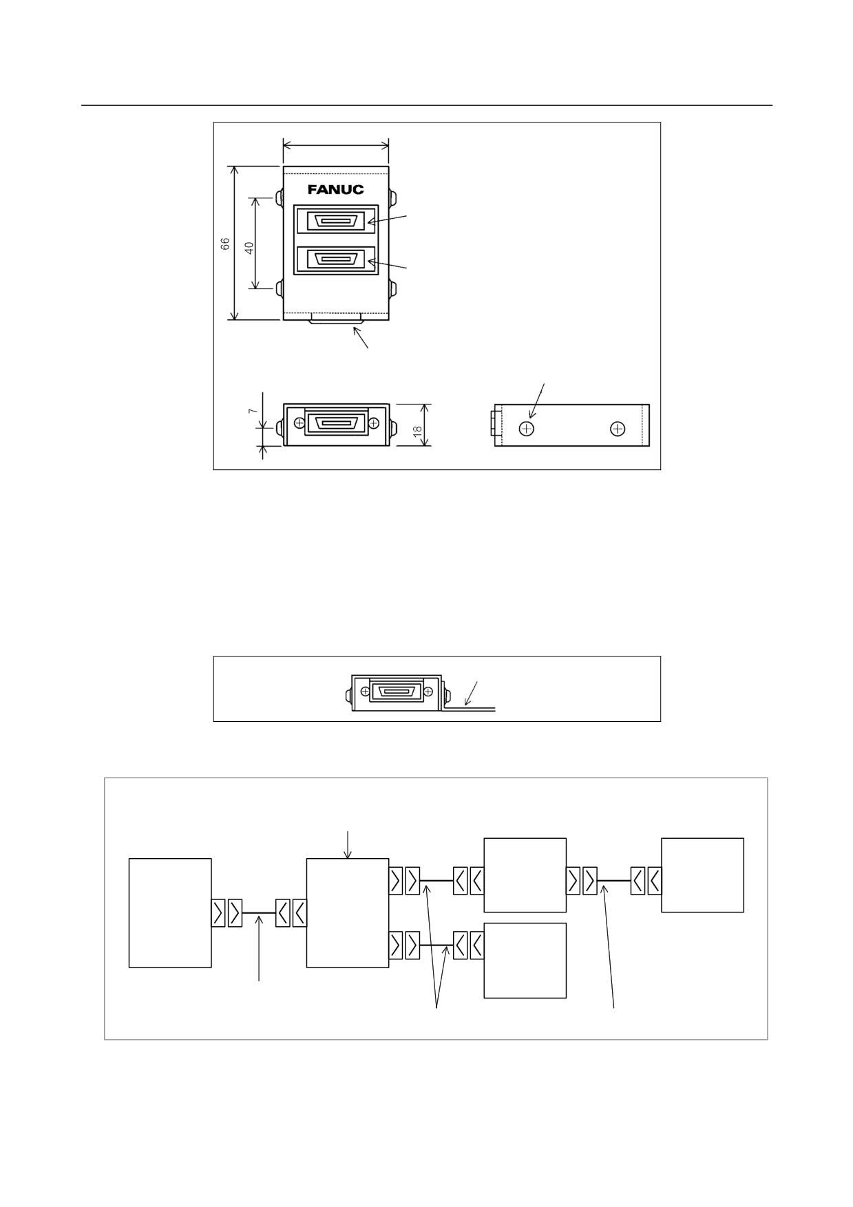
When three serial spindles are connected, the serial spindle connector panel is necessary.
Serial spindle connector panel specification: A13B-0180-B001
Outside dimensions of the serial spindle connector panel
The outside dimensions of the serial spindle connector panel are the same as those for the optical adapter
(A13B-0154-B003).
- 75 -
6.SPINDLE CONNECTION
B-64303EN/03
45
Connector for connection with a spindle
amplifier JA7A-2 (second channel)
Connector for connection with a spindle
amplifier JA7A-1 (first channel)
Connector for connection with the CNC
JA48
4-M3
Conditions for installing the serial spindle connector panel
• The serial spindle connector panel does not have an enclosed structure. So, install the serial spindle
connector panel in an enclosed cabinet as used for the CNC.
• Ground the case by using the case mounting screws of the serial spindle connector panel.
• The serial spindle connector panel is light, so that it need not be secured with screws. However,
ensure that the serial spindle connector panel does not contact other electrical circuits and thus cause
a short circuit. When securing the serial spindle connector panel to the cabinet, for example, attach
an L-shaped metal fitting as shown below with a case mounting screw (M3) of the serial spindle
connector panel.
L-shaped metal
fitti
Connection diagram
(Connection diagram when only electrical cables are used)
Serial spindle
connector panel
Spindle amplifier
Spindle amplifier
CNC
JA7B
JA7B
JA7A-1
JA7A
JA7A
JA48
JA41
JA7B
JA7A-2
JA7A
Spindle amplifier
Interconnection cable 3
Interconnection cable 1
Interconnection cable 1
- 76 -