FANUC Series 16 / 160 / 18 / 180 – Model B. Maintenance Manual - page 14
B-62445E/03
8.TROUBLESHOOTING
A16B-3200-0110
A16B-2202-0860
(1)
(1)(2)
(3)
(4)
(5)(6)
(7)
(2)
(3)
(4)
(5)
(6)
(8)(9)
(7)
(8)
(10)
(9)
(11)
(10)
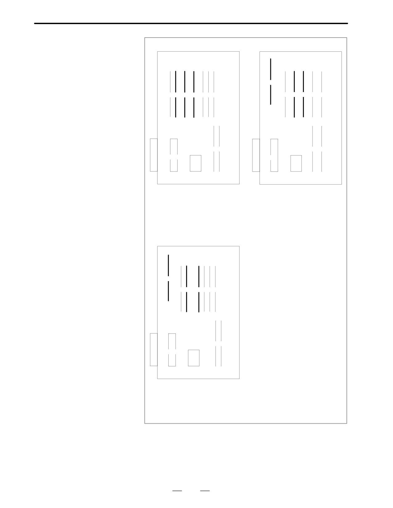
(2) FROM module
(1) DRAM module
Specification
: A20B-2902-0341,0343
Specification
: A20B-2901-0940X0942
(3) DRAM module
(3) FROM module
Specification
: A20B-2901-0940X0942
Specification
: A20B-2902-0341,0343
(4) PMC control module
: A20B-2902-0410X0411
Specification
: A20B-2901-0960X0961
(4) PMC control module
Specification: A20B-2901-0960X0961
A16B-3200-0160
(1)
(2)
(3)
(4) (5) (6) (7)
(8)
(9)
(10)
(11)
(1) DRAM module
Specification
: A20B-2901-0940X0942
(3) FROM module
Specification
: A20B-2902-0341,0343
A20B-2902-0410X0411
(4) PMC control module
Specification
: A20B-2901-0960X0961
393
8. TROUBLESHOOTING
B-62445E/03
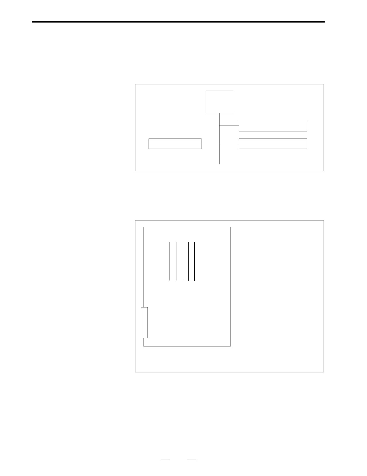
A watch dog alarm has generated in PMC-RC.
8.37
ALARM 951 (PMC-RC
WATCH DOG ALARM)
Causes and Remedies
Option 3 board or a module on the option 3 board
(5)
PMC-RC
CPU
PMC-RC User program
(1)
(3)
DRAM module
PMC control
(4)
⋅
Option 3 board is faulty.
⋅
PMC DRAM module (4) is faulty.
⋅
PMC control module (5) is faulty.
Module mounting
(Option 3 board)
position
(1)
(2)
(3)(4)
(5)
(4) PMC DRAM module
A20B-2902-0191 to A20B-2902-0198
(5) PMC control module
A20B-2901-0960 to A20B-2901-0961
394
B-62445E/03
8.TROUBLESHOOTING
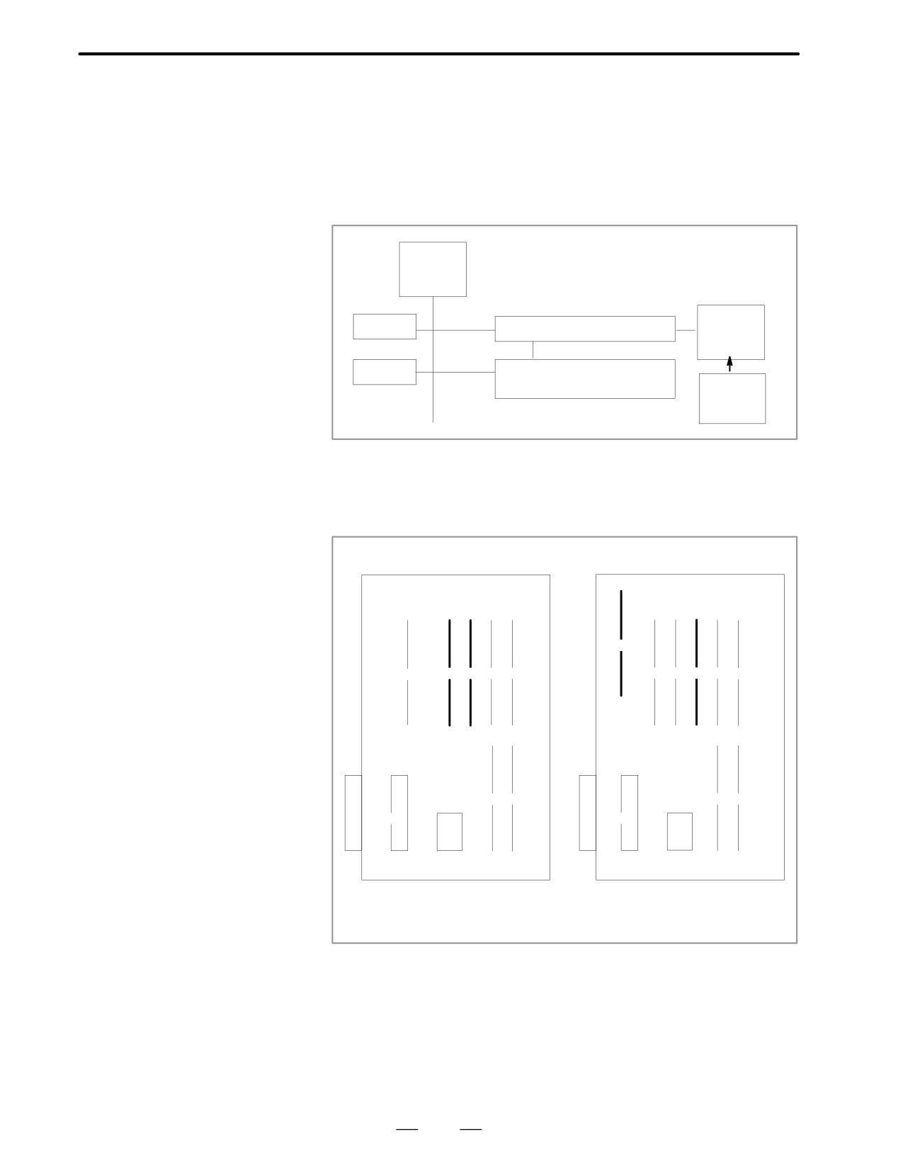
RAM parity error or NMI has occurred in the PMC control module.
8.38
ALARM 970 (NMI
ALARM IN PMC
CONTROL MODULE)
Causes and Remedies
Fault of PMC module is considered.
Main
CPU
<PMC module>
FANUC
ROM
PMC control
I/O
unit
RAM
PMC-RA or
PMC-RB user program
+24V
power
supply
⋅
PMC control module (3) is faulty.
⋅
DRAM module (9) is faulty.
Module mounting
position
A16B-3200-0010
A16B-3200-0170
(1)
(1)
(2)
(3)
(4)
(5)
(2)
(3)
(4)
(5)
(6)
(6)
(7)
(7)
(8)
(8)
(9)
(9)
(10)
(2) DRAM module
(1) DRAM module
Specification
: A20B-2901-0940X0942
Specification
: A20B-2901-0940X0942
(3) PMC control module
(4) PMC control module
Specification
: A20B-2901-0960X0961
Specification
: A20B-2901-0960X0961
395
8. TROUBLESHOOTING
B-62445E/03
A16B-3200-0110
A16B-2202-0860
(1)
(1)(2)
(3)
(4)
(5)(6)
(7)
(2)
(3)
(4)
(5)
(6)
(8)(9)
(7)
(8)
(10)
(9)
(11)
(10)
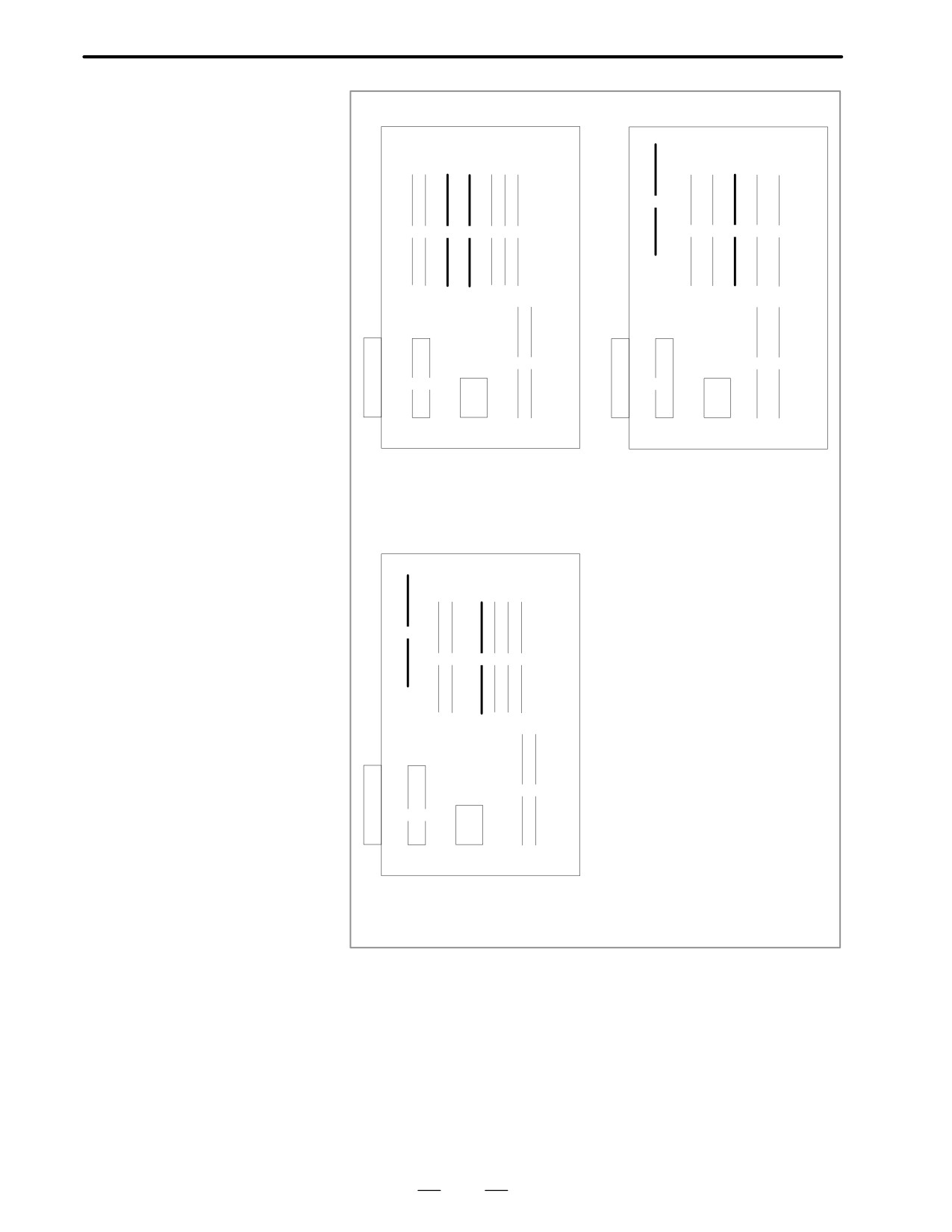
(3) DRAM module
(1) DRAM modle
Specification
: A20B-2901-0940X0942
Specification
: A20B-2901-0940X0942
(4) PMC control module
(4) PMC control module
Specification
: A20B-2901-0960X0961
Specification
: A20B-2901-0960X0961
A16B-3200-0160
(1)
(2)
(3)
(4) (5) (6) (7)
(8)
(9)
(10)
(11)
(1) DRAM module
Specification
: A20B-2901-0940X0942
(4) PMC control module
Specification
: A20B-2901-0960X0961
396
B-62445E/03
8.TROUBLESHOOTING
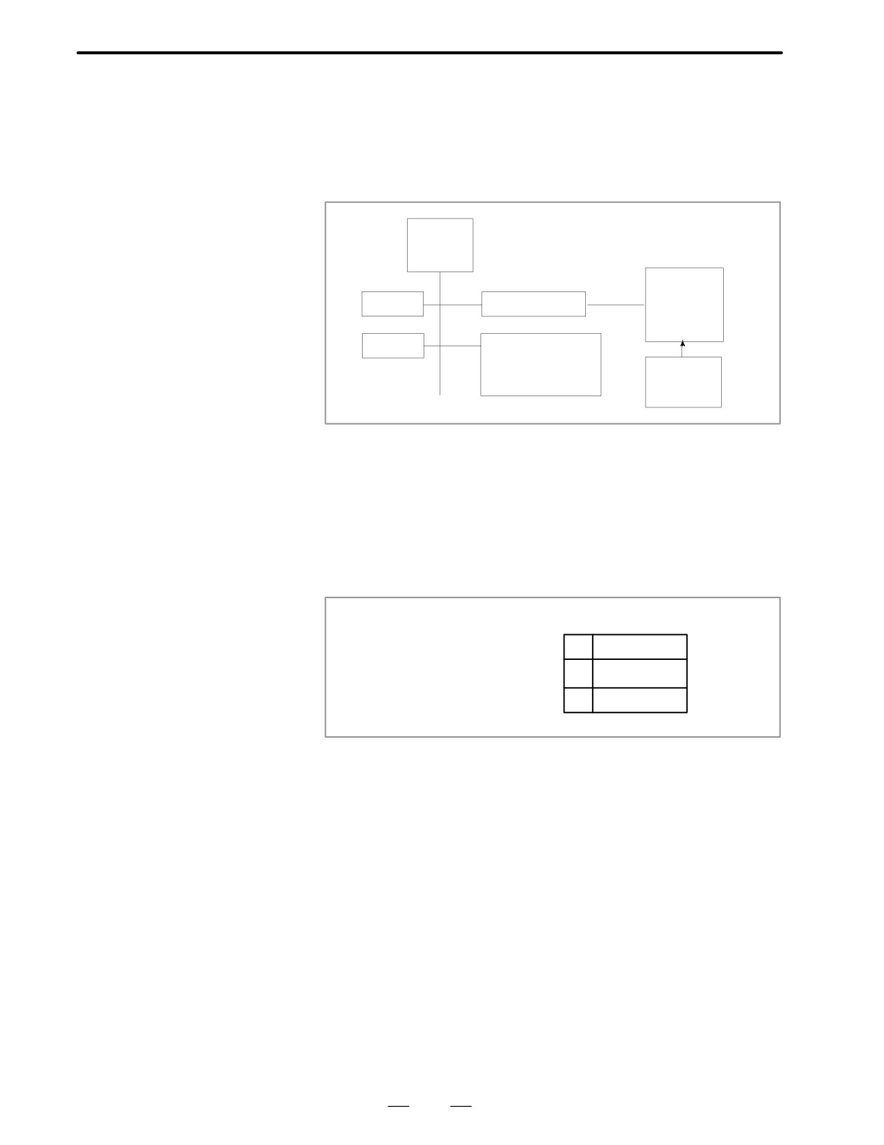
A communication error is detected between the CNC and FANUC I/O
8.39
unit at SLC in the PMC control module.
ALARM 971
(NMI ALARM IN SLC)
Causes and Remedies
Fault of PMC module or fault of FANUC I/O unit
Main
CPU
<PMC module>
FANUC
ROM
PMC control
I/O
unit
RAM
PMC-RA or
PMC-RB
+24V
user program
power
memory
supply
⋅
PMC control module (3) is faulty.
⋅
FANUC I/O unit is faulty.
⋅
+24V power to the FANUC I/O unit is faulty.
⋅
Remove connector CP32 of the interface module (AF01A,AF01B)
and
⋅
measure voltage across 1st and 2nd pins using tester.
⋅
(Normally+24VDC±10%)
Interface module
AF01A/AF01B
1
+24V
CP32
2
GND
3
Unused
Disconnection or broken of cable.
Refer to previous page for the module mounting position.
397

8. TROUBLESHOOTING
B-62445E/03
NMI has generated in a board other than the main CPU board.
8.40
ALARM 972
(NMI ALARM)
Causes and Remedies
1) Any of option boards shown below may be faulty.
⋅
Option 1 board
⋅
Option 2 board
⋅
Option 3 board
⋅
Loader control board
Change above boards in the order, in which replacement is easier.
Note
When you change option 2 board, you must input data
(parameters, programs, etc.) on sub side.
When you change loader control board, you must input data
(parameters, programs, etc.) on loader side.
398
B-62445E/03
8.TROUBLESHOOTING
An unknown NMI has generated.
8.41
ALARM 973
(NMI ALARM BY
UNKNOWN CAUSE)
Causes and Remedies
1) Main CPU board or power supply unit is faulty
⋅
Main CPU board is faulty.
⋅
Power supply unit is faulty.
Note
When the main CPU board is replaced, all the data in
memory is lost. Set the NC data (parameter, offset and
program etc) again.
2) Option boards may be faulty.
⋅
Option 1 board is faulty.
⋅
Option 2A
⋅
Option 3 board is faulty.
⋅
Loader control board is faulty
Change above boards in the order, in which replacement is easier.
Note
When you change the option 2 board, you must input data
(parameters, programs,etc.) on the sub side.
When you change loader control board, you must input data
again (parameters, programs, etc.)
399

9. TROUBLESHOOTING (SERIAL INTERFACE SPINDLE)
B-62445E/03
TROUBLESHOOTING (SERIAL INTERFACE SPINDLE)
9
This chapter describes a troubleshooting of the serial interface spindle
amplifier.
9.1 LIST OF SERIAL INTERFACE SPINDLE
AMPLIFIER ALARMS .
401
9.2 TROUBLESHOOTING FOR EACH ALARM .
404
400
B-62445E/03
9. TROUBLESHOOTING (SERIAL INTEFACE SPINDLE)
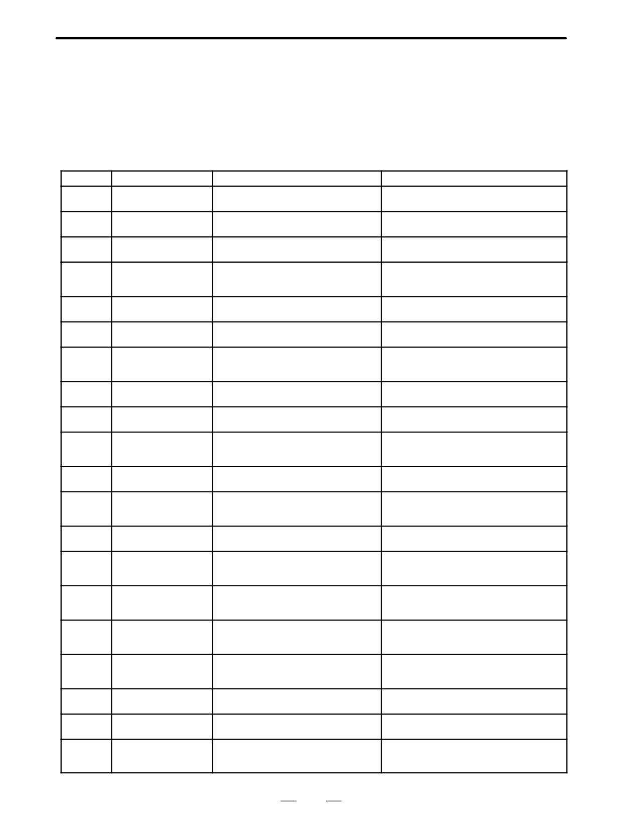
9.1
LIST OF SERIAL
INTERFACE SPINDLE
AMPLIFIER ALARMS
For troubleshooting the listed alarms, refer to
9.2
“TROUBLE
SHOOTING FOR EACH ALARM”.
Alarm No.
Meanings
Description
Remedy
Motor overheat
Detects internal motor temperature
:
Check load status.
AL-01
exceeding specified temperature.
Cool motor, then reset alarm.
Excessive speed devi-
Detects motor speed exceeding specified
Check load status.
AL-02
ation
speed excessively.
Reset alarm.
DC link section fuse
Detects that fuse F4 in DC link section is
Check power transistors, and so forth.
AL-03
blown
blown (models 30S and 40S).
Replace fuse.
Input fuse blown.
Detects blown fuse (F1 to F3), open phase
Replace fuse. Check open phase and power
AL-04
Input power open phase.
or momentary failure of power (models 30S
supply regenerative circuit operation.
and 40S).
Control power supply
Detects that control power supply fuse AF2
Check for control power supply short circuit.
AL-05
fuse blown
or AF3 is blown (models 30S and 40S).
Replace fuse.
Excessive speed
Detects that motor rotation has exceeded
Reset alarm.
AL-07
115% of its rated speed.
High input voltage
Detects that switch is set to 200 VAC when
Set switch to 230 VAC.
AL-08
input voltage is 230 VAC or higher (models
30S and 40S).
Excessive load on main
Detects abnormal temperature rise of power
Cool radiator, then reset alarm.
AL-09
circuit section
transistor radiator.
Low input voltage
Detects drop in input power supply voltage.
Correct cause, then reset alarm.
AL-10
Overvoltage in DC link
Detects abnormally high direct current
Correct cause, then reset alarm.
AL-11
section
power supply voltage in power circuit sec-
tion.
Overcurrent in DC link
Detects flow of abnormally large current in
Correct cause, then reset alarm.
AL-12
section
direct current section of power circuit.
CPU internal data
Detects abnormality in CPU internal data
Correct cause, then reset alarm.
AL-13
memory abnormality
memory. This check is made only when
power is turned on.
Spindle switch/output
Detects incorrect switch sequence in
Check sequence.
AL-15
switch alarm
spindle switch/output switch operation.
RAM abnormality
Detects abnormality in RAM for external
Correct cause, then reset alarm.
AL-16
data. This check is made only when power
is turned on.
Program ROM sum
Detects program ROM data error. This
Correct cause, then reset alarm.
AL-18
check error
check is made only when power is turned
on.
Excessive U phase
Detects excessive U phase current detec-
Correct cause, then reset alarm.
AL-19
current detection circuit
tion circuit offset. This check is made only
offset
when power is turned on.
Excessive V phase
Detects excessive V phase current detec-
Correct cause, then reset alarm.
AL-20
current detection circuit
tion circuit offset. This check is made only
offset
when power is turned on.
Serial transfer data
Detects serial transfer data error (such as
Correct cause, then reset alarm.
AL-24
error
NC power supply turned off, etc.)
Serial data transfer
Detects that serial data transfer has
Correct cause, then reset alarm.
AL-25
stopped
stopped.
Disconnection of speed
Detects abnormality in speed detection sig-
Correct cause, then reset alarm.
AL-26
detection signal for Cs
nal for Cs contouring control (such as un-
contouring control
connected cable and adjustment error).
401
9. TROUBLESHOOTING (SERIAL INTERFACE SPINDLE)
B-62445E/03
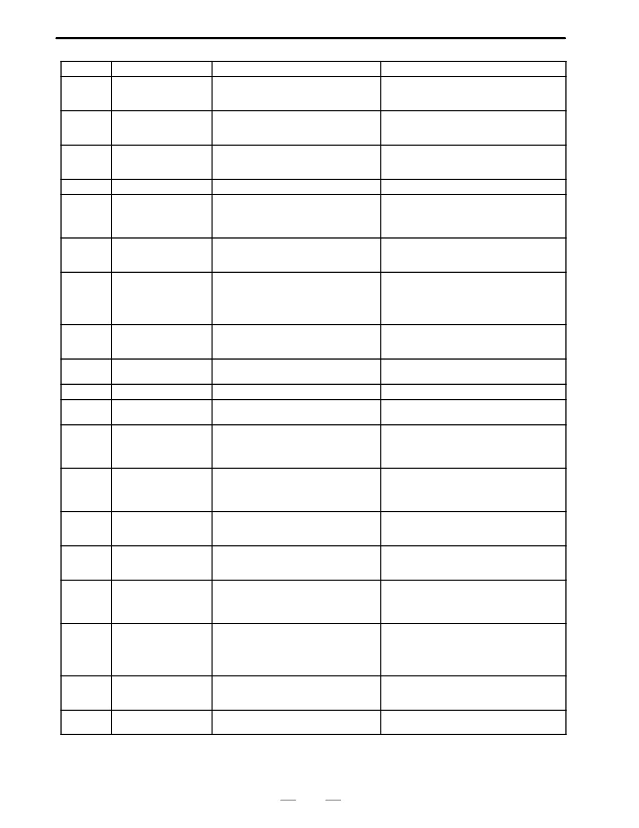
Alarm No.
Meanings
Description
Remedy
Position coder signal
Detects abnormality in position coder signal
Correct cause, then reset alarm.
AL-27
disconnection
(such as unconnected cable and parameter
setting error).
Disconnection of
Detects abnormality in position detection
Correct cause, then reset alarm.
AL-28
position detection signal
signal for Cs contouring control (such as
for Cs contouring control
unconnected cable and adjustment error).
Short-time overload
Detects that overload has been continuous-
Correct cause, then reset alarm.
AL-29
ly applied for some period of time (such as
restraining motor shaft in positioning).
AL-30
Input circuit overcurrent
Detects overcurrent flowing in input circuit.
Correct cause, then reset alarm.
Speed detection signal
Detects that motor cannot rotate at specified
Correct cause, then reset alarm.
disconnection motor
speed (but rotates at very slow speed or
AL-31
restraint alarm
has stopped). (This includes checking of
speed detection signal cable.)
Abnormality in RAM
Detects abnormality in RAM internal to LSI
Correct cause, then reset alarm.
AL-32
internal to LSI for serial
for serial data transfer. This check is made
data transfer
only when power is turned on.
Insufficient DC link
Detects insufficient charging of direct cur-
Correct cause, then reset alarm.
section charging
rent power supply voltage in power circuit
AL-33
section when magnetic contactor in amplifi-
er is turned on (such as open phase and
defective charging resistor).
Parameter data setting
Detects parameter data set beyond allow-
Set correct data.
AL-34
beyond allowable range
able range of values.
of values
Excessive gear ratio data
Detects gear ratio data set beyond allow-
Set correct data.
AL-35
setting
able range of values.
AL-36
Error counter over flow
Detects error counter overflow.
Correct cause, then reset alarm.
Speed detector parame-
Detects incorrect setting of parameter for
Set correct data.
AL-37
ter setting error
number of speed detection pulses.
Alarm for indicating fail-
Detects 1-rotation signal detection failure in
Make signal adjustment.
ure in detecting 1-rotation
Cs contouring control.
Check cable shield status.
AL-39
signal for Cs contouring
control
Alarm for indicating
Detects that 1-rotation signal has not
Make 1-rotation signal adjustment.
1-rotation signal for Cs
occurred in Cs contouring control.
AL-40
contouring control not
detected
Alarm for indicating fail-
Detects failure in detecting position coder
Make signal adjustment for signal conversion
AL-41
ure in detecting position
1-rotation signal.
circuit.
coder 1-rotation signal.
Check cable shield status.
Alarm for indicating posi-
Detects that position coder 1-rotation signal
Make 1-rotation signal adjustment for signal
AL-42
tion coder 1-rotation sig-
has not occurred.
conversion circuit.
nal not detected
Alarm for indicating
Detects that main spindle position coder
Check that main spindle position coder signal is
disconnection of position
signal used for differential speed mode is
connected to connector CN12.
AL-43
coder signal for
not connected yet (or is disconnected).
differential speed mode
Alarm for indicating fail-
Detects failure in detecting position coder
Make 1-rotation signal adjustment for signal con-
ure in detecting
1-rotation signal in thread cutting
version circuit.
AL-46
position coder 1-rotation
operation.
Check cable shield status.
signal in thread cutting
operation.
Position coder signal
Detects incorrect position coder signal
Make signal adjustment for signal conversion
AL-47
abnormality
count operation.
circuit.
Check cable shield status.
Position coder 1-rotation
Detects that occurrence of position coder
Make 1-rotation signal adjustment for signal
AL-48
signal abnormality
1-rotation signal has stopped.
conversion circuit.
402
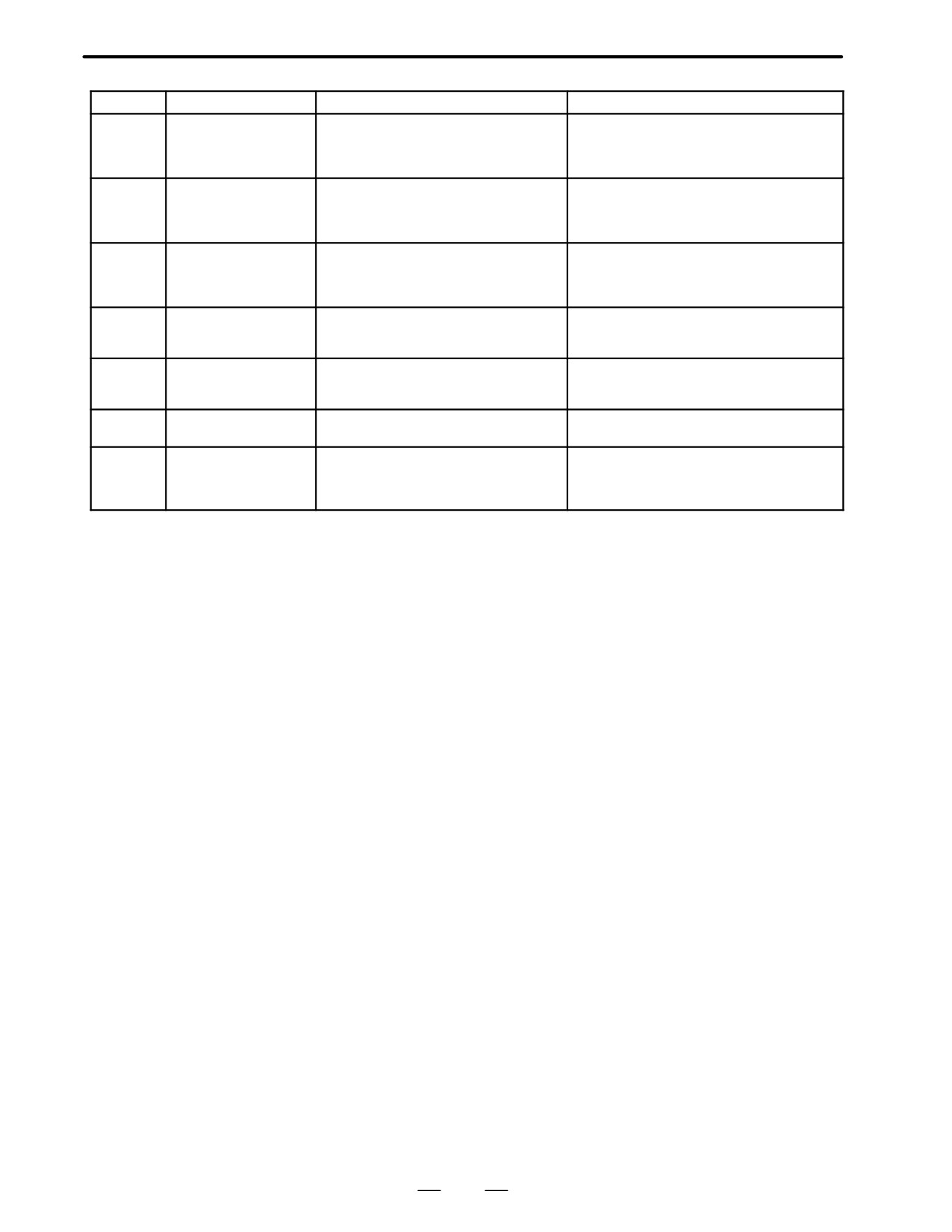
B-62445E/03
9. TROUBLESHOOTING (SERIAL INTEFACE SPINDLE)
Alarm No.
Meanings
Description
Remedy
The converted differential
Detects that difference between a spindle
Calculate differential speed by multiplying speed
speed is too high.
speed and another spindle speed has
of other spindle by gear ratio. Check if
AL-49
exceeded allowable limit in differential
calculated value is not greater than maximum
speed mode.
speed of motor.
Excessive speed
Detects that speed command calculation
Calculate motor speed by multiplying specified
command calculation
value exceeded allowable range in spindle
spindle speed by gear ratio. Check if calculated
AL-50
value in spindle
synchronization control.
value is not greater than maximum speed of mo-
synchronization control
tor.
Undervoltage at DC link
Detects that DC power supply voltage of
Correct cause, then reset alarm.
section
power circuit has dropped (due to momen-
AL-51
tary power failure or loose contact of mag-
netic contactor).
ITP signal abnormality I
Detects abnormality in synchronization sig-
Correct cause, then reset alarm.
AL-52
nal (ITP signal) with CNC (such as loss of
ITP signal).
ITP signal abnormality II
Detects abnormality in synchronization sig-
Correct cause, then reset alarm.
AL-53
nal (ITP signal) with CNC (such as loss of
ITP signal).
Overload current alarm
Detects that excessive current flowed in
Check if overload operation or frequent
AL-54
motor for long time.
acceleration/deceleration is performed.
Power line abnormality in
Detects that switch request signal does not
Check operation of magnetic contractor for
spindle switching/output
match power line status check signal.
power line switching.
AL-55
switching
Check if power line status check signal is
processed normally.
403
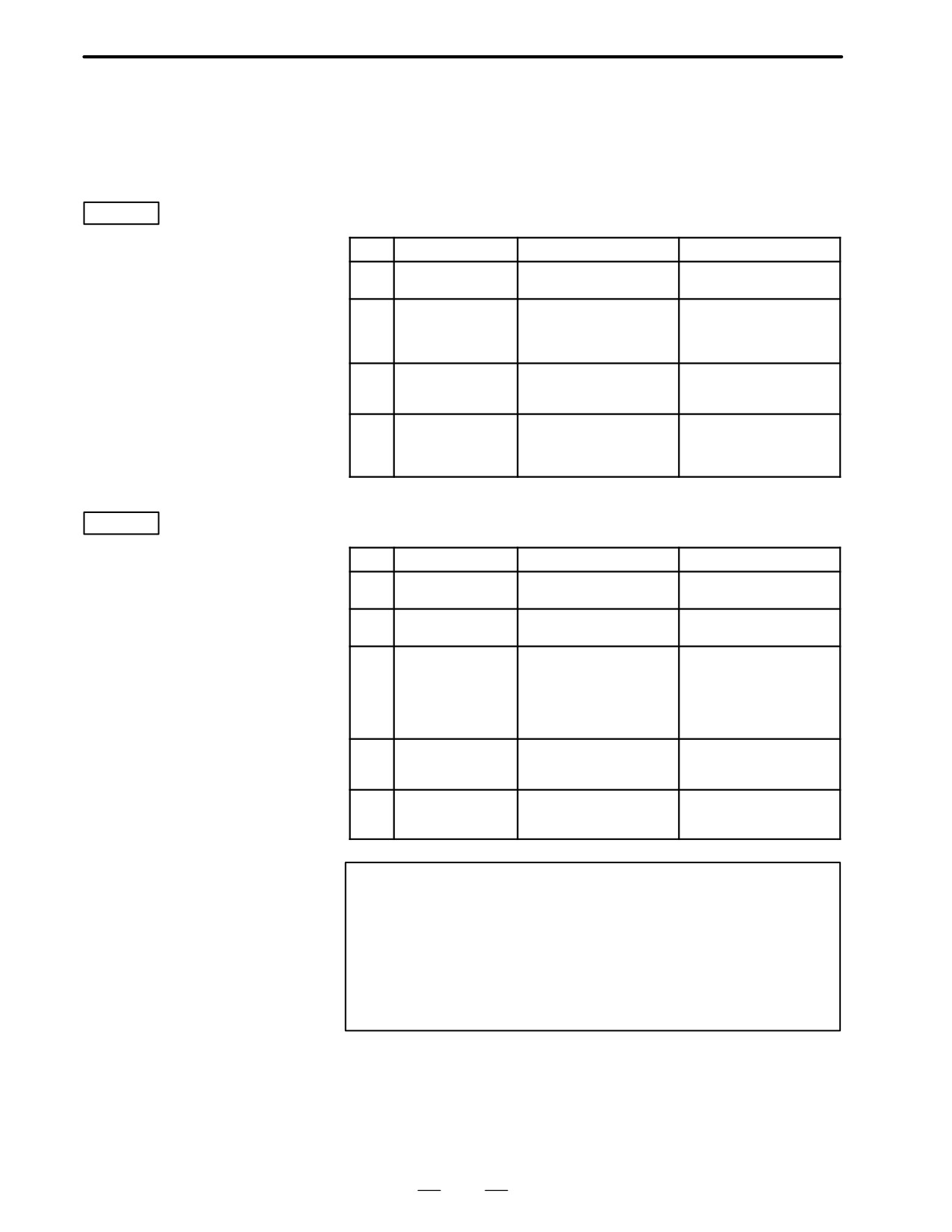
9. TROUBLESHOOTING (SERIAL INTERFACE SPINDLE)
B-62445E/03
9.2
TROUBLESHOOTING
FOR EACH ALARM
AL-01
Motor overheat
Item
Cause of trouble
Check procedure
Remedy
Defective fan motor
Check if fan motor is
Replace fan motor.
1
of motor
rotating.
Overload operation
Check cutting conditions
Review cutting conditions
and how tools are worn.
and tools.
2
Check load meter for
cutting.
Dirty motor cooling
Check motor cooling sys-
Clean motor cooling
3
system
tem for dirt.
system with an air gun or
vacuum cleaner.
Disconnection or
Check signal line connec-
Connect signal line
loose contact of
tion status.
correctly.
4
motor overheat
signal line
AL-02
Excessive speed
deviation
Item
Cause of trouble
Check procedure
Remedy
Overload operation
Check with load meter.
Review cutting conditions
1
(overload)
and tools.
Defective transistor
Check if transistor collec-
Replace transistor module.
2
module
tor-emitter is open.
Fuse for protecting
Check if fuses F3A to F3M
Insert fuses firmly.
driver on PCB
(models 1S to 26S) or FA
Replace any blown fuse.
blown or not in-
to FG (models 30S and
3
serted correctly
40S) are blown or re-
(disconnection,
moved.
loose contact, etc.)
Speed feedback
Check level of speed feed-
Check motor speed detec-
4
signal abnormality
back signal.
tor and signal cable con-
nection.
Wiring failure
Check that cables are
5
(disconnection,
connected correctly.
loose contact, etc.)
Note
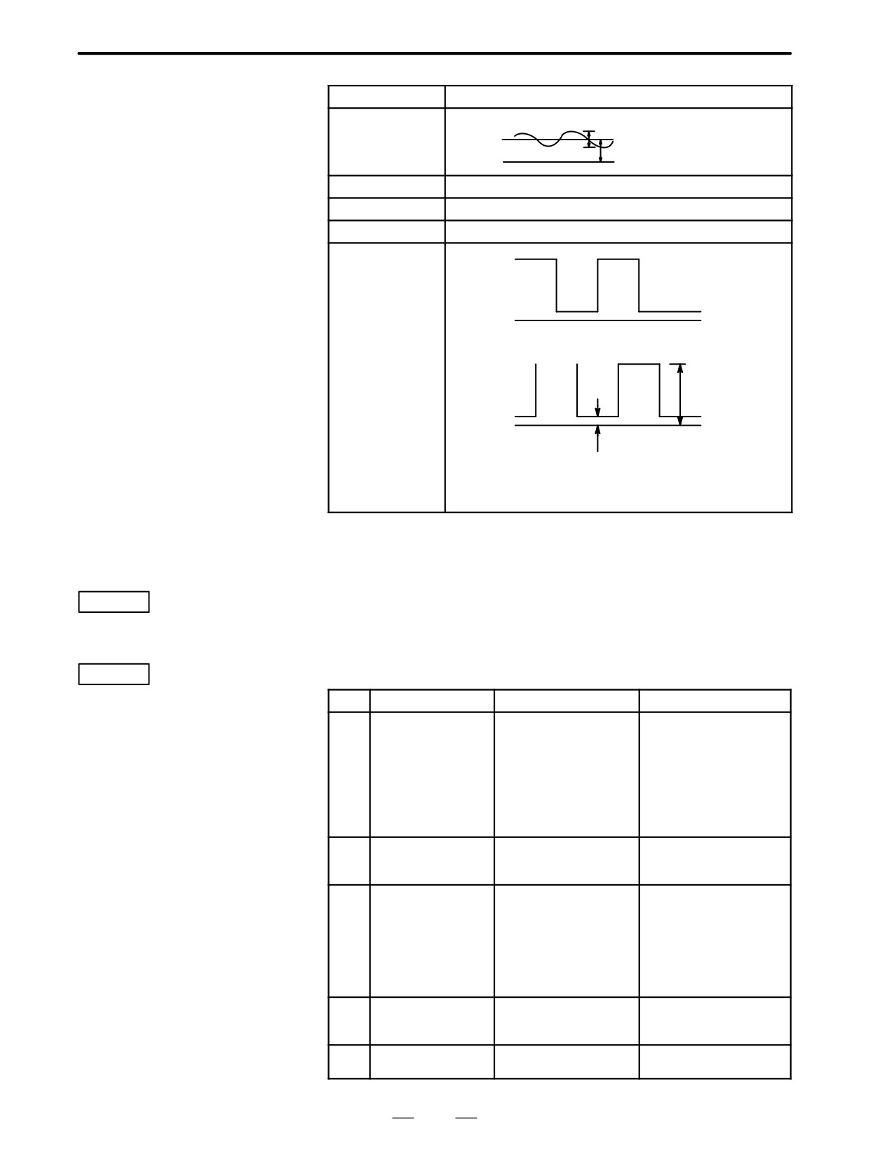
How to check the speed feedback signal
Observe the speed feedback signal with an osciloscope
after turning on power and setting the rotation command off
(motor stopped and drive power set off).
Observe the test points indicated below, while turning the
motor slowly by hand.
404
B-62445E/03
9. TROUBLESHOOTING (SERIAL INTEFACE SPINDLE)
Test point
Normal wave form
PA-0V
Vp-p=0.36 - 0.5V
About 2.5V
0V
PB-0V
Same as above
RA-0V
DC2.5V±0.2V
RB-0V
Same as above
PAA-0V
ON OFF
PAP
PBA-0V
(CW rotation)
0V
PBP
ON OFF
4.5V
0V
0.4V
Check that the ON/OFF duty cycle is 50%. (The PAP
and PBP signals are inverted in CCW direction.)
AL-03
Blown fuse in DC
This alarm indicates that the fuse (F4) in the DC link section is blown.
In this case, the transistor module may have failed.
link section
AL-04
Input fuse blown
Input power open
Item
Cause of trouble
Check procedure
Remedy
phase
High impedance on
Alarm No. 04 is on only at
Change power supply to
AC power supply
time of deceleration from
one with low impedance.
side.
high speed operation.
There may be loose con-
Example:
Alarm No. 04 can be on
nection of input power
1
Two transformers
when F1 to F3 are not
cable
are connected in
blown.
Example:
series, or variable
Open phase due to
autotransformer is
screws not tightened
connected.
firmly
Defective transistor
Replace transistor module
2
module
and fuse.
Defective diode mod-
Disconnect diode mod-
Replace defective part.
ule or thyristor mod-
ules DM1 to DM3 and thy-
Replace blown fuse.
ule
ristor modules SM1 to
SM3, then check A-K
3
connection with multime-
ter.
(Defective modules
are usually short-cir-
cuited.)
Defective surge ab-
Check surge absorbers
Replace defective part.
4
sorber or capacitor
Z1 to Z3 and capacitors
Replace blown fuse.
C4 to C6.
When input fuse is
Check if Item 1 is applica-
When Item 1 is not applica-
5
not blown
ble.
ble, replace PCB.
405
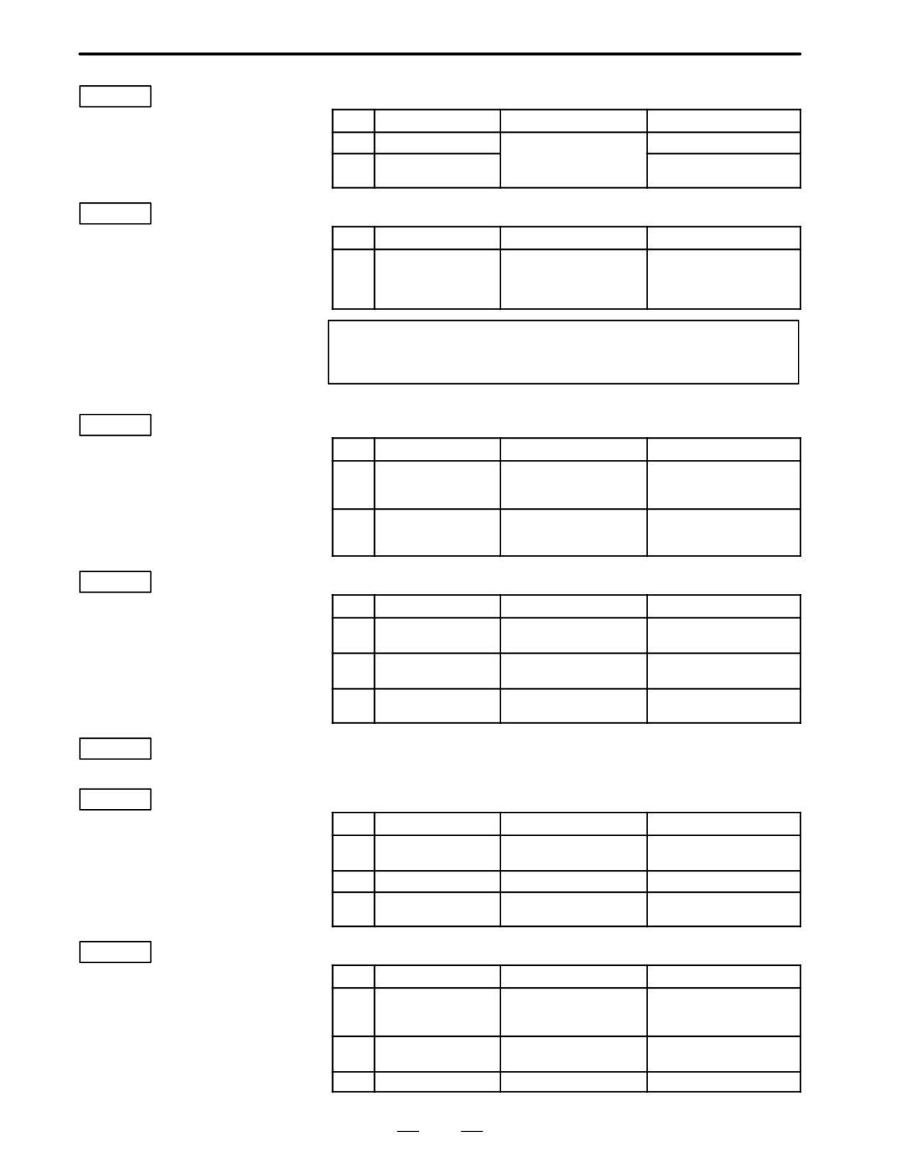
9. TROUBLESHOOTING (SERIAL INTERFACE SPINDLE)
B-62445E/03
AL-05
Control power
supply fuse blown
Item
Cause of trouble
Check procedure
Remedy
1
Defective PCB
Replace PCB.
Check AC input voltage
Abnormal power sup-
See (5) above.
2
ply voltage
AL-07
Excessive speed
(Detection by
Item
Cause of trouble
Check procedure
Remedy
digital value)
Incorrect setting of
Check if number of speed
Set correct value in
parameter for number
feedback pulses matches
parameter.
1
of speed feedback
parameter setting.
pulses (No. 6511)
Note
See Chapter 6.
AL-08
High input voltage
Item
Cause of trouble
Check procedure
Remedy
AC power supply volt-
Check power supply
1
age 10% higher than
voltage.
rated voltage.
Incorrect setting of
Check power supply
Change setting from 200V
2
toggle switch for volt-
voltage.
to 230V.
age switching.
AL-09
Heat sink is
overheated
Item
Cause of trouble
Check procedure
Remedy
Cooling fan is defec-
Check if fan is rotating.
Replace fan.
1
tive.
Overload operation.
Check load by using a
Re-examine the cutting
2
load meter.
condition.
Dusty and dirty.
Clean using compressed
3
air or vacuum cleaner.
This alarm indicates abnormally low AC power voltage (-15% or less).
AL-10
Input power
This alarm may be generated even during momentary power failures.
voltage drops
AL-11
Overvoltage of DC
link circuit
Item
Cause of trouble
Check procedure
Remedy
(Regenerative
High power imped-
Examine AC power specifi-
1
ance.
cation.
circuit is
faulty…Regenerati
2
PCB is defective.
Replace PCB.
on failure)
Defective transistor
Replace transistor mod-
3
module (TM1).
ule.
AL-12
Overcurrent flows
to DC link circuit
Item
Cause of trouble
Check procedure
Remedy
Output terminals or
Check connections.
1
internal circuit of mo-
tor is shorted.
Transistor module is
Check the transistor
Replace transistor module.
2
defective.
module.
3
PCB is defective.
Replace PCB.
406
B-62445E/03
9. TROUBLESHOOTING (SERIAL INTEFACE SPINDLE)
Replace PCB .
AL-13
CPU internal data
memory alarm
AL-16
RAM abnormality
Item
Cause of trouble
Check procedure
Remedy
External data memory
Replace memory (RAM).
1
(RAM) defective
2
PCB defective
Replace PCB.
AL-18
Program ROM
sum check error
Item
Cause of trouble
Check procedure
Remedy
Program memory
Compare data displayed
Replace program memory
1
data (ROM) defective
when power is turned ON
(ROM).
with ROM labels.
AL-19
Excessive U
phase current
Item
Cause of trouble
Check procedure
Remedy
detection circuit
A/D converter defec-
Replace A/D converter.
1
offset
tive
U-phase current de-
After power is turned on,
Replace PCB.
tector circuit defective
check if offset voltage on
2
check terminal IU is be-
yond range of about
100
mV.
Loose contact of con-
Check connector connec-
Ensure that PCB and pow-
3
nectors between PCB
tion between PCB and
er circuit are securely con-
and power circuit
power circuit.
nected with each other.
AL-20
Excessive V
phase current
Item
Cause of trouble
Check procedure
Remedy
detection circuit
V-phase current de-
After power is turned on,
Replace PCB.
offset
tector circuit defective
check if offset voltage on
1
check terminal IV is be-
yond range of about
100
mV.
Loose contact of con-
Check connector connec-
Ensure that PCB and pow-
2
nectors between PCB
tion between PCB and
er circuit are securely con-
and power circuit
power circuit.
nected with each other.
AL-24
Serial transfer
data error
Item
Cause of trouble
Check procedure
Remedy
CNC power supply is
Check that CNC power is
Turn CNC power ON.
AL-25
Serial data
1
OFF
ON.
transfer stopped
Defective optical
Check that optical cable is
Connect securely.
cable for serial data
fitted securely to the con-
Replace optical cable.
transmission
nector. Check that the
Clean optical cable trans-
2
cable is not broken.
mission/reception sur-
Check that transmission/
faces.
reception surfaces of the
cable are clean.
Defective data trans-
Replace LSI.
mission/reception ele-
Replace PCB.
3
ments in LSI used in
serial data transmis-
sion
407
9. TROUBLESHOOTING (SERIAL INTERFACE SPINDLE)
B-62445E/03
AL-26
Disconnection of
speed detection
Item
Cause of trouble
Check procedure
Remedy
signal for Cs
Signal level of spindle
Check the signal, and if necessary adjust to the normal
motor for Cs
level using the variable resistor for signal level adjust-
contouring
1
contouring control is
ment in the preamp.
control
invalid.
Signal line of spindle
Check that signal cable is
Connect signal cable se-
motor for Cs contour
connected securely to
curely.
2
control is
connector.
Replace signal cable.
defective
Check that signal cable is
not broken.
Defective detector cir-
Replace detector circuit.
3
cuit for Cs contour
control
Incorrect parameter
Check that the parameter
Parameter CAXIS1 = 0
setting
setting does not indicate
No. 4001#5
4
that the Cs contour
control detector is used
when actually it is not.
AL-27
Position coder
signal
Item
Cause of trouble
Check procedure
Remedy
disconnection
Position coder signal
Check that signal cable is
Connect signal cable se-
line defective
connected securely to
curely.
1
connector.
Replace signal cable.
Check that signal cable is
not broken.
Incorrect parameter
Check that the parameter
Parameter MRDY2 = 0
setting
setting does not indicate
No. 4001#2
2
that the position coder
signal is used when actu-
ally it is not.
AL-28
Disconnection of
position detection
Item
Cause of trouble
Check procedure
Remedy
signal for Cs
Signal level of spindle
Check the signal level, and if necessary adjust to the
1
detector for Cs axis
normal level using the variable resistor for signal level
contouring
control is defective
adjustment in the preamp.
control
Signal line of spindle
Check that signal cable is
Connect signal cable se-
detector for Cs axis
connected securely to
curely.
2
control is defective
connector.
Replace signal cable.
Check that signal cable is
not broken.
Defective detector cir-
Replace detector circuit.
3
cuit for Cs axis
control
AL-29
Short-time
overload
Item
Cause of trouble
Check procedure
Remedy
Overloaded opera-
Use loadmeter to check
Re-examine cutting
tion (Overload)
that a load close to the
conditions and tools.
1
load resistance limit is not
imposed continuously for
30 seconds or more.
408
B-62445E/03
9. TROUBLESHOOTING (SERIAL INTEFACE SPINDLE)
AL-30
Input circuit
overcurrent
Item
Cause of trouble
Check procedure
Remedy
Defective of power
Check power transistor.
Replace power transistor.
1
transistor used for
power
Defective of power
Replace PCB.
2
regeneration circuit
AL-31
Speed detection
signal
Item
Cause of trouble
Check procedure
Remedy
disconnection
Motor constrained
Check that nothing is
Remove cause.
motor restraint
1
preventing the motor from
accelerating.
alarm
Defective motor
Check signal waveform.
Remove cause.
2
speed feedback
(Alarm No. 2)
signal
Defective motor
Check that cable is con-
Connect cable securely.
speed feedback
nected securely to con-
Replace cable.
3
signal cable
nector.
Check that cable is not
broken.
AL-32
Abnormality in
RAM internal to
Item
Cause of trouble
Check procedure
Remedy
LSI for serial data
Defective LSI used in
Replace LSI.
transfer
1
serial data transmis-
Replace PCB.
sion
AL-33
Insufficient DC
link section
Item
Cause of trouble
Check procedure
Remedy
charging
Defective relay used
Check relevant parts.
Replace amp.
in DC link rechar-
1
ging.Disconnection of
resistor used in limit-
ing re-charge current
AL-34
Parameter data
setting beyond
Item
Cause of trouble
Check procedure
Remedy
allowable range
Incorrect parameter
Check if specified param-
Specify value within allow-
1
setting
eter value is beyond al-
able range.
of values
lowable range of values.
AL-34
and
F-XXX
are alternately displayed in the spindle amplifier
indicator section if an AL-34 alarm is raised.
”XXX” indicates the data number internal to the spindle for a parameter
where a value beyond the allowable range is specified.
AL-35
Excessive gear
ratio data setting
Item
Cause of trouble
Check procedure
Remedy
Parameter data of
Check gear ratio and
Change to suitable values.
gear ratio and posi-
position gain data.
1
tion gain are too
large.
409
9. TROUBLESHOOTING (SERIAL INTERFACE SPINDLE)
B-62445E/03
AL-37
Speed detector
parameter setting
Item
Cause of trouble
Check procedure
Remedy
error
Incorrect setting of
Check if number of speed
Set correct value in
parameter for number
feedback pulses matches
parameter.
1
of speed feedback
parameter setting.
pulses (No. 6511)
AL-39
Alarm for
indicating failure
Item
Cause of trouble
Check procedure
Remedy
in detecting
Incorrect data ROM
Check data ROM type for
Install correct type of
type for Cs contouring
Cs contouring control
ROM.
1-rotation signal
1
control detector
detector circuit and
Perform setting correctly.
for Cs contouring
circuit, or incorrect
setting.
setting
control
Low level of Cs con-
Check feedback signal
Adjust feedback signal.
touring control feed-
level and also check if
Check shielding status.
2
back signal, or noise
feedback signal waveform
on same feedback
includes noise.
signal
AL-40
Alarm for
indicating
Item
Cause of trouble
Check procedure
Remedy
1-rotation signal
No occurrence of
Check 1-rotation signal
Make 1-rotation signal
1-rotation signal
among Cs contouring
offset adjustment.
for Cs contouring
among Cs contouring
control feedback signals.
Check cables.
control not
1
control feedback
signals, or 1-rotation
detected
signal offset adjust-
ment error
AL-41
Alarm for
indicating failure
Item
Cause of trouble
Check procedure
Remedy
in detecting
Incorrect setting of
Check number of position
Set correct value in param-
parameter for number
coder signal pulses and
eter.
position coder
1
of position coder sig-
parameter setting.
1-rotation signal
nal pulses (No.
4003#4,6,7).
Incorrect amplitude
Check feedback signal
Adjust feedback signal.
and offset of position
level and also check if
Check shielding status.
2
coder feedback sig-
feedback signal waveform
nal, or noise on same
includes noise.
feedback signal.
AL-47
Position coder
signal
Item
Cause of trouble
Check procedure
Remedy
abnormality
Incorrect setting of
Check number of position
Set correct value in param-
parameter for number
coder signal pulses and
eter.
1
of position coder sig-
parameter setting.
nal pulses
(No. 4003#4,6,7).
Incorrect amplitude
Check feedback signal
Adjust feedback signal.
and offset of position
level and also check if
Check shielding status.
2
coder feedback sig-
feedback signal waveform
nal, or noise on same
includes noise.
feedback signal.
410

10. TROUBLESHOOTING
B-62445E/03
(ANALOG INTERFACE SPINDLE)
TROUBLESHOOTING (ANALOG INTERFACE SPINDLE)
10
This chapter describes troubleshooting of the analog interface spindle.
10.1
AL-01 (MOTOR OVERHEAT) .
412
10.2
AL-02
(EXCESSIVE DEVIATION OF SPEED) .
413
10.3
AL-06,07 (OVER SPEED) .
414
10.4
AL-09
(UNIT OVERHEAT / 6S TO 26S ONLY) .
415
10.5
AL-10 (LOW INPUT VOLTAGE) .
416
10.6
AL-11 (DC LINK EXCESSIVE VOLTAGE) .
417
10.7
AL-12 (DC LINK EXCESSIVE CURRENT) .
418
10.8
ABNORMAL SOUND AND VIBRATION
DURING ROTATION .
419
10.9
NO ROTATION OR INCORRECT SPEED .
420
10.10CONFIRMATION OF TRANSISTOR
MODULE .
421
411
10. TROUBLESHOOTING
(ANALOG INTERFACE SPINDLE)
B-62445E/03
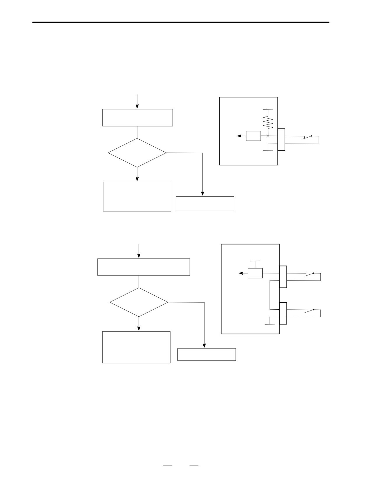
10.1
AL-01
(MOTOR OVERHEAT)
Model 6S to 22S (A20B-1003-0010)
(Start)
PCB
+24V
Measure voltage of *OH signal
at input side of receiver
R11
CN2
Inside motor
-3
TH
ALM
RV
24V
NO
-2
(contact open)
0V
?
YES
· Fan motor is not operating
· Overload
Reduce cutting condition
Receiver circuit is faulty
· Disconnection of signal line
Model 1S to 3S (A16B-1100-0200)
(Start)
PCB
+15V
CN2
Inside motor
Check continuity across pin 2 and 3 of
-3
TH
CN2 and pin 9 and 10 of CN4
ALM
RV
-2
NO
CN4
Contact open ?
Inside unit
-9
TH
YES
-10
0V
· Fan motor is not operating
· Overload
Reduce cutting condition
Receiver circuit is faulty
· Disconnection of signal line
412
10. TROUBLESHOOTING
B-62445E/03
(ANALOG INTERFACE SPINDLE)
10.2
AL-02
(EXCESSIVE
DEVIATION OF
SPEED)
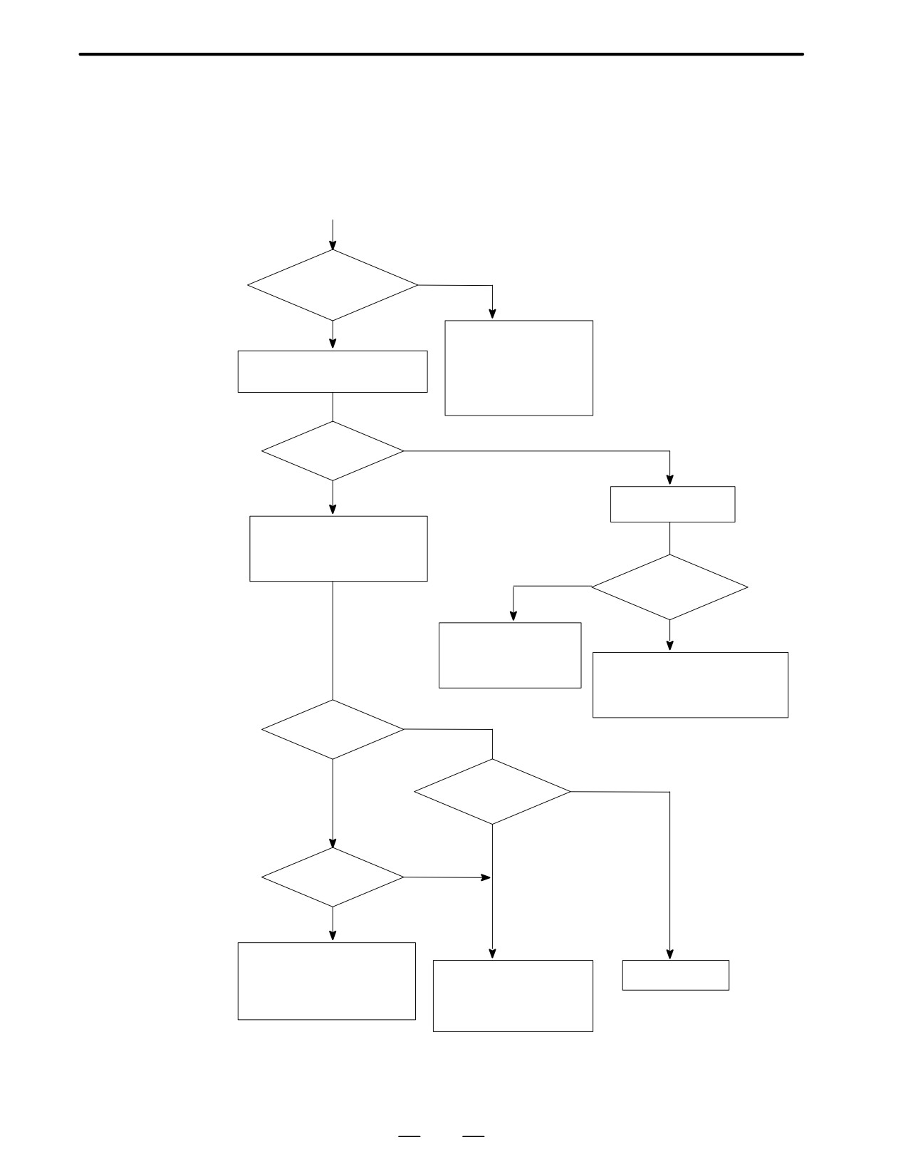
(Start)
Does it occur
YES
during deceleration?
NO
· Regenerative discharge
circuit is faulty
* Refer to 10.10
Apply a rotation command
· Regenerative transistor
”Confirmation of
and check whether motor rotates
module is faulty
Transistor Module”
· Load inertia is large
· PCB is faulty
NO (No rotation)
Does motor rotate?
YES
* Under AL-02
Command about
not generated
10 rpm speed.
Rotate the motor by hand
under emergency stop state
and check display of the speed
YES
Normal output at
terminal U, V, W?
NO
· Disconnection of
power line
· Motor is defective
·
PCB is faulty
· Machine load is large
·
Transistor module is faulty
(Disconnection across C and E)
·
Unit is faulty (Check Ch.VDC)
YES
Is the speed
displayed?
NO
YES (2.5V ±0.2V)
Check voltage of
RA and RB
(Normal)
NO
(2.5V ±0.2V)
Does PA and
YES
PB change?
NO
·
PCB is faulty
·
If current limitter is operating,
· Pulse generator is faulty
PCB is faulty
machine load is excessive
· Disconnection of feedback
(more than 4. 2V at IU)
cable
· Poor contact of connector
413
10. TROUBLESHOOTING
(ANALOG INTERFACE SPINDLE)
B-62445E/03
10.3
AL-06, 07
(OVER SPEED)
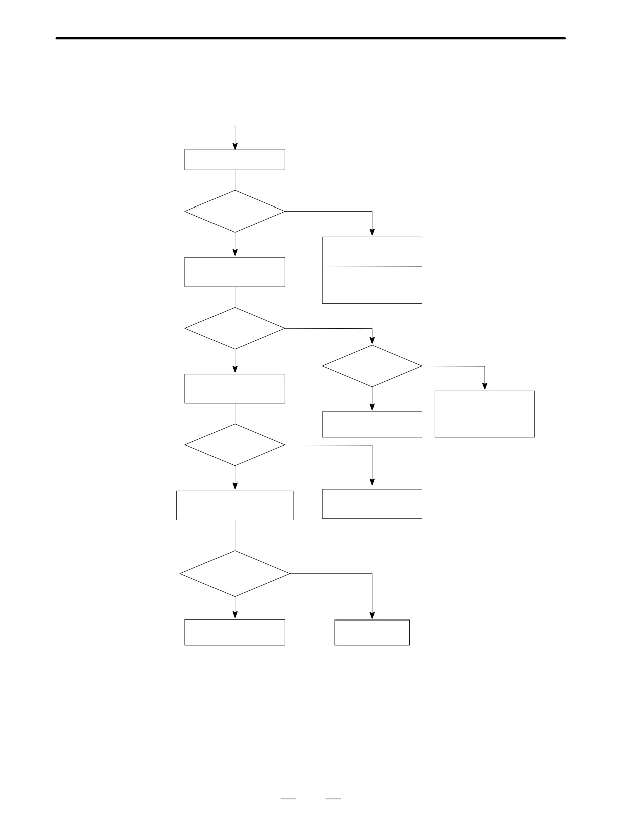
(Start)
Measure actual speed
NO (115% or less)
Does it exceed
rated speed?
YES
·
Check parameter F-05
*
Unused for 1S to 3S
Apply a speed command
and measure VCMD
·
Check specification of
ROM
·
PCB is faulty
YES
Does it exceed 10V?
NO
YES (10V or more)
DA2?
Measure ER under
emergency stop state
NO
· S analog voltage is in
(Normal)
error or adjustment is
required
PCB is faulty
· NC side PCB is faulty
NO
Nearly 0V?
YES
Rotate the motor by hand and
PCB is faulty
confirm PA, PB, and TSA
NO (No output at TSA)
Output at PA, PB,
and TSA
YES
Check parameters again
PCB is faulty
414
10. TROUBLESHOOTING
B-62445E/03
(ANALOG INTERFACE SPINDLE)
10.4
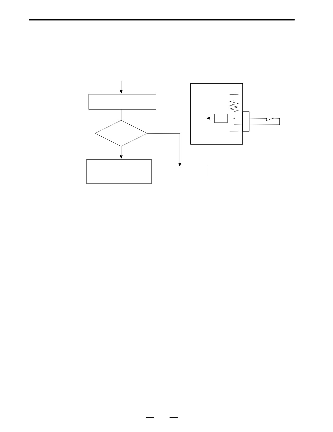
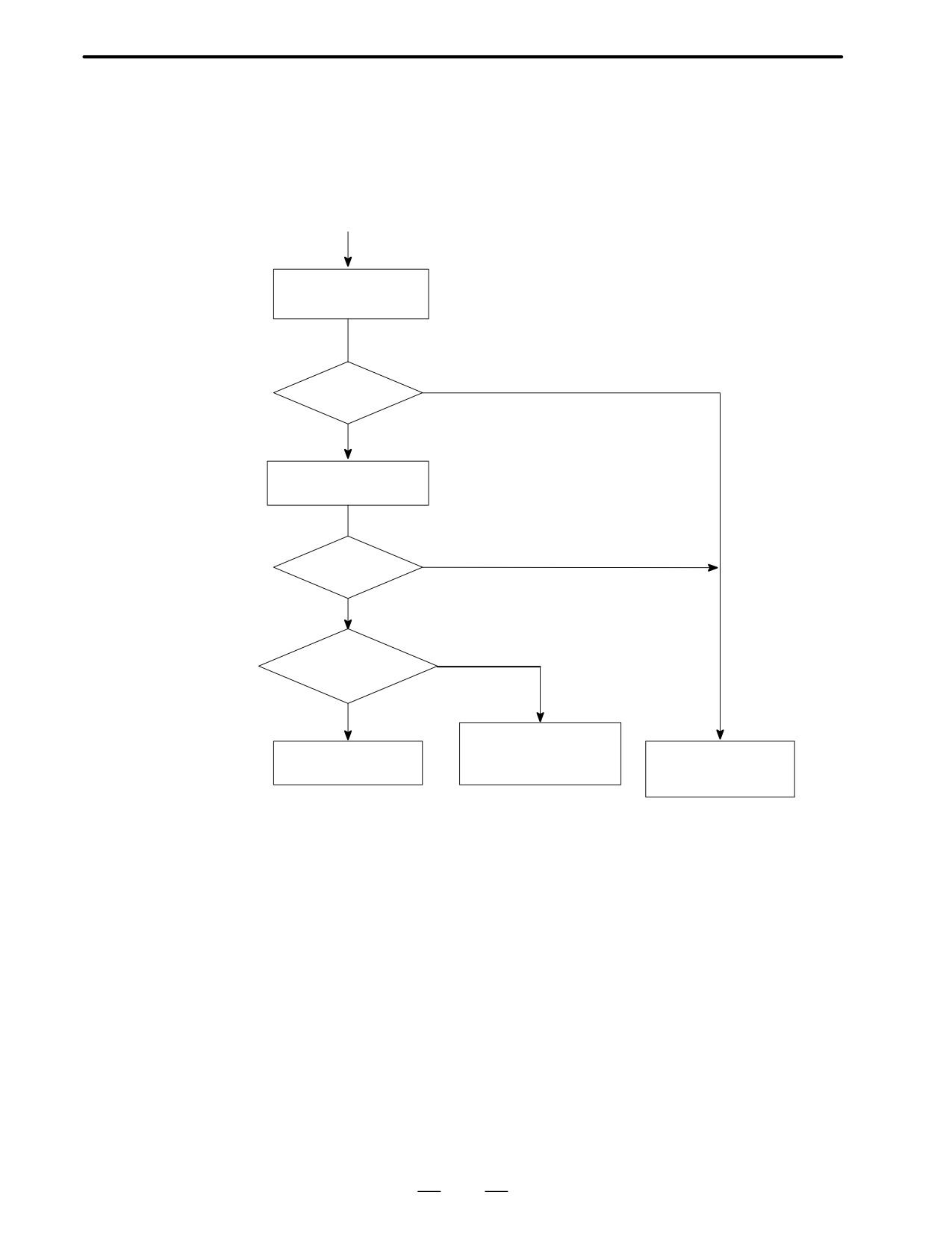
AL-09
(UNIT OVERHEAT /
6S TO 26S ONLY)
(Start)
PCB
+24V
Measure voltage of OVL signal
at input side of receiver
CN6
Inside unit
-6
TH
ALM
RV
NO
-7
24V (contact open?)
0V
YES
· Fan motor does not operate
· Overload
Receiver circuit is faulty
Check cutting conditions
· Disconnection of signal line
415
10. TROUBLESHOOTING
(ANALOG INTERFACE SPINDLE)
B-62445E/03
10.5
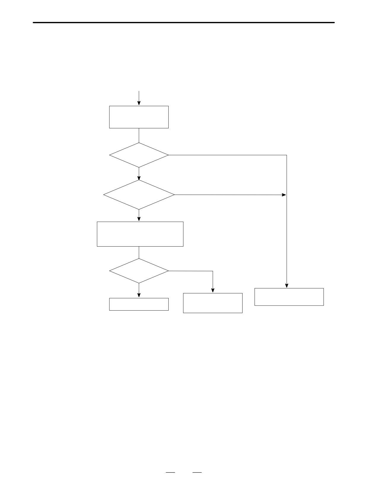
AL-10
(LOW INPUT
VOLTAGE)
(Start)
Measure voltage at check
SDC : 5V / 500V
terminal SDC on PCB
· Terminal DTDC for 1S to 3S
NO
1.5V or less?
YES
Check DC voltage across
* Confirm input voltage for 1S to 3S
4 and 5 of CN6
NO
Less than 150V?
YES
* No fuse for 1S to 3S
Does fuse FUR, FUS,
YES
FUT blown?
NO
· Serge absorber is faulty
· Fan motor is faulty
· Input voltage is low
· Instantaneous power
· Unit is faulty
· Unit is faulty
interruption
· PCB is faulty
416
10. TROUBLESHOOTING
B-62445E/03
(ANALOG INTERFACE SPINDLE)
10.6
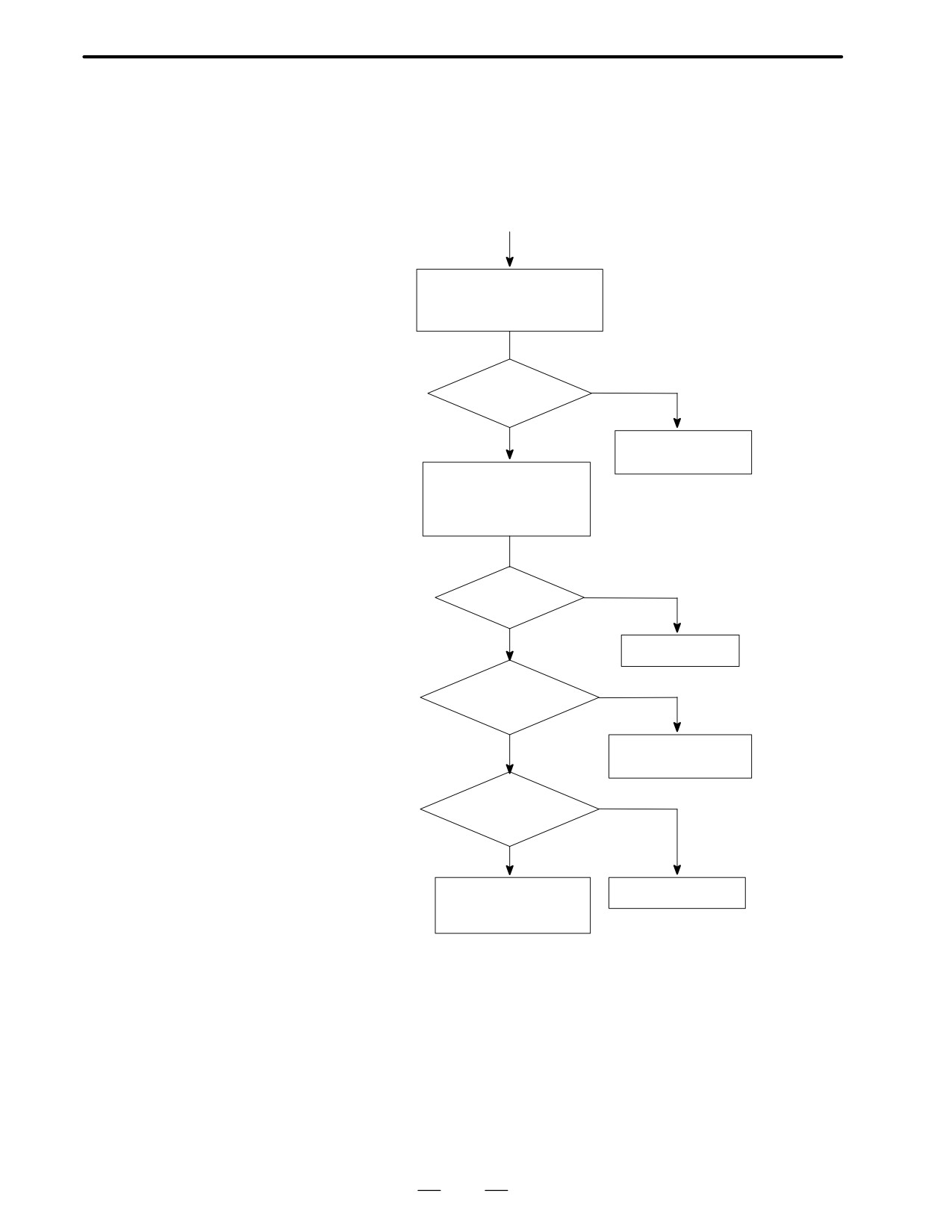
AL-11
(DC LINK EXCESSIVE
VOLTAGE)
(Start)
VDC : 5V/500V
Measure voltage at
test point VDC
YES
4.5V or more
NO
NO
Does it occur during
deceleration
YES
Measure resistance across C and E
* Registor for discharge circuit
of transistor module for generative
or transistor is disconnected for
discharge circuit
1S to 3S
YES
Shorted?
NO
· Confirm input voltage
Replace transistor
· Check noise of input signal
Input voltage is low
module and PCB
417
10. TROUBLESHOOTING
(ANALOG INTERFACE SPINDLE)
B-62445E/03
10.7
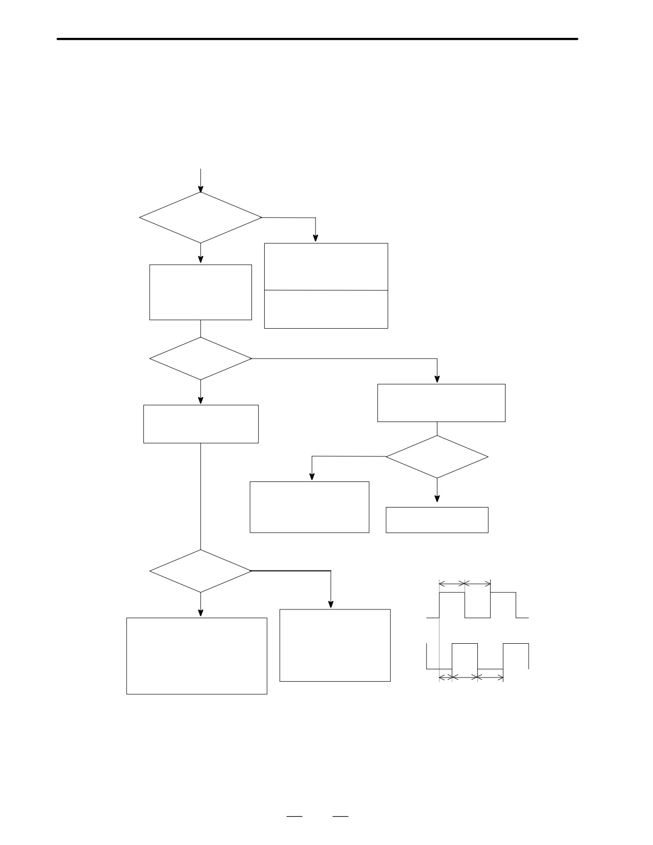
AL-12
(DC LINK EXCESSIVE
CURRENT)
(Start)
Remove the power line and
measure resistance across C
and E of transistor module
YES
Short-circuited
across C and E?
NO
Replace transistor
module and PCB
Turn on power with power
line removed.
Give a speed command of
serval tens rpm.
YES
AL-12?
NO
PCB is faulty
Is power line
YES
short-circuited
or grounded?
NO
· Power line is faulty
· Motor is faulty
YES
Does it occur during
deceleration?
NO
PCB is faulty (vibration)
Check input voltage
Current feedback signal
is abnormal
418
10. TROUBLESHOOTING
B-62445E/03
(ANALOG INTERFACE SPINDLE)
10.8
ABNORMAL SOUND
AND VIBRATION
DURING ROTATION
(Start)
YES
Does it occur during
deceleration
NO
Check regenerative discharge
* For 1S to 3S, disconnection of
circuit (pause of regeneration)
transistor of discharge circuit or
Check waveform
· Check transistor module
discharge resistor
with synchroscope
during rotation
· TSA
If load inertia is large,
· ER
decrease value of F-20
NO
Is abnormality
confirmed?
YES
* Take enough care
Remove connector CN2 during
* Do not execute frequently
rotation, and the machine may
Check relation between
move a little.
frequency of vibration and
speed by changing speeds
NO
Is abnormal
sound heard?
YES
Electric system is abnormal
· Check incorrect signal of
pulse generator
· PCB is faulty
Problem of machine
NO
Feedback signal of pulse generator
Is there any
1 : 1
relation?
+5V
YES
PAP
· Check incorrect signal
0V
· Check gear between spindle
of pulse generator
and spindle motor
· Failure of machine
+5V
· Observe frequency of vibration
· PCB is faulty
per motor rotation and check
· Check parameters F-21,
PBP
the mechanical element that has
22, 25, and 26
0V
the frequency
1/2
1 : 1
419
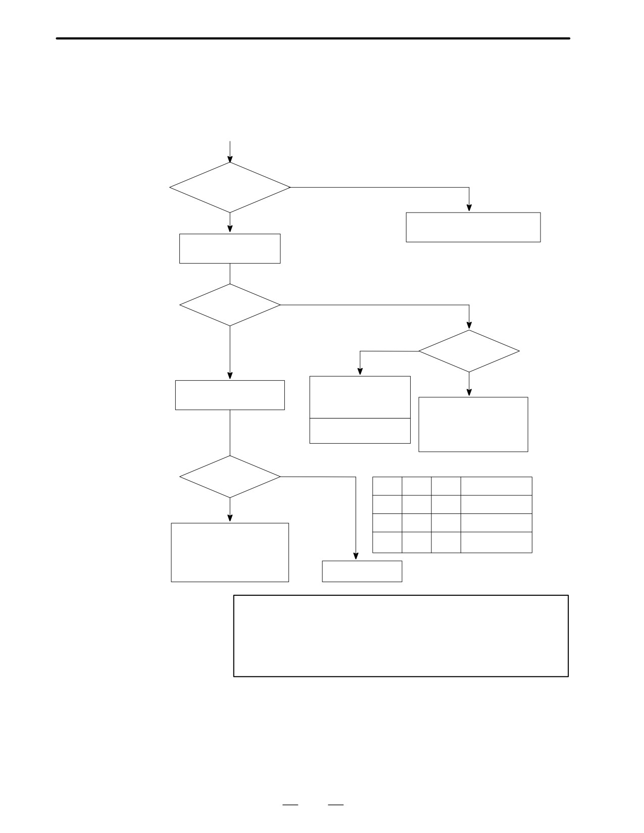
10. TROUBLESHOOTING
(ANALOG INTERFACE SPINDLE)
B-62445E/03
10.9
NO ROTATION OR
INCORRECT SPEED
(Start)
NO
Is power supplied to
PCB correctly?
YES
· Check input voltage
· Check power circuit within PCB
Give a rotation command
NO (0V or too low)
Is VCMD normal?
YES
YES
Is voltage at
DA2 normal?
NO
Check whether MCC is on.
· Check SFR, SRV,
Check voltage at VDC.
SRCM signals
· Check S analog voltage
· Check override circuit
· Check setting of spindle
speed
⋅PCB is faulty
· Check machine side
magnetics circuit
YES (2.6 to 3.2V)
Is voltage normal?
SFR
SRV
ORCM
Spindle rotation
NO
1
0
0
Forward
(0V)
0
1
0
Reverse
MCC is off
Check following signals :
-
-
1
Orientation
⋅*ESP signal
⋅MRDY signal
⋅Speed zero signal (SSTP)
PCB is faulty
Caution
1
Whille you are checking above items, if the system may
recover, the spindle may suddenly start its rotation.
Therefore, take enough care when you access the spindle
or its peripherals.
420
10. TROUBLESHOOTING
B-62445E/03
(ANALOG INTERFACE SPINDLE)
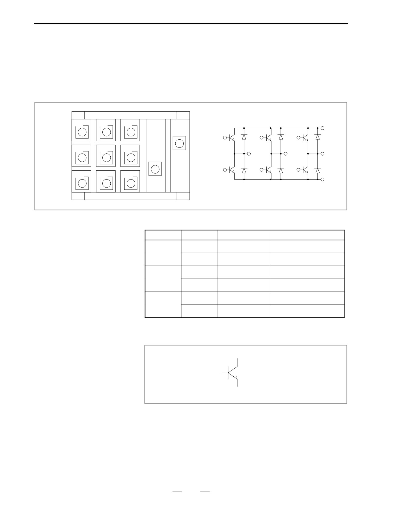
10.10
(1) Remove PCB-1 on the spindle amplifier.
CONFIRMATION OF
(2) Turn off power of main power supply of machine side and remove the
TRANSISTOR
motor power line.
MODULE
(3) Measure resistance across the following terminals of the transistor
module on the circuit board shown below with a tester.
B1
B3
B5
(+)
P
B1
B3
B5
B2
B4
B6
(-)
Uo
Vo
Wo
P (+)
N
B2
B4
B6
Uo
Vo
Wo
N
(-)
Judgement (Range of tester : x10 ohm)
Terminal
Tester
Normal
Abnormal
C : +
100 ohms
Short, infinity
C–E
C : -
Infinity
Short, 100 ohms
C : +
100 ohms
Short, infinity
C–B
C : -
Infinity
Short, 100 ohms
B : +
100 ohms
Short, infinity
B–E
B : -
100 ohms
Short, infinity
* When a transistor is defective, terminals across collector and
emitter, and across collector and base are short-circuited.
Collector (C)
Base (B)
Emittor (E)
421
APPENDIXES
B-62445E/03
APPENDIX
A. I/O UNIT MODEL A
I/O UNIT MODEL A
A
A.1SYSTEM CONFIGURATION .
426
A.2HARDWARE CONFIGURATION .
426
A.3LED INDICATION .
427
A.4FUSES .
428
A.5REMOVING A PRINTED CIRCUIT BOARD .
429
425