FANUC Series 16 / 160 / 18 / 180 – Model B. Maintenance Manual - page 4
B-62445E/03
1. DISPLAY AND OPERATION OF CRT/MDI
Inputting From FANUC Cassette
Data
Param-
Func-
prote
Function
eter
Mode
tion
Operation
ction
write=1
button
key
Inputting parameters
OFF
EDIT or
SYS-
[(OPRT)]→[ " ]→[READ]→[EXEC]
E.Stop
TEM
(PA-
RAM)
Inputting PMC pa-
OFF
E.Stop
SYS-
[
" ]→[I/O]→(CANNEL NO)<1> <INPUT>→(DEVICE
rameters
TEM
NAME) [FDCAS]→(KIND OF DATA) [PA-
(PMC)
RAM]→[READ]→(FILE NO) File no.<INPUT>→[EXEC]
Inputting offset val-
OFF
EDIT
OFF-
(Heading a file no.)→[(OPRT)]→[ " ]→[READ]→[EXEC]
ues
SET
Registering a pro-
OFF
EDIT
PROG
<N>→File no.→<INPUT>→[ " ]→[READ]→[EXEC]
gram
Inputting macro vari-
OFF
EDIT
PROG
<N>→File no.→<INPUT>→[ " ]→<O>→Program no. →
ables
[READ]→[EXEC]
MEMO
PROG
<START>
RY
Output to FANUC Cassette
Data
Param-
Func-
prote
Function
eter
Mode
tion
Operation
ction
write=1
button
key
SYS-
[(OPRT)]→[ " ]→[PUNCH]→[EXEC]
TEM
Output of parameter
EDIT
(PA-
RAM)
SYS-
[
" ]→[I/O]→(CANNEL NO)<1> <INPUT>→(DEVICE
Output of PMC pa-
EDIT
TEM
NAME) [FDCAS] →(KIND OF DATA) [PARAM] → [WRITE]
rameter
(PMC)
→ (FILE NO) <-> <1> <INPUT>→[EXEC]
OFF-
[(OPRT)]→[ " ]→[PUNCH]→[EXEC]
Output of offset
EDIT
SET
Output of all pro-
<O>→-9999→[ " ]→[PUNCH]→[EXEC]
EDIT
PROG
grams
Output of one pro-
<O>→Program no.→[ " ]→[PUNCH]→[EXEC]
EDIT
PROG
gram
Output of macro
OFF-
[ " ]→[MACRO]→[(OPRT)]→[ " ]→[PUNCH]→[EXEC]
EDIT
variables
SET
83
1. DISPLAY AND OPERATION OF CRT/MDI
B-62445E/03
Search
Data
Param-
Func-
prote
Function
eter
Mode
tion
Operation
ction
write=1
button
key
Searching a pro-
MEMO
<O>→Program no.→[O SRH]
gram number
RY
PROG
or EDIT
Searching a se-
MEMO
Program no. search→<N>→Sequence number→[NSRH]
PROG
quence number
RY
Searching an ad-
Data to be searched→[SRH↑] or[SRH↓] or <↑> <↓>
EDIT
PROG
dress word
(cursor key)
Searching an ad-
Address to be searched [SRH↑] or[SRH↓] or <↑> <↓>
EDIT
PROG
dress only
(Cursor key)
Searching an offset
OFF-
Offset no.→[NO.SRH]
-
number
SET
Searching a diag-
SYS-
Diagnostic number→[NO.SRH]
nostic number
TEM
-
(DGNO
S)
Searching a param-
SYS-
Parameter no.→[NO.SRH]
eter number
TEM
-
(PA-
RAM)
Edit
Data
Param-
Func-
prote
Function
eter
Mode
tion
Operation
ction
write=1
button
key
Display of memory
[LIB]
EDIT
PROG
capacity used
Deleting all pro-
OFF
<O>→-9999→<DELETE>
EDIT
PROG
grams
Deleting a program
OFF
EDIT
PROG
<O>→Program no.→<DELETE>
Deleting several
<N>→Sequence no.→<DELETE>
OFF
EDIT
PROG
blocks
(Deleted up to a block with a specified sequence no.)
Deleting a block
OFF
EDIT
PROG
<EOB>→<DELETE>
Deleting a word
OFF
EDIT
PROG
Searching a word to be deleted→<DELETE>
Changing a word
OFF
EDIT
PROG
Searching a word to be changed→New Data→<ALTER >
OFF
Searching a word immediately before a word to be
Inserting a word
EDIT
PROG
searched→New Data→<INSERT>
Collation
Data
Param-
Func-
prote
Function
eter
Mode
tion
Operation
ction
write=1
button
key
Collating memory
ON
EDIT
PROG
[(OPRT)]→[ " ]→[READ]→[EXEC]
84
B-62445E/03
1. DISPLAY AND OPERATION OF CRT/MDI
Playback
Data
Param-
Func-
prote
Function
eter
Mode
tion
Operation
ction
write=1
button
key
TEACH
Jog the machine→<X>,<Y> or <Z>→<INSERT>
-IN
→ NC data → <INSERT> → <EOB> → <INSERT>
Input of NC data
JOG/
PROG
HAN-
DLE
Clear
Data
Param-
Func-
prote-
Function
eter
Mode
tion
Operation
ction
write=1
key
key
Memory all clear
M/T
:
<RESET>AND<DELETE>
On 2path are controlled
At
On 2path are controlled
power
Path1
:
<CAN>AND<1>
ON
Path2
:
<CAN>AND<2>
Loader is controlled
:
<CAN>AND<5>
Parameter/offset
M/T
:
<RESET>
clear
On 2path are controlled
At
Path1
:
<RESET>AND<1>
f
Power
Path2
:
<RESET>AND<2>
ON
Loader is controlled
:
<RESET>AND<5> (Parameter
only)
Clearing a program
M/T
:
<DELETE>
At
On 2path are controlled
f
Power
Path1
:
<DELETE>AND<1>
ON
Path2
:
<DELETE>AND<2>
Loader is controlled
:
<RESET>AND<5>
Program under edi-
<PROG>AND<RESET>
tion at power
-
off(PS101)
PMC RAM (Note1)
At
Main CPU : <X>AND<0> (O)
Power
Loader is controlled
:
<X>AND<5>
ON
Additional SRAM
M/T
:
<O> (O) AND<DELETE>
At
area clear
On 2path are controlled
Power
Path1
:
<O> (O) AND<1>
ON
Path2
:
<O> (O) AND<2>
Note
If a PMC ladder program is stored in FROM, loading into
DRAM is not performed.
If a PMC ladder program is not stored in FROM, the ladder
area in DRAM is cleared.
85
1. DISPLAY AND OPERATION OF CRT/MDI
B-62445E/03
1.13
WARNING SCREEN
DISPLAYED WHEN
AN OPTION IS
CHANGED
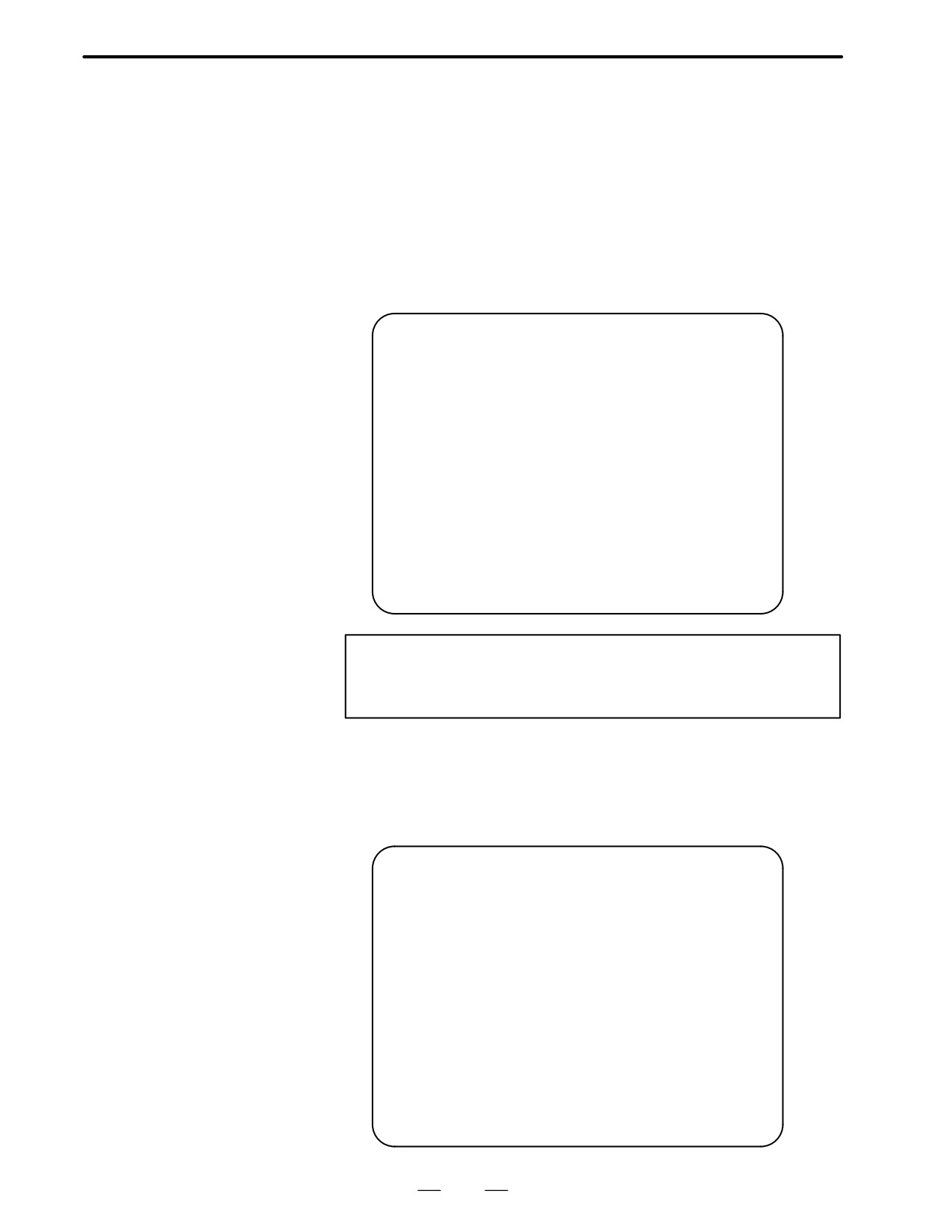
D Warning screen
This CNC displays a warning screen when the configuration of the
options using the SRAM area is changed. The data for the function
indicated on the screen is cleared the next time the system is turned
on.
WARNING
YOU SET THE PARAMETER NO.9921#2
THE FOLLOWING DATA WILL BE CLEARED.
* PART PROGRAM MEMORY
PLEASE PRESS <DELETE> OR <CAN> KEY.
<DELETE> : CLEAR ALL DATA
*1
<CAN>
: CANCEL
Note
This line varies with the parameter settings. Two or more
function names may be displayed.
D Allocation error screen
When an option which uses the SRAM area is added, the system software
may require more SRAM than is currently installed in the system. In this
case, an allocation error screen appears the first time the system is turned
on after the addition of the option, thus restoring the state existing before
the addition.
FILE ALLOCATION ERROR
S-RAM CAPACITY IS NOT SUFFICIENT.
ADDITIONAL S-RAM IS NECESSARY.
PLEASE PRESS <CAN> KEY :
RETURN TO THE STATE BEFORE
OPTION PARAMETER IS CHANGED.
*1
86
B-62445E/03
1. DISPLAY AND OPERATION OF CRT/MDI
Note
When the currently installed SRAM is not sufficient,
additional SRAM can be mounted. Newly installed SRAM
must be cleared before it can be used.
Operation:When turning on the power, hold down the
following keys:
<O>+<DELETE> for M/T series
<O>+<1> for two-path control (Main)
<O>+<2> for two-path control (Sub)
When installing additional SRAM, however, perform all
clear.
87

1. DISPLAY AND OPERATION OF CRT/MDI
B-62445E/03
System software can be replaced only with compatible system software.
1.14
Otherwise, the first time the CNC is turned on after the system software
WARNING SCREEN
is replaced, the following screen will be displayed and the system will not
DISPLAYED WHEN
be activated:
SYSTEM SOFTWARE
IS REPLACED
(SYSTEM LABEL
CHECK ERROR)
BOA1-01
SYSTEM LABEL CHECK ERROR:
CLEAR ALL SRAM MODULE
NOT READY
In this case, perform memory all clear (by holding down the
RESET
and
DELETE
MDI keys then turning on the power) or reinstall the original system
software.
88

2. HARDWARE
B-62445E/03
HARDWARE
2
This chapter describes structure of CNC control section, connection of
units and the functions of PCBs and modules mounted on PCBs.
2.1
STRUCTURE .
90
2.2
GENERAL OF HARDWARE .
91
2.3
TOTAL CONNECTION DIAGRAM .
92
2.4
NTER-MACHINE CONNECTION .
99
2.5
LED DISPLAY AND MODULE
CONFIGURATION OF PCB .
126
2.6
LIST THE OF PCBS AND UNITS. .
161
2.7
HOW TO REPLACE THE MODULES .
172
2.8
HOW TO REPLACE THE BATTERIES .
173
2.9
HOW TO REPLACE THE MOTORS .
175
2.10 FUSE REPLACEMENT IN POWER
SUPPLY UNIT .
176
2.11 MAINTENANCE OF HEAT PIPE TYPE HEAT
EXCHANGER .
177
2.12 HOW TO REPLACE THE COLOR LIQUID
CRYSTAL DISPLAY .
180
2.13 REPLACING THE LCD FUSE .
181
2.14 REPLACING THE LCD BACKLIGHT .
182
89
2. HARDWARE
B-62445E/03
2.1
STRUCTURE
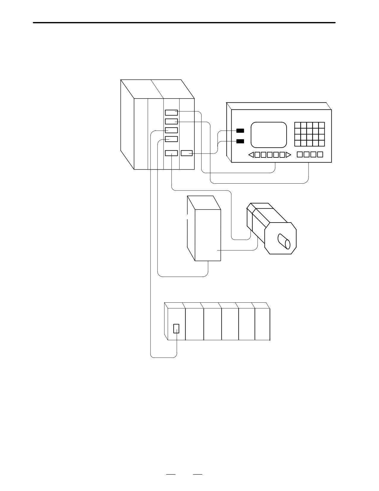
Control unit (4 slots)
CRT/MDI unit
OP2
OP1
MAIN
PSU
Series 16
ON
01234N1234
X 123.456
OFF
Z 456.789
SERVOMOTOR
SERVO AMP
C series
SERVO
AMP
I/O Unit MODEL - A
I/O LINK
AIF01A
↑
↓
Machine side operator’s panel magnetics circuit
90
2. HARDWARE
B-62445E/03
2.2
GENERAL OF
HARDWARE
2.2.1
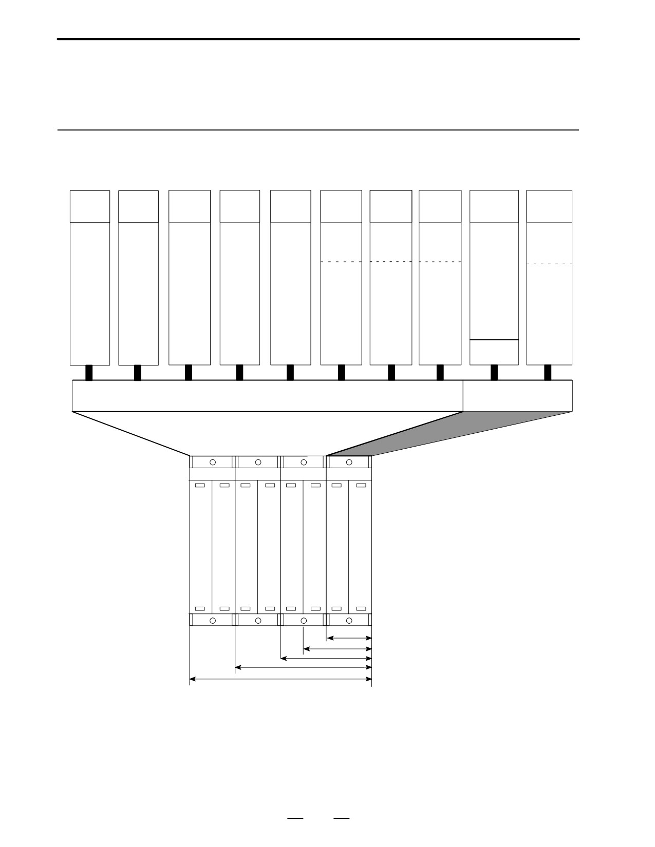
Series 16
Back
Loader
RISC
MCC
Option 3
Option 2
Option 1
Main CPU
Power
ground
I/O card
board
drawing
Board
control
board
board
board
board
supply unit
board
board
SUB CPU
Graphic con-
CNC CPU
RISC
Back
MCC
Loader
DI/DO
CAP CPU
trol
4-axis
On/Off
CPU
graund
function
control
40/ 40
(CAP II)
(CAP-II)
control
control
drawing
function
80/ 56
Spindle(x2)
function
104/ 72
PMC CPU
4-axis
Communica-
CRT/MDI
156/120
Power
tion function
PMC-RBS
(PMC-RC3)
control
supply unit
(Remote
I/O LINK
Spindle (x2)
AI/BI
buffer, DNC1,
MPG(x3)
I/O LINK
High speed
DI
DNC2)
RS-232-C
(x2)
Analog I/O
Graphic
control
funtion
OPTION
BASIC SYSTEM
ÈÈÈÈÈÈÈÈÈÈÈÈÈÈÈÈÈÈÈÈÈÈÈÈÈ
ÈÈÈÈÈÈÈÈÈÈÈÈÈÈÈÈÈÈÈÈ
ÈÈÈÈÈÈÈÈÈÈÈÈÈÈÈ
MAIN
CPU
Power
supply
2 slots
3 slots
4 slots
6 slots
8 slots
91

2. HARDWARE
B-62445E/03
2.3
TOTAL CONNECTION
DIAGRAM
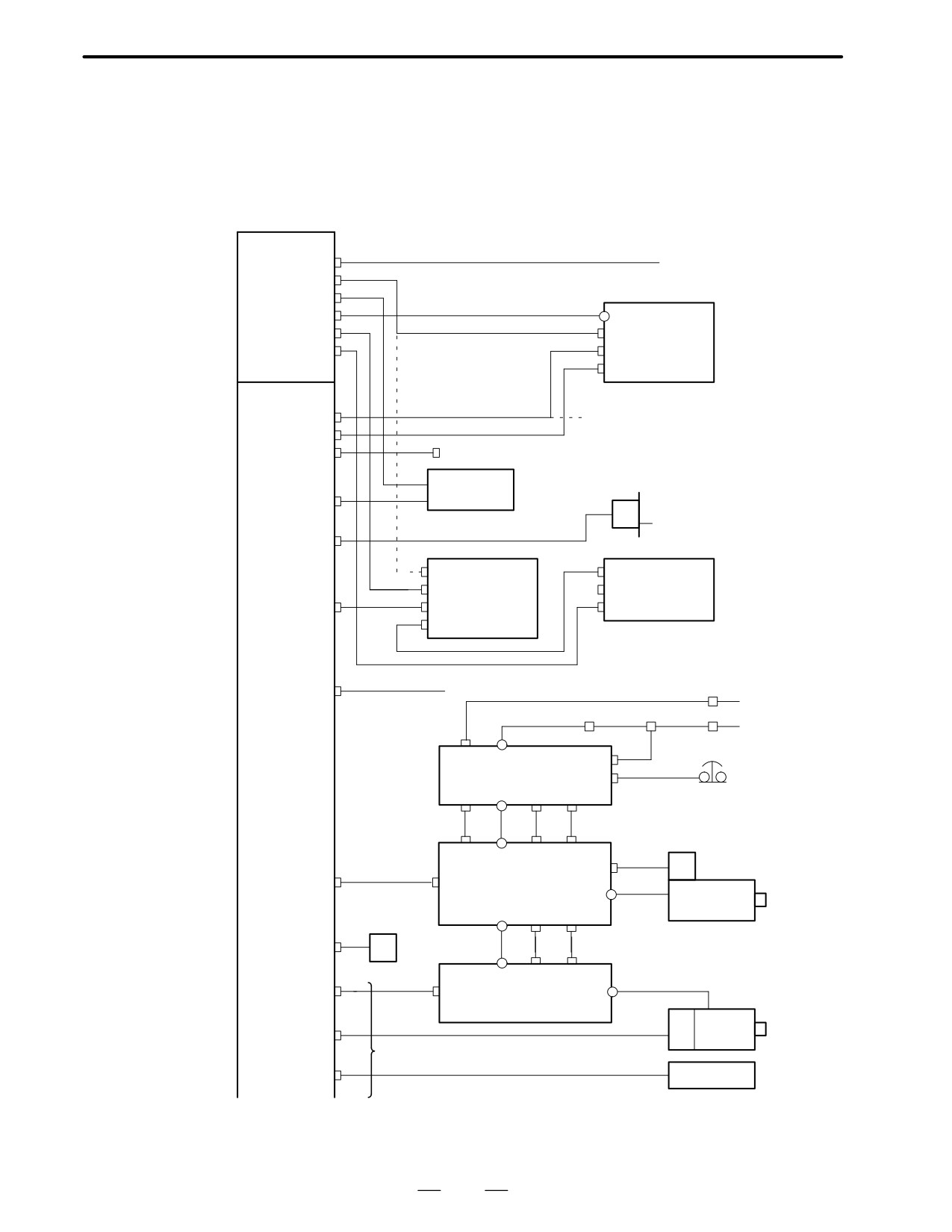
92
2. HARDWARE
B-62445E/03
2.3.1
16-TB/MB, 160-TB/MB
(MAIN-A SPEC.)
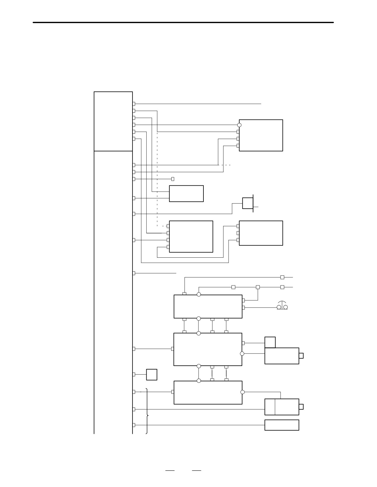
Power unit
AC-IN (CP1)
AC200XAC240V
AC-OUT (CP2)
For color CRT, PDP
(CP3)
AC200V
ON/OFF (CP4)
ON/OFF
+24V (CP5)
CN2
CRT/MDI
For monochro. CRT, LCD
CN1
+24E (CP6)
unit
DC24V
CK1
Main CPU
CRT (JA1)
From
MDI (JA2)
Option board 1 for CAP II
R232-1(JD5A)
MMC board for MMC
Punch panel
Tape reader
R232-2(JD5B)
MPG
3
MPG(JA3)
CPD1
Operators
JD1B
CPD1
panel in-
JD1A
I/O
JD1B
terface
CP32
Unit-A
IOLINK(JD1A)
JA1A
(Option 3
for PMC-RC)
A-OUT1(JA8A)
Analog voltage output
Braker
AC200V
AC reactor
MCC
Braker
AC200V
CX1A
TB2
CX3
Control motor amp.
PSM
CX4
α series
ÅÅ
CX1B TB1
CX2B JX1B
Emergency stop
CX1A TB1
CX2A JX1A
JY2
PC
SPDL-1(JA7A)
JA7B
SPM
Absolute
TB2
Spindle
PC battery
motor
TB1
CX2B JX1B
APCBAT(JA4A)
6V
TB1
CX2A JX1A
AMP1(JV1)
JA1B
SVM
TB2
(TYPE-A I/F)
Servo
PC
ENC1(JF1)
motor
1st axis or 1st axis in 1st path
SCALE1(JF21)
Linear scale
93
2. HARDWARE
B-62445E/03
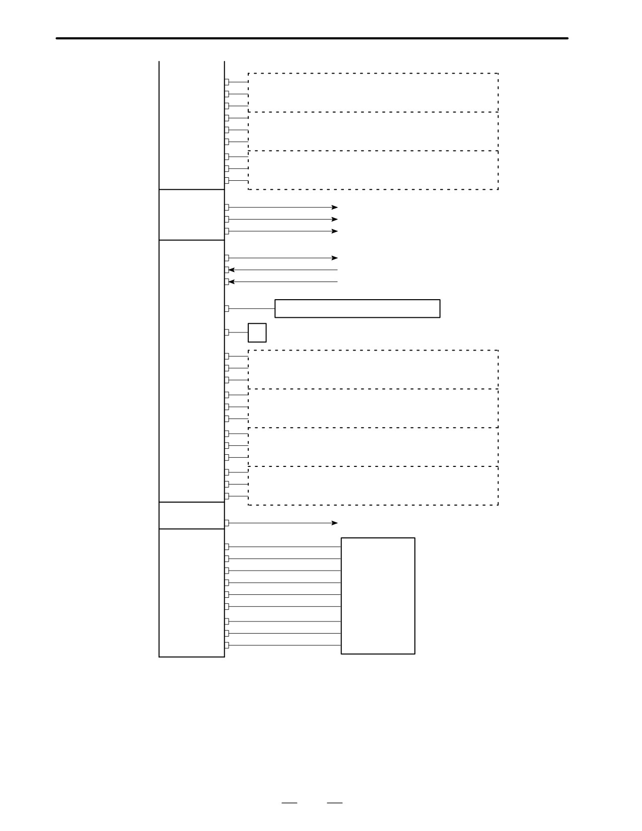
(Main CPU)
AMP2(JV2)
2nd axis servo amp/Serial PC/ Linear scale
ENC2(JF2)
or
2nd axis servo amp /Serial PC/ Linear scale in 1st path
SCALE2(JF22)
AMP3(JV3)
3rd axis servo amp/Serial PC/ Linear scale
ENC3(JF3)
or
SCALE3(JF23)
3rd axis servo amp /Serial PC/ Linear scale in 1st path
AMP4(JV4)
4th axis servo amp/Serial PC/ Linear scale
ENC4(JF4)
or
SCALE4(JF24)
4th axis servo amp /Serial PC/ Linear scale in 1st path
Option 1 board
CRT(JA1)
To CRT (with CAP II)
R422-1(JD6A)
Remote buffer /DNC 1
R232-3(JD5C)
Remote buffer
Option 2 board
A-OUT2(JA8B)
Analog voltage output
AIN(JA6)
Analog I/O
HDI(JA5)
High speed DI
SPDL-2(JA7B)
Control motor amp α series SPM
APCBAT(JA4B)
6V
Absolute pulse coder battery
AMP5(JV5)
5th axis servo amp/Serial PC/ Linear scale
ENC5(JF5)
or
SCALE5(JF25)
1st axis servo amp /Serial PC/ Linear scale in 2nd path
AMP6(JV6)
6th axis servo amp/Serial PC/ Linear scale
ENC6(JF6)
or
SCALE6(JF26)
2nd axis servo amp /Serial PC/ Linear scale in 2nd path
AMP7(JV7)
7th axis servo amp/Serial PC/ Linear scale
ENC7(JF7)
or
SCALE7(JF27)
3rd axis servo amp /Serial PC/ Linear scale in 2nd path
AMP8(JV8)
8th axis servo amp/Serial PC/ Linear scale
ENC8(JF8)
or
SCALE8(JF28)
4th axis servo amp /Serial PC/ Linear scale in 2nd path
Option 3 board
To I/O unit, Operator‘s panel
IOLINK(JD1A)
interface unit, etc. (for PMC-RC)
I/O card
DO-1(C54)
DO-2(C55)
DO-3(C56)
Operator‘s panel
DI-1(C50)
Magnetics cabinet
DI-2(C51)
DI-3(C52)
DI-4(C53)
DI-5(C56)
DI-6(C57)
94
2. HARDWARE
B-62445E/03
2.3.2
16-TB/MB, 160-TB/MB,
18-TB/MB, 180-TB/MB
(MAIN-B SPEC.)
Power unit
AC-IN (CP1)
AC200XAC240V
AC-OUT (CP2)
For color CRT, PDP
(CP3)
AC200V
ON/OFF (CP4)
ON/OFF
+24V (CP5)
CN2
CRT/MDI
For monochro. CRT, LCD
CN1
+24E (CP6)
unit
DC24V
CK1
Main CPU
CRT (JA1)
From
MDI (JA2)
Option board 1 for CAP II
R232-1(JD5A)
MMC board for MMC
Punch panel
Tape reader
R232-2(JD5B)
MPG
3
MPG(JA3)
CPD1
Operators
JD1B
CPD1
panel in-
JD1A
I/O
JD1B
terface
CP32
Unit-A
IOLINK(JD1A)
JA1A
(Option 3
for PMC-RC)
A-OUT1(JA8A)
Analog voltage output
Braker
AC200V
AC reactor
MCC
Braker
AC200V
CX1A
TB2
CX3
Control motor amp.
PSM
CX4
α series
ÅÅ
CX1B TB1
CX2B JX1B
Emergency stop
CX1A TB1
CX2A JX1A
JY2
PC
SPDL-1(JA7A)
JA7B
SPM
Absolute
TB2
Spindle
PC battery
motor
TB1
CX2B JX1B
APCBAT(JA4A)
6V
TB1
CX2A JX1A
AMP1(JV1)
JA1B
SVM
TB2
(TYPE-A I/F)
Servo
PC
ENC1(JF1)
motor
1st axis or 1st axis in 1st path
SCALE1(JF21)
Linear scale
95
2. HARDWARE
B-62445E/03
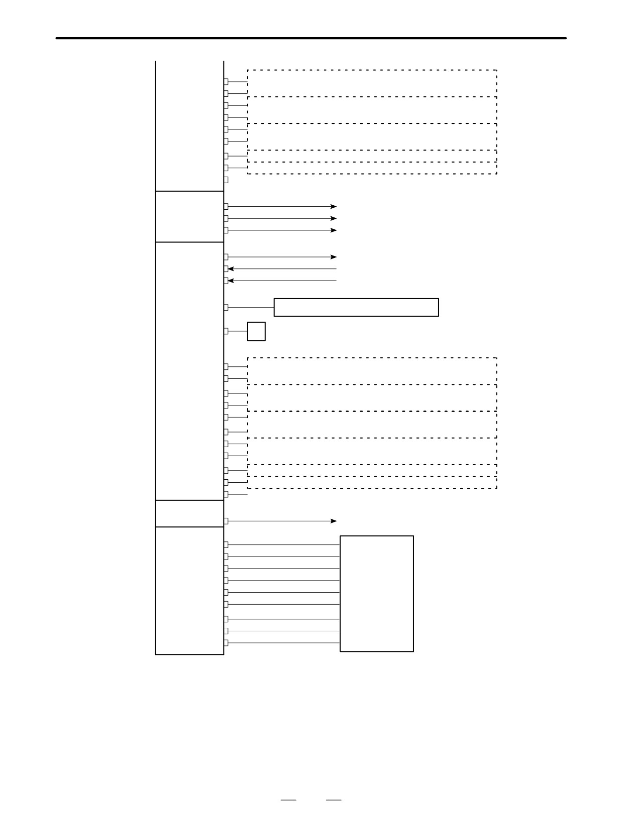
(Main CPU)
SERV02(JS2A)
2nd axis servo amp/Linear scale or
2nd axis servo amp/Linear scale in 1st path
SCALE2(JF22)
SERV03(JS3A)
3nd axis servo amp/Linear scale or
3nd axis servo amp/Linear scale in 1st path
SCALE3(JF23)
SERV04(JS4A)
4th axis servo amp/Linear scale or
4th axis servo amp/Linear scale in 1st path
SCALE4(JF24)
SERV05(JS5A)
5th axis servo amp or 5th axis servo amp in 1st path
SERV06(JS6A)
6th axis servo amp or 5th axis servo amp in 1st path
SV-CHK(JA26)
Connector for 5th and 6th servo check
Option 1 board
CRT(JA1)
To CRT (with CAP II)
R422-1(JD6A)
Remote buffer /DNC 1
R232-3(JD5C)
Remote buffer
Option 2 board
Analog voltage output
A-OUT2(JA8B)
Analog I/O
AIN(JA6)
High speed DI
HDI(JA5)
SPDL-2(JA7B)
Control motor amp α series SPM
APCBAT(JA4A)
6V
Absolute pulse coder battery
AMP1(JS1A-2)
7th axis servo amp/Linear scale or
SCALE1(JF21-2)
1st axis servo amp/Linear scale in 2nd path
AMP2(JS2A-2)
8th axis servo amp/Linear scale or
SCALE2(JF22-2)
2st axis servo amp/Linear scale in 2nd path
AMP3(JS3A-2)
3rd axis servo amp/Linear scale in 2nd path
SCALE3(JF23-2)
AMP4(JS4A-2)
4th axis servo amp/Linear scale in 2nd path
SCALE4(JF24-2)
AMP5(JS5A-2)
5th axis servo amp in 2nd path
AMP6(JS6A-2)
6th axis servo amp in 2nd path
SV-CHK(JA26)
Connector for 5th and 6th-axis servo check in 2nd path
Option 3 board
To I/O unit, Operator‘s panel
IOLINK (JD1A)
interface unit, etc. (for PMC-RC)
I/O card
DO-1(C54)
DO-2(C55)
DO-3(C56)
DI-1(C50)
Operator‘s panel
DI-2(C51)
Magnetics cabinet
DI-3(C52)
DI-4(C53)
DI-5(C56)
DI-6(C57)
96
2. HARDWARE
B-62445E/03
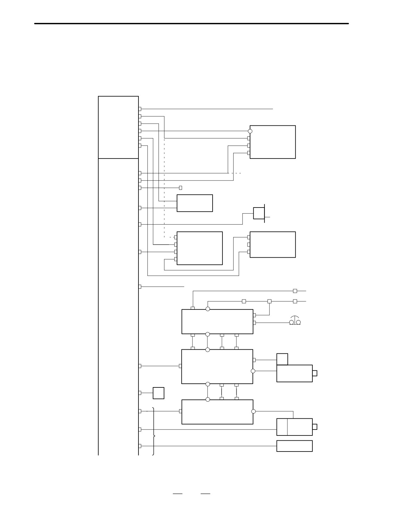
2.3.3
18-TB/MB
Power unit
AC-IN (CP1)
AC200XAC240V
AC-OUT (CP2)
For color CRT, PDP
(CP3)
AC200V
ON/OFF (CP4)
ON/OFF
+24V (CP5)
CN2
CRT/MDI
For monochro. CRT, LCD
CN1
+24E (CP6)
unit
DC24V
CK1
Main CPU
CRT (JA1)
From
MDI (JA2)
Option board 1 for CAP II
R232-1(JD5A)
MMC board for MMC
Punch panel
Tape reader
R232-2(JD5B)
MPG
3
MPG(JA3)
CPD1
Operators
JD1B
CPD1
panel in-
JD1A
I/O
JD1B
terface
CP32
Unit-A
IOLINK(JD1A)
JA1A
(Option 3
for PMC-RC)
A-OUT1(JA8A)
Analog voltage output
Braker
AC200V
AC reactor
MCC
Braker
AC200V
CX1A
TB2
CX3
Control motor amp.
PSM
CX4
α series
ÅÅ
CX1B TB1
CX2B JX1B
Emergency stop
CX1A TB1
CX2A JX1A
JY2
PC
SPDL-1(JA7A)
JA7B
SPM
Absolute
TB2
Spindle
PC battery
motor
TB1
CX2B JX1B
APCBAT(JA4A)
6V
TB1
CX2A JX1A
AMP1(JV1)
JA1B
SVM
TB2
(TYPE-A I/F)
Servo
PC
ENC1(JF1)
motor
1st axis or 1st axis in 1st path
SCALE1(JF21)
Linear scale
97
2. HARDWARE
B-62445E/03
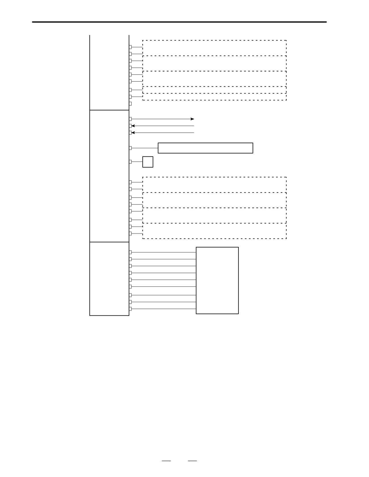
(Main CPU)
SERV02(JS2A)
2nd axis servo amp/Linear scale or
2nd axis servo amp/Linear scale in 1st path
SCALE2(JF22)
SERV03(JS3A)
3nd axis servo amp/Linear scale or
3nd axis servo amp/Linear scale in 1st path
SCALE3(JF23)
SERV04(JS4A)
4th axis servo amp/Linear scale or
4th axis servo amp/Linear scale in 1st path
SCALE4(JF24)
SERV05(JS5A)
5th axis servo amp or 5th axis servo amp in 1st path
SERV06(JS6A)
6th axis servo amp or 5th axis servo amp in 1st path
SV-CHK(JA26)
Connector for 5th axis and 6th servo check
Option 2 board
Analog voltage output
A-OUT2(JA8B)
Analog I/O
AIN(JA6)
High speed DI
HDI(JA5)
SPDL-2(JA7B)
Control motor amp α series SPM
APCBAT(JA4A)
6V
Absolute pulse coder battery
AMP1(JS1A-2)
1st axis servo amp/ Linear scale in 2nd path
SCALE1(JF21-2)
AMP2(JS2A-2)
2nd axis servo amp/ Linear scale in 2nd path
SCALE2(JF22-2)
AMP3(JS3A-2)
3rd axis servo amp/Linear scale in 2nd path
SCALE3(JF23-2)
AMP4(JS4A-2)
4th axis servo amp/Linear scale in 2nd path
SCALE4(JF24-2)
I/O card
DO-1(C54)
DO-2(C55)
DO-3(C56)
DI-1(C50)
Operator‘s panel
DI-2(C51)
Magnetics cabinet
DI-3(C52)
DI-4(C53)
DI-5(C56)
DI-6(C57)
98
2. HARDWARE
B-62445E/03
2.4
INTER-MACHINE
CONNECTION
2.4.1
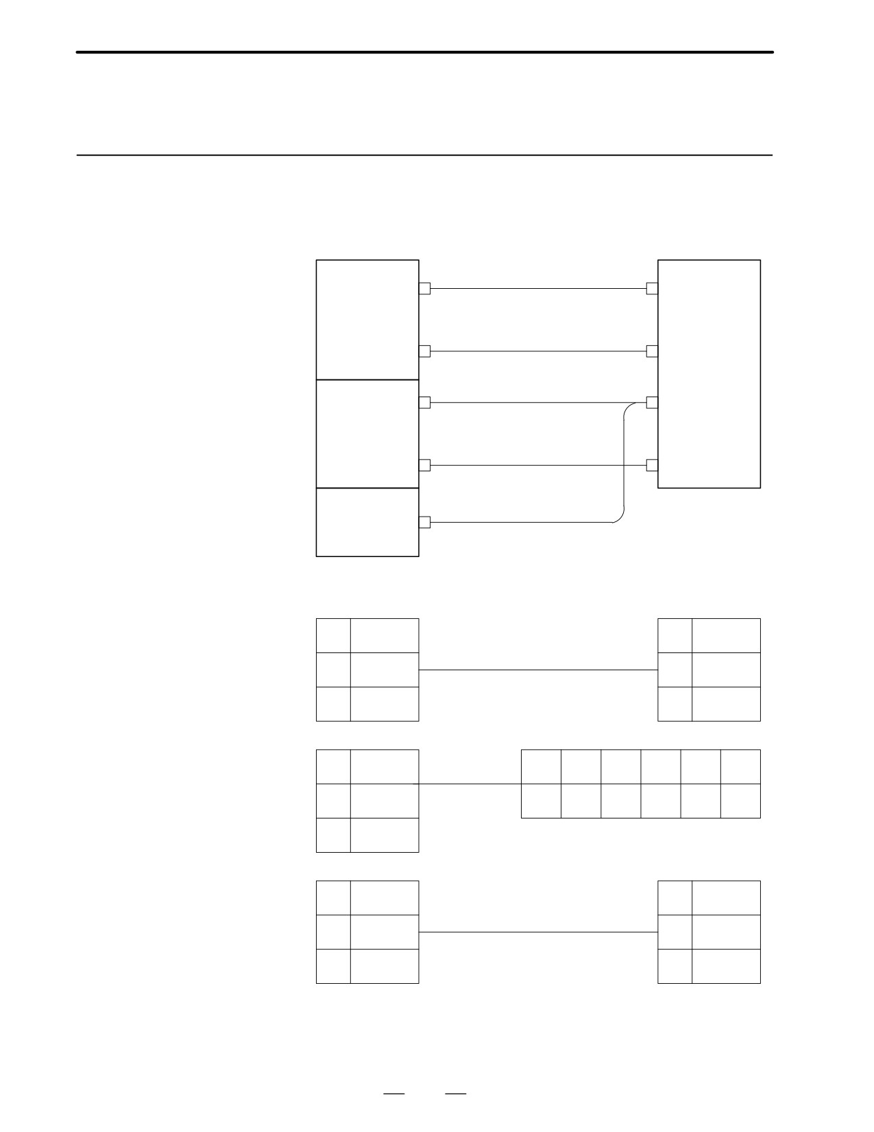
CRT/MDI unit
D Connection of Series 16
Power supply
CRT/MDI
CP4
(ON/OFF)
unit
unit ,
LCD/MDI
CP5(monochrome CRT : DC24V)
unit or PDP/
CP2 or CP3
CN2(CRT/PDP)
MDI unit
(Color CRT, LCD : AC200V) CP11(LCD)
CRT(JA1)
Without CAP-II
CN1
Main CPU board
MDI(JA2)
CK1
Option 1 board
CRT(JA1)
With CAP-II
D Terminal layout
CP2 or CP3
CN2 (CRT)
For 9″ color CRT
1
200A
or 9″ PDP
1
200A
or 14″ color CRT
2
200B
2
200B
3
G
3
G
CP5
CN2
For 9″ mono-
1
+24V
chrome CRT
1
2
3
4
5
6
2
0V
0V
0V
+24V
+24V
3
CRT
CP5
+24V
1
+24V
1
For 9.5″ LCD or
8.4″ LCD
2
0V
2
0V
3
3
99
2. HARDWARE
B-62445E/03
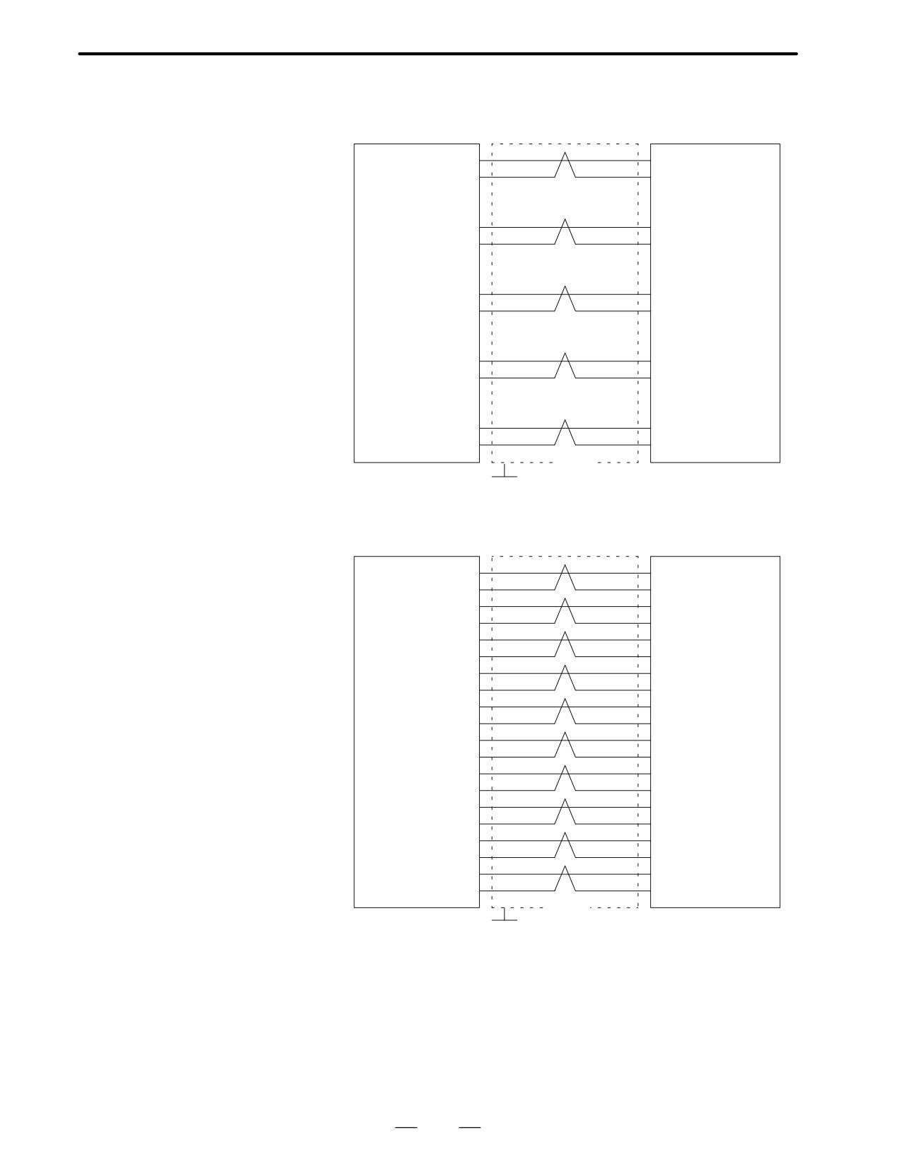
D Cable connection
JAI (For LCD)
CN1 (For CRT)
CRT(JA1)
VDR (01)
(01) VDR
0V (02)
(08) 0V
VDG (03)
(04) VDG
0V (04)
(11) 0V
VDB (05)
(05) VDB
0V (06)
(12) 0V
HSYNC (18)
(02) HSYNC
0V (14)
(09) 0V
VSYNC (12)
(03) VSYNC
0V (16)
(10) 0V
Shield
Connector : Half-pitch
Connector: MR20-pins(CRT)
(PCR)
G
Connector: Half-pitch
20-pins(LCD)
Recommended cable material:A66L-0001-0296 (Coaxial cable)
MDI(JA2)
CK1
*KEY00
(01)
(01) *KEY00
*KEY02
(02)
(02) *KEY02
*KEY04
(03)
(03) *KEY04
*KEY06
(04)
(04) *KEY06
*COM00 (05)
(05) *COM00
*COM02 (06)
(06) *COM02
*COM04 (07)
(07) *COM04
*COM06 (08)
(08) *COM06
*COM08 (09)
(09) *COM08
*COM10 (10)
(10) *COM10
*KEY01
(11)
(11) *KEY01
*KEY03
(12)
(12) *KEY03
*KEY05
(13)
(13) *KEY05
*KEY07
(14)
(14) *KEY07
*COM01 (15)
(15) *COM01
*COM03 (16)
(16) *COM03
*COM05 (17)
(17) *COM05
*COM07 (18)
(18) *COM07
*COM09 (19)
(18) *COM09
*COM11 (20)
(20) *COM11
Shield
Connector : Half-pitch
Connector: Half-pitch
G
20-pins(PCR)
20-pins(PCR)
Recommended cable material :
A66L-0001-0284#10P(#28AWG
10 Pairs)
100
2. HARDWARE
B-62445E/03
2.4.2
Reader/Puncher
Interface
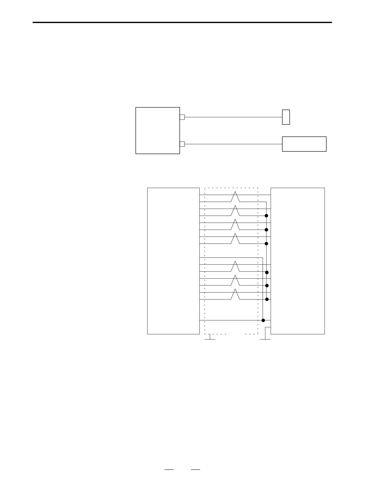
D Connection
R232-1(JD5A)
(Channel 1)
Main CPU board
Punch panel
R232-2(JD5B)
(Channel 2)
Tape reader etc.
D Cable connection
R232-1(JD5A)
R232-2(JD5B)
Punch panel
RD (01)
(03) RD
0V (02)
DR (03)
(06) DR
0V (04)
0V (06)
(05) CS
CD (07)
0V (08)
(08) CD
(09)
+24V (10)
SD (11)
0V (12)
(02) SD
ER (13)
0V (14)
(20) ER
RS (15)
0V (16)
(04) RS
(17)
(07) SG
(18)
+24V (19)
(20)
(25) +24V
(01) FG
Shield
Connector : Half-pitch
Connector DBM-25S
(PCR)
G
G
Recommended cable material:
A66L-0001-0284#10P(#28AWG
10 Pairs)
101
2. HARDWARE
B-62445E/03
2.4.3
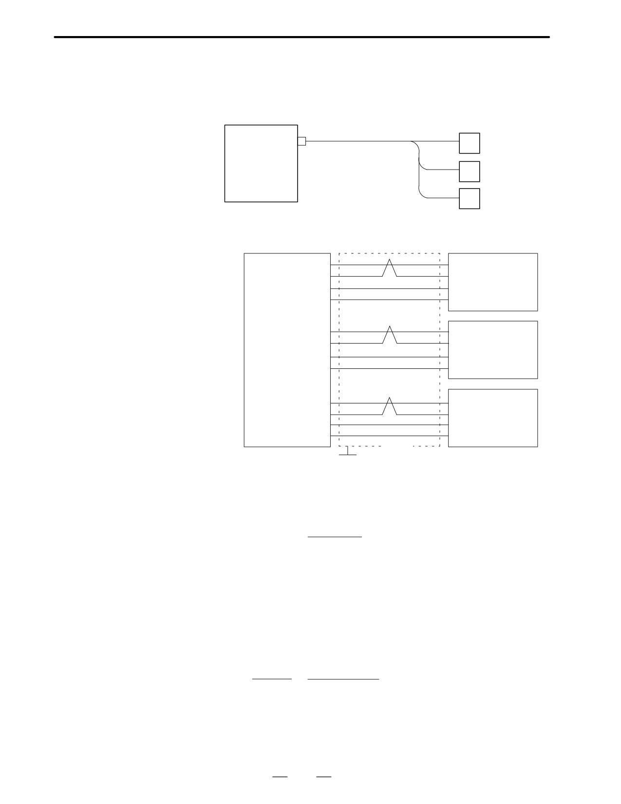
Manual Pulse Generator
D Connection
MPG(JA3)
Main CPU board
1st manual pulse
#1
generator
2nd manual pulse
#2
generator
3rd manual pulse
#3
generator
D Cable connection
MPG(JA3)
Manual pulse generator
HA1 (01)
(05) HA1
1st
HB1 (02)
(06) HB1
+5V (09)
(03) +5V
0V (12)
(04) 0V
HA2 (03)
(05) HA2
2nd
HB2 (04)
(06) HB2
+5V (18)
(03) +5V
0V (14)
(04) 0V
HA3 (05)
(05) HA3
3rd
HB3 (06)
(06) HB3
+5V (20)
(03) +5V
0V (16)
(04) 0V
Shield
Connector : Half-pitch
G
20-pins(Hirose)
Recommended cable :A66L-0001-0286(#20AWG
6, #24AWG
3 pairs)
D Voltage drop by cable
Restrict voltage drop by cable to less than 0.2V in accordance with
length
+5V/0V.
A R
2L
Voltage drop V =
m
Where A : manual pulse generator’s current (0.1A)
R : Registance per cable length
L : Cable length
m : No. of cables
When cable A66L-0001-0286 is used for one unit of manual pulse
generator, registance is 0.0394Ω/m and 3 cables are used. Therefore,
cable length can be extended up to 50 m according to the following
equation:
V m
0.2
3
L =
=
=76.75[m]
2A R
2
0.1
0.0394
102
2. HARDWARE
B-62445E/03
2.4.4
I/O LINK
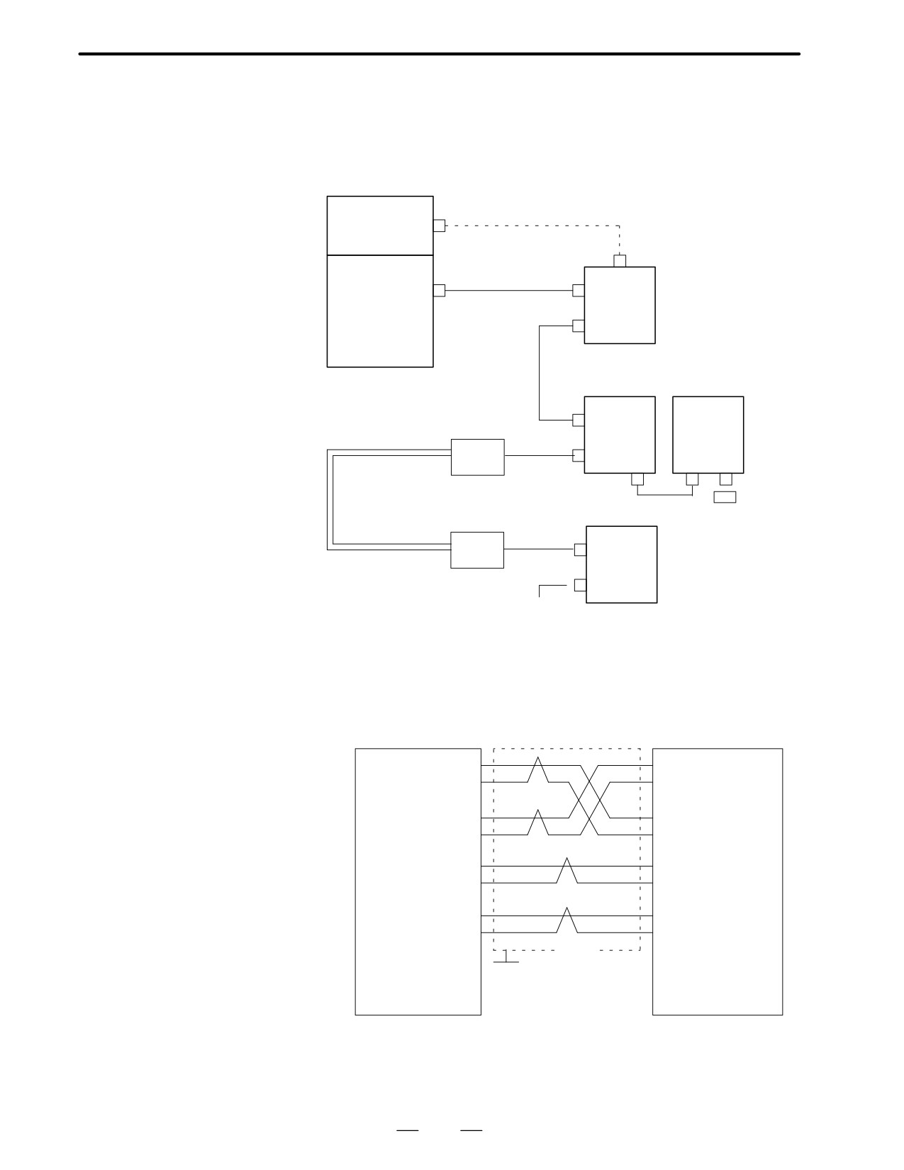
D Connection
Power supply unit
+24E(CP6)
· I/O Unit-A
· PCB for standard
machine operator’s
panel
Main CPU board
IO LINK (JD1A)
JD1B
Group #0
· Operator’s panel
or
connection unit
Option 3 boards
· Power Mate ,etc.
JD1A
PMC-RA : Main CPU
PMC-RB : Main CPU
JD1B
PMC-RC : Option 3
Optical I/O link
Group #1
adapter
(For I/O
JD1A
unit A)
O/E
Base #0
Base #1
Optical I/O link
Terminator
adapter
Optical fiber
JD1B
Group #2
O/E
JD1A
Expanded up to 16 Groups
D Cable connection within
group
IOLINK (JD1A)
JD1B
SIN (01)
(01) SIN
*SIN (02)
(02) *SIN
Twist pair
SOUT (03)
(03) SOUT
*SOUT (04)
(04) *SOUT
0V (11)
(11) 0V
0V (12)
(12) 0V
0V (13)
(13) 0V
0V (14)
(14) 0V
Shield
(+5V) (09)
(09)
(+5V)
(+5V) (18)
G
(18)
(+5V)
(+5V) (20)
(20)
(+5V)
Connector : Half-pitch
Connector : Half-pitch
20 pins(PCR)
20 pins(PCR)
Recommended cable:A66L-0001-0284 (#28AWG
10 pairs)
103
2. HARDWARE
B-62445E/03
Note
Connect +5V when optical I/O link adapter is used. Do not connect when metal cable is used.
When metal cable is used, cable length between units is extended by 10 m.
When optical I/O link adapter is used, cable length between units is extended by 200m.
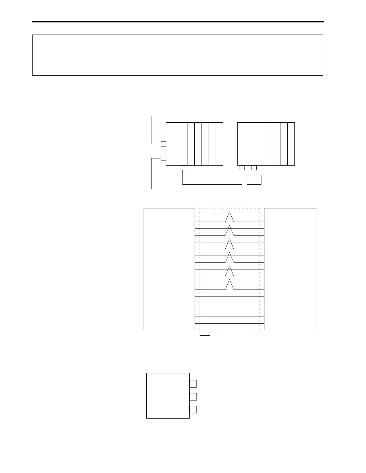
D Connection between
bases (with I/O unit-A)
From the last
Group
Base #0
Base #1
AIF01A
AIF01A
JD1B
JD1A
JD2
JD3
JD2
Terminator
To next Group
JD2
JD3
S1 (01)
(01) S1
*S1 (02)
(02) *S1
S2 (03)
(03) S2
*S2 (04)
(04) *S2
S3 (05)
(05) S3
*S3 (06)
(06) *S3
S4 (07)
(07) S4
*S4 (08)
(08) *S4
S5 (11)
(11)
S5
*S5 (12)
(12) *S5
S6 (13)
(13) S6
*S6 (14)
(14) *S6
ID1 (09)
(09) ID1
ID2 (17)
(17) ID2
ID3 (18)
(18) ID3
0V (15)
(15)
0V
0V (16)
(16)
0V
Shield
Connector : Half-pitch
Connector : Half-pitch
G
20-pins (PCR)
20-pins (PCR)
D Cable connection in the
terminator
JD2
TRM1 (04)
TRM1 (10)
TRM2 (12)
TRM2 (19)
TRM3 (14)
TRM3 (20)
Connector : Half-pitch
20-pins (PCR)
104
2. HARDWARE
B-62445E/03
2.4.5
When using the C series servo amplifier or α series servo amplifier (type
A interface), connect the serial pulse coder cable to the NC.
Servo Interface
When using the α series servo amplifier (type B interface), connect the
serial pulse coder cable to the servo amplifier module.
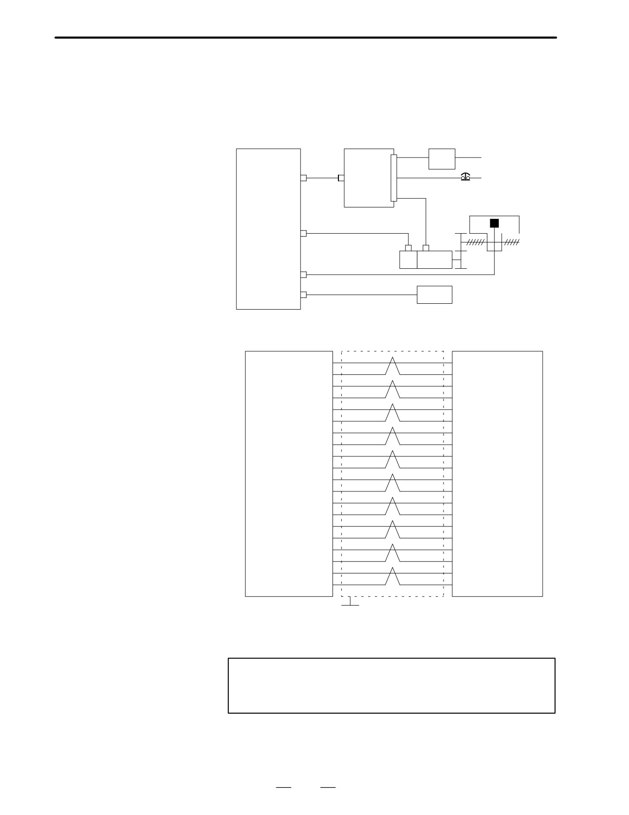
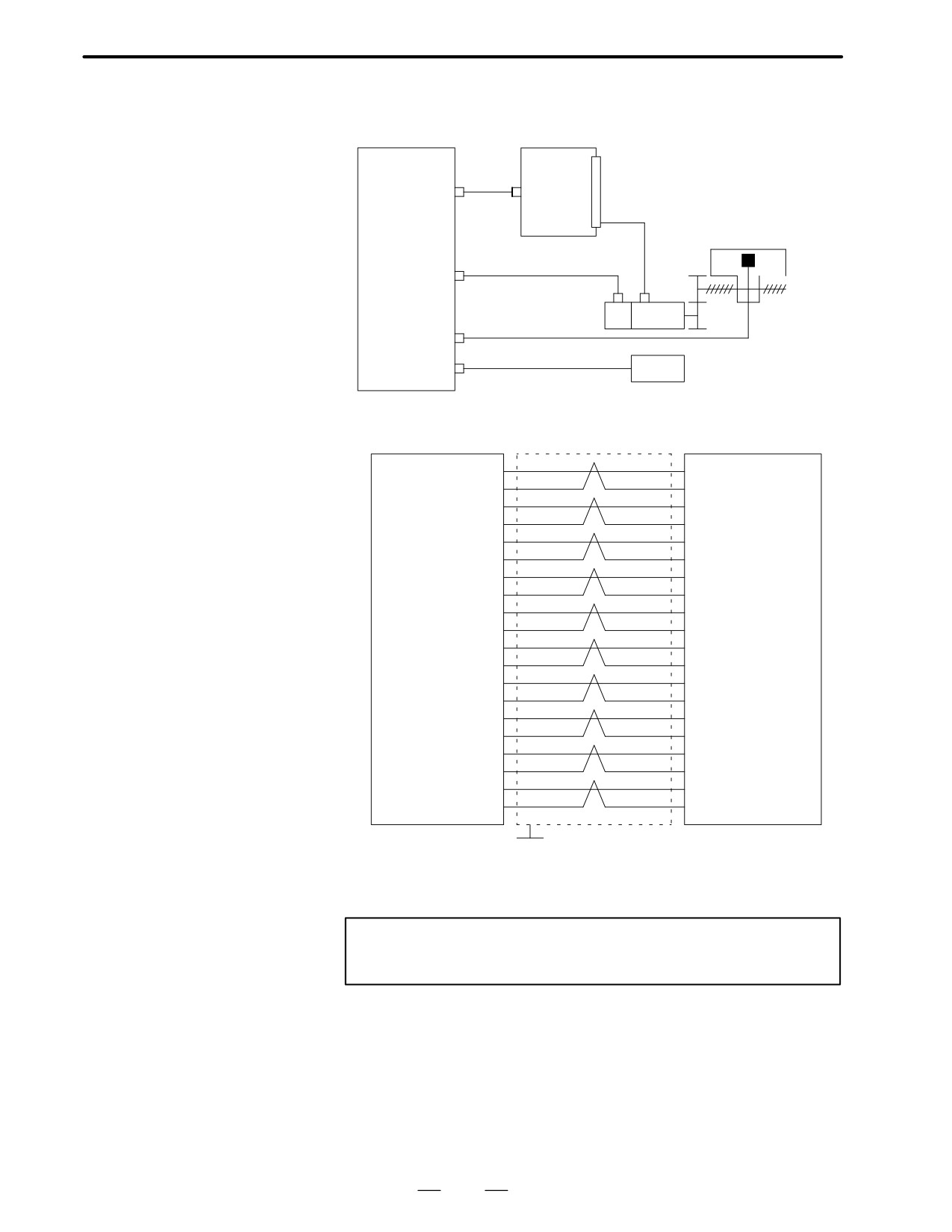
D Connection to C series
servo amplifier
AC reactor
T1
200VAC∼230VAC
Main CPU board
AMPx
S e r v o
Option 2 boards
(JVx)
amp.
Off by emergency stop
CN1
AC100V
Ž
Power line
Linear scale etc.
ENCx
x:1~8
(JFx)
ÔÔÔ
SCALEx
Servo
PC
(JF2x)
motor
APCBAT(JA4A, JA4B)
battery
6V
D Connection to cable
AMPx(JVx)
CN1
IRn (01)
(01) IRn
GDRn (02)
(02) GDRn
*PWMAn (03)
(03) *PWMAn
0V (04)
(04) COMAn
*PWMBn (05)
(05) *PWMBn
0V (06)
(06) COMBn
*PWMCn (07)
(07) *PWMCn
0V (08)
(08) COMCn
(09)
(09) GNDn *1
*MCONn (10)
(10) *MCONn
ISn (11)
(11) ISn
GDSn (12)
(12) GDSn
*PWMDn (13)
(13) *PWMDn
0V (14)
(14) COMDn
*PWMEn (15)
(15) *PWMEn
0V (16)
(16) COMEn
*PWMFn (17)
(17) *PWMFn
0V (18)
(18) COMFn
(19)
(19)
*DRDYn (20)
(20) *DRDYn
Shield
Connector : Half-
Connector : MR20-pin (S series servo amp.)
pitch 20-pin
G
Connector : Half-pitch 20-pin (C series servo amp.)
Recommended cable material : A66L-0001-0284#10P(#28AWG
10 pairs)
Notes
1
Not used for C series amplifier.
2
Suffix n in signal name is an axis number 1 to 8.
105
2. HARDWARE
B-62445E/03
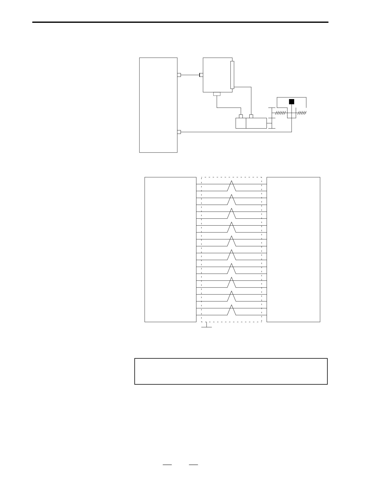
D Connection to α series
servo amplifier
For Series 16/160
(Interface type A)
MAIN-A
Main CPU board
AMPx
SVM
Option 2 boards
(JVx)
JVαB
Power line
Linear scale etc
ENCx
x:1~8
(JFx)
ÔÔÔ
SCALEx
Servo
PC
(JF2x)
motor
APCBAT(JA4A, JA4B)
battery
6V
D Connection to cable
AMPx(JVx)
JVxB
IRn (01)
(01) IRn
GDRn (02)
(02) GDRn
*PWMAn (03)
(03) *PWMAn
(04) COMAn
0V (04)
(05) *PWMBn
*PWMBn (05)
(06) COMBn
0V (06)
(07) *PWMCn
*PWMCn (07)
(08) COMCn
0V (08)
(09) GNDn *1
(09)
(10) *MCONn
*MCONn (10)
(11) ISn
ISn (11)
(12) GDSn
*PWMDn (13)
(13) *PWMDn
0V (14)
(14) COMDn
*PWMEn (15)
(15) *PWMEn
0V (16)
(16) COMEn
*PWMFn (17)
(17) *PWMFn
0V (18)
(18) COMFn
(19)
(19)
(20) *DRDYn
*DRDYn (20)
Shield
Connector : Half-
Connector : Half-pitch 20-pin
G
pitch 20-pin
Recommended cable material : A66L-0001-0284#10P(#28AWG
10 pairs)
Note
Suffix n in signal name is an axis number 1 to 8.
106
2. HARDWARE
B-62445E/03
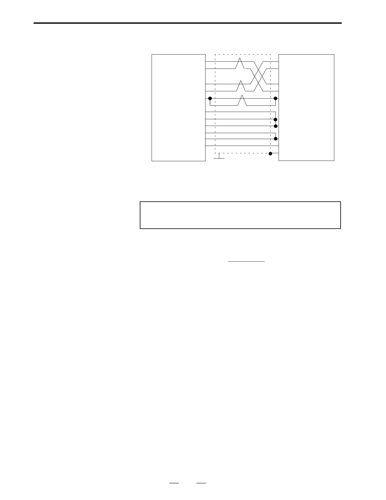
D Connection to α series
servo amplifier
For Series 16/160
(Interface type B)
MAIN-B and Series 18/180
Main CPU board
AMPx
Servo
Option 2 boards
(JSxA)
amp.
CN1
Power line
Linear scale etc
ÔÔÔ
SCALEx
Servo
PC
(JF2x)
motor
D Connection to cable
AMPx(JSxA)
CN1
IRn (01)
(01) IRn
GDRn (02)
(02) GDRn
*PWMAn (03)
(03) *PWMAn
(04) 0V
0V (04)
(05) *PWMCn
*PWMCn (05)
(06) 0V
0V (06)
(07) *PWMEn
*PWMEn (07)
(08) 0V
0V (08)
(09) *DRDYn
*DRDYn (09)
(10) *MCONn
*MCONn (10)
(11) ISn
ISn (11)
(12) GDSn
GDSn (12)
(13) *ELBLn
*ENBLn (13)
(14) 0V
0V (14)
(15) PDn
PDn (15)
(16) *PDn
*PDn (16)
(17) PREQn
*PREQn (18)
(18) *PREQn
0V (19)
(19) 0V
(20) *0V
*0V (20)
Shield
Connector : Half-
Connector : Half-pitch 20-pin
G
pitch 20-pin
Recommended cable material : A66L-0001-0284#10P(#28AWG
10 pairs)
Note
Suffix n in signal name is an axis number.
107
2. HARDWARE
B-62445E/03
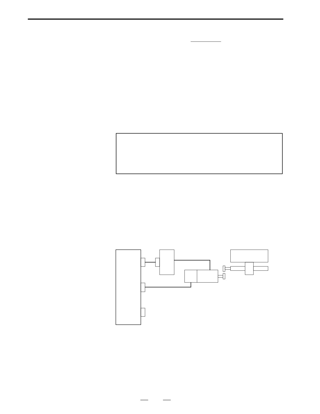
D Connection of serial
pulse coder
ENCx(JFx)
Serial pulse coder
SD (01)
(E) REQ
*SD (02)
(F)
*REQ
REQ (05)
(A) SD
*REQ (06)
(B)
*SD
+6V (07)
(T)
+6V
+5V (09)
+5V (18)
+5V (20)
(L)
+5V
0V (12)
0V (14)
(M)
0V
0V (16)
(U) OVA
(N) SHLD(Sheil
G
Connector : Half-pitch
Connector : CANON
20-pin
Recommended cable : A66L-0001-0286(#20AWG
6, #24AWG
10 pairs)
Note
Be sure to note voltage drop by cable resistance.
D Serial pulse coder A
0.40 R
2L
Voltage drop(Max) = 0.25[V] y
M
0.40
: Current consumed by pulse coder
R
: Resistance per unit length of cable [Ω/m]
L
: Cable length [m]
M : No. of wires to 5V and 0V
[Ex1]A66L-0001-0286(20/0.18,0.0394W/m) : L (Max)=23.79m
[Ex2]A66L-0001-0157(50/0.18,0.016W/m) : L (Max)=58.59m
However, as a cable of 11 dia. cannot be clamped with the half-pitch
connector, prepare a relaying connector or fabricate the cabel by
peeling off the sheeth and covering a heat-shrinkable tube.
When using the C series servo amplifier or series servo amplifier
(type A), connect the serial pulse coder to the NC.When using the
series servo amplifier (type B), connect the serial pulse coder to the
servo amplifier.
108
2. HARDWARE
B-62445E/03
D Serial pulse coder C
0.35 R
2L
Voltage drop (Max) = 0.20[V] y
M
0.35
: Current consumed by pulse coder
R
: Resistance per unit length of cable [Ω/m]
L
: Cable length [m]
M : No. of wires to 5V and 0V
[Ex1]A66L-0001-0286(20/0.18,0.0394W/m) : L (Max)=21.75m
[Ex2]A66L-0001-0157(50/0.18,0.016W/m) : L (Max)=53.57m
However, as a cable of 11 dia. cannot be clamped with the half-pitch
connector, prepare a relaying connector or fabricate the cabel by
peeling off the sheeth and covering a heat-shrinkable tube.
Note
When using the C series servo amplifier or α series servo
amplifier (type A), connect the serial pulse coder to the NC.
When using the α series servo amplifier (type B), connect
the serial pulse coder to the servo amplifier.
2.4.6
Connections by Type of
Detectors
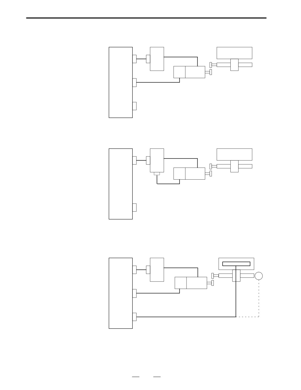
D Built-in pulse coder
Connection to C series
servo amplifier
Main CPU board
Servo amplifier
Table
AMP α
CN1
ÇÇÇÇÇÇ
Servo
PC
motor
ENC α
Position + speed+rotor position
SCALE α
109
2. HARDWARE
B-62445E/03
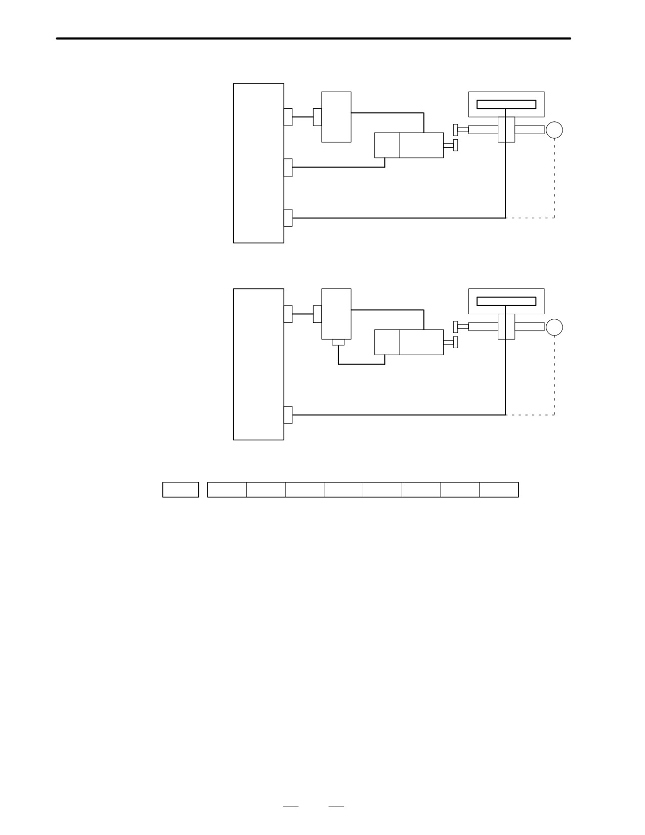
Connection to α series
servo amplifier
For MAIN-A
(Interface of type A)
of Series 16/160
SVM
Table
AMP α
CN1
ÇÇÇÇÇÇ
Servo
PC
ÇÇÇÇÇÇ
motor
ENC α
Position + speed+rotor position
SCALE α
Connection with α series
servo amplifier
For MAIN-B
of Series 16/160
(Interface of type B)
and Series 18/180
SVM
S Main CPU board
S Option2 board
Table
AMP α
JVαB
ÇÇÇÇÇÇ
JFα
Servo
ÇÇÇÇÇÇ
PC
motor
Position + speed+rotor position
SCALE α
D Separate type pulse
coder,Linear scale
Connection to C series
servo amplifier
Main CPU board
Servo amplifier
Linear scale
AMP α
CN1
ÇÇÇÇÇÇPC
Servo
PC
motor
ENC α
Velocity feedback+ rotor posi-
tion
SCALE α
Position feedback
Separate type PC
110
2. HARDWARE
B-62445E/03
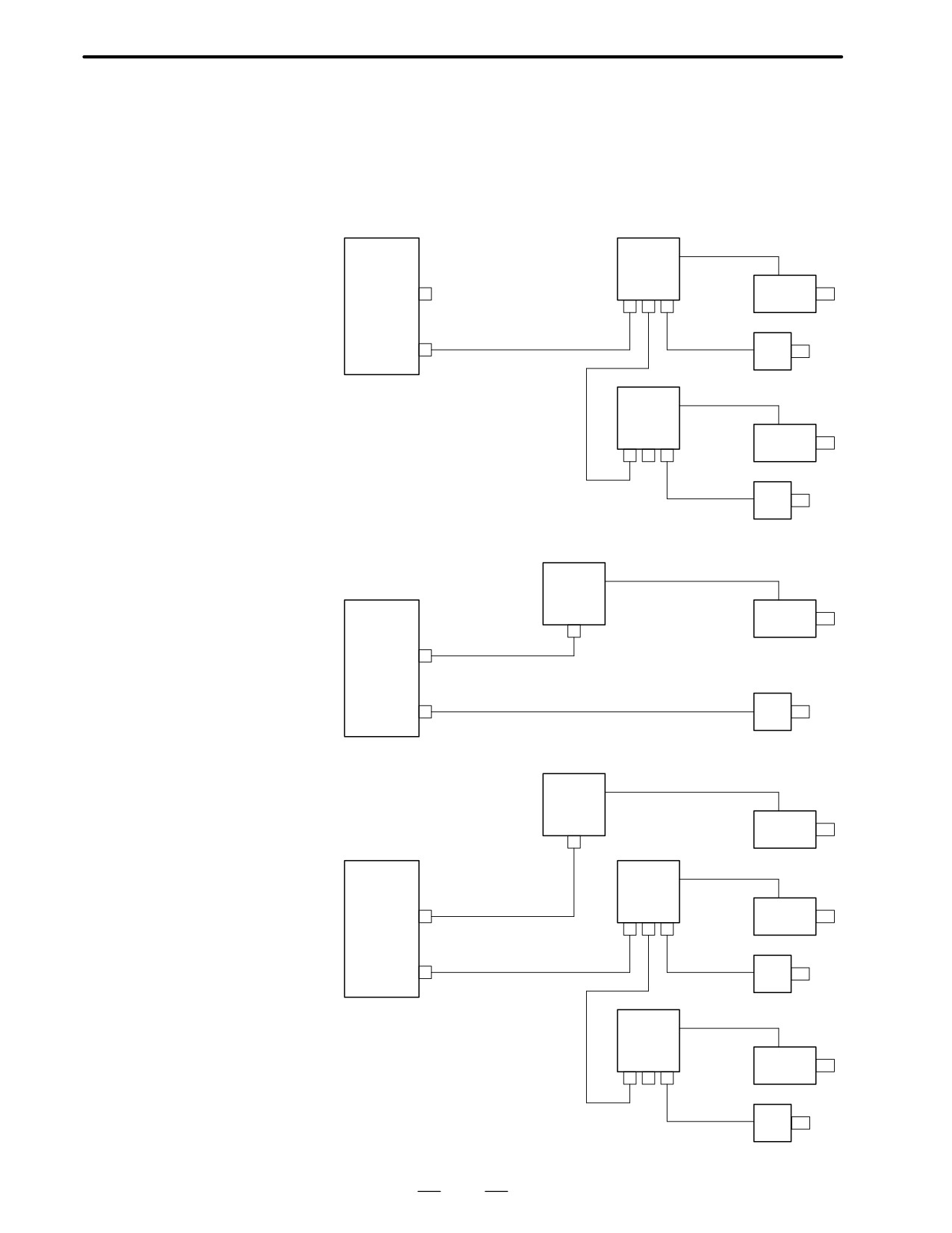
D Connection to α series
servo amplifier
SVM
Linear scale
S Main CPU board
(Interface of type A)
S Option board
AMP α
CN1
ÇÇÇÇÇÇ
PC
ÇÇÇÇÇÇ
PC
Servo
motor
ENC α
Velocity feedback+ rotor posi-
tion
SCALE α
Position feedback
Separate type PC
D Connection with α series
servo amplifier
SVM
Linear scale
(Interface of type B)
S Main CPU board
S Option2 board
AMP α
JVαB
JFα
ÇÇÇÇÇÇPC
PC
Servo
motor
Velocity feedback+ rotor posi-
tion
SCALE α
Position feedback
Separate type PC
D Associated parameters
#7
#6
#5
#4
#3
#2
#1
#0
1815
OPTx
#1 (OPTx)
: Separate type pulse coder of position detector is :
0 : used
1 : not used
111
2. HARDWARE
B-62445E/03
2.4.7
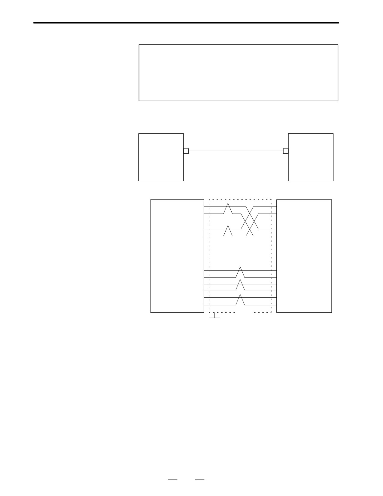
Combining Serial
Spindle and Analog
Spindle
D Only serial spindle is
used
Main CPU
Serial
board
spindle
#1
Spindle
A-OUT1
motor
(JA8A)
SPDL-1
PC
(JA7A)
(Note)
Serial
spindle
#2
Spindle
motor
PC
D Only analog spindle is
used
Analog
spindle
Main CPU
Spindle
board
motor
A-OUT1
(JA8A)
SPDL-1
PC
(JA7A)
D Serial spindle and
analog spindle are used
Analog
spindle
Spindle
motor
Main CPU
Serial
board
spindle
#1
Spindle
A-OUT1
motor
(JA8A)
SPDL-1
PC
(JA7A)
(Note)
Serial
spindle
#2
Spindle
motor
PC
112
2. HARDWARE
B-62445E/03
Note
When a serial spindle amplifier is used, an optical I/O link
adapter must be used to connect the main CPU board to the
spindle amplifier. When the a series spindle amplifier is
used, the main CPU board and spindle amplifier must be
connected using a metallic cable.
2.4.8
SPDL-x
Connection to α serial
Main CPU board
(JA7A, B)
Option 2 board
JA7B
Spindle Amplifier
SPM
x:1, 2
JD1(Optical I/O link
SPDL-x (JA7A, B)
adapter)
SIN (01)
(01) SIN
*SIN (02)
(02) *SIN
SOUT (03)
(03) SOUT
*SOUT (04)
(04) *SOUT
0V (11)
(11) 0V
0V (12)
(12) 0V
0V (13)
(13) 0V
0V (14)
(14) 0V
0V (15)
(15) 0V
0V (16)
(16) 0v
Shield
Connector:Half-pitch
Connector:Half-pitch
G
20-pin
20-pins
Recommended cable:A66L-0001-0284#10P(#28AWG
10pairs)
113