FANUC Series 0i-MODEL D, Series 0i Mate-MODEL D. For Lathe System USER’S MANUAL - page 19
B.DIFFERENCES FROM SERIES 0i-C APPENDIX
B-64304EN-1/01
Function
Series 0i-C
Series 0i-D
Setting to disable
-
Set 1 in bit 0 (CNI) of parameter No.
-
Not available.
interference checking
5008.
(Bit 0 (CNI) of parameter No. 5008 is
and to delete
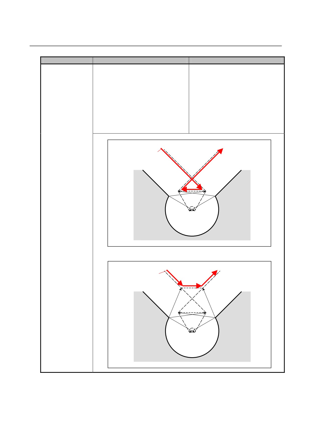
In the example below, an interference
not available.)
interfering vectors
check is made on the vectors inside V1
To prevent overcutting, the interference
and V4, and the interfering vectors are
check avoidance function (bit 5 (CAV)
deleted. As a result, the tool center
of parameter No. 19607) is used.
path is from V1 to V4.
In the example below, interference
occurs between V1 and V4 and between
V2 and V3. Therefore, vectors VA and
VB are created. The tool center path
is from VA to VB.
[In the case of Series 0i-C]
Tool center path
Programmed path
V4
V1
V3
V
2
[In the case of Series 0i-D]
Tool center path
Programmed path
V
A
VB
V
4
V1
V3
V2
- 524 -
B-64304EN-1/01
APPENDIX B.DIFFERENCES FROM SERIES 0i-C
Function
Series 0i-C
Series 0i-D
Number of blocks to
-
Always 3 blocks
-
The number can be set in parameter
be read in the cutter
No. 19625. The specifiable range is 3
compensation/tool
to 8 blocks.
nose radius
If the parameter is not set (0 is set), the
compensation mode
same number as Series 0i-C (3 blocks)
is assumed.
When circular
-
Alarm PS0038 is issued, and the tool
-
Alarm PS0041 is issued, and the tool
interpolation is
stops at the end point of the block
stops at the start point of the block
specified that causes
preceding the circular interpolation
preceding the circular interpolation
the center to coincide
block.
block.
with the start or end
point during the cutter
compensation/tool
nose radius
compensation mode
Behavior when
-
Depends on bit 2 (CCN) of parameter
-
Bit 2 (CCN) of parameter No. 5003 is
automatic reference
No. 5003.
not available. The tool always
position return is
behaves as when CCN is set to 1.
specified during the
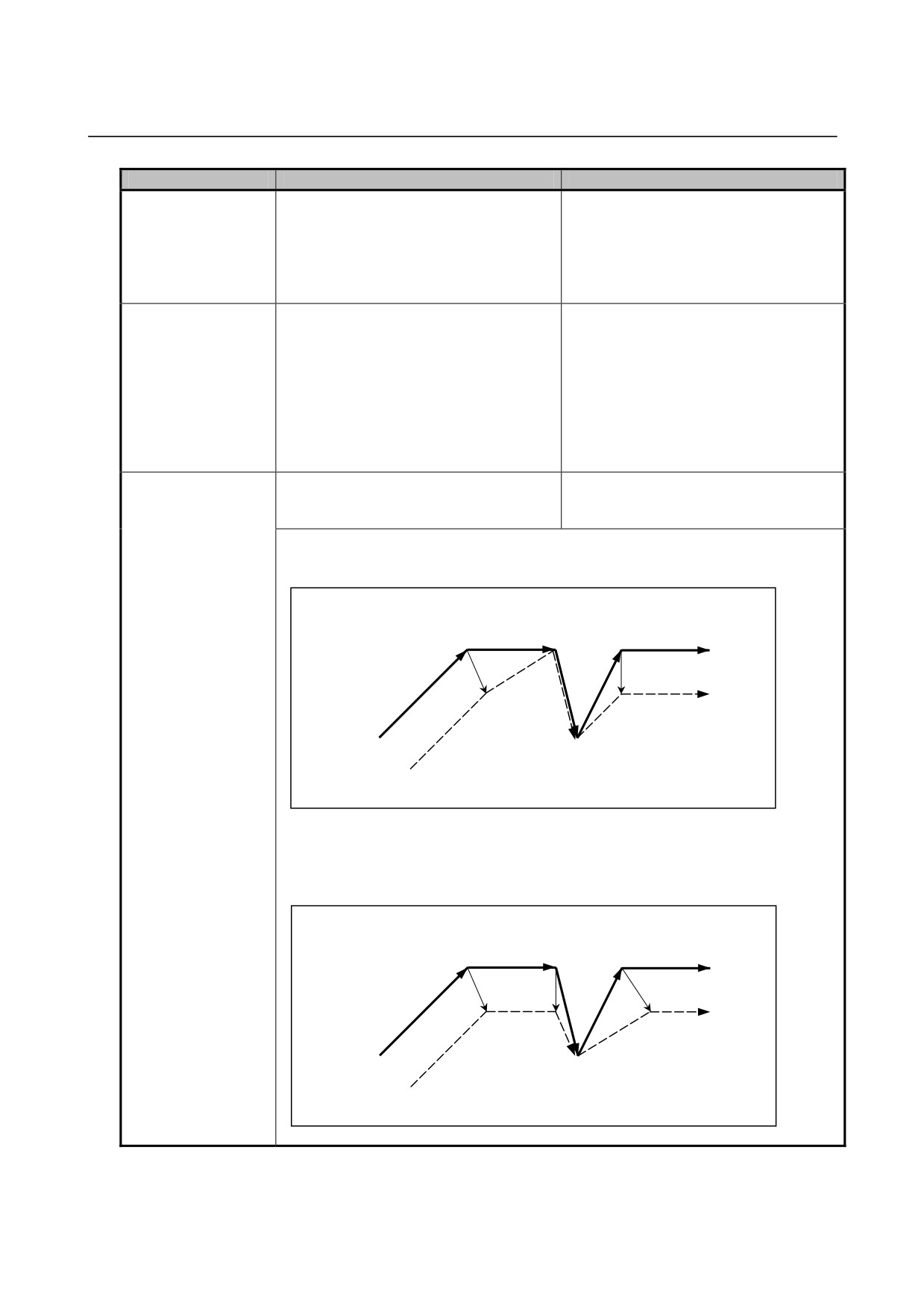
[When CCN = 0]
cutter
The offset vector is canceled when the tool moves to the middle point.
compensation/tool
Also, the start-up operation is performed from the reference position.
nose radius
Intermediate
compensation mode
point
S
G28
S
S
G01
r
G00
S
Reference position
(G42 G01)
[When CCN = 1 or for Series 0i-D]
The offset vector is not canceled when the tool moves to the middle point; it is
canceled when the tool moves to the reference position.
Also, the tool moves from the reference position to the next intersection point.
Intermediate
point
S
G28
S
S
G01
r
G00
S
Reference position
(G42 G01)
- 525 -
B.DIFFERENCES FROM SERIES 0i-C APPENDIX
B-64304EN-1/01
Function
Series 0i-C
Series 0i-D
Travel distance
-
Depends on bit 5 (QCR) of parameter
-
Bit 5 (QCR) of parameter No. 5008 is
judgment method for
No. 5008.
not available. The tool always
circular interpolation in
behaves as when QCR is set to 1.
cutter
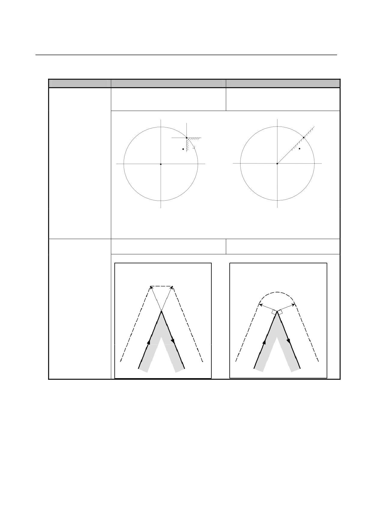
[When QCR = 0]
[When QCR = 1 or for Series 0i-D]
compensation/tool
B
C
B
L
nose radius
Start point
compensation
Start point
D
A
End
End
A
point
point
Center
Center
If the end point is on side A when viewed
If the end point is on side A of line L
from the start point, the travel distance is
connecting the start point and center, the
small. If it is on side B, C, or D, the tool
travel distance is small. If it is on side B,
has traveled almost one round.
the tool has traveled almost one round.
Compensation vector
-
Connected by linear interpolation.
-
Depends on bit 2 (CCC) of parameter
connection method
No. 19607.
when the tool travels
[When CCC = 0 or for Series 0i-C]
[When CCC = 1]
around an external
Connect vectors by linear
Connect vectors by circular
corner during the
interpolation
interpolation
cutter
compensation/tool
nose radius
compensation mode
- 526 -
B-64304EN-1/01
APPENDIX B.DIFFERENCES FROM SERIES 0i-C
Function
Series 0i-C
Series 0i-D
Virtual tool tip
-
Virtual tool tip directions 1 to 8 can be
-
All virtual tool tip directions can be used
direction and plane
used only for the G18 (Z-X) plane.
for the G17, G18, and G19 planes.
selection
When the virtual tool tip direction is 0 or
9, compensation can be performed for
the G17 and G19 planes as well.
Tool nose radius
-
[Outer surface turning/boring cycle
-
[Outer surface turning/boring cycle
center path for tool
(G90)]
(G90)]
nose radius
Tool nose radius center path
Tool nose radius center path
compensation in a
Tool nose radius center path
Tool nose radius
canned cycle (G90 or
0
4,8,3
0
center path
G94)
8
8
3
5,0,7
4
3
All tool noses
4
5
7
5
7
2
1
6
2
1,6,2
1
6
All tool
4,5,1
8,0,6
All tool noses
All tool
noses
3,7,2
noses
Programmed path
Programmed path
-
[Edge cutting cycle (G94)]
-
[Edge cutting cycle (G94)]
Tool nose radius center path
Tool nose radius center path
Tool nose radius center path
Tool nose radius
0
4,8,3
0
center path
8
8
3
4
3
5,0,7
4
All tool noses
5
7
5
7
2
1
2
1,6,2
1
6
6
All tool
All tool
4,5,1
8,0,6
All tool noses
noses
noses
3,7,2
Programmed path
Programmed path
* Numbers 0 to 8 in the figure are virtual tool tip numbers.
Start-up/cancellation
-
The start-up/cancellation type cannot
-
Depends on bit 0 (SUP) and bit 1
type of tool nose
be set.
(SUV) of parameter No. 5003.
radius compensation
When SUV and SUP are respectively
set to 0 and 1 (type B), the processing
is the same as Series 0i-C.
B.45.2 Differences in Diagnosis Display
None.
- 527 -

B.DIFFERENCES FROM SERIES 0i-C APPENDIX
B-64304EN-1/01
B.46 CANNED CYCLE FOR DRILLING
B.46.1 Differences in Specifications
Function
Series 0i-C
Series 0i-D
M05 output in a
-
Make a selection using bit 6 (M5T) of
-
Make a selection using bit 3 (M5T) of
tapping cycle
parameter No. 5101.
parameter No. 5105.
Bit 6 (M5T) of parameter No. 5101
Bit 3 (M5T) of parameter No. 5105
When the rotation direction of the spindle is
When the rotation direction of the spindle is
changed from forward rotation to reverse
changed from forward rotation to reverse
rotation or from reserve rotation to forward
rotation or from reserve rotation to forward
rotation in a tapping cycle (G84/G74 with
rotation in a tapping cycle (G84/G74 with
the M series, or G84/G88 with the T
the M series, or G84/G88 with the T
series):
series):
0: M05 is output before output of M04 or
0: M05 is not output before output of M04
M03.
or M03.
1: M05 is not output before output of M04
1: M05 is output before output of M04 or
or M03.
M03.
NOTE
This parameter corresponds to bit 6 (M5T)
of parameter No. 5101 of Series 0i-C.
With the T series, the logic of the values 0
and 1 is opposite from that of Series 0i-C.
Behavior when K0 is
-
Make a selection using bit 5 (K0E) of
-
Make a selection using bit 4 (K0D) of
specified for the
parameter No. 5102.
parameter No. 5105 for both T series
number of repetitions
and M series.
K
Bit 5 (K0E) of parameter No. 5102
When K0 is specified in a drilling canned
Bit 4 (K0D) of parameter No. 5105
cycle (G80 to G89):
When K0 is specified in a drilling canned
0: One drilling operation is performed.
cycle (G80 to G89):
1: Drilling operation is not performed, and
0: Drilling operation is not performed, and
only drilling data is stored.
only drilling data is stored.
1: One drilling operation is performed.
NOTE
With the T series, the logic of the values 0
and 1 is opposite from that of bit 5 (K0E) of
parameter No. 5102 of Series 0i-C.
Behavior of the first
-
The behavior can be selected using bit
-
While bit 1 (NRF) of parameter No.
positioning command
1 (NRF) of parameter No. 3700.
3700 exists, the normal positioning
(G00) for a Cs contour
operation is performed in a canned
control axis in a
Bit 1 (NRF) of parameter No. 3700
cycle, regardless of the setting of this
canned cycle
After a serial spindle is changed to a Cs
parameter bit.
contour control axis, the first move
command:
0: Performs the normal positioning
operation after executing the reference
position return operation.
1: Performs the normal positioning
operation.
- 528 -
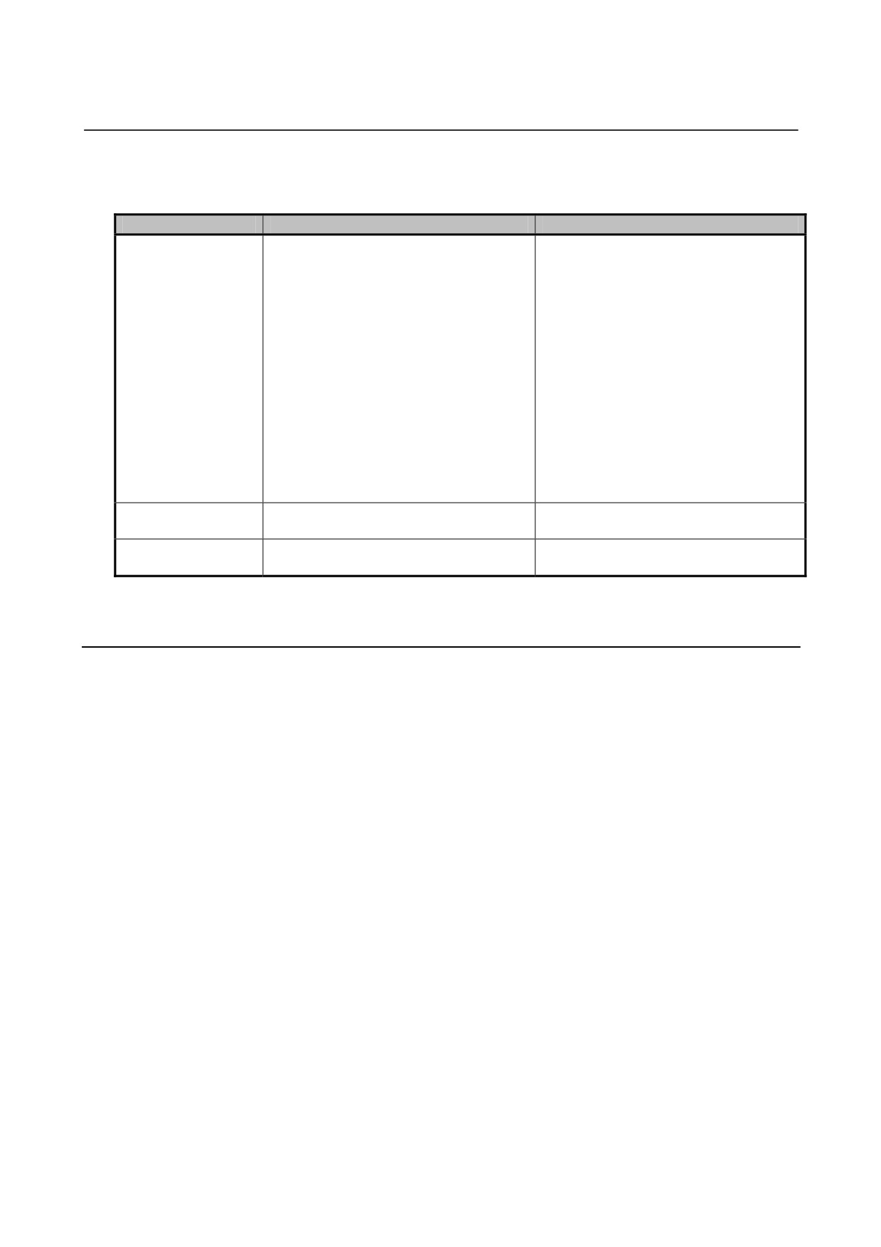
B-64304EN-1/01
APPENDIX B.DIFFERENCES FROM SERIES 0i-C
Function
Series 0i-C
Series 0i-D
Retraction in a boring
-
Select the retraction operation using bit
-
Bit 1 (BCR) of parameter No. 5104 is
cycle (G85, G89)
1 (BCR) of parameter No. 5104.
not available.
The retraction operation is always
Bit 1 (BCR) of parameter No. 5104
performed at the cutting feedrate.
The retraction operation in a boring cycle is
In this case, the cutting feedrate of the
performed: at
retraction operation can be multiplied
0: Cutting feedrate
by the override value set in parameter
In this case, the cutting feedrate of the
No. 5149. The override value range is
retraction operation can be multiplied by
1% to 2000%.
the override value set in parameter No.
5121. The override value range is
100% to 2000%.
1: Rapid traverse rate
In this case, rapid traverse override is
also enabled.
Clearance value in a
-
Set the value in parameter No. 5114.
-
Set the value in parameter No. 5115.
peck drilling cycle
Drilling axis in the
-
Y axis cannot be used as a drilling axis.
-
Y axis can be used as a drilling axis.
Series 10/11 format
P/S alarm No. 028 is issued.
B.46.2 Differences in Diagnosis Display
None.
- 529 -

B.DIFFERENCES FROM SERIES 0i-C APPENDIX
B-64304EN-1/01
B.47 CANNED CYCLE /MULTIPLE REPETITIVE CANNED
CYCLE
B.47.1 Differences in Specifications
Function
Series 0i-C
Series 0i-D
Machining plane
-
The plane on which the canned cycle is
-
The plane on which the canned cycle
performed is always the ZX plane.
ca be selected arbitrarily (including a
parallel axis).
Note that, with G code system A, an
axis whose name is U, V, or W cannot
be set as a parallel axis.
Address R setting unit
-
The setting unit common to all axes is
-
The setting unit applies to a different
(Address I, J, or K for
used.
axis depending on the machining plane
the Series 10/11
and the command.
format)
Second axis of the axes comprising
the machining plane for G90 and G92
First axis of the axes comprising the
machining plane for G94
Application of tool
-
Refer to Section 4.1.5, "CANNED CYCLE AND TOOL NOSE RADIUS
nose radius
COMPENSATION" in "USER'S MANUAL (T SERIES)" (B-64304EN-1). The
compensation
differences in specifications are detailed.
Inch threading by
-
Threading is performed as the lead
-
Inch threading is performed.
address E (Series
threading command of address F.
10/11 format)
Behavior of the first
-
The behavior can be selected using bit
-
While bit 1 (NRF) of parameter No.
positioning command
1 (NRF) of parameter No. 3700.
3700 exists, the normal positioning
(G00) for a Cs contour
operation is performed in a canned
control axis in a
Bit 1 (NRF) of parameter No. 3700
cycle, regardless of the setting of this
canned cycle
After a serial spindle is changed to a Cs
parameter bit.
contour control axis, the first move
command:
0: Performs the normal positioning
operation after executing the reference
position return operation.
1: Performs the normal positioning
operation.
B.47.2 Differences in Diagnosis Display
None.
- 530 -

B-64304EN-1/01
APPENDIX B.DIFFERENCES FROM SERIES 0i-C
B.48 CANNED GRINDING CYCLE
B.48.1 Differences in Specifications
Function
Series 0i-C
Series 0i-D
Grinding axis
-
The grinding axis is always the Z axis.
-
Set the grinding axes for the individual
specification
canned grinding cycles in parameter
Nos. 5176 to 5179.
If the same axis number as the cutting
axis is specified in any of these
parameters, or if a canned grinding
cycle is executed when 0 is set, alarm
PS0456 is issued.
Behavior of the first
-
The behavior can be selected using bit
-
While bit 1 (NRF) of parameter No.
positioning command
1 (NRF) of parameter No. 3700.
3700 exists, the normal positioning
(G00) for a Cs contour
operation is performed in a canned
control axis in a
Bit 1 (NRF) of parameter No. 3700
cycle, regardless of the setting of this
canned cycle
After a serial spindle is changed to a Cs
parameter bit.
contour control axis, the first move
command:
0: Performs the normal positioning
operation after executing the reference
position return operation.
1: Performs the normal positioning
operation.
Exclusive control
-
When the grinding canned cycle option
-
When the grinding canned cycle option
against the multiple
is specified, the multiple respective
is specified, select whether to use the
respective canned
canned cycle (standard function) cannot
multiple respective canned cycle
cycle (standard
be used.
(standard function) or grinding canned
function)
cycle, by using bit 0 (GFX) of
parameter No. 5106.
Bit 0 (GFX) of parameter No. 5106
When the grinding canned cycle option is
specified, the G71, G72, G73, and G74
commands are intended for:
0: Multiple respective canned cycle.
1: Grinding canned cycle.
B.48.2 Differences in Diagnosis Display
None.
- 531 -
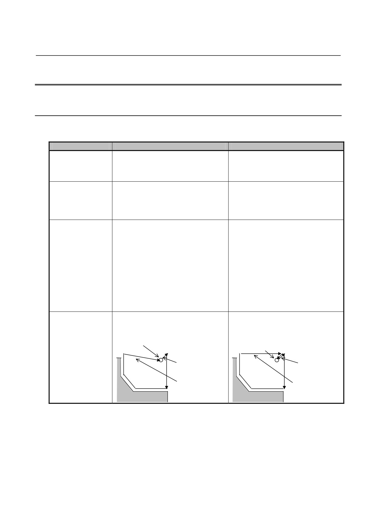
B.DIFFERENCES FROM SERIES 0i-C APPENDIX
B-64304EN-1/01
B.49 MULTIPLE RESPECTIVE CANNED CYCLE FOR TURNING
B.49.1 Differences in Specifications
Differences common to the Series 0 standard format and Series 10/11 format
Function
Series 0i-C
Series 0i-D
Specifiable plane
-
The cycle can be specified for a Z-X
-
The cycle can be specified for an
plane, with the X axis set as the first
arbitrary plane selected with the basic
axis and the Z axis set as the second
three axes and their parallel axes.
axis.
Specification for a
-
Not allowed.
-
For G code system A, the cycle can be
plane including a
specified when the name of the parallel
parallel axis
axis is other than U, V, or W.
(To use U, V, or W as an axis name is
not allowed for G code system A.)
Behavior of the first
-
The behavior can be selected using bit
-
While bit 1 (NRF) of parameter No.
positioning command
1 (NRF) of parameter No. 3700.
3700 exists, the normal positioning
(G00) for a Cs contour
operation is performed in a canned
control axis in a
Bit 1 (NRF) of parameter No. 3700
cycle, regardless of the setting of this
canned cycle
After a serial spindle is changed to a Cs
parameter bit.
contour control axis, the first move
command:
0: Performs the normal positioning
operation after executing the reference
position return operation.
1: Performs the normal positioning
operation.
Cycle start point
-
The tool returns directly to the cycle
-
The tool returns to the cycle start point
return path when the
start point.
via a point offset by the finishing
finishing allowance is
allowance.
specified in G71 or
Cycle start point
Cycle start point
G72
Finishing
Finishing
allowance
allowance
The tool returns to
the cycle start point
Return to the
via a point offset by
start point
the finishing
allowance.
- 532 -
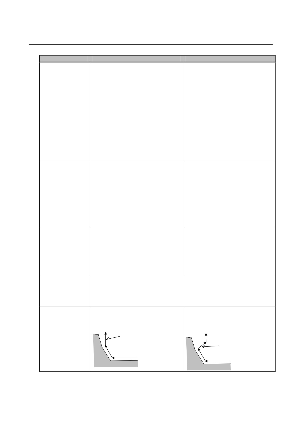
B-64304EN-1/01
APPENDIX B.DIFFERENCES FROM SERIES 0i-C
Function
Series 0i-C
Series 0i-D
Monotonous
-
Depends on bit 1 (MRC) of parameter
-
Bit 1 (MRC) of parameter No. 5102 is
increase/decrease
No. 5102.
not available.
check in G71/G72
If monotonous increase or decrease is
type I
Bit 1 (MRC) of parameter No. 5102
not specified for the first axis direction
(multiple respective
When any target figure other than
of the plane, alarm PS0064 is issued.
canned cycle for
monotonous increase or decrease is
If monotonous increase or decrease is
turning)
specified in a multiple respective canned
not specified for the second axis
cycle for turning (G71 or G72):
direction of the plane, alarm PS0329 is
0: An alarm is not issued.
issued.
1: Alarm PS0064 is issued.
Note that, by setting a permissible
amount in parameter Nos. 5145 and
5146, it is possible to prevent the alarm
from occurring, even if the monotonous
increase/decrease condition is not met,
as long as the permissible amount is
not exceeded.
Monotonous
-
Not checked.
-
Always checked.
increase/decrease
Bit 1 (MRC) of parameter No. 5102
If monotonous increase or decrease is
check in G71/G72
does not take effect for multiple
not specified for the first axis direction
type II
respective canned cycle for turning II
of the plane, alarm PS0064 is issued.
(multiple respective
(type II).
Note that, by setting a permissible
canned cycle for
amount in parameter No. 5145, it is
turning II)
possible to prevent the alarm from
occurring, even if the monotonous
increase/decrease condition is not met,
as long as the permissible amount is
not exceeded.
Roughing after start
-
Not performed.
-
[Multiple respective canned cycle for
point return by G71 or
turning I (type I)]
G72
Depends on bit 1 (RF1) of parameter
No. 5105.
[Multiple respective canned cycle for
turning II (type II)]
Depends on bit 2 (RF2) of parameter
No. 5105.
Bit 1 (RF1) of parameter No. 5105
Bit 2 (RF2) of parameter No. 5105
In the multiple repetitive canned cycle (T
In the multiple repetitive canned cycle (T
series) (G71/G72) of type I, roughing is:
series) (G71/G72) of type II, roughing is:
0: Performed.
0: Performed.
1: Not performed.
1: Not performed.
Retraction operation
-
The tool retracts in the X axis direction
-
After chamfering, the tool first retracts
at the bottom of a hole
after chamfering.
in the 45-degree direction and then in
in G71/G72 type II
the second axis direction of the plane.
(multiple respective
canned cycle for
X axis
turning II)
direction
45-degree
direction
- 533 -
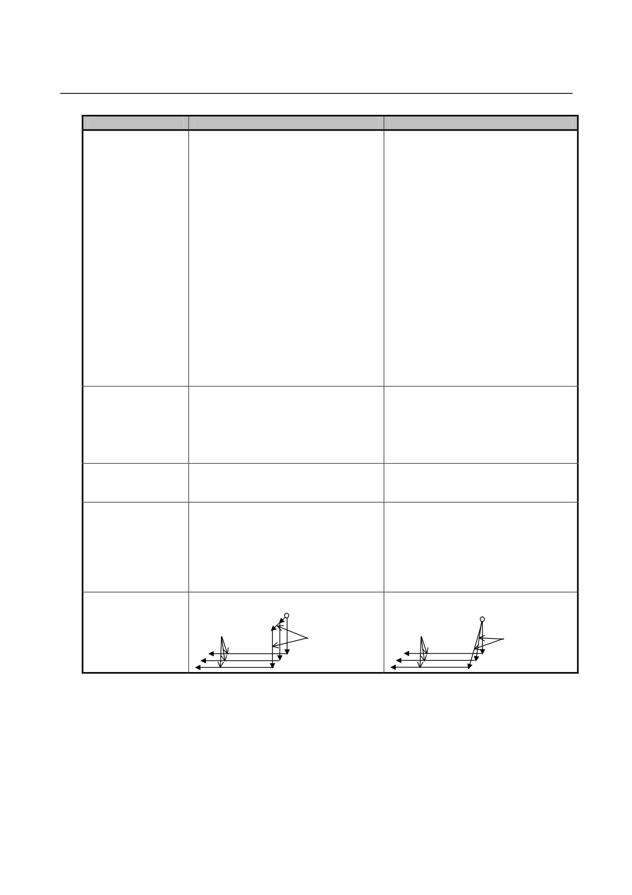
B.DIFFERENCES FROM SERIES 0i-C APPENDIX
B-64304EN-1/01
Function
Series 0i-C
Series 0i-D
G70 to G76
-
[G70 command]
-
Bit 4 (RFC) of parameter No. 5102 is
commands during the
Tool nose radius compensation is
not available.
tool nose radius
performed.
[G70 to G73 commands]
compensation mode
[G71 to G73 commands]
Tool nose radius compensation is
While tool nose radius compensation is
performed.
not performed, it is possible to apply
[G74 to G76 commands]
tool nose radius compensation partially
Tool nose radius compensation is not
by setting bit 4 (RFC) of parameter No.
performed.
5102.
Bit 4 (RFC) of parameter No. 5102
For a G71 or G72 semi-finished shape or a
G73 cutting pattern, tool nose radius
compensation is:
0: Not performed.
1: Performed.
[G74 to G76 commands]
Tool nose radius compensation is not
performed.
Positioning in G70 to
-
Non-linear type positioning is always
-
[Start point return by G70]
G76 cycle operations
used, regardless of the setting of bit 1
Non-linear type positioning is always
(LRP) of parameter No. 1401.
used.
[Other positioning operations]
Depends on bit 1 (LRP) of parameter
No. 1401.
T code specified in
-
Invalid
-
Valid
the same block as
G74 or G75
Chamfering and
-
Cannot be specified.
-
Can be specified.
corner R commands
Note that the last block of the target
and direct drawing
figure program must not be in the
dimension
middle of the chamfering, corner R, or
programming
direct drawing dimension programming
command for a target
command.
figure program
Approach to the
-
Approach by two cycles
-
Approach by one cycle
threading start point in
G76
Threading
Threading
Approach by
Approach by
two cycles
one cycle
- 534 -
B-64304EN-1/01
APPENDIX B.DIFFERENCES FROM SERIES 0i-C
Differences regarding the Series 0 standard format
Function
Series 0i-C
Series 0i-D
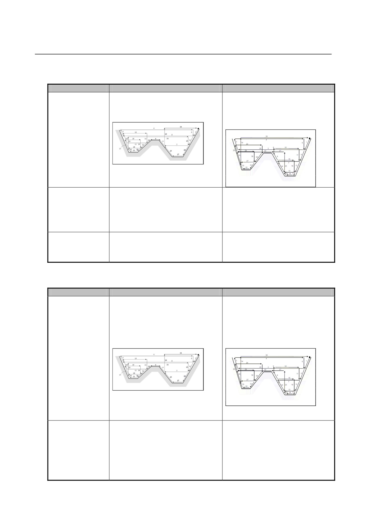
Pocketing path in
-
The tool moves from one pocket to
-
The tool completes one pocketing
G71/G72 type II
another for each cut.
process before proceeding to cut the
(multiple respective
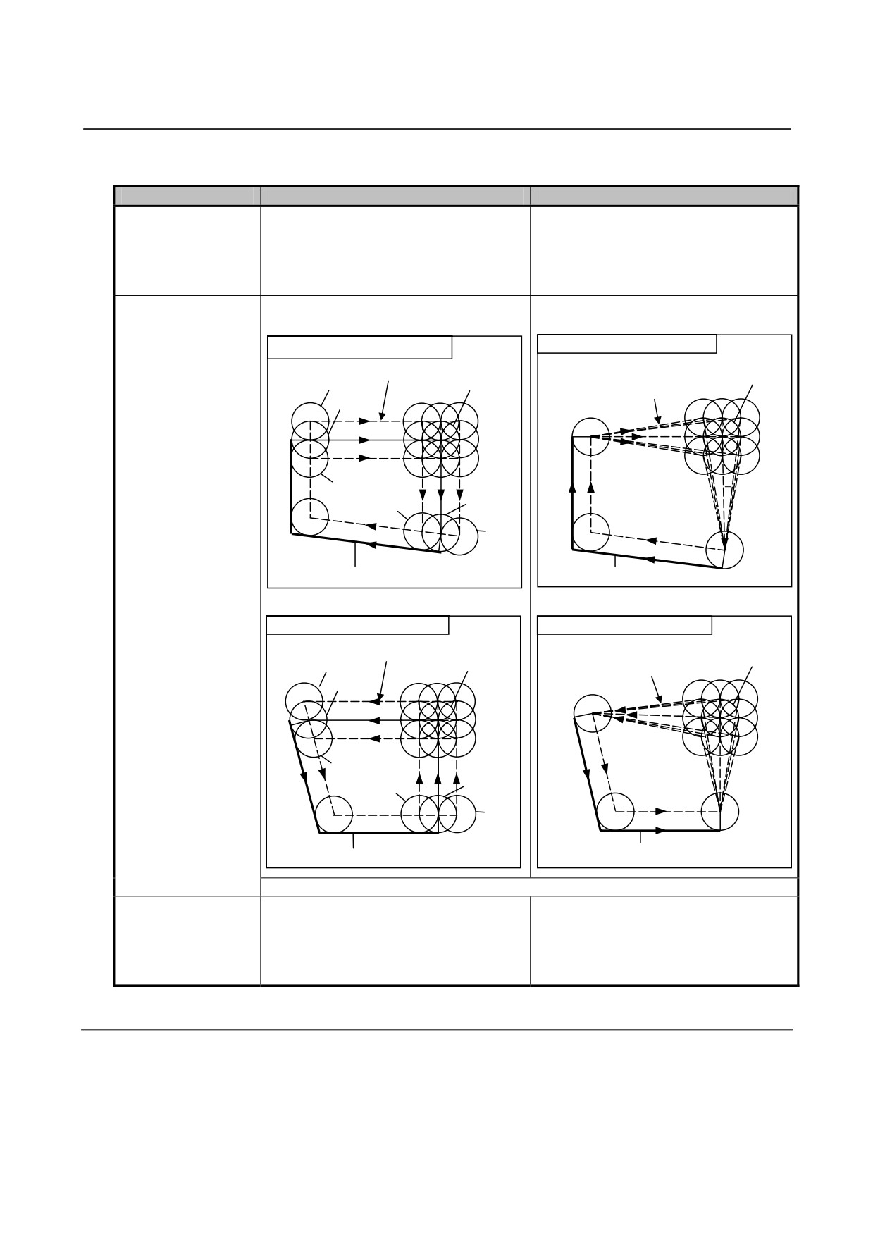
(The numbers in the figure represent
next pocket.
canned cycle for
the tool path sequence.)
(The numbers in the figure represent
turning II)
the tool path sequence.)
Limitation on the
-
Up to 10 pockets can be specified.
-
Not limited.
number of pockets in
Specifying 11 or more pockets causes
G71/G72 type II
alarm PS0068.
(multiple respective
canned cycle for
turning II)
Number of divisions in
-
The number of divisions is also 2 for the
-
The number of divisions specified by R
G73
R1 command. For R2 and subsequent
applies.
commands, the number of divisions
specified by R applies.
Differences regarding the Series 10/11 format
Function
Series 0i-C
Series 0i-D
Pocketing path in
-
Depends on bit 2 (P15) of parameter
-
Bit 2 (P15) of parameter No. 5103 is
G71/G72 type II
No. 5103.
not available.
(multiple respective
[When P15 = 0]
The tool completes one pocketing
canned cycle for
The tool moves from one pocket to
process before proceeding to cut the
turning II)
another for each cut.
next pocket.
(The numbers in the figure represent
(The numbers in the figure represent
the tool path sequence.)
the tool path sequence.)
[When P15 = 1]
The tool completes one pocketing
process before proceeding to cut the
next pocket.
(See the figure at right.)
Limitation on the
-
Depends on bit 2 (P15) of parameter
-
Bit 2 (P15) of parameter No. 5103 is
number of pockets in
No. 5103.
not available.
G71/G72 type II
[When P15 = 0]
Not limited.
(multiple respective
Up to 10 pockets can be specified.
canned cycle for
Specifying 11 or more pockets causes
turning II)
alarm PS0068.
[When P15 = 1]
Not limited.
- 535 -

B.DIFFERENCES FROM SERIES 0i-C APPENDIX
B-64304EN-1/01
Function
Series 0i-C
Series 0i-D
Specification of
-
Not allowed.
-
Allowed.
finishing allowance in
The finishing allowance is ignored if
G71/G72
specified.
Number of divisions in
-
The number of divisions is also 2 for the
-
The number of divisions specified by D
G73
D1 command. For D2 and subsequent
applies.
commands, the number of divisions
specified by D applies.
Address E command
-
Threading is performed as the lead
-
Inch threading is performed.
in G76
threading command of address F.
B.49.2 Differences in Diagnosis Display
None.
- 536 -

B-64304EN-1/01
APPENDIX B.DIFFERENCES FROM SERIES 0i-C
B.50 CHAMFERING AND CORNER ROUNDING
B.50.1 Differences in Specifications
Function
Series 0i-C
Series 0i-D
Chamfering and
-
Not available.
-
Available.
corner rounding
Alarm PS0212 is issued.
The commands can be specified for
commands for a plane
any plane, even one that includes a
other than the Z-X
parallel axis.
plane
Single block operation
-
[Chamfering]
-
[Common to chamfering and corner
Single block stop is not performed at
rounding]
the start point of an inserted chamfering
Whether to perform single block stop at
block.
the start point of an inserted block
[Corner rounding]
depends on bit 0 (SBC) of parameter
Single block stop is performed at the
No. 5105.
start point of an inserted corner
rounding block.
Bit 0 (SBC) of parameter No. 5105
In a drilling canned cycle, chamfer
cycle/corner rounding (T series) or optional
angle chamfering/corner rounding cycle (M
series):
0: Single block stop is not performed.
1: Single block stop is performed.
B.50.2 Differences in Diagnosis Display
None.
- 537 -

B.DIFFERENCES FROM SERIES 0i-C APPENDIX
B-64304EN-1/01
B.51 DIRECT DRAWING DIMENSIONS PROGRAMMING
B.51.1 Differences in Specifications
Function
Series 0i-C
Series 0i-D
Specification of the
-
P/S alarm No. 212 is issued.
-
No alarm is issued.
direct drawing
The command can be specified for a
dimension
plane other than the Z-X plane.
programming
command for a plane
other than the Z-X
plane
When two or more
-
No alarm is issued.
-
Alarm PS0312 is issued.
blocks not to be
moved exist between
consecutive
commands that
specify direct input of
drawing dimensions
B.51.2 Differences in Diagnosis Display
None.
- 538 -