FANUC Series 0i-MODEL D, Series 0i Mate-MODEL D. For Lathe System USER’S MANUAL - page 2
1.GENERAL
PROGRAMMING
B-64304EN-1/01
1.1
OFFSET
Explanation
- Tool offset
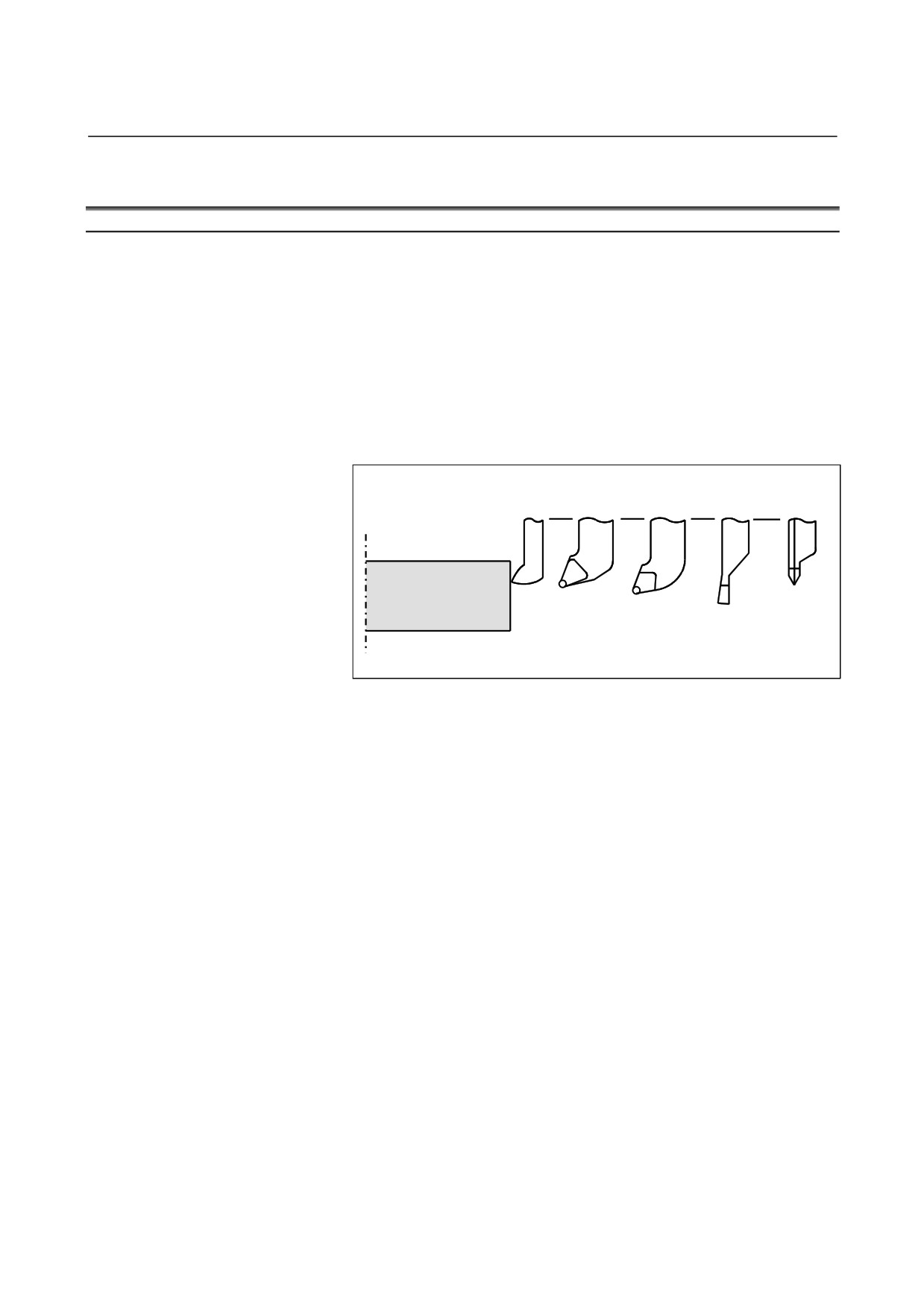
Usually, several tools are used for machining one workpiece. The
tools have different tool length. It is very troublesome to change the
program in accordance with the tools.
Therefore, the length of each tool used should be measured in advance.
By setting the difference between the length of the standard tool and
the length of each tool in the CNC (see “Setting and Displaying Data”
in the User’s Manual (Common to Lathe System/Machining Center
System)), machining can be performed without altering the program
even when the tool is changed. This function is called tool offset.
Standard Rough
Finishing Grooving Threading
tool
cutting
tool
tool
tool
tool
Workpiece
Fig. 1.1 (a) Tool offset
- 14 -
2.PREPARATORY FUNCTION
B-64304EN-1/01
PROGRAMMING
(G FUNCTION)
2
PREPARATORY FUNCTION
(G FUNCTION)
A number following address G determines the meaning of the
command for the concerned block.
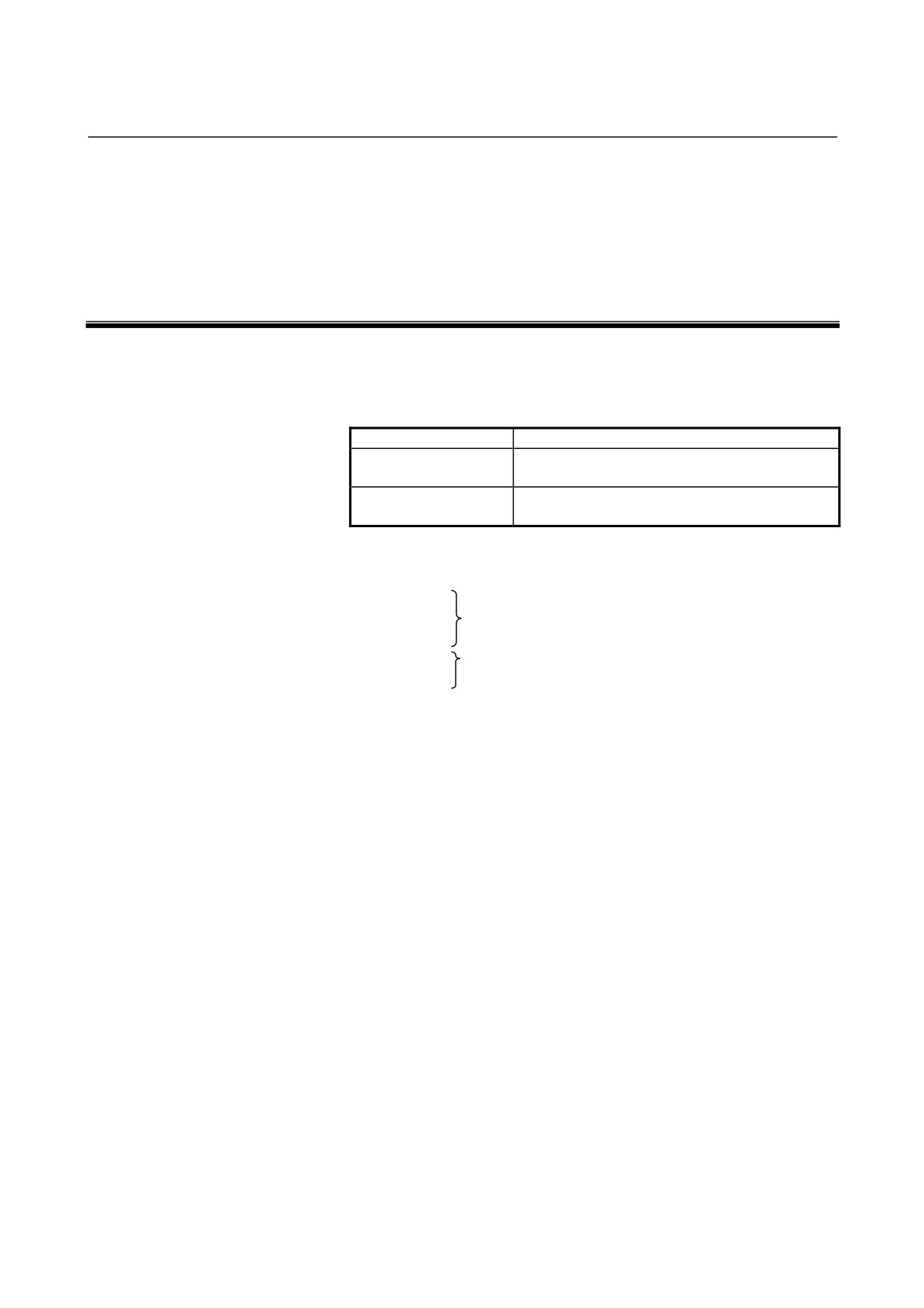
G codes are divided into the following two types.
Type
Meaning
The G code is effective only in the block in which it
One-shot G code
is specified.
The G code is effective until another G code of the
Modal G code
same group is specified.
(Example)
G01 and G00 are modal G codes in group 01.
G01 X_ ;
Z_ ;
G01 is effective in this range.
X_ ;
G00 Z_ ; G00 is effective in this range.
X_ ;
G01 X_ ;
:
There are three G code systems in the lathe system : A,B, and C
(Table 2(a)). Select a G code system using bits 6 (GSB) and 7 (GSC)
parameter No. 3401. Generally, User’s Manual describes the use of G
code system A, except when the described item can use only G code
system B or C. In such cases, the use of G code system B or C is
described.
- 15 -
2. PREPARATORY FUNCTION
(G FUNCTION)
PROGRAMMING
B-64304EN-1/01
Explanation
1.
When the clear state (parameter CLR (No. 3402#6)) is set at
power-up or reset, the modal G codes are placed in the states
described below.
(1) The modal G codes are placed in the states marked with
as indicated in Table 2.
(2) G20 and G21 remain unchanged when the clear state is set
at power-up or reset.
(3) Which status G22 or G23 at power on is set by parameter
G23
(No.
3402#7). However, G22 and G23 remain
unchanged when the clear state is set at reset.
(4) The user can select G00 or G01 by setting parameter G01
(No. 3402#0).
(5) The user can select G90 or G91 by setting parameter G91
(No. 3402#3).
When G code system B or C is used in the lathe system,
setting parameter G91 (No. 3402#3) determines which code,
either G90 or G91, is effective.
2.
G codes in group 00 other than G10 and G11 are one-shot G
codes.
3.
When a G code not listed in the G code list is specified, or a G
code that has no corresponding option is specified, alarm PS0010
occurs.
4.
Multiple G codes can be specified in the same block if each G
code belongs to a different group. If multiple G codes that belong
to the same group are specified in the same block, only the last G
code specified is valid.
5.
If a G code belonging to group 01 is specified in a for drilling,
the canned cycle for drilling is cancelled. This means that the
same state set by specifying G80 is set. Note that the G codes in
group 01 are not affected by a G code specifying a canned cycle.
6.
When G code system A is used, absolute or incremental
programming is specified not by a G code (G90/G91) but by an
address word (X/U, Z/W, C/H, Y/V). Only the initial level is
provided at the return point of the canned cycle for drilling..
7.
G codes are indicated by group.
- 16 -
2.PREPARATORY FUNCTION
B-64304EN-1/01
PROGRAMMING
(G FUNCTION)
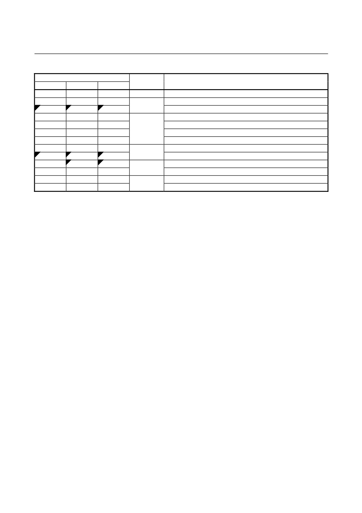
Table 2 G code list
G code system
Group
Function
A
B
C
G00
G00
G00
Positioning (Rapid traverse)
G01
G01
G01
Linear interpolation (Cutting feed)
01
G02
G02
G02
Circular interpolation CW or helical interpolation CW
G03
G03
G03
Circular interpolation CCW or helical interpolation CCW
G04
G04
G04
Dwell
G05.4
G05.4
G05.4
HRV3 on/off
G07.1
G07.1
G07.1
Cylindrical interpolation
(G107)
(G107)
(G107)
00
G08
G08
G08
Advanced preview control
G09
G09
G09
Exact stop
G10
G10
G10
Programmable data input
G11
G11
G11
Programmable data input mode cancel
G12.1
G12.1
G12.1
Polar coordinate interpolation mode
(G112)
(G112)
(G112)
21
G13.1
G13.1
G13.1
Polar coordinate interpolation cancel mode
(G113)
(G113)
(G113)
G17
G17
G17
XpYp plane selection
G18
G18
G18
16
ZpXp plane selection
G19
G19
G19
YpZp plane selection
G20
G20
G70
Input in inch
06
G21
G21
G71
Input in mm
G22
G22
G22
Stored stroke check function on
09
G23
G23
G23
Stored stroke check function off
G25
G25
G25
Spindle speed fluctuation detection off
08
G26
G26
G26
Spindle speed fluctuation detection on
G27
G27
G27
Reference position return check
G28
G28
G28
Return to reference position
00
G30
G30
G30
2nd, 3rd and 4th reference position return
G31
G31
G31
Skip function
G32
G33
G33
Threading
G34
G34
G34
Variable lead threading
G36
G36
G36
01
Automatic tool offset (X axis)
G37
G37
G37
Automatic tool offset (Z axis)
G39
G39
G39
Tool nose radius compensation: corner rounding interpolation
G40
G40
G40
Tool nose radius compensation : cancel
G41
G41
G41
07
Tool nose radius compensation : left
G42
G42
G42
Tool nose radius compensation : right
G50
G92
G92
Coordinate system setting or max spindle speed clamp
00
G50.3
G92.1
G92.1
Workpiece coordinate system preset
G50.2
G50.2
G50.2
Polygon turning cancel
(G250)
(G250)
(G250)
20
G51.2
G51.2
G51.2
Polygon turning
(G251)
(G251)
(G251)
- 17 -
2. PREPARATORY FUNCTION
(G FUNCTION)
PROGRAMMING
B-64304EN-1/01
Table 2 G code list
G code system
Group
Function
A
B
C
G50.4
G50.4
G50.4
Cancel synchronous control
G50.5
G50.5
G50.5
Cancel composite control
G50.6
G50.6
G50.6
Cancel superimposed control
G51.4
G51.4
G51.4
Start synchronous control
00
G51.5
G51.5
G51.5
Start composite control
G51.6
G51.6
G51.6
Start superimposed control
G52
G52
G52
Local coordinate system setting
G53
G53
G53
Machine coordinate system setting
G54
G54
G54
Workpiece coordinate system 1 selection
G55
G55
G55
Workpiece coordinate system 2 selection
G56
G56
G56
Workpiece coordinate system 3 selection
14
G57
G57
G57
Workpiece coordinate system 4 selection
G58
G58
G58
Workpiece coordinate system 5 selection
G59
G59
G59
Workpiece coordinate system 6 selection
G61
G61
G61
Exact stop mode
G63
G63
G63
15
Tapping mode
G64
G64
G64
Cutting mode
G65
G65
G65
00
Macro call
G66
G66
G66
Macro modal call
12
G67
G67
G67
Macro modal call cancel
G68
G68
G68
Mirror image on for double turret or balance cutting mode
04
G69
G69
G69
Mirror image off for double turret or balance cutting mode cancel
G70
G70
G72
Finishing cycle
G71
G71
G73
Stock removal in turning
G72
G72
G74
Stock removal in facing
G73
G73
G75
00
Pattern repeating cycle
G74
G74
G76
End face peck drilling cycle
G75
G75
G77
Outer diameter/internal diameter drilling cycle
G76
G76
G78
Multiple-thread cutting cycle
G71
G71
G72
Traverse grinding cycle (for grinding machine)
G72
G72
G73
Traverse direct sizing/grinding cycle (for grinding machine)
01
G73
G73
G74
Oscillation grinding cycle (for grinding machine)
G74
G74
G75
Oscillation direct sizing/grinding cycle (for grinding machine)
Canned cycle cancel for drilling
G80
G80
G80
Electronic gear box : synchronization cancellation
Spot drilling (FS10/11-T format)
G81
G81
G81
Electronic gear box : synchronization start
G82
G82
G82
10
Counter boring (FS10/11-T format)
G83
G83
G83
Cycle for face drilling
G83.1
G83.1
G83.1
High-speed peck drilling cycle (FS10/11-T format)
G84
G84
G84
Cycle for face tapping
G84.2
G84.2
G84.2
Rigid tapping cycle (FS10/11-T format)
G85
G85
G85
Cycle for face boring
G87
G87
G87
Cycle for side drilling
10
G88
G88
G88
Cycle for side tapping
G89
G89
G89
Cycle for side boring
G90
G77
G20
Outer diameter/internal diameter cutting cycle
G92
G78
G21
01
Threading cycle
G94
G79
G24
End face turning cycle
- 18 -
2.PREPARATORY FUNCTION
B-64304EN-1/01
PROGRAMMING
(G FUNCTION)
Table 2 G code list
G code system
Group
Function
A
B
C
G91.1
G91.1
G91.1
00
Maximum specified incremental amount check
G96
G96
G96
Constant surface speed control
02
G97
G97
G97
Constant surface speed control cancel
G96.1
G96.1
G96.1
Spindle indexing execution (waiting for completion)
G96.2
G96.2
G96.2
Spindle indexing execution (not waiting for completion)
00
G96.3
G96.3
G96.3
Spindle indexing completion check
G96.4
G96.4
G96.4
SV speed control mode ON
G98
G94
G94
Feed per minute
05
G99
G95
G95
Feed per revolution
-
G90
G90
Absolute programming
03
-
G91
G91
Incremental programming
-
G98
G98
Canned cycle : return to initial level
11
-
G99
G99
Canned cycle : return to R point level
- 19 -
3.INTERPOLATION FUNCTION
PROGRAMMING
B-64304EN-1/01
3
INTERPOLATION FUNCTION
Chapter
3, "INTERPOLATION FUNCTION", consists of the
following sections:
3.1 POLAR COORDINATE INTERPOLATION (G12.1, G13.1)...21
3.2 CONSTANT LEAD THREADING (G32)
29
3.3 VARIABLE LEAD THREADING (G34)
33
3.4 CONTINUOUS THREADING
34
3.5 MULTIPLE THREADING
35
- 20 -
B-64304EN-1/01
PROGRAMMING
3.INTERPOLATION FUNCTION
3.1
POLAR COORDINATE INTERPOLATION (G12.1, G13.1)
Overview
Polar coordinate interpolation is a function that exercises contour
control in converting a command programmed in a Cartesian
coordinate system to the movement of a linear axis (movement of a
tool) and the movement of a rotary axis (rotation of a workpiece).
This function is useful in cutting a front surface and grinding a cam
shaft for turning.
Format
G12.1; Starts polar coordinate interpolation mode
(enables polar coordinate interpolation).
Specify linear or circular interpolation using
coordinates in a Cartesian coordinate system
consisting of a linear axis and rotary axis
(hypothetical axis).
G13.1; Polar coordinate interpolation mode is
cancelled (for not performing polar coordinate
interpolation).
Specify G12.1 and G13.1 in Separate Blocks.
G112 and G113 can be used in place of G12.1 and G13.1,
respectively.
Explanation
- Polar coordinate interpolation mode (G12.1)
The axes of polar coordinate interpolation (linear axis and rotary axis)
should be specified in advance, with corresponding parameters.
Specifying G12.1 places the system in the polar coordinate
interpolation mode, and selects a plane (called the polar coordinate
interpolation plane) formed by one linear axis and a hypothetical axis
intersecting the linear axis at right angles. The linear axis is called the
first axis of the plane, and the hypothetical axis is called the second
axis of the plane. Polar coordinate interpolation is performed in this
plane.
In the polar coordinate interpolation mode, both linear interpolation
and circular interpolation can be specified by absolute or incremental
programming.
Tool nose radius compensation can also be performed. The polar
coordinate interpolation is performed for a path obtained after tool
nose radius compensation.
The tangential velocity in the polar coordinate interpolation plane
(Cartesian coordinate system) is specified as the feedrate, using F.
- Polar coordinate interpolation cancel mode (G13.1)
Specifying G13.1 cancels the polar coordinate interpolation mode.
- 21 -
3.INTERPOLATION FUNCTION
PROGRAMMING
B-64304EN-1/01
- Polar coordinate interpolation plane
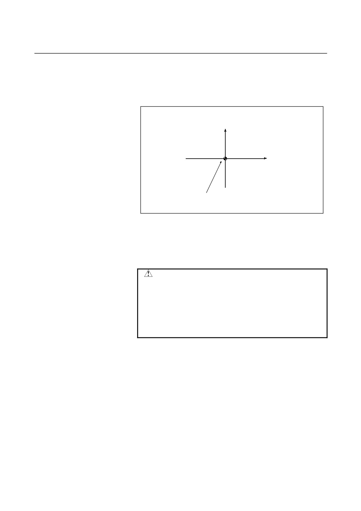
G12.1 starts the polar coordinate interpolation mode and selects a
polar coordinate interpolation plane (Fig. 3.1 (a)). Polar coordinate
interpolation is performed on this plane.
Rotary axis (hypothetical axis)
(unit: mm or inch)
Linear axis
(unit: mm or inch)
Origin of the local coordinate system (G52 command)
(Or origin of the workpiece coordinate system)
Fig. 3.1 (a) Polar coordinate interpolation plane
When the power is turned on or the system is reset, polar coordinate
interpolation is canceled (G13.1).
The linear and rotation axes for polar coordinate interpolation must be
set in parameters Nos. 5460 and 5461 beforehand.
CAUTION
The plane used before G12.1 is specified (plane
selected by G17, G18, or G19) is canceled. It is
restored when G13.1 (canceling polar coordinate
interpolation) is specified.
When the system is reset, polar coordinate
interpolation is canceled and the plane specified by
G17, G18, or G19 is used.
- Distance moved and feedrate for polar coordinate interpolation
•
The unit for coordinates on the hypothetical axis is the same as
the unit for the linear axis (mm/inch).
In the polar coordinate interpolation mode, program commands
are specified with Cartesian coordinates on the polar coordinate
interpolation plane. The axis address for the rotary axis is used as
the axis address for the second axis (hypothetical axis) in the
plane. Whether a diameter or radius is specified for the first axis
in the plane is the same as for the rotary axis regardless of the
specification for the first axis in the plane.
The hypothetical axis is at coordinate 0 immediately after G12.1
is specified. Polar interpolation is started assuming the rotation
angle of 0 for the position of the tool when G12.1 is specified.
- 22 -
B-64304EN-1/01
PROGRAMMING
3.INTERPOLATION FUNCTION
Example)
When a value on the X-axis
(linear axis) is input in
millimeters
G12.1;
G01 X10. F1000. ; ..A 10-mm movement is made on the
Cartesian coordinate system.
C20. ;
A 20-mm movement is made on the
Cartesian coordinate system.
G13.1;
When a value on the X-axis (linear axis) is input in inches
G12.1;
G01 X10. F1000. ;
A 10-inch movement is made on the
Cartesian coordinate system.
C20. ;
A 20-inch movement is made on the
Cartesian coordinate system.
G13.1;
•
The unit for the feedrate is mm/min or inch/min.
Specify the feedrate as a speed
(relative speed between the
workpiece and tool) tangential to the polar coordinate
interpolation plane (Cartesian coordinate system) using F.
- G codes which can be specified in the polar coordinate interpolation mode
G01
Linear interpolation
G02, G03
Circular interpolation
G04
Dwell
G40, G41, G42
Tool nose radius compensation
(Polar coordinate interpolation is applied to the
path after tool nose radius compensation.)
G65, G66, G67
Custom macro command
G90, G91
Absolute programming, incremental programming
(For G code system B or C)
G98, G99
Feed per minute, feed per revolution
- Circular interpolation in the polar coordinate plane
The addresses for specifying the radius of an arc for circular
interpolation (G02 or G03) in the polar coordinate interpolation plane
depend on the first axis in the plane (linear axis).
•
I and J in the Xp-Yp plane when the linear axis is the X-axis or
an axis parallel to the X-axis.
•
J and K in the Yp-Zp plane when the linear axis is the Y-axis or
an axis parallel to the Y-axis.
•
K and I in the Zp-Xp plane when the linear axis is the Z-axis or
an axis parallel to the Z-axis.
The radius of an arc can be specified also with an R command.
NOTE
The parallel axes U, V, and W can be used in the G
code system B or C.
- 23 -
3.INTERPOLATION FUNCTION
PROGRAMMING
B-64304EN-1/01
- Movement along axes not in the polar coordinate interpolation plane in the polar
coordinate interpolation mode
The tool moves along such axes normally, independent of polar
coordinate interpolation.
- Current position display in the polar coordinate interpolation mode
Actual coordinates are displayed. However, the remaining distance to
move in a block is displayed based on the coordinates in the polar
coordinate interpolation plane (Cartesian coordinates).
- Coordinate system for the polar coordinate interpolation
Basically, before G12.1 is specified, a local coordinate system (or
workpiece coordinate system) where the center of the rotary axis is the
origin of the coordinate system must be set.
In the G12.1 mode, the coordinate system must not be changed (G50,
G52, G53, relative coordinate reset, G54 through G59, etc.).
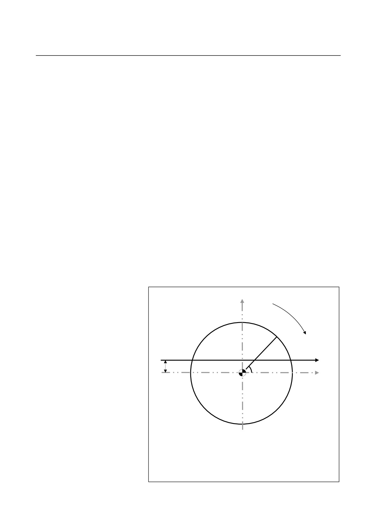
- Compensation in the direction of the hypothetical axis in polar coordinate
interpolation
If the first axis of the plane has an error from the center of the rotary
axis in the hypothetical axis direction, in other words, if the rotary
axis center is not on the X-axis, the hypothetical axis direction
compensation function in the polar coordinate interpolation mode is
used. With the function, the error is considered in polar coordinate
interpolation. The amount of error is specified in parameter No. 5464.
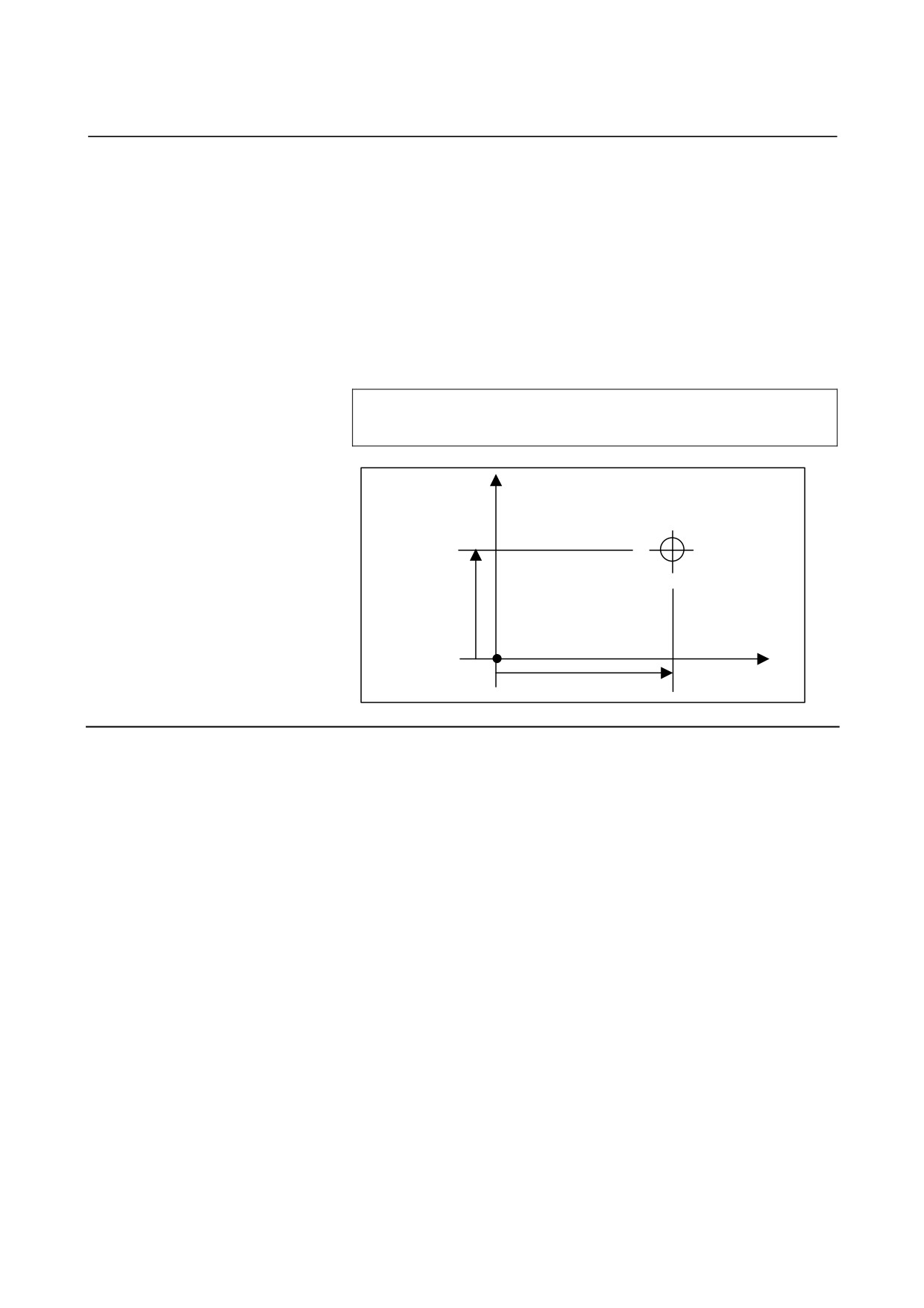
Hypothetical axis (C-axis)
Rotary axis
(X, C)
X-axis
Error in the direction of
hypothetical axis (P)
Center of rotary axis
(X, C)
Point in the X-C plane (The center of the rotary axis is
considered to be the origin of the X-C plane.)
X
X coordinate in the X-C plane
C
Hypothetical axis coordinate in the X-C plane
P
Error in the direction of the hypothetical axis
(specified in parameter No. 5464)
- 24 -
B-64304EN-1/01
PROGRAMMING
3.INTERPOLATION FUNCTION
- Shifting the coordinate system in polar coordinate interpolation
In the polar coordinate interpolation mode, the workpiece coordinate
system can be shifted. The current position display function shows the
position viewed from the workpiece coordinate system before the shift.
The function to shift the coordinate system is enabled when bit 2
(PLS) of parameter No. 5450 is specified accordingly.
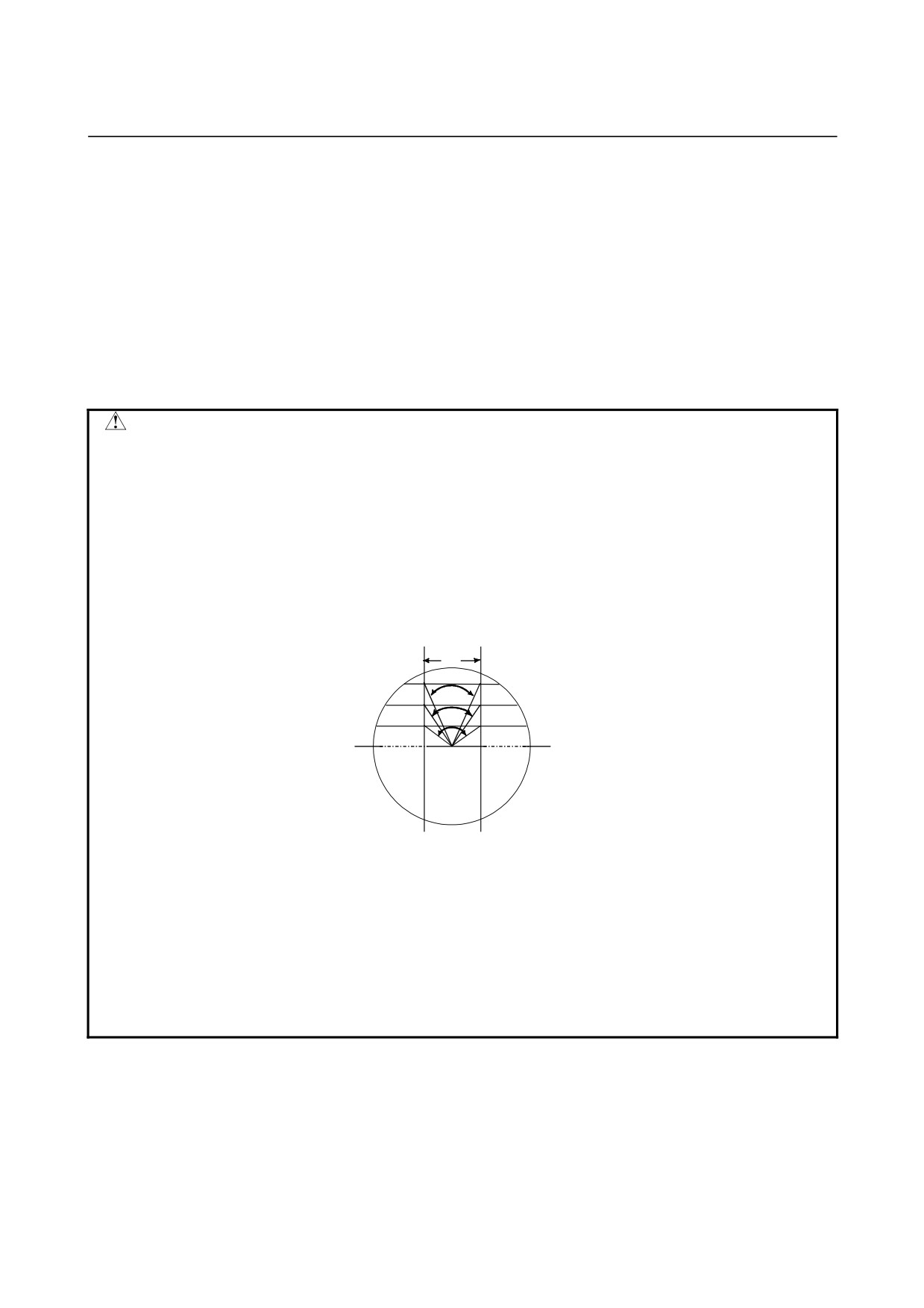
The shift can be specified in the polar coordinate interpolation mode,
by specifying the position of the center of the rotary axis C (A, B) in
the X-C (Y-A, Z-B) interpolation plane with reference to the origin of
the workpiece coordinate system, in the following format.
G12.1 X_ C_ ;
(Polar coordinate interpolation for the X-axis and C-axis)
G12.1 Y_ A_ ;
(Polar coordinate interpolation for the Y-axis and A-axis)
G12.1 Z_ B_ ;
(Polar coordinate interpolation for the Z-axis and B-axis)
C
G12.1 Xx Cc ;
Center of C-axis
c
X
Origin of workpiece
coordinate system
x
Limitation
- Changing the coordinate system during polar coordinate interpolation
In the G12.1 mode, the coordinate system must not be changed (G92,
G52, G53, relative coordinate reset, G54 through G59, etc.).
- Tool nose radius compensation
The polar coordinate interpolation mode (G12.1 or G13.1) cannot be
started or terminated in the tool nose radius compensation mode (G41
or G42). G12.1 or G13.1 must be specified in the tool nose radius
compensation canceled mode (G40).
- Tool offset command
A tool offset must be specified before the G12.1 mode is set. No offset
can be changed in the G12.1 mode.
- Program restart
For a block in the G12.1 mode, the program cannot be restarted.
- 25 -
3.INTERPOLATION FUNCTION
PROGRAMMING
B-64304EN-1/01
- Cutting feedrate for the rotary axis
Polar coordinate interpolation converts the tool movement for a figure
programmed in a Cartesian coordinate system to the tool movement in
the rotary axis (C-axis) and the linear axis (X-axis). When the tool
comes close to the center of the workpiece, the C-axis velocity
component increases. If the maximum cutting feedrate for the C-axis
(parameter No. 1430) is exceeded, the automatic feedrate override
function and automatic speed clamp function are enabled.
If the maximum cutting feedrate for the X-axis is exceeded, the
automatic feedrate override function and automatic speed clamp
function are enabled.
WARNING
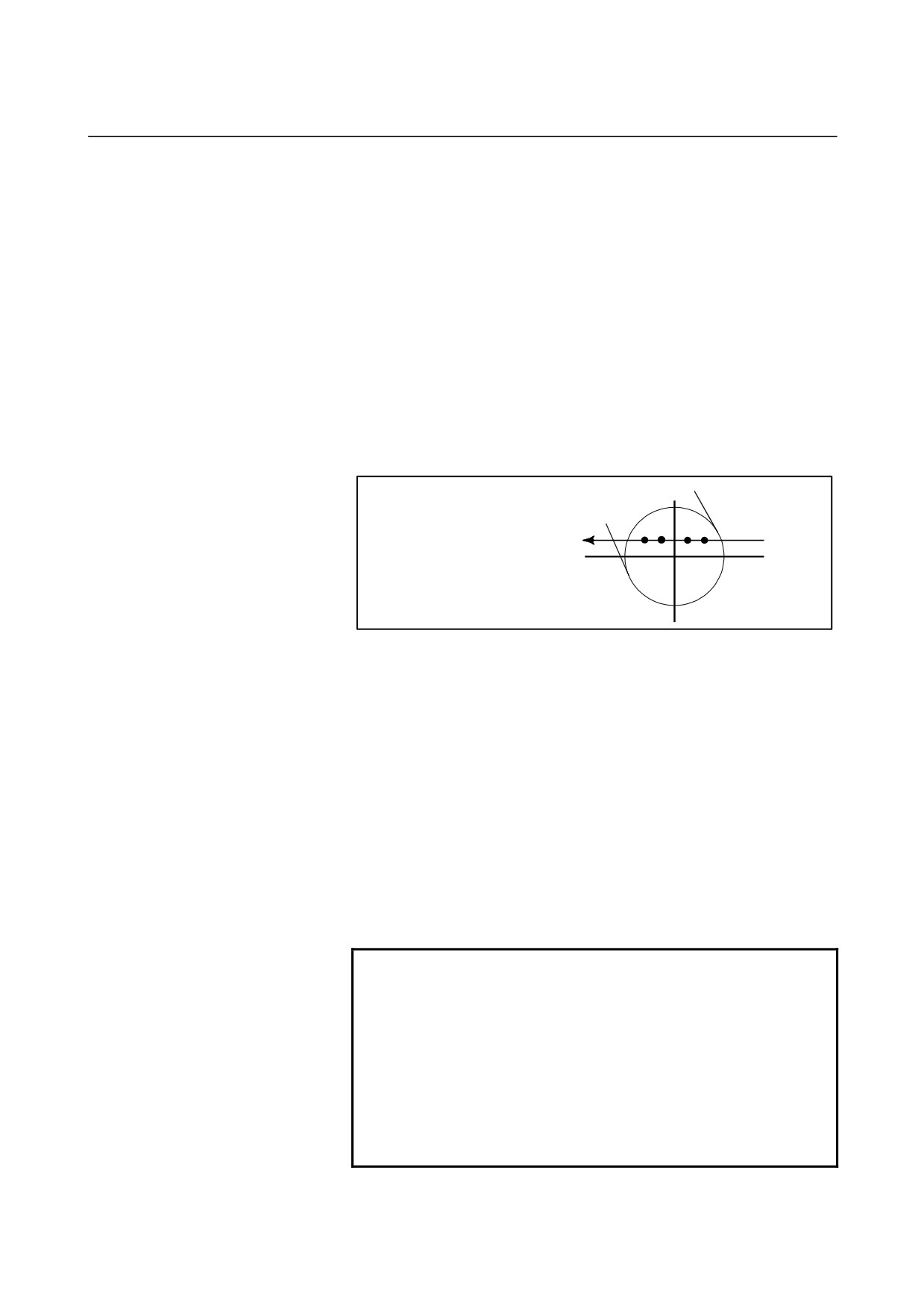
Consider lines L1, L2, and L3. ∆X is the distance the tool moves per time unit at the
feedrate specified with address F in the Cartesian coordinate system. As the tool
moves from L1 to L2 to L3, the angle at which the tool moves per time unit
corresponding to ∆X in the Cartesian coordinate system increases from θ1 to θ2 to
θ3. In other words, the C-axis component of the feedrate becomes larger as the
tool moves closer to the center of the workpiece. The C component of the feedrate
may exceed the maximum cutting feedrate for the C-axis because the tool
movement in the Cartesian coordinate system has been converted to the tool
movement for the C-axis and the X-axis.
∆X
θ1
L1
θ2
L2
θ3
L3
L: Distance (in mm) between the tool center and workpiece center when the tool
center is the nearest to the workpiece center
R: Maximum cutting feedrate (deg/min) of the C axis
Then, a speed specifiable with address F in polar coordinate interpolation can be
given by the formula below. If the maximum cutting feedrate for the C-axis is
exceeded, the automatic speed control function for polar coordinate interpolation
automatically controls the feedrate.
F < L × R × π
(mm/min)
180
- Automatic speed control for polar coordinate interpolation
If the velocity component of the rotary axis exceeds the maximum
cutting feedrate in the polar coordinate interpolation mode, the speed
is automatically controlled.
- 26 -
B-64304EN-1/01
PROGRAMMING
3.INTERPOLATION FUNCTION
- Automatic override
If the velocity component of the rotary axis exceeds the permissible
velocity
(maximum cutting feedrate multiplied by the permission
factor specified in parameter No. 5463), the feedrate is automatically
overridden as indicated below.
Override = (Permissible velocity) ÷ (Velocity component of rotary
axis) × 100(%)
- Automatic speed clamp
If the velocity component of the rotary axis after automatic override
still exceeds the maximum cutting feedrate, the speed of the rotary
axis is automatically clamped. As a result, the velocity component of
the rotary axis will not exceed the maximum cutting feedrate.
The automatic speed clamp function works only when the center of
the tool is very close to the center of the rotary axis.
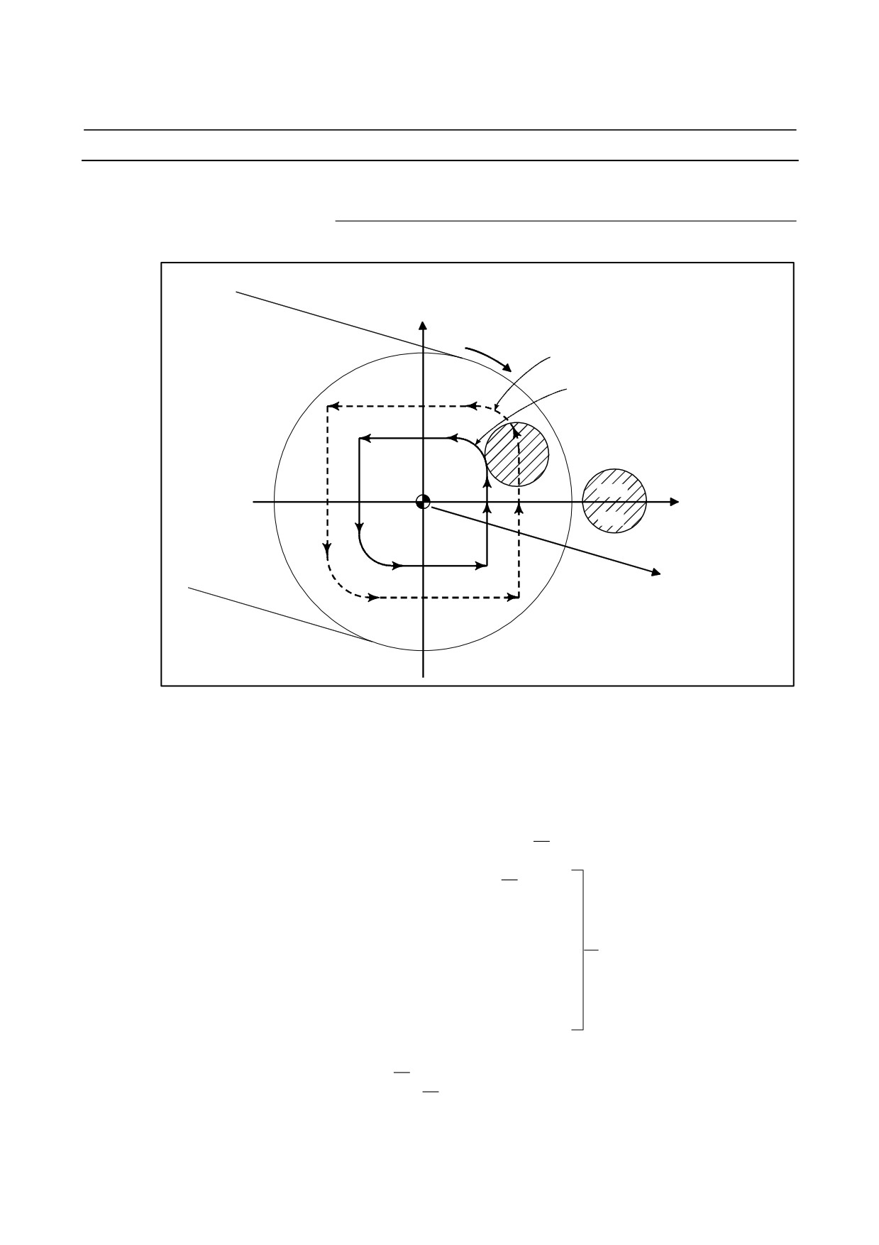
C-axis
[Example]
G90 G00 X10.0 C0. ;
D C
B A
G12.1 ;
G01 C0.1 F1000 ;
X-axis
-10.
+10.
X-10.0 :
G13.1 ;
Automatic speed control for polar coordinate interpolation
Suppose that the maximum cutting feedrate of the rotary axis is 360
(3600 deg/min) and that the permission factor of automatic override
for polar coordinate interpolation (parameter No. 5463) is 0 (90%).
If the program indicated above is executed, the automatic override
function starts working when the X coordinate becomes 2.273 (point
A). The automatic speed clamp function starts working when the X
coordinate becomes 0.524 (point B).
The minimum value of automatic override for this example is 3%.
The automatic speed clamp function continues working until the X
coordinate becomes -0.524 (point C). Then, the automatic override
function works until the X coordinate becomes -2.273 (point D).
(The coordinates indicated above are the values in the Cartesian
coordinate system.)
NOTE
1 While the automatic speed clamp function is
working, the machine lock or interlock function may
not be enabled immediately.
2 If a feed hold stop is made while the automatic
speed clamp function is working, the automatic
operation halt signal is output. However, the
operation may not stop immediately.
3 The clamped speed may exceed the clamp value
by a few percent.
- 27 -
3.INTERPOLATION FUNCTION
PROGRAMMING
B-64304EN-1/01
Example
Sample program for polar coordinate interpolation in a Cartesian
coordinate system consisting of the X-axis
(a linear axis) and a
hypothetical axis
Hypothetical axis
C axis
Path after tool nose radius compensation
Path before tool nose radius compensation
N204
N203
N205
N202
N201
N200
X axis
Tool
N208
N206
N207
Z axis
The X-axis is by diameter programming; the C-axis is by radius
programming.
O0001 ;
:
N010 T0101 ;
:
N0100 G90 G00 X120.0 C0 Z
Positioning to start point
N0200 G12.1 ;
Start of polar coordinate interpolation
N0201 G42 G01 X40.0 F
;
N0202 C10.0 ;
N0203 G03 X20.0 C20.0 R10.0 ;
Geometry program
N0204 G01 X-40.0 ;
(program based on Cartesian
N0205 C-10.0 ;
coordinates on the plane of the
N0206 G03 X-20.0 C-20.0 I10.0 J0 ;
X-axis and virtual axis)
N0207 G01 X40.0 ;
N0208 C0 ;
N0209 G40 X120.0 ;
N0210 G13.1 ;
Cancellation of polar coordinate
N0300 Z
;
interpolation
N0400 X C
;
:
N0900 M30 ;
- 28 -
B-64304EN-1/01
PROGRAMMING
3.INTERPOLATION FUNCTION
3.2
CONSTANT LEAD THREADING (G32)
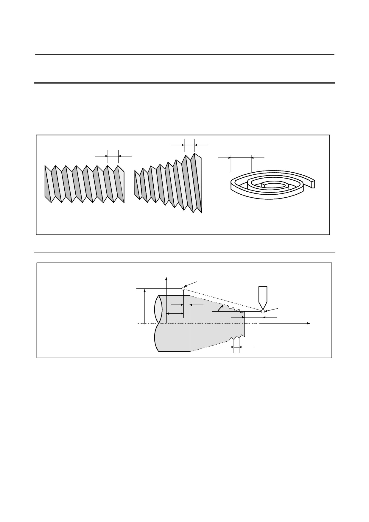
Tapered screws and scroll threads in addition to equal lead straight
threads can be cut by using a G32 command.
The spindle speed is read from the position coder on the spindle in
real time and converted to a cutting feedrate for feed-per minute mode,
which is used to move the tool.
L
L
L
Straight thread
Tapered screw
Scroll thread
Fig. 3.2 (a) Thread types
Format
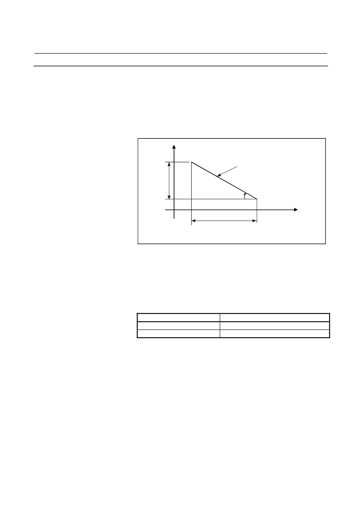
G32IP_F_;
X axis
End point_
IP_: End point
F _: Lead of the long axis
(always radius programming)
δ2
X
α
Start point
Z
δ1
Z axis
0
L
Fig. 3.2 (b) Example of threading
- 29 -
3.INTERPOLATION FUNCTION
PROGRAMMING
B-64304EN-1/01
Explanation
In general, threading is repeated along the same tool path in rough
cutting through finish cutting for a screw. Since threading starts when
the position coder mounted on the spindle outputs a
one-spindle-rotation signal, threading is started at a fixed point and the
tool path on the workpiece is unchanged for repeated threading. Note
that the spindle speed must remain constant from rough cutting
through finish cutting. If not, incorrect thread lead will occur.
X
Tapered thread
LX
α
Z
LZ
α≤45° lead is LZ
α≥45° lead is LX
Fig. 3.2 (c) LZ and LX of a tapered thread
In general, the lag of the servo system, etc. will produce somewhat
incorrect leads at the starting and ending points of a thread cut. To
compensate for this, a threading length somewhat longer than required
should be specified.
Table 3.2 (a) lists the ranges for specifying the thread lead.
Table 3.2 (a) Ranges of lead sizes that can be specified
Least command increment
Metric input
0.0001 to 500.0000 mm
Inch input
0.000001 to 9.999999 inch
- 30 -
B-64304EN-1/01
PROGRAMMING
3.INTERPOLATION FUNCTION
Example
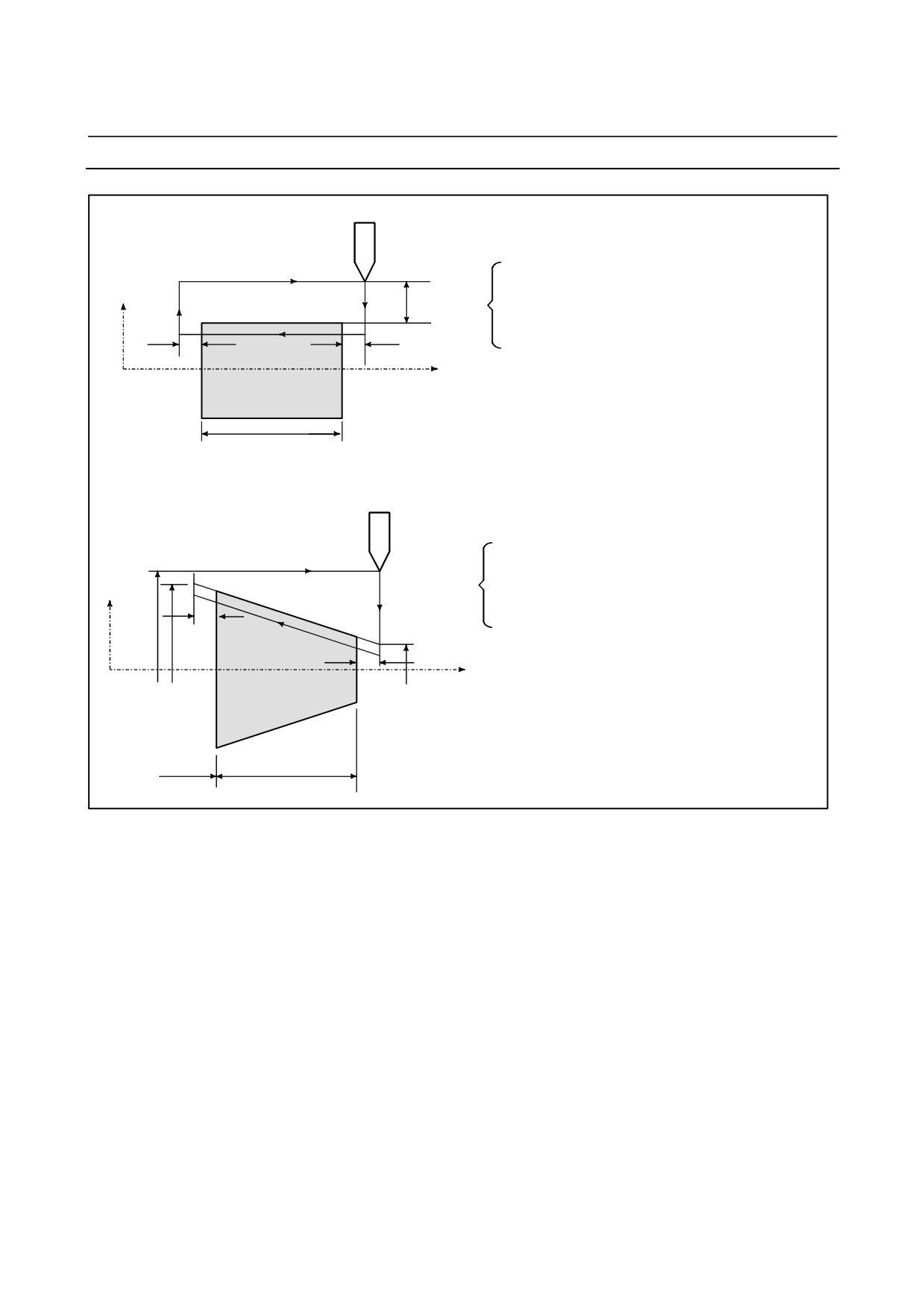
1. Straight threading
The following values are used in programming :
Thread lead :4mm
X axis
30mm
δ1=3mm
δ2=1.5mm
Depth of cut :1mm (cut twice)
(Metric input, diameter programming)
δ2
δ1
G00 U-62.0 ;
Z axis
G32 W-74.5 F4.0 ;
G00 U62.0
;
W74.5
;
U-64.0 ;
(For the second cut, cut 1mm more)
70
G32 W-74.5
;
G00 U64.0
;
W74.5
;
2.Tapered threading
The following values are used in programming :
Thread lead : 3.5mm in the direction of the Z axis
δ1=2mm
X axis
δ2=1mm
Cutting depth in the X axis direction is 1mm (cut twice)
φ50
δ2
(Metric input, diameter programming)
G00 X 12.0 Z72.0 ;
φ43
G32 X 41.0 Z29.0 F3.5 ;
δ1
G00 X 50.0 ;
Z 72.0 ;
0
Z axis
X 10.0 ;
φ14
(Cut 1mm more for the second cut)
G32 X 39.0 Z29.0
;
G00 X 50.0
;
Z 72.0
;
30
40
- 31 -
3.INTERPOLATION FUNCTION
PROGRAMMING
B-64304EN-1/01
WARNING
1
Feedrate override is effective (fixed at 100%) during threading.
2
It is very dangerous to stop feeding the thread cutter without stopping the spindle.
This will suddenly increase the cutting depth. Thus, the feed hold function is
ineffective while threading. If the feed hold button is pressed during threading, the
tool will stop after a block not specifying threading is executed as if the SINGLE
BLOCK button were pushed. However, the feed hold lamp (SPL lamp) lights when
the FEED HOLD button on the machine control panel is pushed. Then, when the
tool stops, the lamp is turned off (Single Block stop status).
3
When the FEED HOLD button is pressed again in the first block after threading
mode that does not specify threading (or the button has been held down), the tool
stops immediately at the block that does not specify threading.
4
When threading is executed in the single block status, the tool stops after execution
of the first block not specifying threading.
5
When the mode was changed from automatic operation to manual operation during
threading, the tool stops at the first block not specifying threading as when the feed
hold button is pushed as mentioned in Warning 3.
However, when the mode is changed from one automatic operation mode to
another, the tool stops after execution of the block not specifying threading as for
the single block mode in Note 4.
6
When the previous block was a threading block, cutting will start immediately
without waiting for detection of the one-spindle-rotation signal even if the present
block is a threading block.
G32Z _ F_ ;
Z _;
(A 1-turn signal is not detected before this block.)
G32 ;
(Regarded as threading block.)
Z_ F_ ; (One turn signal is also not detected.)
7
Because the constant surface speed control is effective during scroll thread or
tapered screw cutting and the spindle speed changes, the correct thread lead may
not be cut. Therefore, do not use the constant surface speed control during
threading. Instead, use G97.
8
A movement block preceding the threading block must not specify chamfering or
corner R.
9
A threading block must not specifying chamfering or corner R.
10 The spindle speed override function is disabled during threading. The spindle
speed is fixed at 100%.
11 Thread cycle retract function is ineffective to G32.
- 32 -
B-64304EN-1/01
PROGRAMMING
3.INTERPOLATION FUNCTION
3.3
VARIABLE LEAD THREADING (G34)
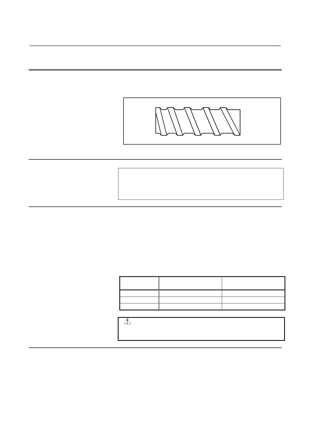
Specifying an increment or a decrement value for a lead per screw
revolution enables variable lead threading to be performed.
Fig. 3.3 (a) Variable lead screw
Format
G34 IP_ F_ K_ ;
IP_ : End point
F_
: Lead in longitudinal axis direction at the start point
K_ : Increment and decrement of lead per spindle revolution
Explanation
Address other than K are the same as in straight/taper thread cutting
with G32.
The K value depends on the increment system of the reference axis, as
indicated in Table 3.3 (a).
If the specified K value exceeds the range indicated in Table 3.3 (a), if
the maximum lead is exceeded after a change due to the K value, or if
the lead value is negative, an alarm PS0313 will be issued.
Table 3.3 (a) Range of valid K values
Increment system
Metric input (mm/rev)
Inch input (inch/rev)
of reference axis
IS-A
±0.001
to
±500.000
±0.00001
to ±50.00000
IS-B
±0.0001
to
±500.0000
±0.000001 to ±50.000000
IS-C
±0.00001
to
±50.00000
±0.0000001 to
±5.0000000
CAUTION
The "thread cutting cycle retract" is not effective for
G34.
Example
Lead at the start point: 8.0 mm
Lead increment: 0.3 mm/rev
G34 Z-72.0 F8.0 K0.3 ;
- 33 -

3.INTERPOLATION FUNCTION
PROGRAMMING
B-64304EN-1/01
3.4
CONTINUOUS THREADING
Threading blocks can be programmed successively to eliminate a
discontinuity due to a discontinuous movement in machining by
adjacent blocks.
Explanation
Since the system is controlled in such a manner that the synchronism
with the spindle does not deviate in the joint between blocks wherever
possible, it is possible to performed special threading operation in
which the lead and shape change midway.
G32
G32
G32
Fig. 3.4 (a) Continuous threading (Example of G32 in G code system A)
Even when the same section is repeated for threading while changing
the depth of cut, this system allows a correct machining without
impairing the threads.
- 34 -
B-64304EN-1/01
PROGRAMMING
3.INTERPOLATION FUNCTION
3.5
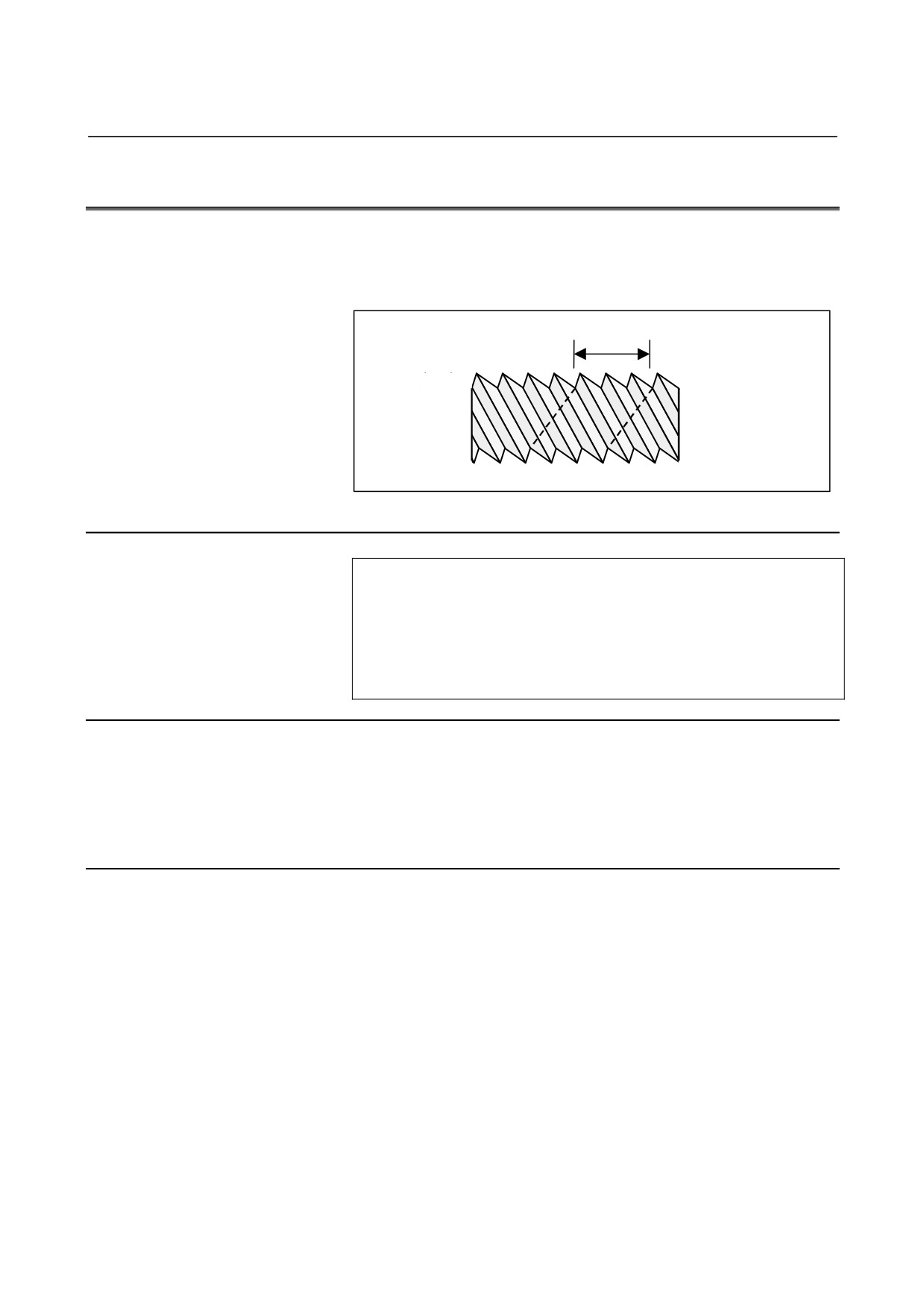
MULTIPLE THREADING
Using the Q address to specify an angle between the
one-spindle-rotation signal and the start of threading shifts the
threading start angle, making it possible to produce multiple-thread
screws with ease.
L
L : Lead
Fig. 3.5 (a) Multiple thread screws.
Format
(Constant lead threading)
G32 IP _ F_ Q_ ;
IP : End point
F_ : Lead in longitudinal direction
G32 IP _ Q_ ;
Q_ : Threading start angle
Explanation
- Available threading commands
G32: Constant lead threading
G34: Variable lead threading
G76: Multiple threading cycle
G92: Threading cycle
Limitation
- Start angle
The start angle is not a continuous state (modal) value. It must be
specified each time it is used. If a value is not specified, 0 is assumed.
- Start angle increment
The start angle (Q) increment is 0.001 degrees. Note that no decimal
point can be specified.
Example:
For a shift angle of 180 degrees, specify Q180000.
Q180.000 cannot be specified, because it contains a decimal
point.
- 35 -
3.INTERPOLATION FUNCTION
PROGRAMMING
B-64304EN-1/01
- Specifiable start angle range
A start angle (Q) of between 0 and 360000 (in 0.001-degree units) can
be specified. If a value greater than 360000 (360 degrees) is specified,
it is rounded down to 360000 (360 degrees).
- Multiple threading cycle (G76)
For the G76 multiple threading cycle command, always use the
FS10/11 command format.
Example
Program for producing double-threaded screws
(with start angles of 0 and 180 degrees)
G00 X40.0 ;
G32 W-38.0 F4.0 Q0 ;
G00 X72.0 ;
W38.0 ;
X40.0 ;
G32 W-38.0 F4.0Q180000 ;
G00 X72.0 ;
W38.0 ;
- 36 -
4.FUNCTIONS TO SIMPLIFY
B-64304EN-1/01
PROGRAMMING
PROGRAMMING
4
FUNCTIONS TO SIMPLIFY
PROGRAMMING
Chapter
4, "FUNCTIONS TO SIMPLIFY PROGRAMMING",
consists of the following sections:
4.1 CANNED CYCLE (G90, G92, G94)
38
4.2 MULTIPLE REPETITIVE CANNED CYCLE (G70-G76)
59
4.3 CANNED CYCLE FOR DRILLING
99
4.4 RIGID TAPPING
115
4.5 CANNED GRINDING CYCLE
(FOR GRINDING MACHINE)
131
4.6 CHAMFERING AND CORNER R
145
4.7 MIRROR IMAGE FOR DOUBLE TURRET (G68, G69)
153
4.8 DIRECT DRAWING DIMENSION PROGRAMMING
155
- 37 -
4. FUNCTIONS TO SIMPLIFY
PROGRAMMING
PROGRAMMING
B-64304EN-1/01
4.1
CANNED CYCLE (G90, G92, G94)
There are three canned cycles : the outer diameter/internal diameter
cutting canned cycle (G90), the threading canned cycle (G92), and the
end face turning canned cycle (G94).
NOTE
1 Explanatory figures in this section use the ZX plane
as the selected plane, diameter programming for
the X-axis, and radius programming for the Z-axis.
When radius programming is used for the X-axis,
change U/2 to U and X/2 to X.
2 A canned cycle can be performed on any plane
(including parallel axes for plane definition). When
G-code system A is used, however, U, V, and W
cannot be set as a parallel axis.
3 The direction of the length means the direction of
the first axis on the plane as follows:
ZX plane: Z-axis direction
YZ plane: Y-axis direction
XY plane: X-axis direction
4 The direction of the end face means the direction of
the second axis on the plane as follows:
ZX plane: X-axis direction
YZ plane: Z-axis direction
XY plane: Y-axis direction
- 38 -
4.FUNCTIONS TO SIMPLIFY
B-64304EN-1/01
PROGRAMMING
PROGRAMMING
4.1.1
Outer Diameter/Internal Diameter Cutting Cycle (G90)
This cycle performs straight or taper cutting in the direction of the
length.
4.1.1.1
Straight cutting cycle
Format
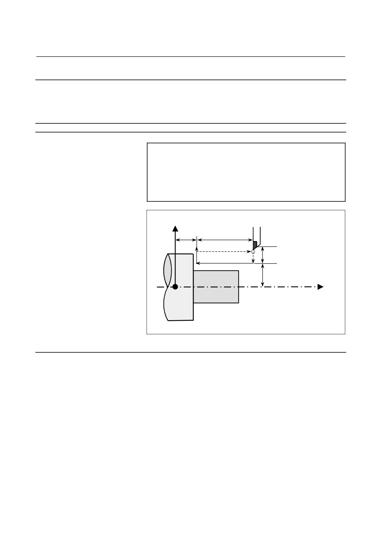
G90X(U)_Z(W)_F_;
X_,Z_ : Coordinates of the cutting end point (point A' in the
figure below) in the direction of the length
U_,W_ : Travel distance to the cutting end point (point A' in
the figure below) in the direction of the length
F_
: Cutting feedrate
X axis
(R)
Rapid traverse
Z
(F)
Cutting feed
W
4(R)
A
3(F)
2(F)
1(R)
U/2
A’
X/2
Z axis
Fig. 4.1.1 (a) Straight cutting cycle
Explanation
- Operations
A straight cutting cycle performs four operations:
(1) Operation
1 moves the tool from the start point
(A) to the
specified coordinate of the second axis on the plane (specified
X-coordinate for the ZX plane) in rapid traverse.
(2) Operation 2 moves the tool to the specified coordinate of the first
axis on the plane (specified Z-coordinate for the ZX plane) in
cutting feed. (The tool is moved to the cutting end point (A') in
the direction of the length.)
(3) Operation 3 moves the tool to the start coordinate of the second
axis on the plane (start X-coordinate for the ZX plane) in cutting
feed.
(4) Operation 4 moves the tool to the start coordinate of the first axis
on the plane
(start Z-coordinate for the ZX plane) in rapid
traverse. (The tool returns to the start point (A).)
- 39 -
4. FUNCTIONS TO SIMPLIFY
PROGRAMMING
PROGRAMMING
B-64304EN-1/01
NOTE
In single block mode, operations 1, 2, 3 and 4 are
performed by pressing the cycle start button once.
- Canceling the mode
To cancel the canned cycle mode, specify a group 01 G code other
than G90, G92, or G94.
- 40 -
4.FUNCTIONS TO SIMPLIFY
B-64304EN-1/01
PROGRAMMING
PROGRAMMING
4.1.1.2
Taper cutting cycle
Format
G90 X(U)_Z(W)_R_F_;
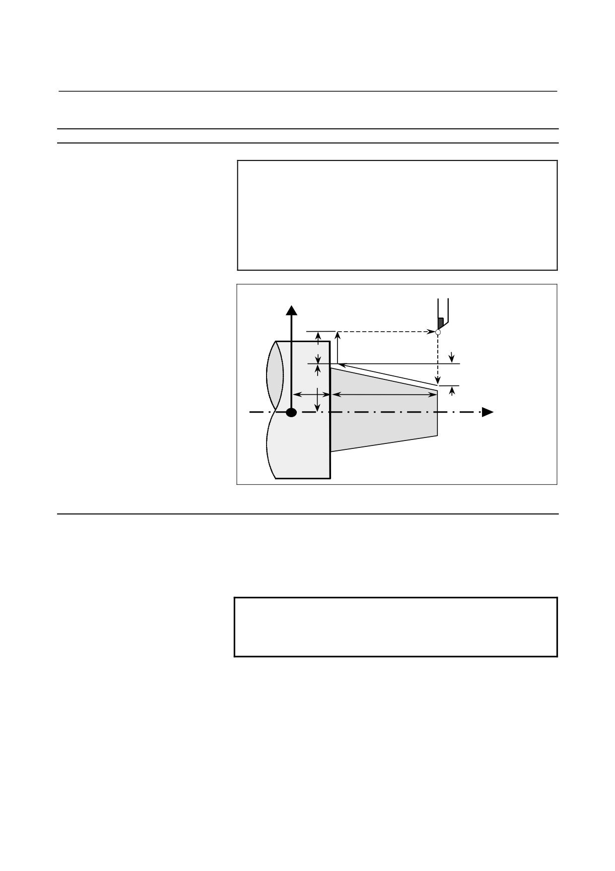
X_,Z_ : Coordinates of the cutting end point (point A' in the
figure below) in the direction of the length
U_,W_ : Travel distance to the cutting end point (point A' in
the figure below) in the direction of the length
R_
: Taper amount (R in the figure below)
F_
: Cutting feedrate
X axis
(R)
Rapid traverse
4
(R)
(F)
Cutting feed
A
3
(F)
U/2
1
(R)
A’
2
(F)
R
X/2
W
Z
Z axis
Fig. 4.1.1 (b) Taper cutting cycle
Explanation
The figure of a taper is determined by the coordinates of the cutting
end point (A') in the direction of the length and the sign of the taper
amount (address R). For the cycle in the figure above, a minus sign is
added to the taper amount.
NOTE
The increment system of address R for specifying a
taper depends on the increment system for the
reference axis. Specify a radius value at R.
- Operations
A taper cutting cycle performs the same four operations as a straight
cutting cycle.
However, operation 1 moves the tool from the start point (A) to the
position obtained by adding the taper amount to the specified
coordinate of the second axis on the plane (specified X-coordinate for
the ZX plane) in rapid traverse.
Operations 2, 3, and 4 after operation 1 are the same as for a straight
cutting cycle.
- 41 -
4. FUNCTIONS TO SIMPLIFY
PROGRAMMING
PROGRAMMING
B-64304EN-1/01
NOTE
In single block mode, operations 1, 2, 3, and 4 are
performed by pressing the cycle start button once.
- Relationship between the sign of the taper amount and tool path
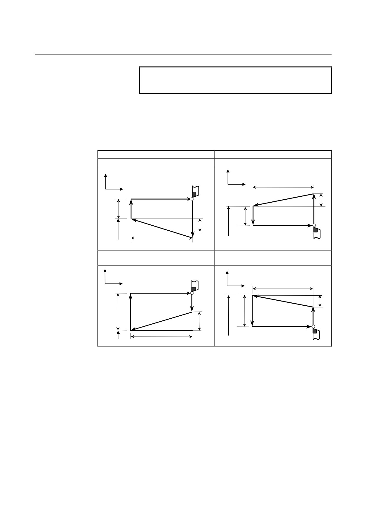
The tool path is determined according to the relationship between the
sign of the taper amount (address R) and the cutting end point in the
direction of the length in the absolute or incremental programming as
follows.
Outer diameter machining
Internal diameter machining
1. U < 0, W < 0, R < 0
2. U > 0, W < 0, R > 0
X
X
W
Z
Z
4(R)
2(F)
R
U/2
3(F)
1(R)
X
U/2
3(F)
1(R)
R
X
2(F)
4(R)
W
3. U < 0, W < 0, R > 0
4. U > 0, W < 0, R < 0
at |R|≤|U/2|
at |R|≤|U/2|
X
X
Z
W
Z
4(R)
1(R)
R
2(F)
X
U/2
3(F)
U/2
3(F)
2(F)
1(R)
R
4(R)
W
X
- Canceling the mode
To cancel the canned cycle mode, specify a group 01 G code other
than G90, G92, or G94.
- 42 -
4.FUNCTIONS TO SIMPLIFY
B-64304EN-1/01
PROGRAMMING
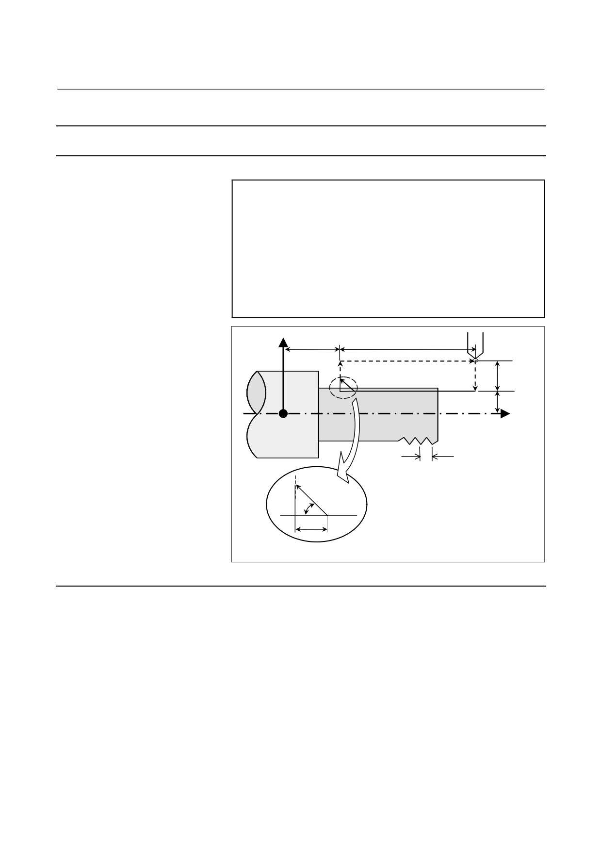
PROGRAMMING
4.1.2
Threading Cycle (G92)
4.1.2.1
Straight threading cycle
Format
G92 X(U)_Z(W)_F_Q_;
X_,Z_ : Coordinates of the cutting end point (point A' in the
figure below) in the direction of the length
U_,W_ : Travel distance to the cutting end point (point A' in
the figure below) in the direction of the length
Q_
: Angle for shifting the threading start angle
(Increment: 0.001 degrees,
Valid setting range: 0 to 360 degrees)
F_
: Thread lead (L in the figure below)
X axis
Z
W
4(R)
A
3(R)
1(R)
2(F)
U/2
A’
X/2
Z axis
(R) ... Rapid traverse
(F)
Cutting feed
L
Approx.
(The chamfered angle in the left figure is 45
45°
degrees or less because of the delay in the
r
servo system.)
Detailed chamfered thread
Fig. 4.1.2 (c) Straight threading
Explanation
The ranges of thread leads and restrictions related to the spindle speed
are the same as for threading with G32.
- Operations
A straight threading cycle performs four operations:
(1) Operation
1 moves the tool from the start point
(A) to the
specified coordinate of the second axis on the plane (specified
X-coordinate for the ZX plane) in rapid traverse.
(2) Operation 2 moves the tool to the specified coordinate of the first
axis on the plane (specified Z-coordinate for the ZX plane) in
cutting feed. At this time, thread chamfering is performed.
(3) Operation 3 moves the tool to the start coordinate of the second
axis on the plane (start X-coordinate for the ZX plane) in rapid
traverse. (Retraction after chamfering)
- 43 -