FANUC Series 0i-MODEL D, FANUC Series 0i Mate-MODEL D. MAINTENANCE MANUAL - page 14
10.TROUBLESHOOTING
B-64305EN/03
-
Checking the LCD cable and backlight cable
Check that the LCD and backlight cables are connected firmly to the corresponding connectors.
These cables are connected before shipment from FANUC. This check is, however, required because the
cables may be disconnected during maintenance.
-
Checking the installation of the necessary software
If necessary software is not stored in the FROM module, the CNC may not start up.
-
Checking a failure of printed-circuit boards
If the main board fails, the CNC may not start up.
Confirm that printed-circuit boards are securely connected through connectors.
If any of the above actions does not solve the problem, replace the inverter board or main board.
10.8 INPUT FROM AND OUTPUT TO I/O DEVICES CANNOT BE
PERFORMED, INPUT/OUTPUT CANNOT BE PERFORMED
PROPERLY
Causes and Countermeasures
If the I/O Link is not established, if the signals from an I/O device cannot be input normally to the CNC,
or if the signals from the CNC cannot be output to an I/O device, the probable causes include the
following:
• The I/O device is not turned on, or the power supply is not at the appropriate voltage.
• The I/O Link cable is not connected correctly or appropriately.
• The grounding is not correct.
• The input/output signals are not connected correctly.
• I/O Link allocation is not performed, or is not performed properly.
-
Checking PMC alarms
ER32 NO I/O DEVICE
If "ER32 NO I/O DEVICE" is displayed on the alarm screen of the PMC, no I/O devices are recognized.
ER97 IO LINK FAILURE
If "ER97 I/O LINK CONNECTION ERROR CHxx yyGROUP" appears on the PMC alarm screen, the
setting of the I/O device connection count in channel xx of I/O Link does not match the I/O Link
connection count that was allocated actually.
-
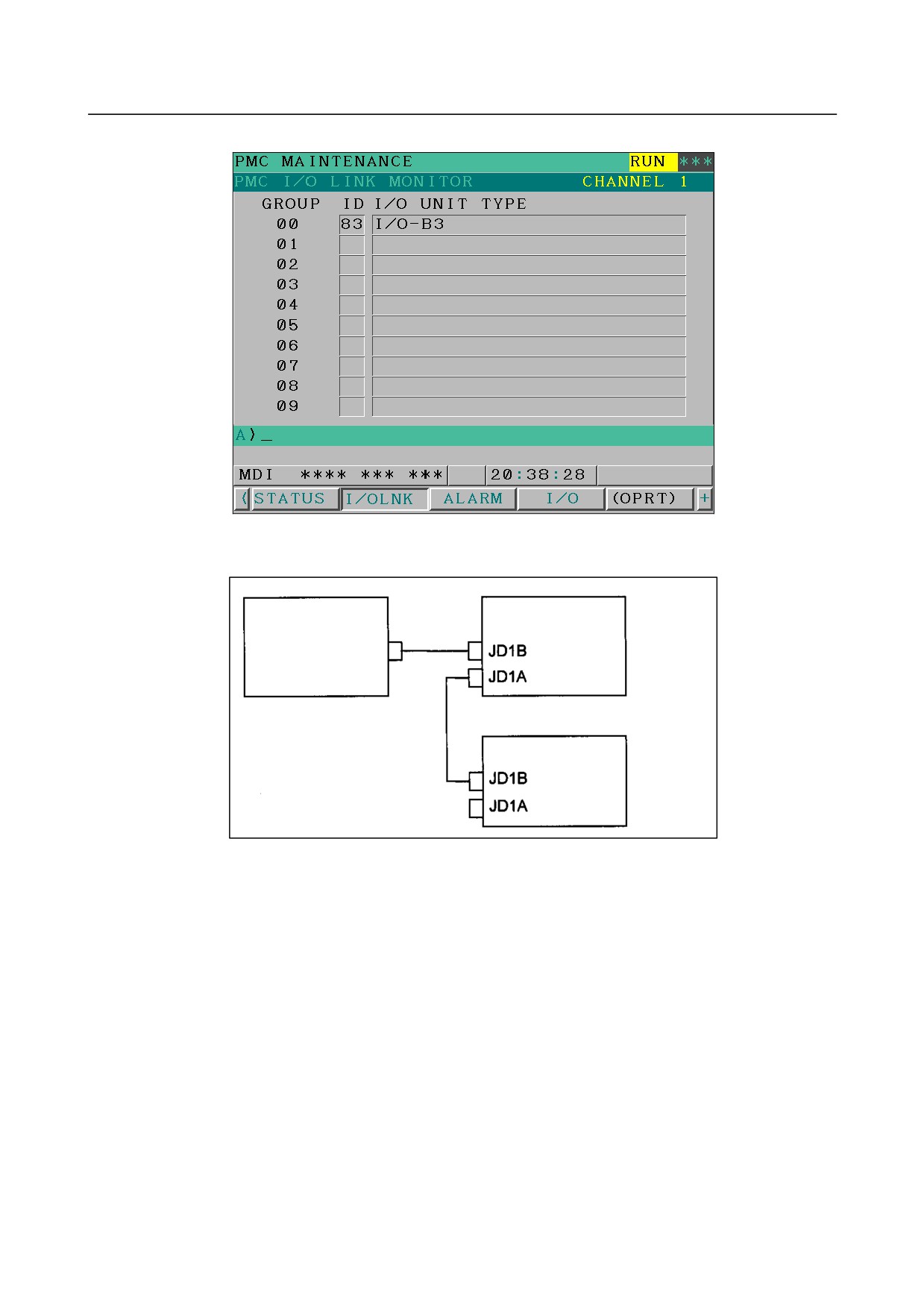
Checking the PMC I/O Link screen
Press function key
, soft key [PMCMNT], and soft key [I/O LNK]. The I/O devices recognized by
the CNC are displayed. From this screen, the devices that are connected normally can be determined.
- 374 -
B-64305EN/03
10.TROUBLESHOOTING
<Screen display example>
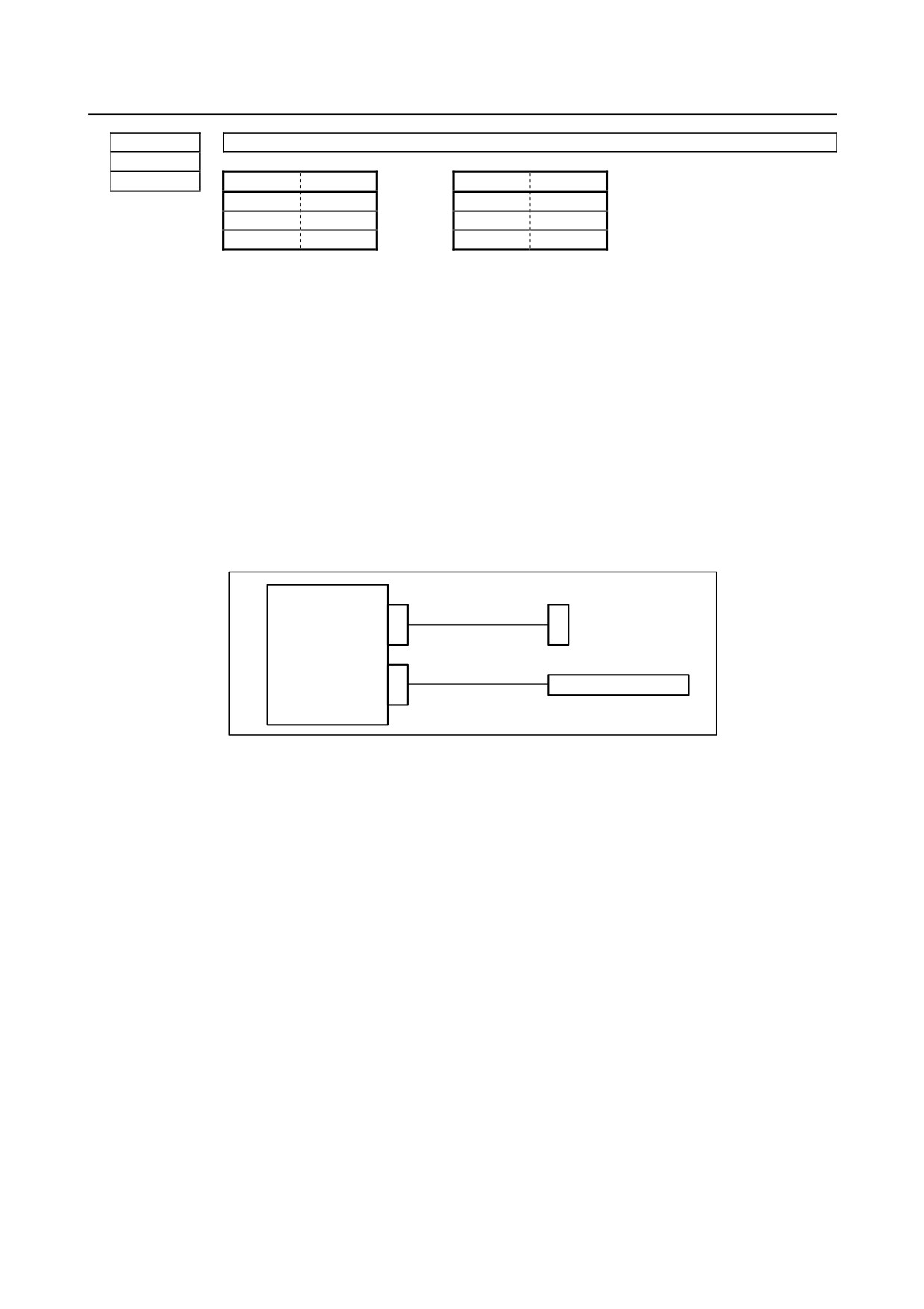
This example indicates that the I/O Link is as shown in the figure below.
I/O module for
Control unit
connector panel
JD51A
Group 0
Operator's panel I/O
module
Group 1
-
Checking the power supplies of the I/O devices
Check that the connected I/O devices are connected properly to the power supplies and that the voltages
are as prescribed.
Check that the power-on sequence is correct.
<Time at which an I/O device is to be turned on>
Before the CNC is turned on or within 500 ms after the CNC is turned on
If the CNC is turned off, the I/O device needs to be turned off once.
-
Checking cable connection
As in the example shown on the previous page, I/O Link cables are used to connect JD1A (JD51A) and
JD1B.
JD1A (JD51A) represents an upper unit while JD1B represents a lower unit.
Check that the cables are connected correctly.
-
Checking ground connection
Check that the ground wires are connected and are not loose.
- 375 -
10.TROUBLESHOOTING
B-64305EN/03
-
Checking I/O connection
Check that the input/output signals to be connected to each I/O device are connected correctly.
For operator's panel I/O modules and for connector panel I/O modules, also check that the 0 V or +24 V
input signal is connected to the common pin and that the +24 V output signal is connected to the DO
common pin.
-
Checking I/O Link allocation
Check that I/O Link allocation has been performed correctly.
Press function key
, soft key
[PMCCNF], soft key [MODULE], and soft key [EDIT]. The
allocation edit screen appears.
After editing allocation, be sure to write the sequence program onto the flash ROM using the PMC data
I/O screen. Otherwise, the changes will be lost when the power is turned off.
10.9 IN A CONNECTOR PANEL I/O UNIT, DATA IS INPUT TO
AN UNEXPECTED ADDRESS
If data is input to an invalid address in a connector panel I/O unit (for example, data that should be input
to X004 is actually input to X010 in a connector panel I/O unit), the most likely causes are as follows:
(1) The I/O Link allocation is wrong.
→ Perform the check described in Section 10.8.
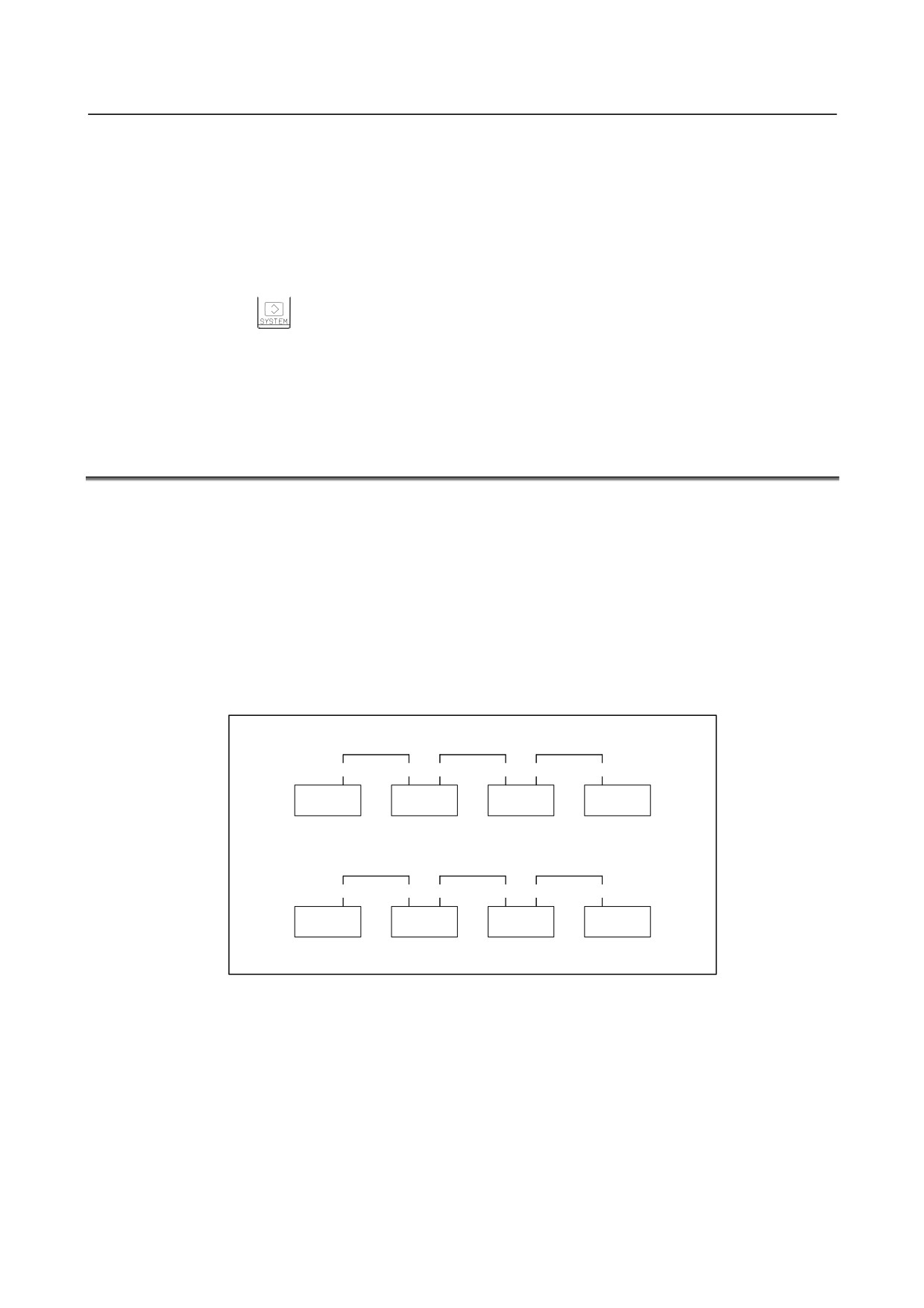
(2) The unit-to-unit cables (CA52-to-CA53) are not connected correctly.
If the connection is wrong, expansion unit 1 is allocated the address of expansion unit 3, as shown
below.
→ Connect the unit-to-unit cables as shown below:
Correct connection (the allocation starts with X0)
CA52
CA53 CA52
CA53 CA52
CA53
Basic
Expansion 1
Expansion 2
Expansion 3
X0-2
X3-5
X6-8
X9-11
Incorrect connection (the allocation starts with X0)
CA52
CA52 CA53
CA53 CA52
CA53
Basic
Expansion 1
Expansion 2
Expansion 3
X0-2
X9-11
X6-8
X3-5
(3) The setting of the rotary switch on an expansion unit is wrong
If the rotary switch is set to 1, one unit number is skipped. If set to 2, two unit numbers are skipped.
Usually, the setting must be 0. (For those units without a rotary switch, unit numbers cannot be
skipped.)
→ See the following example and refer to the Section 4.6, “SETTING I/O MODULES.”
- 376 -

B-64305EN/03
10.TROUBLESHOOTING
Example) Rotary switch setting on expansion unit 1=1
CA52
CA53
Basic
Expansion 1
X0-2
X6-8
⇐ X3 to X5 are skipped.
10.10 IN A CONNECTOR PANEL I/O UNIT, NO DATA IS OUTPUT
TO AN EXPANSION UNIT
The most likely cause is that power is not being supplied to the expansion unit.
→ Check whether +24-V power is supplied to No. 18 pin and No. 50 pin of the expansion unit, DI and
DO signals are not input and output.
→ Check whether +24-V power is supplied to No. 1 pin and No. 33 pin of the expansion unit, when DI
signals are input and DO signals are not output.
- 377 -
10.TROUBLESHOOTING
B-64305EN/03
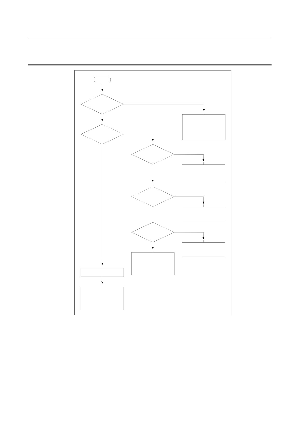
10.11 ALARM SR0085 TO SR0087 (READER/PUNCHER
INTERFACE ALARM)
START
YES
Alarm SR0085?
NO
-
Check baud rate and
other I/O parameters
-
I/O device is faulty
YES
Alarm SR0086?
NO
NO
Is I/O parameter
correct?
YES
-
Reset the parameter
according to the item
of data I/O.
OFF
Is power of I/O ?
ON
-
Turn on I/O device
NO
Is cable connection
right?
YES
-
Connect the cable
-
I/O device is faulty
-
Main board is faulty
Alarm SR0087?
-
I/O device is faulty
-
Main board d is faulty
Causes
(a) Parameters on reader/puncher interface are not correct.
Check the following setting data and parameters.
(b) External I/O device or host computer is faulty.
(c) Main board is faulty.
(d) Cable between NC and I/O device is faulty.
Countermeasures
(a) Parameters on reader/puncher interface are not correct.
Check the following setting data and parameters:
- 378 -
B-64305EN/03
10.TROUBLESHOOTING
-
Setting data
PUNCH CODE=0 OR 1 (0: EIA,1:ISO)
Select ISO or EIA according to the type of I/O device.
If punch code does not match, alarm SR0086 will generate.
-
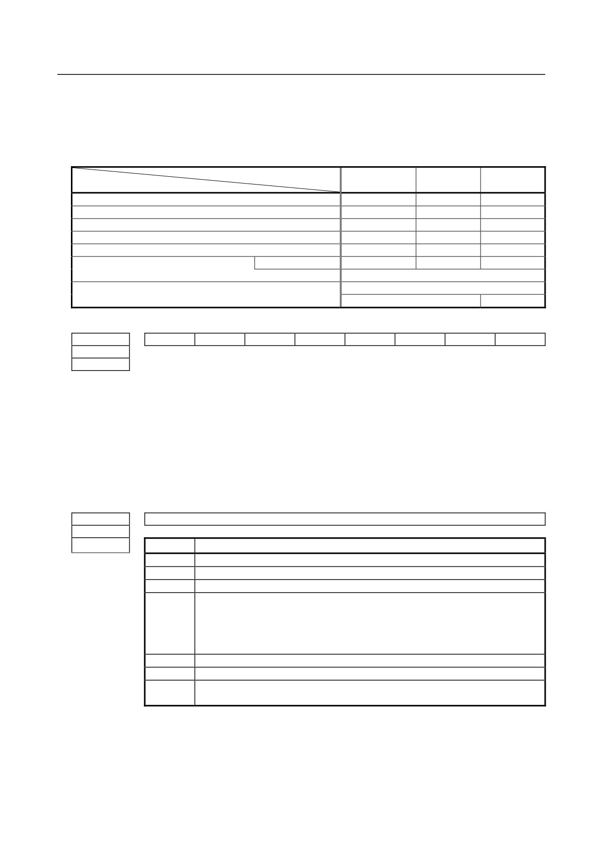
Parameter
Value of parameter No. 0020
0
1
2
Function
Feed
0101#7
0111#7
0121#7
Data input/output code
0101#3
0111#3
0121#3
Stop bit
0101#0
0111#0
0121#0
Type of I/O device
102
112
122
Baud rate
103
113
123
0135#3
-
-
-
Communication method
RS-232C
MAIN BOARD
Connector
JD36A
JD36B
#7
#6
#5
#4
#3
#2
#1
#0
0101
NFD
ASI
SB2
0111
0121
NFD 0: Feed is output before and after data in data output
(FANUC PPR)
1: Feed is not output (standard).
ASI 0: EIA or ISO is used during input/output.
(Input: The code used is identified automatically.
Output: The code used depends on the punch code of setting data.)
1: ASCII codes are used during output.
(The punch code of setting data needs to be set to 1.)
SB2 0: No. of stop bits is 1.
1: No. of stop bits is 2.
0102
Type of I/O device
0112
0122
Value
TYPE OF I/O DEVICE
0
RS-232-C (Used control codes DC1 to DC4)
1
FANUC CASSETTE ADAPTOR 1 (FANUC CASSETTE B1/ B2)
2
FANUC CASSETTE ADAPTOR 3 (FANUC CASSETTE F1)
FANUC PROGRAM FILE Mate,
FANUC FA CARD ADAPTOR
3
FANUC FLOPPY CASSETTE ADAPTOR,
FANUC Handy File,
FANUC SYSTEM P-MODEL H
4
RS-232-C (Not used control codes DC1 to DC4)
5
Portable tape reader
FANUC PPR, FANUC SYSTEM P-MODEL G,
6
FANUC SYSTEM P-MODEL H
- 379 -
10.TROUBLESHOOTING
B-64305EN/03
0103
Baud rate
0113
0123
Value
Baud rate
Value
Baud rate
7
600
10
4800
8
1200
11
9600
9
2400
12
19200
(b)
External I/O device or Host computer is in trouble
(i)
Check whether the setting on communication of external I/O device or host computer is the
same as that of the CNC. (baud rate, stop bits, etc.)
If they are not the same, change the setting.
(ii) When spare I/O device presents, check whether it is possible to realize communication using
the spare I/O device.
(c)
Main board is faulty
(i)
When parameter No.0020 is 0, 1, or 2 (JD36A, JD36B of Main board)
Replace the module since main board may be faulty.
(d)
Cable between CNC and I/O device is faulty.
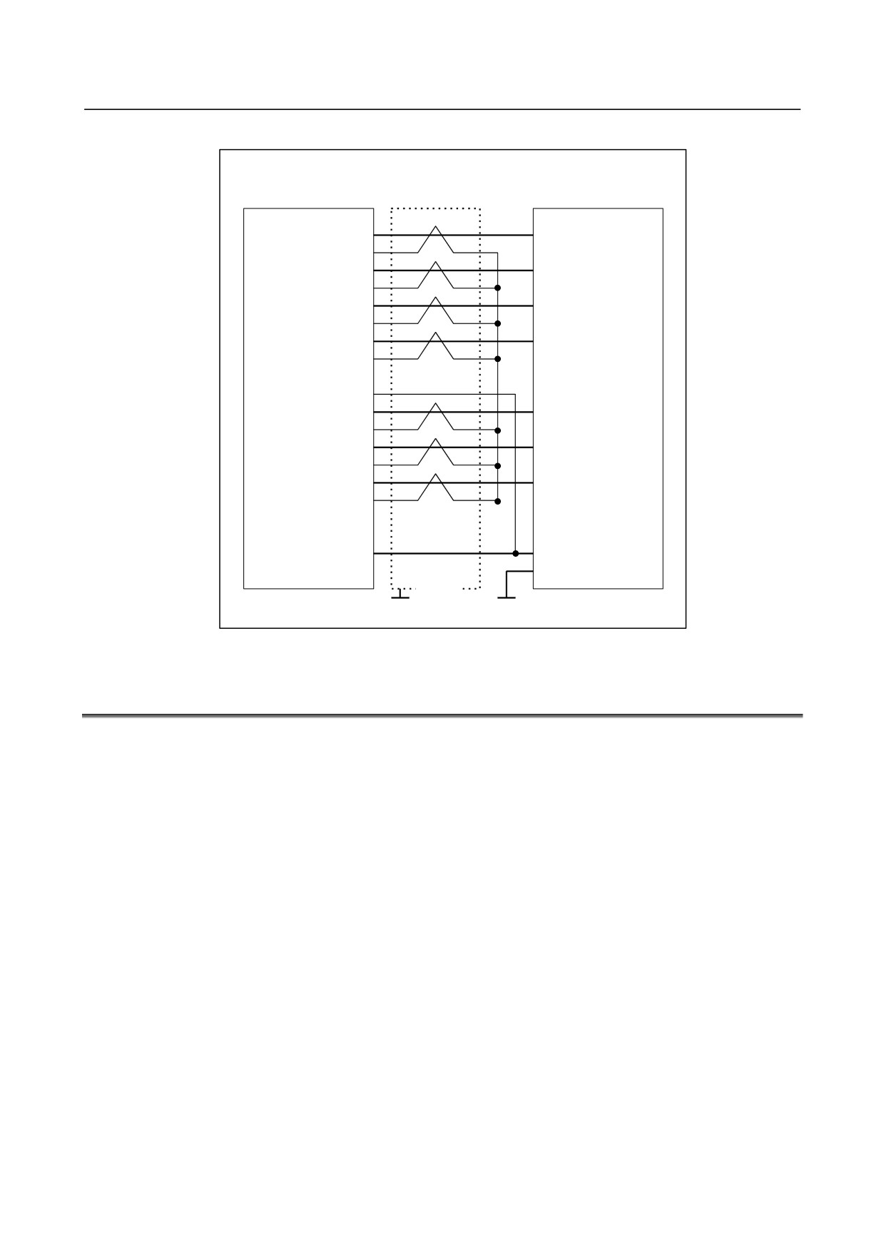
Check the cable for disconnection or wrong connection.
-
Connection
Main board
RS-232-C (JD36A)
Punch panel
RS-232-C (JD36B)
Such as I/O device
- 380 -
B-64305EN/03
10.TROUBLESHOOTING
-
Cable connection
RS-232-C
(JD36A)
(JD36B)
Punch panel
RD
(01)
(03)
RD
0V
(02)
DR
(03)
(06)
DR
0V
(04)
CS
(05)
(05)
CS
0V
(06)
CD
(07)
(08)
CD
0V
(08)
(09)
+24V
(10)
SD
(11)
(02)
SD
0V
(12)
ER
(13)
(20)
ER
0V
(14)
RS
(15)
(04)
RS
0V
(16)
(07)
SG
(17)
(18)
+24V
(19)
(25)
+24V
(20)
(01)
FG
Shield
Connector : Half-pitch
Connector :DBM-25S
G
G
20-pins (PCR)
10.12 ALARM PS0090 (REFERENCE POSITION RETURN IS
ABNORMAL)
Contents
A reference position return was performed when the condition "the one turn signal is received more than
once when an axis is fed in the reference position return direction at a speed at which the positional
deviation (DGN.300) is 128 pulses or more" was not satisfied.
- 381 -
10.TROUBLESHOOTING
B-64305EN/03
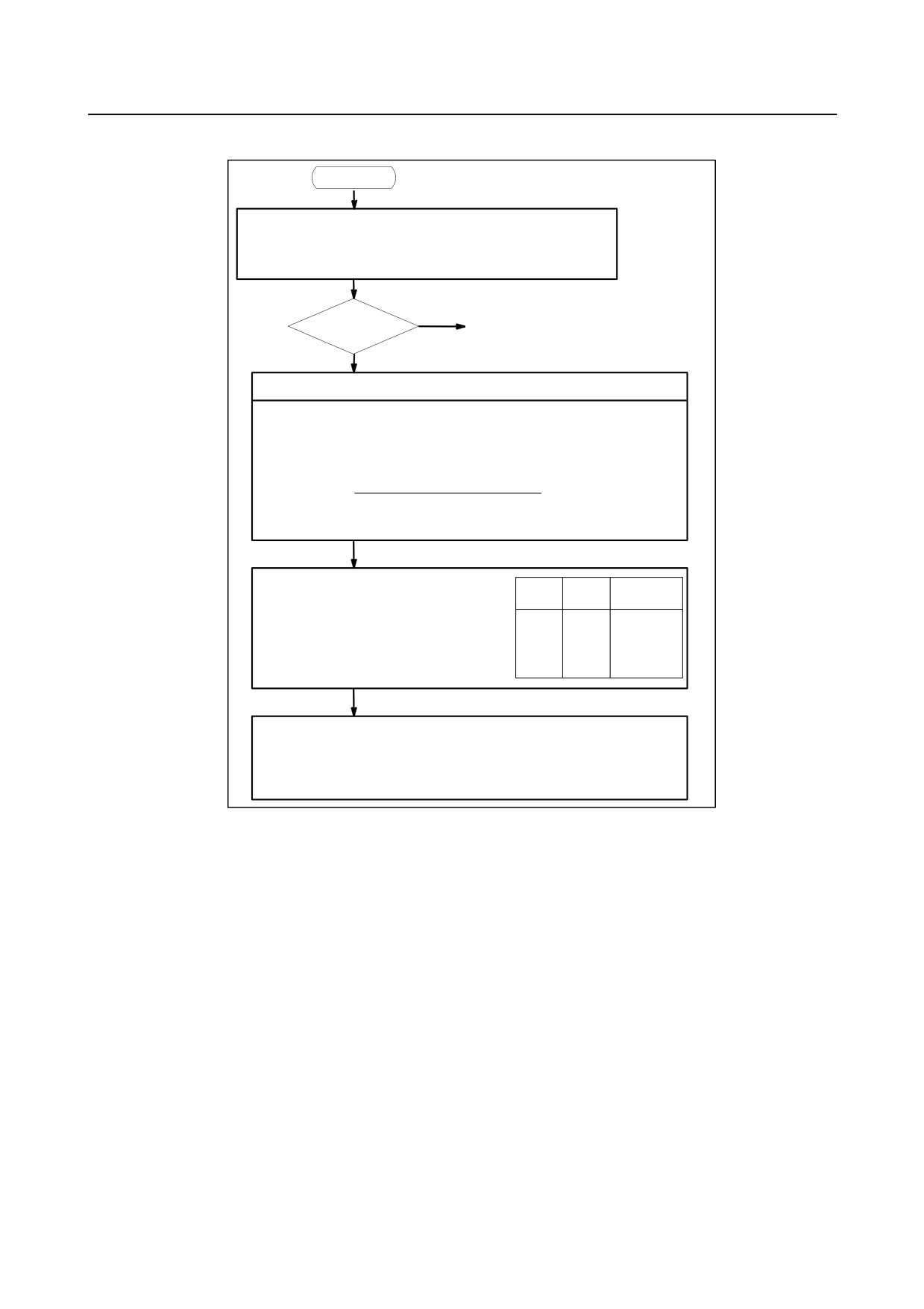
Countermeasures
START
Check whether the positional error amount (No. 300 value on the
Position error
diagnosis screen) in the reference position return direction is 128 or
amount : DGN
more during a reference position return or during axis movement
300
before a reference position return
YES
128 or more
(1) Next page
NO
Raise the speed
Check feed rate command:
Parameter No. 1420 F
:
Rapid traverse rate
[mm/min]
Parameter No. 1424
Manual rapid traverse rate
[mm/min]
Parameter No. 1825 G
:
Servo loop gain [0.01sec-1]
F×5000/3
Position error =
G × detection unit [μm/PULSE]
Detection unit
: Move amount to a command pulse
Check rapid traverse override signals :
ROV1
ROV2
Override
ROV1 G014.0
0
0
100%
ROV2 G014.1
0
1
50%
1
0
25%
Parameter No. 1421 F0 rate
1
1
F0 rate
Check reference position return deceleration signal
*DEC1 to *DEC5 X009.0 to X009.4
When reference position return is started from deceleration signal 0, feed
rate becomes FL rate.
Parameter No. 1425 FL rate
- 382 -
B-64305EN/03
10.TROUBLESHOOTING
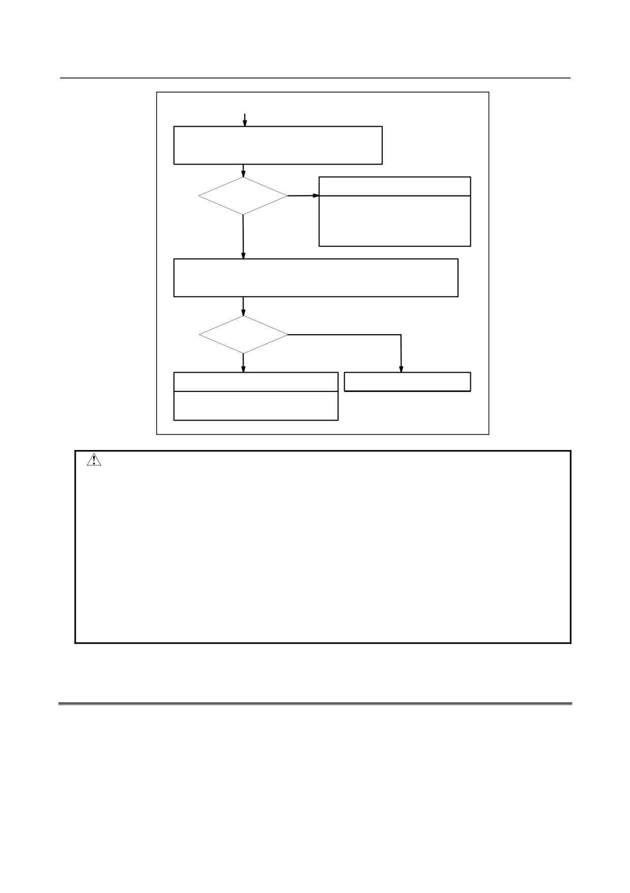
(1)
Check whether the motor rotated more than one
rotation (one rotation signal is issued ) at faster than
128 pulses of position error amount.
NO
Return start position is too close
Rotated ?
- Move the return start position away.
- Move the machine at faster that
YES
128 pulses for more than one
rotation to wards RP.
Check that voltage of Pulsecoder is higher than 4.75 V.
To measure Pulsecoder voltage, remove the motor cover and measure on
pulse coder PCB at across + and - or +5V and 0V terminals.
NO
More than 4.75V
YES
Hardware failure
Pulse coder power voltage is low
- Change Pulsecoder or motor
CAUTION
1 After replacing the pulse coder or motor, be sure to set the reference position
again.
2 A speed more than 128 pulses is required because if speed is lower that this,
one-rotation signal does not function stably, causing improper position detection.
3 If bit 0(PLC0) of parameter No. 2000 is set to 1, a speed corresponding to a
positional deviation of 1280 pulses or more is required.
4 Parameter No. 1836 can be set to 128 or less, as the minimum positional
deviation with which reference position return is possible. (If the parameter is set
to 0, 128 is assumed as the minimum positional deviation. When bit 0 (PLC0)
of parameter No. 2000 is 1, set the minimum positional deviation with which
reference position return is possible to 10 times the setting of parameter No.
1836.)
10.13 ALARM DS0300 (REQUEST FOR REFERENCE POSITION
RETURN)
Absolute position data in the serial Pulsecoder was lost.
(This alarm will be generated when serial Pulsecoder is exchanged or position feedback signal cable of
the serial Pulsecoder is disconnected).
Countermeasures
Machine position must be memorized using the following method:
- 383 -
10.TROUBLESHOOTING
B-64305EN/03
-
When the deceleration dog is present
1
Execute manual reference position return only for an axis for which this alarm was generated. If
manual reference position return cannot be executed because another alarm occurs, clear the alarm
and then execute reference position return.
2
Press
key at the end of reference position return to release the alarm.
-
When the deceleration dog is not present
Execute dogless reference position setting to memorize the reference position.
-
When serial Pulsecoder is changed
Since the reference position is different from the former one, change the grid shift value (parameter No.
1850) to correct the position.
Related parameters
#7
#6
#5
#4
#3
#2
#1
#0
1815
APCx
APZx
#4 APZx Machine position and position on absolute position detector when the absolute position
detector is used
0: Not corresponding
1: Corresponding
When an absolute position detector is used, after primary adjustment is performed or after
the absolute position detector is replaced, this parameter must be set to 0, power must be
turned off and on, then manual reference position return must be performed. This
completes the positional correspondence between the machine position and the position
on the absolute position detector, and sets this parameter to 1 automatically.
#5 APCx Position detector
0: Other than absolute position detector
1: Absolute position detector (absolute pulse coder)
10.14 ALARM SV0401 (V READY OFF)
Causes and Countermeasures
This alarm is issued if the servo ready signal VRDY of a servo amplifier does not turn on or if the signal
turns off during operation.
There are cases in which this alarm is issued because another servo alarm is issued. If this occurs, first
take the action for the first alarm.
Check the power magnetic circuit around the amplifier. The servo amplifier or the axis cards on the CNC
may be defective.
- 384 -
B-64305EN/03
10.TROUBLESHOOTING
-
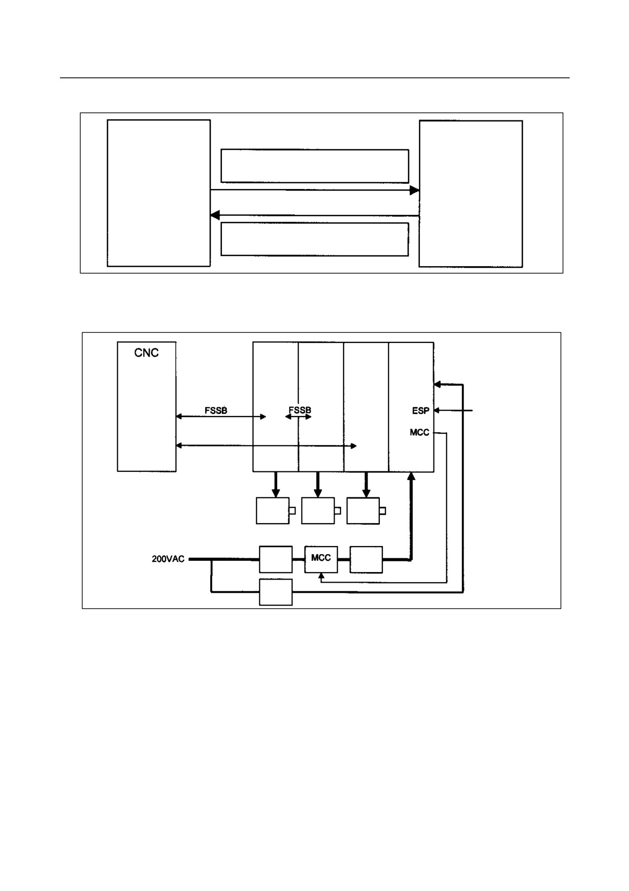
VRDY
CNC
Servo amplifier
MCON: From the CNC to the servo amplifier
(Turn MCC on to request the activation of the
servo motor)
VRDY: From the servo amplifier to the CNC
(Notifies that the servo is ready)
The exchange of this information is performed via the FSSB (optical cable).
-
Example of connection around the amplifier (Typical example)
Power
Servo
Servo
Spindle
Supply
amplifier
amplifier
amplifier
(PS)
Control
power
supply
Emergency stop
circuit
Serial spindle
Servo
Servo
Spindle
motor
motor
motor
3-phase
Circuit
AC
breaker
reactor
Single-p
hase
Circuit
breaker
Check items
• Check the value of diagnosis information No. 358 (V ready-off information), identify the possibly
faulty location according to the instructions of the information, and check the following items.
(For details of diagnosis information No. 358, see Subsection 1.3.2, “Contents Displayed,” in
Section 1.3, “DIAGNOSIS FUNCTION,” in this manual.)
-
Is the Power Supply (PS) control power supply on?
-
Has an emergency stop been canceled?
-
Is MCC on? If there is an external MCC sequence in addition to the MCC contact of the Power
Supply (PS), check that sequence also.
-
Is the power for driving MCC supplied?
-
Is the breaker on?
-
Has some alarm been issued in the Power Supply (PS) or spindle amplifier?
-
Replacing the servo amplifier
If no problem is found in the power magnetic circuit around the amplifier, replace the servo amplifier.
- 385 -
10.TROUBLESHOOTING
B-64305EN/03
-
Replacing the axis cards
If the above action does not solve the problem, replace the axis cards.
10.15 ALARM SV0404 (V READY ON)
Causes and Countermeasures
This alarm is issued if the servo ready signal (VRDY) of a servo amplifier remains on.
The servo amplifier or the axis cards on the CNC may be defective.
-
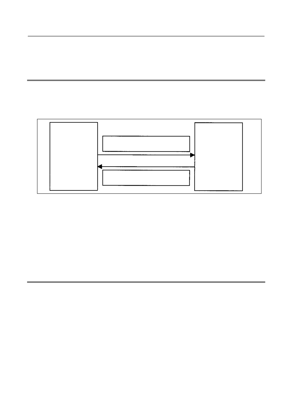
VRDY
CNC
Servo amplifier
MCON: From the CNC to the servo amplifier
(Turn MCC on to request the activation of the
servo motor)
VRDY: From the servo amplifier to the CNC
(Notifies that the servo is ready)
The exchange of this information is performed via the FSSB (optical cable).
This alarm is issued if VRDY remains on when the CNC turns MCON off or if VRDY turns on before the
CNC turns MCON on.
-
Replacing the servo amplifier
The servo amplifier may be defective. Replace the servo amplifier.
-
Replacing the axis cards
If replacing the servo amplifier does not solve the problem, replace the axis cards.
10.16 ALARM SV0462 (SEND CNC DATA FAILED)
ALARM SV0463 (SEND SLAVE DATA FAILED)
Causes and Countermeasures
Alarm SV0462 is issued if a slave (servo amplifier) cannot receive correct data due to an FSSB
communication error.
Alarm SV0463 is issued if the CNC cannot receive correct data due to an FSSB communication error.
If these alarms are issued, the alarm message indicates the number of the defective axis (axis name).
-
Servo amplifier or optical cable
Any of the optical cables between the amplifier corresponding to the axis number indicated by the alarm
message and the CNC controller may be defective.
Or, any of the first amplifier to the amplifier corresponding to that axis number may be defective.
-
Axis cards
The axis cards installed on the CNC may be defective.
- 386 -

B-64305EN/03
10.TROUBLESHOOTING
10.17 ALARM SV0417 (DIGITAL SERVO SYSTEM IS
ABNORMAL)
Digital servo parameters are abnormal.
(Digital servo parameters are set incorrectly.)
Countermeasures
1
Confirm the setting value of the following parameters:
Parameter No. 2020
: Motor format number
Parameter No. 2022
: Motor rotation direction
Parameter No. 2023
: Number of pulses of velocity feedbacks
Parameter No. 2024
: Number of pulses of position feedback
Parameter No. 1023
: Servo axis number
Parameter No. 2084
: Flexible feed gear ratio
Parameter No. 2085
: Flexible feed gear ratio
Confirm the details with diagnosis function of CNC side.
2
Change the setting of this parameter to 0.
Parameter No. 2047
: Observer parameter
10.18 ALARM OH0700 (OVERHEAT: CONTROL UNIT)
Causes and Countermeasures
This alarm is issued if the ambient temperature of the CNC control unit is abnormally high. As an
installation condition, the ambient temperature of the CNC must not exceed 58°C (for LCD-mounted type
CNC) or 55°C (for stand-alone type CNC).
-
Ambient temperature
A temperature monitoring circuit is installed on the main board, and causes this alarm to be issued if the
ambient temperature is abnormally high.
Take appropriate action to the cabinet that houses the CNC control unit so that the temperature falls
within the proper temperature range (0 to 58°C (for LCD-mounted type CNC) or 0 to 55°C (for
stand-alone type CNC)).
If it is obvious that the ambient temperature is not abnormal, the main board may be defective.
10.19 ALARM OH0701 (OVERHEAT: FAN MOTOR)
Causes and Countermeasures
This alarm is issued if a fault occurs in any of the fan motors, such as the stoppage of a fan motor during
the operation of the CNC.
-
Fan motors
Fan motors are installed in the uppermost portion of the CNC control unit. This alarm is issued if a fault
such as a stoppage occurs.
If this alarm is issued, replace the fan motor according to "2.9 REPLACING FAN MOTORS" or "3.8
REPLACING A FAN UNIT".
- 387 -
10.TROUBLESHOOTING
B-64305EN/03
10.20 ALARM SV5134 (FSSB: OPEN READY TIME OUT)
ALARM SV5137 (FSSB: CONFIGURATION ERROR)
ALARM SV5197 (FSSB: OPEN TIME OUT)
Causes and Countermeasures
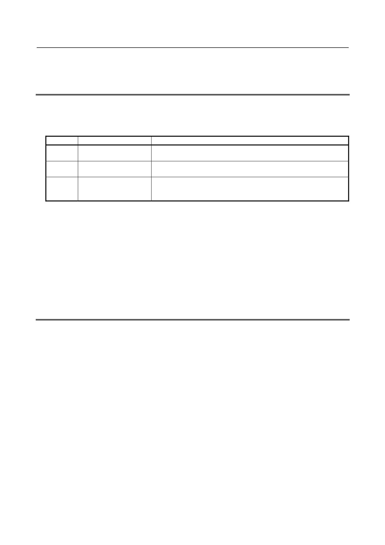
These alarms are issued due to a failure in the optical cable, axis card, or a slave such as a servo amplifier
connected to the FSSB.
No.
Message
Description
SV5134
FSSB:OPEN READY
In the initialization, the FSSB could not be in an open ready sate. The axis
TIME OUT
card is thought to be defective.
SV5137
FSSB:CONFIGURATION
An FSSB configuration error occurred.
ERROR
The connecting amplifier type is incompatible with the FSSB setting value.
SV5197
FSSB:OPEN TIME OUT
The FSSB cannot be opened even though the CNC allowed the FSSB to
be opened.
Or, the connection between the CNC and the amplifier in is incorrect.
-
Checking the parameter settings
Check that the FSSB-related parameters are set correctly.
-
Power supplies of the servo amplifiers
Check the power supplies of the servo amplifiers connected to the FSSB.
-
Replacing the axis cards, optical cables, and servo amplifiers
Replace the axis cards on the CNC.
Replace the optical cables and servo amplifiers connected to the FSSB, one at a time, to identify the
defective item.
10.21 ALARM SV5136 (FSSB: NUMBER OF AMPS IS SMALL)
Causes and Countermeasures
The number of servo amplifiers recognized by the FSSB is insufficient, compared with the number of
controlled axes.
-
FSSB setting screen
If this alarm is issued, display the amplifier setting screen from the FSSB setting screen. Only the servo
amplifiers recognized on the FSSB are displayed.
-
Optical cable or servo amplifier
The optical cable that connects together the last recognized amplifier and the next one may be defective.
Or, either of the amplifiers connected together with that optical cable may be defective. Check the power
supplies of the amplifiers.
-
Power fault of a servo amplifier
This alarm may be issued if a power fault occurs in a servo amplifier. A power fault occurs if the
amplifier control power supply voltage drops, if the +5 V conductor of the Pulsecoder cable is ground, or
for other reasons.
-
Axis cards
The axis cards installed on the CNC may be defective.
- 388 -
B-64305EN/03
10.TROUBLESHOOTING
10.22 SERVO ALARMS (SV04**, SV06**)
For an explanation of the following servo alarms, refer to the FANUC AC SERVO MOTOR αi series,
AC SPINDLE MOTOR αi series, SERVO AMPLIFIER αi series Maintenance Manual (B-65285EN).
Number
Message
Description
SV0417
ILL DGTL SERVO PARAMETER
A digital serve parameter setting is incorrect.
[When bit 4 of diagnosis information No. 203 is 1.]
An illegal parameter was detected by the servo software. Identify
the cause with reference to diagnosis information No. 352.
[When bit 4 of diagnosis information No. 203 is 0.]
The CNC software detected an illegal parameter. Probable
causes are given below (see diagnosis information No. 280).
1) The value specified in parameter No. 2020 as the motor model
falls outside the specified range.
2) The motor rotation direction in parameter No. 2022 is not set to
a correct value (111 or -111).
3) The speed feedback pulse count per motor rotation in
parameter No. 2023 is set to a negative or other incorrect value.
4) The position feedback pulse count per motor rotation in
parameter No. 2024 is set to a negative or other incorrect value.
SV0420
SYNC TORQUE EXCESS
In feed axis control , for synchronization, the difference value of
torque between a master and slave axes exceeded the parameter
(No. 2031) setting value. This alarm occurs for a master axis.
SV0421
EXCESS ERROR(SEMI-FULL)
The difference between the feedback from the semi and full sides
exceeded the setting of parameter No.1729.
SV0422
EXCESS VELOCITY IN
In torque control, the commanded permissible velocity was
TORQUE
exceeded.
SV0423
EXCESS ERROR IN TORQUE
In torque control, the total permissible move value specified as a
parameter was exceeded.
SV0430
SV MOTOR OVERHEAT
The servo motor has overheated.
SV0431
CNV. OVERLOAD
Power Supply (PS) : Overheat
Servo Amplifier
: Overheat
SV0432
CNV. LOW VOLT CONTROL
Power Supply (PS) : The control power supply voltage has
dropped.
Servo Amplifier
: The control power supply voltage has
dropped.
SV0433
CNV. LOW VOLT DC LINK
Power Supply (PS) : Low DC link voltage
Servo Amplifier
: Low DC link voltage
SV0434
INV. LOW VOLT CONTROL
Servo Amplifier
: Low control power voltage
SV0435
INV. LOW VOLT DC LINK
Servo Amplifier
: Low DC link voltage
SV0436
SOFTTHERMAL(OVC)
The digital servo software detected a software thermal (OVC).
SV0437
CNV. OVERCURRENT POWER
Power Supply (PS) : Overcurrent on input circuit section.
SV0438
INV. ABNORMAL CURRENT
Servo Amplifier
: Motor overcurrent
SV0439
CNV. OVER VOLT DC LINK
Power Supply (PS) : The DC link voltage is too high.
Servo Amplifier
: The DC link voltage is too high.
SV0440
CNV. EX DECELERATION
Power Supply (PS) : Excessive generative discharge
POW.
Servo Amplifier
: Excessive generative discharge, or
abnormal error in generative power circuit
SV0441
ABNORMAL CURRENT
The digital servo software detected an abnormality in the motor
OFFSET
current detection circuit.
SV0442
CNV. CHARGE FAILURE
Power Supply (PS) : The spare charge circuit for the DC link is
abnormal.
SV0443
CNV. COOLING FAN FAILURE
Power Supply (PS) : Internal cooling fan failure.
Servo Amplifier
: Internal cooling fan failure.
SV0444
INV. COOLING FAN FAILURE
Servo Amplifier
: Internal cooling fan failure.
- 389 -
10.TROUBLESHOOTING
B-64305EN/03
Number
Message
Description
SV0445
SOFT DISCONNECT ALARM
The digital servo software detected a disconnected Pulsecoder.
SV0446
HARD DISCONNECT ALARM
The hardware detected a disconnected built-in Pulsecoder.
SV0447
HARD DISCONNECT(EXT)
The hardware detected a disconnected separate detector.
SV0448
UNMATCHED FEEDBACK
The sign of the feedback signal from the standalone detector is
ALARM
opposite to that from the feedback signal from the built-on
Pulsecoder.
SV0449
INV. IPM ALARM
Servo Amplifier
: The IPM (Intelligent Power Module) detected
an alarm.
SV0453
SPC SOFT DISCONNECT
Software disconnection alarm of the α Pulsecoder.
ALARM
Turn off the power to the CNC, then remove and insert the
Pulsecoder cable. If this alarm is issued again, replace the
Pulsecoder.
SV0454
ILLEGAL ROTOR POS DETECT
The magnetic pole detection function terminated abnormally.
The magnetic pole could not be detected because the motor did
not run.
SV0456
ILLEGAL CURRENT LOOP
An attempt was made to set the current loop that could not be set.
The amplifier pulse module in use does not comply with HIGH
SPEED HRV. Or, requirements to control are not satisfied in the
system.
SV0458
CURRENT LOOP ERROR
The specified current loop differs from the actual current loop.
SV0459
HI HRV SETTING ERROR
For two axes whose servo axis numbers (parameter No. 1023) are
consecutively even and odd numbers, HIGH SPEED HRV control
is possible for one axis and impossible for the other.
SV0460
FSSB DISCONNECT
The FSSB connection was discontinued.
Probable causes are:
1) The FSSB connection cable was disconnected or broken.
2) The amplifier was turned off .
3) In the amplifier, the low-voltage alarm occurred.
SV0462
SEND CNC DATA FAILED
The correct data could not be received on a slave side because of
the FSSB communication error.
SV0463
SEND SLAVE DATA FAILED
The correct data could not be received in the servo software side
because of the FSSB communication error.
SV0465
READ ID DATA FAILED
A read of the ID information for the amplifier has failed at
power-on.
SV0466
MOTOR/AMP. COMBINATION
The maximum current of an amplifier is different to that of a motor.
Probable causes are:
1) The connection command for an amplifier is incorrect.
2) The parameter (No.2165) setting is incorrect
SV0468
HI HRV SETTING ERROR(AMP)
An attempt was made to set up HIGH SPEED HRV control for use
when the controlled axis of an amplifier for which HIGH SPEED
HRV control could not be used.
SV0600
INV. DC LINK OVER CURRENT
DC link overcurrent.
SV0601
INV. RADIATOR FAN FAILURE
External radiator cooling fan failure.
SV0602
INV. OVERHEAT
The servo motor has overheated.
SV0603
INV. IPM ALARM(OH)
The IPM (Intelligent Power Module) detected an overheat alarm.
SV0604
AMP. COMMUNICATION
The communication between Servo amplifier and Power Supply
ERROR
(PS) is in error.
SV0605
CNV. EX. DISCHARGE POW.
Power Supply (PS) : The motor regenerative power is too much.
SV0606
CNV. RADIATOR FAN FAILURE
Power Supply (PS) : External radiator cooling fan failure.
SV0607
CNV. SINGLE PHASE FAILURE
Power Supply (PS) : The input power supply has a missing phase.
If the hardware on the CNC is suspected to be defective as a result of examination, replace the axis cards.
- 390 -
B-64305EN/03
10.TROUBLESHOOTING
10.23 SPC ALARMS (SV03**)
For an explanation of the following SPC alarms (serial Pulsecoder alarms), refer to the FANUC AC
SERVO MOTOR αi series, AC SPINDLE MOTOR αi series, SERVO AMPLIFIER αi series
Maintenance Manual (B-65285EN).
Number
Message
Description
SV0360
ABNORMAL CHECKSUM(INT)
The checksum alarm occurred on the built-in Pulsecoder.
SV0361
ABNORMAL PHASE
The phase data abnormal alarm occurred on the built-in
DATA(INT)
Pulsecoder.
SV0362
ABNORMAL REV. DATA(INT)
The speed count abnormal alarm occurred on the built-in
Pulsecoder.
SV0363
ABNORMAL CLOCK(INT)
The clock alarm occurred on the built-in Pulsecoder.
SV0364
SOFT PHASE ALARM(INT)
A digital servo soft detected an abnormality on the built in
Pulsecoder.
SV0365
BROKEN LED(INT)
The digital servo software detected abnormal data on the built-in
Pulsecoder.
SV0366
PULSE MISS(INT)
A pulse error occurred on the built-in Pulsecoder.
SV0367
COUNT MISS(INT)
A count error occurred on the built-in Pulsecoder.
SV0368
SERIAL DATA ERROR(INT)
The communications data could not be received from the built-in
Pulsecoder.
SV0369
DATA TRANS. ERROR(INT)
A CRC error or stop bit error occurred in the communications data
from the built-in Pulsecoder.
SV0380
BROKEN LED(EXT)
Separate detector error
SV0381
ABNORMAL PHASE (EXT)
An abnormal alarm in the position data occurred on the separate
detector.
SV0382
COUNT MISS(EXT)
A count error occurred on the separate detector.
SV0383
PULSE MISS(EXT)
A pulse error occurred on the separate detector.
SV0384
SOFT PHASE ALARM(EXT)
The digital servo software detected abnormal data on the separate
detector.
SV0385
SERIAL DATA ERROR(EXT)
The communications data could not be received from the separate
detector.
SV0386
DATA TRANS. ERROR(EXT)
A CRC error or stop bit error occurred in the communications data
from the standalone detector.
SV0387
ABNORMAL ENCODER(EXT)
An abnormality occurred on a separate detector. For more
information, contact the scale manufacturer.
10.24
SPINDLE ALARMS (SP90**)
For an explanation of the following spindle alarms, refer to the FANUC AC SERVO MOTOR αi series,
AC SPINDLE MOTOR αi series, SERVO AMPLIFIER αi series Maintenance Manual (B-65285EN).
Number
Contents
SP9001 to later: Spindle_n
n-th spindle alarm (Spindle alarm display 01 or larger)
10.25 SYSTEM ALARMS (SYS ALM***)
10.25.1 Overview
The CNC makes a transition to the special processing state called the system alarm state when a state that
disables the continuation of normal system operation is detected.
- 391 -
10.TROUBLESHOOTING
B-64305EN/03
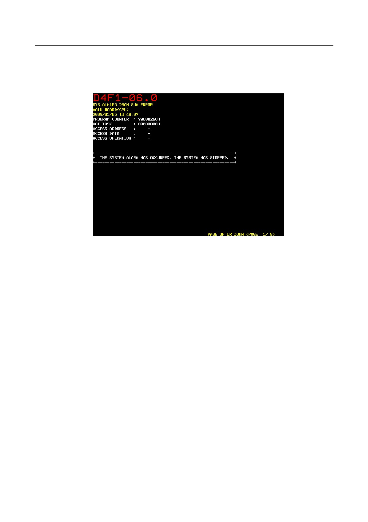
When the system alarm state is entered, the CNC screen display is switched and the following operations
are performed:
• Servo and spindle amplifier excitation is turned off.
• Disconnection of I/O link communication
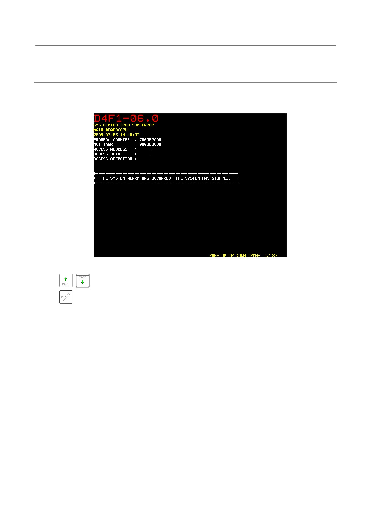
Example of system alarm screen
Types of System Alarms
System alarms are classified into three types according to the following causes:
• Software causes
• Hardware causes
• Others
-
Software causes
Mainly, the CNC system software detects software errors.
Typical causes are as follows:
• Conflict in processing/data detected by the internal state monitoring software
• Access to outside of the valid data/instruction ranges
• Division by zero
• Stack overflow
• Stack underflow
• DRAM checksum error
-
Hardware causes
Mainly, hardware detects hardware errors.
Typical causes are as follows:
• Parity error (DRAM, SRAM, cache)
• Bus error
• Power supply alarm
• FSSB cable disconnection
-
Others
Moreover, system alarms are caused by the following:
• Causes detected by peripheral software
• Servo software (such as watchdog)
- 392 -
B-64305EN/03
10.TROUBLESHOOTING
• PMC software (such as an I/O link communication error)
10.25.2 Operations on the System Alarm Screen
Description of system alarm screen
When a system alarm is issued, the screen display is switched to a screen as shown below.
This screen is referred to as the system alarm screen.
The system alarm screen consists of several pages of information.
The following key operations are used:
,
Switches between pages.
Executes the IPL monitor.
Saving of system alarm information
Various information items related to a system alarm are automatically saved in the SRAM.
The SRAM can store information about the latest two system alarms.
If a third system alarm is issued when information about the latest two system alarms is stored, the
information about the oldest system alarm is discarded, and information about the new system alarm is
saved.
Output of system alarm information
The system alarm information, which was automatically saved in the SRAM, can be output to a memory
card with the IPL monitor.
1.
Start the IPL monitor.
If the system alarm screen is displayed when a system alarm is issued, press the reset key.
If the power is turned off, turn on the power while holding down "-" and ".".
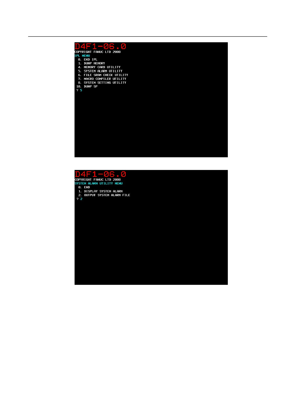
2.
On the IPL monitor screen, enter 5 to select "5. SYSTEM ALARM UTILITY".
- 393 -
10.TROUBLESHOOTING
B-64305EN/03
3.
Enter 2 to select "2. OUTPUT SYSTEM ALARM FILE".
4.
If the IPL monitor is executed on the system alarm screen, enter 2 to select "2. OUTPUT SYSTEM
ALARM FILE FROM DRAM".
If the power is turned off, enter
1 to select "1. OUTPUT SYSTEM ALARM FILE FROM
FILE-RAM".
- 394 -
B-64305EN/03
10.TROUBLESHOOTING
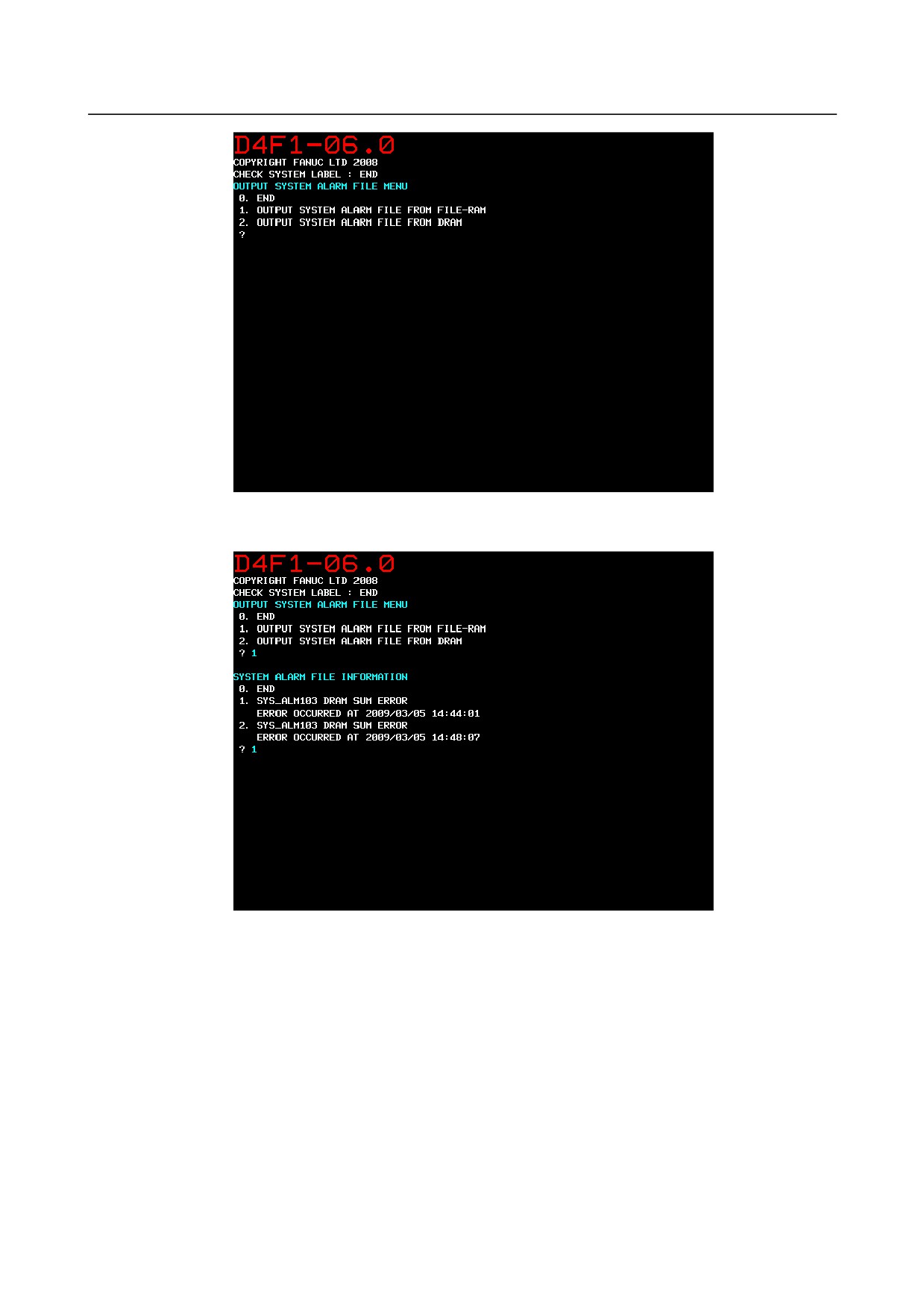
5.
If 1 is selected in step 4, a list of saved system alarms is displayed. Enter the number of a file to be
output.
- 395 -
10.TROUBLESHOOTING
B-64305EN/03
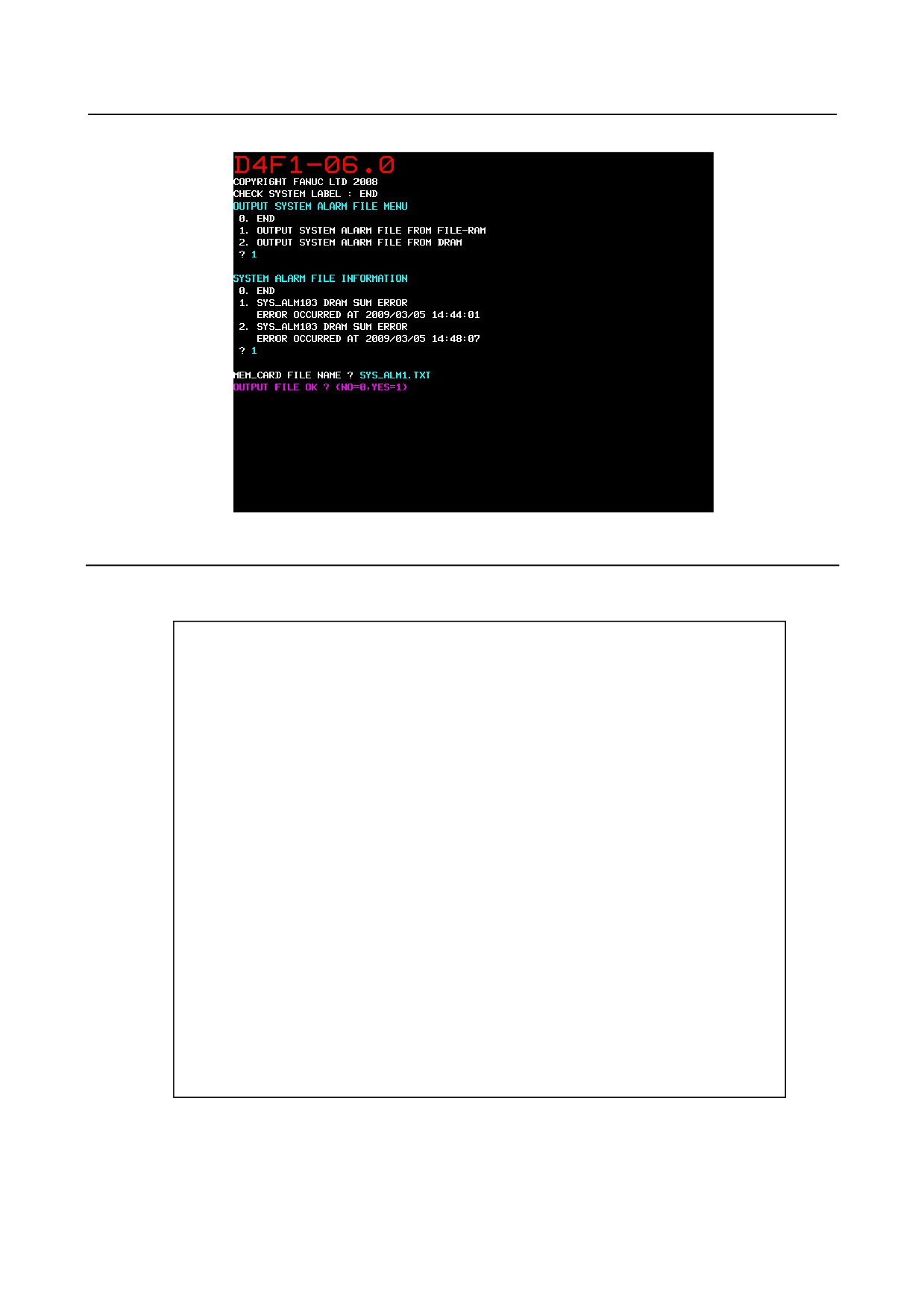
6.
Enter the name of a file to be output to the memory card and output the file.
10.25.3 System Alarms Detected by Hardware
System alarm 400 and subsequent system alarms indicate errors detected by hardware.
The basic screen configuration is shown below:
(1)D4F1 ー 01.0
(2)
SYS_ALM401 EXTERNAL BUS INVALID ADDRESS
(3)
MAIN BOARD
(4)
2008/04/22 17:09:53
(5)
PROGRAM COUNTER
: 1000B52CH
|
ACT TASK
: 01000010H
|
ACCESS ADDRESS
:
-
|
ACCESS DATA
:
-
↓
ACCESS OPERATION :
-
(6)
BUS MASTER PCB
: ETC
|
+--+----------+-----------------------------------------------------+
|
02 ETC
03012003 22110000 80010000 00000000 00010000 00000000
|
FFFFFFFF FFFFFFFF 68C08216 70FE0000 00000000 00000000
|
00000000 00000000 00000000 00000000 00000000
|
|
BUS SLAVE PCB
: CPU
|
+--+----------+-----------------------------------------------------+
|
00 CPU
02071004 20100000 00000000 00000000 00000000 00000000
|
FFFFFFFF FFFFFFFF 10B0FC00 CFF90001 68C30061 82160010
|
000000F0 00000000 00010000 00000000 00000000
|
|
INFORMATION REGISTER
|
+--+----------+-----------------------------------------------------+
↓
02 ETC
00000000 00000000 00000000 00000000
PAGE UP OR DOWN (PAGE
1/8)
[Description of the message screen]
(1): Device name, and series and edition of CNC system software
(2): System alarm number and error message
(3): Most possibly faulty component
(4): Date and time when the error occurred
- 396 -

B-64305EN/03
10.TROUBLESHOOTING
(5): Software error and other information when the error occurred
(6): Bus information when the error occurred
Item (3) indicates the most possibly faulty component. Mainly, check the
component to see whether it is defective.
Information on the system alarm screen can be output as a text file through the PCMCIA port of the
display unit. Contact the FANUC service department after obtaining the information.
For the method of outputting it, see Section 10.25.2, "Operations on the System Alarm Screen".
Main errors are described on the following pages.
System Alarm 401 (EXTERNAL BUS INVALID ADDRESS)
D4F1 ー 01.0
SYS_ALM401 EXTERNAL BUS INVALID ADDRESS
MAIN BOARD
2008/04/21 20:34:16
PROGRAM COUNTER
: 1000B52CH
ACT TASK
: 01000010H
ACCESS ADDRESS
:
-
ACCESS DATA
:
-
ACCESS OPERATION :
-
BUS MASTER PCB
: ETC
+--+----------+-----------------------------------------------------+
02 ETC
03012003 22110000 80010000 00000000 00010000 00000000
FFFFFFFF FFFFFFFF 68C08216 70FE0000 00000000 00000000
00000000 00000000 00000000 00000000 00000000
BUS SLAVE PCB
: CPU
+--+----------+-----------------------------------------------------+
00 CPU
02071004 20100000 00000000 00000000 00000000 00000000
FFFFFFFF FFFFFFFF 10B0FC00 CFF90001 68C30061 82160010
000000F0 00000000 00010000 00000000 00000000
INFORMATION REGISTER
+--+----------+-----------------------------------------------------+
02 ETC
00000000 00000000 00000000 00000000
PAGE UP OR DOWN (PAGE
1/8)
Description
A problem occurred on a CNC bus.
Causes
The printed circuit board may be defective or external noise may affect the bus.
Countermeasures
Replace the displayed most possibly faulty component. In addition, the main board, or the part shown as
“BUS MASTER PCB” or “BUS SLAVE PCB” displayed on the system alarm screen may be defective.
This error may also be caused by external noise.
Check whether there is a noise origin around the machine and whether the machine is grounded properly.
- 397 -

10.TROUBLESHOOTING
B-64305EN/03
System Alarm 403 (S-BUS TIME OUT ERROR)
D4F1 ー 01.0
SYS_ALM403 S-BUS TIME OUT ERROR
MAIN BOARD
2008/04/21 21:24:12
PROGRAM COUNTER
: 102FD028H
ACT TASK
: 01000010H
ACCESS ADDRESS
:
-
ACCESS DATA
:
-
ACCESS OPERATION :
-
BUS MASTER PCB
: CPU
+--+----------+-----------------------------------------------------+
00 CPU
02071004 20100000 00000000 00000000 00040000 00000000
FFFFFFFF FFFFFFFF 00A88820 C3F90000 00000000 00000000
00000000 00000000 00000000 00000000 00000000
BUS SLAVE PCB
: ETC
+--+----------+-----------------------------------------------------+
02 ETC
03012003 22110000 A0000000 00000000 00000000 00000000
FFFFFFFF FFFFFFFF 00A88820 C3010000 00000000 00000000
00000000 00000000 00000000 00000000 00000000
INFORMATION REGISTER
+--+----------+-----------------------------------------------------+
02 ETC
00000000 00000000 00000000 00000000
PAGE UP OR DOWN (PAGE
1/8)
Description
A problem occurred on a CNC bus.
Causes
The printed circuit board may be defective.
Countermeasures
Replace the displayed most possibly faulty component. In addition, the main board, or the part shown as
“BUS MASTER PCB” or “BUS SLAVE PCB” displayed on the system alarm screen may be defective.
- 398 -

B-64305EN/03
10.TROUBLESHOOTING
System Alarm 404 (ECC UNCORRECTABLE ERROR)
D4F1 ー 01.0
SYS_ALM404 ECC UNCORRECTABLE ERROR
MAIN BOARD
2008/04/22 17:09:53
PROGRAM COUNTER
: 100DB2E0H
ACT TASK
: 0100FFFBH
ACCESS ADDRESS
:
-
ACCESS DATA
:
-
ACCESS OPERATION :
-
BUS MASTER PCB
: ETC
+--+----------+-----------------------------------------------------+
02 ETC
03012003 22110000 80010000 00000000 00080000 00000000
FFFFFFFF FFFFFFFF 68C08216 70FE0000 00000000 00000000
00000000 00000000 00000000 00000000 00000000
BUS SLAVE PCB
: CPU
+--+----------+-----------------------------------------------------+
00 CPU
02071004 20100000 00000000 00000000 00000000 00000000
FFFFFFFF FFFFFFFF 10B0FC00 CFF90001 68C30061 82160010
000000F0 00000000 00010000 00000000 00000000
INFORMATION REGISTER
+--+----------+-----------------------------------------------------+
02 ETC
00000000 00000000 00000000 00000000
PAGE UP OR DOWN (PAGE
1/8)
Description
A problem occurred on a CNC bus.
Causes
The printed circuit board may be defective or external noise may affect the bus.
Countermeasures
Replace the displayed most possibly faulty component.
This error may also be caused by external noise.
Check whether there is a noise origin around the machine and whether the machine is grounded properly.
- 399 -
10.TROUBLESHOOTING
B-64305EN/03
System Alarm 500 (SRAM DATA ERROR(SRAM MODULE))
D4F01 ー 1.0
SYS_ALM500 SRAM DATA ERROR(SRAM MODULE)
FROM/SRAM MODULE
2008/04/21 21:26:52
PROGRAM COUNTER
: 1000C0C4H
ACT TASK
: 30000001H
ACCESS ADDRESS
:
-
ACCESS DATA
:
-
ACCESS OPERATION :
-
BUS MASTER PCB
: ETC
+--+----------+-----------------------------------------------------+
02 ETC
03012003 22110000 A0000000 00000000 00002000 00000000
FFFFFFFF FFFFFFFF 822088A3 C3FE0001 00000000 00000000
00000000 00000000 00000000 00000000 00000000
BUS SLAVE PCB
: ETC
+--+----------+-----------------------------------------------------+
02 ETC
03012003 22110000 A0000000 00000000 00004000 00000000
FFFFFFFF FFFFFFFF 822088A3 C3FE0001 00000000 00000000
00000000 00000000 00000000 00000000 00000000
INFORMATION REGISTER
+--+----------+-----------------------------------------------------+
02 ETC
00000000 00000000 00000000 00000000
PAGE UP OR DOWN (PAGE
1/8)
Description
Data could not be transferred to the SRAM on the FROM/SRAM module normally.
Causes
The module may be defective or the connector may not be connected securely.
Countermeasures
First, act SRAM all clear operation or restore SRAM backup data, and confirm this alarm will be
dissolved. If this alarm is dissolved with this operation, a temporary destruction of SRAM data is
supposable cause.
If this alarm does not dissolve by above operation, replace the FROM/SRAM module.
If the machine does not recover after replacement of FROM/SRAM module, replace the main board.
- 400 -

B-64305EN/03
10.TROUBLESHOOTING
System Alarm 502 (NOISE ON POWER SUPPLY)
D4F1 ー 01.0
SYS_ALM502 NOISE ON POWER SUPLY
POWER SUPPLY
2008/04/21 21:26:52
PROGRAM COUNTER
: 1000C0C4H
ACT TASK
: 30000001H
ACCESS ADDRESS
:
-
ACCESS DATA
:
-
ACCESS OPERATION :
-
BUS MASTER PCB
: ETC
+--+----------+-----------------------------------------------------+
02 ETC
03012003 22110000 A0000000 00000000 00001000 00000000
FFFFFFFF FFFFFFFF 822088A3 C3FE0001 00000000 00000000
00000000 00000000 00000000 00000000 00000000
BUS SLAVE PCB
: ETC
+--+----------+-----------------------------------------------------+
02 ETC
03012003 22110000 A0000000 00000000 00004000 00000000
FFFFFFFF FFFFFFFF 822088A3 C3FE0001 00000000 00000000
00000000 00000000 00000000 00000000 00000000
INFORMATION REGISTER
+--+----------+-----------------------------------------------------+
02 ETC
00000000 00000000 00000000 00000000
PAGE UP OR DOWN (PAGE
1/8)
Description
Noise or an instantaneous power failure occurred in the CNC power supply.
Causes
A power fault occurs.
Countermeasures
Find and remove the cause of the error.
This error may damage SRAM data.
- 401 -

10.TROUBLESHOOTING
B-64305EN/03
System Alarm 503 (ABNORMAL POWER SUPPLY)
D4F1 ー 01.0
SYS_ALM503 NOISE ON POWER SUPLY
ABNORMAL POWER SUPPLY
2008/04/21 21:26:52
PROGRAM COUNTER
: 1000C0C4H
ACT TASK
: 30000001H
ACCESS ADDRESS
:
-
ACCESS DATA
:
-
ACCESS OPERATION :
-
BUS MASTER PCB
: ETC
+--+----------+-----------------------------------------------------+
02 ETC
03012003 22110000 A0000000 00000000 00001000 00000000
FFFFFFFF FFFFFFFF 822088A3 C3FE0001 00000000 00000000
00000000 00000000 00000000 00000000 00000000
BUS SLAVE PCB
: ETC
+--+----------+-----------------------------------------------------+
02 ETC
03012003 22110000 A0000000 00000000 00004000 00000000
FFFFFFFF FFFFFFFF 822088A3 C3FE0001 00000000 00000000
00000000 00000000 00000000 00000000 00000000
INFORMATION REGISTER
+--+----------+-----------------------------------------------------+
02 ETC
00000000 00000000 00000000 00000000
PAGE UP OR DOWN (PAGE
1/8)
Description
A fault occurred in the power supply on the main board.
Causes
The power supply is defective.
Countermeasures
Replace the power supply.
10.25.4 System Alarms 114 to 137 (Alarms on the FSSB)
Causes
An alarm was detected on the FSSB.
NOTE
When the message is followed by /LINE1, it indicates the number (COP10A-1) of
the optical connector on the axis card.
- 402 -

B-64305EN/03
10.TROUBLESHOOTING
SYS_ALM114 FSSB DISCONNECTION
114: Communication between the axis card and 1st servo
(MAIN -> AMP1) /LINE1
amplifier failed.
SYS_ALM115 FSSB DISCONNECTION
115: Communication between the axis card and 1st
(MAIN -> PULSE MODULE1) /LINE1
separate detector interface unit failed.
SYS_ALM116 FSSB DISCONNECTION
116: Communication between the nth and mth servo
(AMPn -> AMPm) /LINE1
amplifiers failed.
SYS_ALM117 FSSB DISCONNECTION
117: Communication between the nth servo amplifier and
(AMPn -> PULSE MODULEm) /LINE1
mth separate detector interface unit failed.
SYS_ALM118 FSSB DISCONNECTION
118: Communication between the nth separate detector
(PULSE MODULEn -> AMPm) /LINE1
interface unit and mth servo amplifier failed.
SYS_ALM119 FSSB DISCONNECTION
119: Communication between the 1st and 2nd separate
(PULSE MODULE1 -> PULSE MODULE2)
detector interface units failed.
/LINE1
SYS_ALM120 FSSB DISCONNECTION
120: Communication between the axis card and 1st servo
(MAIN <- AMP1) /LINE1
amplifier failed.
SYS_ALM121 FSSB DISCONNECTION
121: Communication between the axis card and 1st
(MAIN <- PULSE MODULE1) /LINE1
separate detector interface unit failed.
SYS_ALM122 FSSB DISCONNECTION
122: Communication between the nth and mth servo
(AMPn <- AMPm) /LINE1
amplifiers failed.
SYS_ALM123 FSSB DISCONNECTION
123: Communication between the nth servo amplifier and
(AMPn <- PULSE MODULEm) /LINE1
mth separate detector interface unit failed.
SYS_ALM124 FSSB DISCONNECTION
124: Communication between the nth separate detector
(PULSE MODULEn <- AMPm) /LINE1
interface unit and mth servo amplifier failed.
SYS_ALM125 FSSB DISCONNECTION
125: Communication between the 1st and 2nd separate
(PULSE MODULE1 <- PULSE MODULE2)
detector interface units failed.
/LINE1
Replace the optical cable for the relevant connection. If
the alarm persists, replace the axis card, corresponding
servo amplifier, and corresponding separate detector
interface unit.
When the arrow points to the left, a power fault may occur
in the servo amplifier or separate detector interface unit at
the base of the arrow. Check the +24 V power supply
input to the relevant unit and the +5 V power supply for the
pulse coder output from the relevant unit for an error such
as a ground fault.
SYS_ALM126 FSSB INTERNAL DISCONNECTION
126: Internal communication in the nth servo amplifier
(AMPn) ->
/LINE1
failed.
SYS_ALM127 FSSB INTERNAL DISCONNECTION
127: Internal communication in the nth servo amplifier
(AMPn) <-
/LINE1
failed.
Replace the relevant servo amplifier.
SYS_ALM129 ABNORMAL POWER SUPPLY
129: A fault was detected in the power supply of the nth
(SERVO:AMPn) /LINE1
servo amplifier.
SYS_ALM130 ABNORMAL POWER SUPPLY
130: A fault was detected in the power supply of the nth
(SERVO:PULSE MODULEn) /LINE1
separate detector interface unit.
Check the power supply of the relevant servo amplifier or
separate detector interface unit.
- 403 -