FANUC Series 0i-MODEL D, FANUC Series 0i Mate-MODEL D. MAINTENANCE MANUAL - page 3
1.DISPLAY AND OPERATION
B-64305EN/03
When [H-DOBL] or [H-HALF] soft key is pressed, the length of the time axis on one screen is extended
or reduced, respectively.
When a waveform cannot fit in one screen, the time axis can be moved by pressing [←TIME] or
[TIME→] soft key.
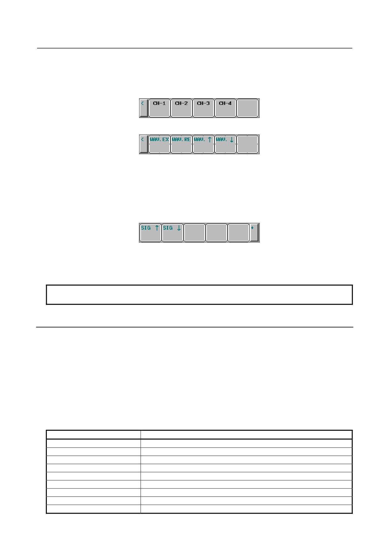
Furthermore, pressing [CH-1], [CH-2], [CH-3], or [CH-4] soft key, following submenu appears.
When [WAV.EX] or [WAV.RE] soft key is pressed, the length of the time axis on one screen is extended
or reduced, respectively. The graduation unit on the horizontal axis, which is a parameter, also changes
automatically.
The graduation unit changes from 1 to 2 to 5 to 10 to 20 to 50 to 100, and so on.
When [WAV.↑] or [WAV.↓] soft key is pressed, each waveform of servo and spindle data can be moved
upward or downward.
Displaying signal data
Up to 32 signals can be measured at the same time. Up to nine signals can be displayed at the same time
if only signal data is displayed, or up to four signals can be displayed if signal data is displayed over
waveforms.
When [SIG.↑] or [SIG.↓] soft key is pressed, the currently displayed signals are changed.
NOTE
Signal data cannot be moved.
1.6.4
Outputting Data
Waveform diagnosis data can be output to an input/output device.
Specifying a format
When outputting data, you can select one of the two formats, which are the FS0i-C compatible format and
the FS0i-D. If bit 0 (IOF) of parameter No. 10600 is set to 0, the FS0i-D format is selected; if bit 0
(IOF) of parameter No. 10600 is set to 1, the FS0i-C compatible format is selected.
Output format
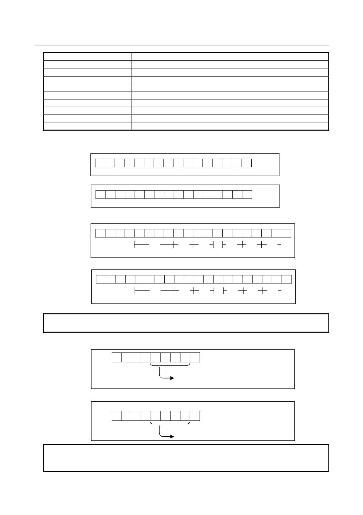
Traced data is output as a text file with the following format:
-
Identifiers
Identifier word (T)
Meaning
T0/T1
Header
T60
Servo positional deviation
T61
Servo pulses after distribution
T62
Servo torque
T63
Actual servo speed
T64
Servo current command value
T65
Servo heat simulation data
T68
Measurement item
T69
Date and time (start of measurement)
- 44 -
B-64305EN/03
1.DISPLAY AND OPERATION
Identifier word (T)
Meaning
T70
Servo pulses after acceleration/deceleration
T75
Composite speed of all axes
T80
Spindle speed
T81
Spindle load meter
T82
Difference in spindle-converted positional deviation
T90
Measurement period (waveform)
T91
Measurement period (signal)
T92
Date and time (end of measurement)
T98
Signal data
(1)
Header
FS0i-D format
T
1
C
W
A
V
E
D
I
A
G
N
O
S
;
FS0i-C compatible format
T
0
C
W
A
V
E
D
I
A
G
N
O
S
;
(2)
Date and time of start/end of tracing
-
Starting date and time
T
6
9
D
,
;
Year
Month
Day
Hour
Min
Sec
-
Ending date and time
T
9
2
D
*
*
*
,
*
*
*
;
Month
Day
Hour
Min
Year
Sec
NOTE
The ending date and time is output only in the FS0i-D format.
(3) Waveform sampling cycle
T
9
0
D
;
Waveform sampling cycle
(4) Signal sampling cycle
T
9
1
D
*
*
;
Signal sampling perio
NOTE
The waveform sampling cycle and signal sampling cycle are output only in the
FS0i-D format.
- 45 -
1.DISPLAY AND OPERATION
B-64305EN/03
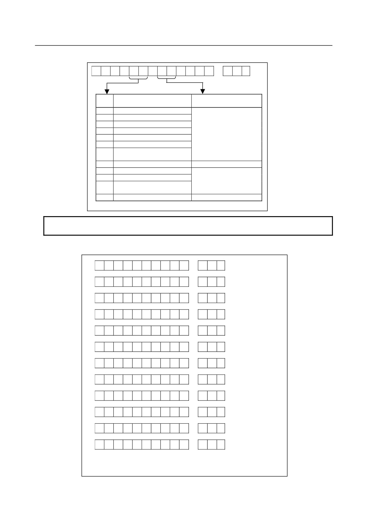
(5) Selection items
T
6
8
P
D
,
,
~
;
Measurement item
Axis No./path
No./signal address
P0
Servo positional deviation
Controlled axis number
P1
Servo pulses after distribution
(1 to 8)
P2
Servo torque
P3
Actual servo speed
P4
Servo current command value
P5
Servo heat simulation data
P6
Servo pulses after
acceleration/deceleration
P10
Composite speed of all axes
Path number (1 to 2)
P20
Spindle speed
Controlled spindle
P21
Spindle load meter
number
P22
Difference in spindle-convert
(1 to 3)
positional deviation
P30
Signal
Signal address
NOTE
Items P6 to P30 are output only in the FS0i-D format.
(6)
Waveform diagnosis data
T
6
0
D
,
,
~
;
T
6
1
D
,
,
~
;
T
6
2
D
,
,
~
;
T
6
3
D
,
,
~
;
T
6
4
D
,
,
~
;
T
6
5
D
,
,
~
;
T
7
0
D
,
,
~
;
T
7
5
D
,
,
~
;
T
8
0
D
,
,
~
;
T
8
1
D
,
,
~
;
T
8
2
D
,
,
~
;
T
9
8
D
*
,
,
~
*
;
D** ~ ** : Waveform diagnosis data × No. of axes/No. of
paths/No. of spindles/No. of signals
- 46 -
B-64305EN/03
1.DISPLAY AND OPERATION
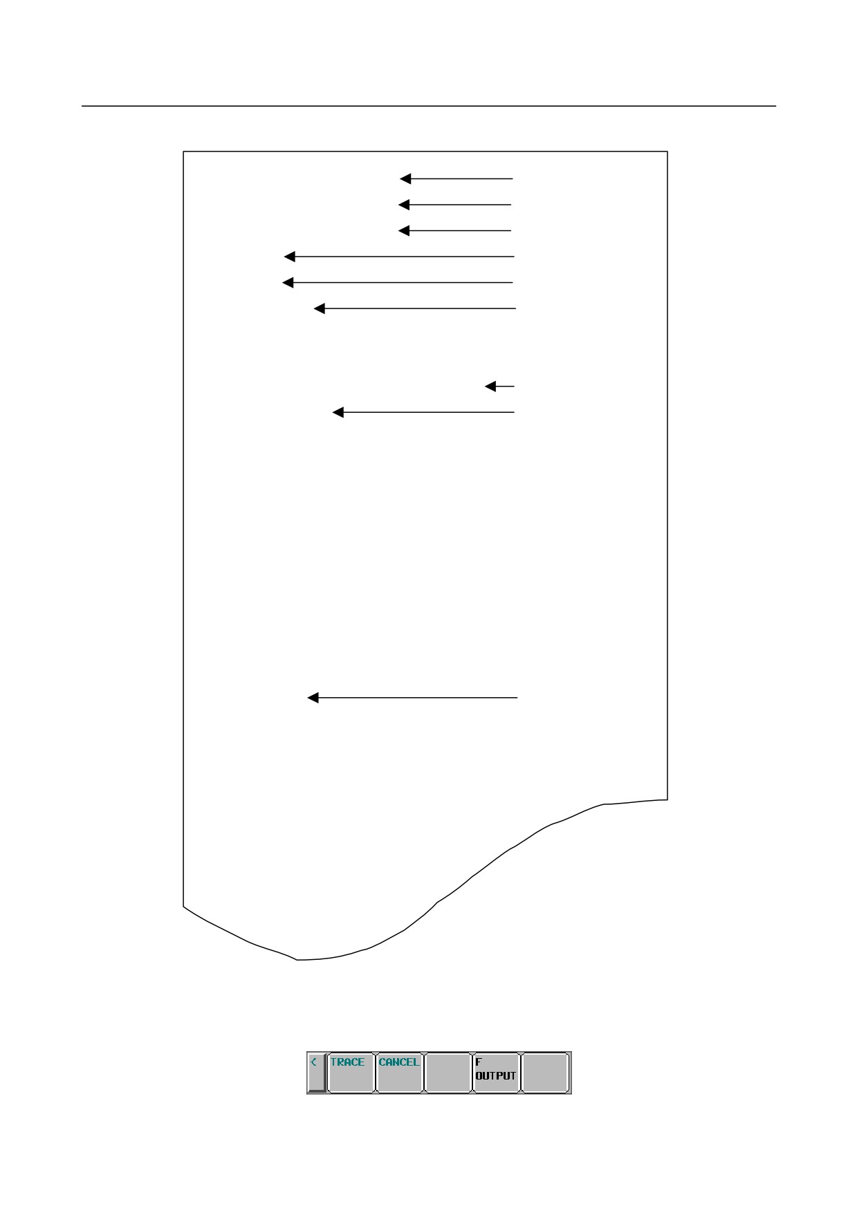
Blocks are output in the following order:
Header
(FS0i-C compatible/FS0i-D format)
Date and time (start of measurement)
(FS0i-C compatible/FS0i-D format)
Date and time (end of measurement)
(FS0i-D format only)
Waveform measurement period
(FS0i-D format only)
Signal measurement period
(FS0i-D format only)
Selection item
(FS0i-C compatible/FS0i-D format)
Waveform diagnosis data
(FS0i-C compatible/FS0i-D format)
NOTE
Signal data of waveform diagnosis data is output after all waveform data is
output.
- 47 -
1.DISPLAY AND OPERATION
B-64305EN/03
-
Sample file (FS0i-D format)
T01WAVE DIAGNOSE
Header
T69D20040101,120125
Start time
T92D20040101,120130
End time
T90D2
Waveform period
T91D4
Signal period
T68P0D1,2
Measurement item/axis
T68P4D1
T68P10D1
T68P30DG0010.4,G0010.5,G0010.6
Measurement item/signal
T60D643,6420
Waveform data
T64D270
T75D1855
T60D673,6451
T64D265
T75D1855
T60D702,6480
T64D268
T75D1855
:
T75D1855
T98D0,0,1
Signal data
T98D0,0,1
T98D0,0,1
:
Outputting a file
1
Display the waveform diagnosis graph screen.
2
When the [(OPRT)] soft key is pressed, soft keys are displayed in the following operation selection
state:
3
Change the mode to the EDIT mode.
- 48 -
B-64305EN/03
1.DISPLAY AND OPERATION
4
Enter a file name in the key-in buffer, and press the [F OUTPUT] soft key. If no file name is input,
the file name is assumed to be WAVE-DGN.TXT by default.
5
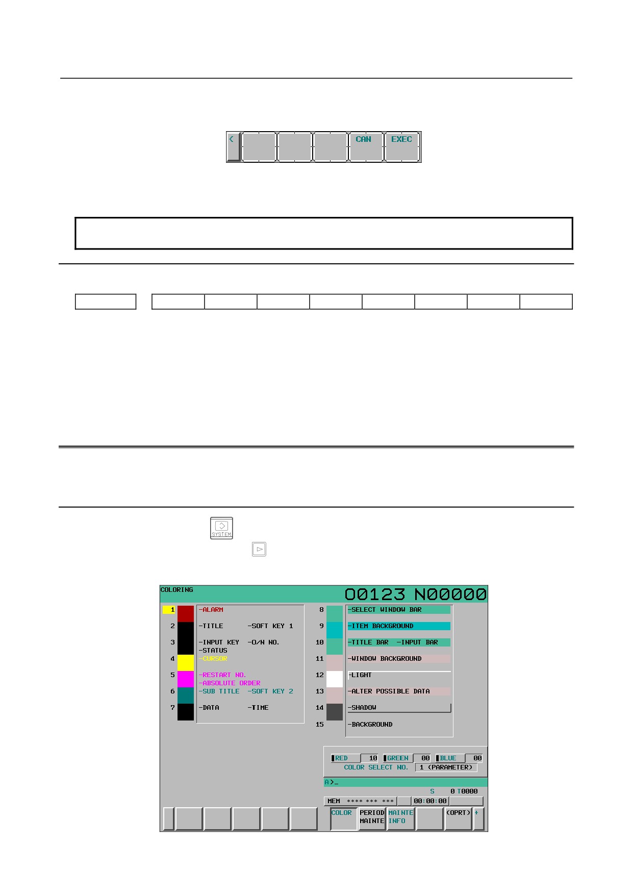
Press the [EXEC] soft key shown below to start outputting data:
6
When data output ends, or when the [CAN] soft key is pressed, the initial operation selection state is
restored.
NOTE
While data is being traced, data output is not allowed.
Parameter
#7
#6
#5
#4
#3
#2
#1
#0
10600
IOF
[Input type] Parameter input
[Type of data] Bit
#0 IOF The output format used for waveform diagnosis is:
0: FS0i-D format.
1: FS0i-C compatible format.
1.7
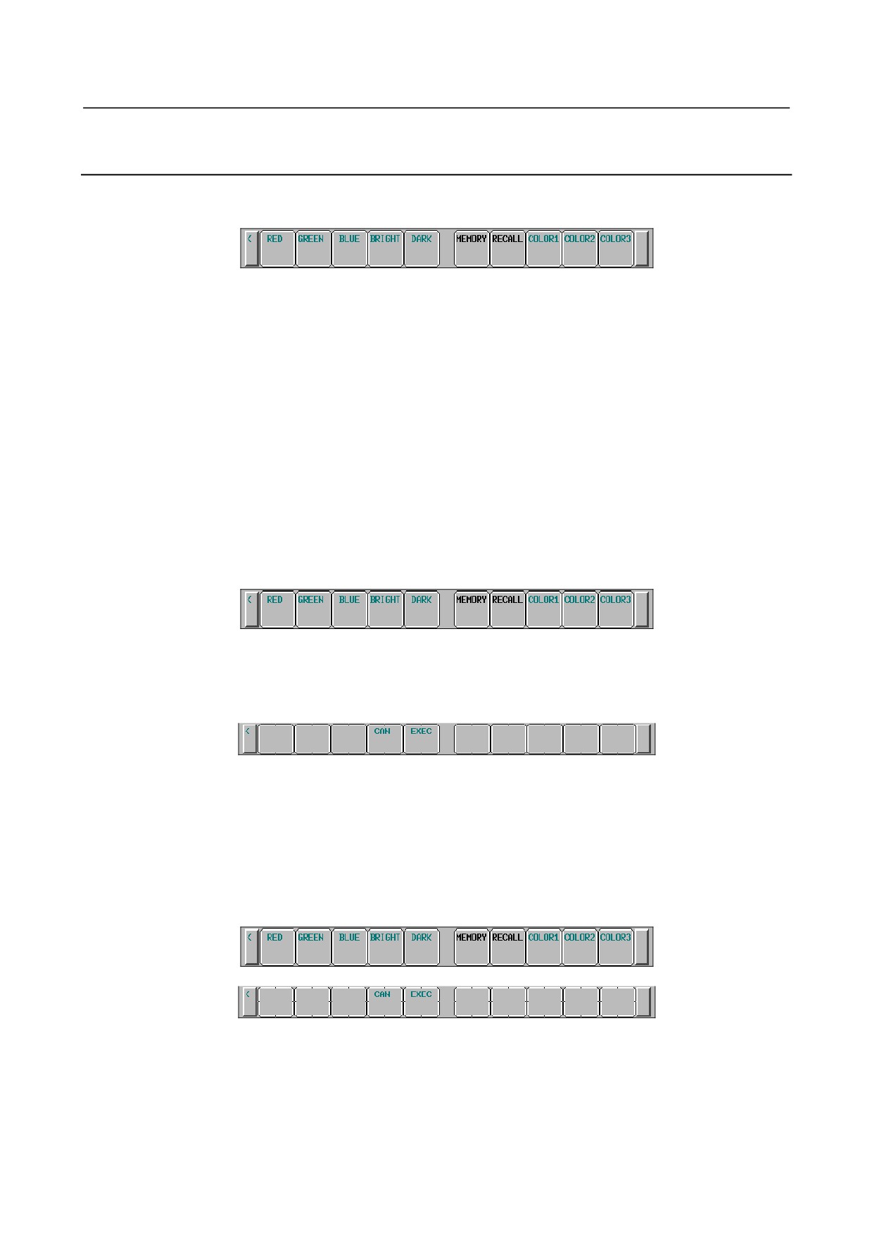
COLOR SETTING SCREEN
The coloring screen can be used to specify screen coloring.
1.7.1
Screen Display
1
Press the function key
2
Press the continuous menu key
several times until the [COLOR] soft key is displayed.
3
Pressing the [COLOR] soft key displays the color setting screen.
- 49 -
1.DISPLAY AND OPERATION
B-64305EN/03
1.7.2
Operations for Color Setting
Modification to color settings (color palette values)
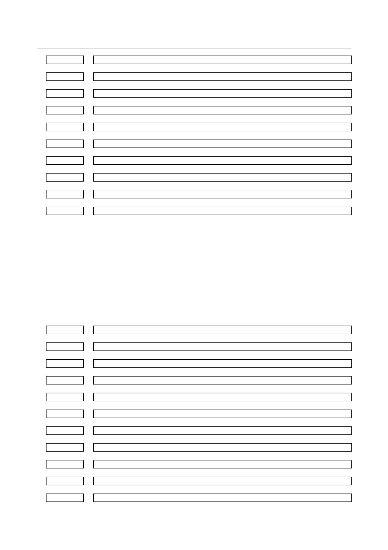
1
Pressing the [(OPRT)] soft key displays the following operation soft keys:
2
Move the cursor to a color number whose color palette values are to be modified.
The current color palette values of the individual color elements are displayed.
3
Select a color element to be modified, with the [RED], [GREEN], or [BLUE] operation soft key.
Multiple color elements can be selected at a time.
Each of the [RED], [GREEN], and [BLUE] soft keys toggles between selection and deselection each
time the soft key is pressed.
(The [RED], [GREEN], and [BLUE] soft keys, when not displayed, can be displayed by pressing the
rightmost soft key.)
4
By pressing the [BRIGHT] or [DARK] operation soft key, modify the brightness of the selected
color element.
Storing color settings (color palette values)
Set color palette values can be stored.
1
Select a storage area by pressing the [COLOR1], [COLOR2], or [COLOR3] operation soft key.
(The [COLOR1], [COLOR2], and [COLOR3] soft keys, when not displayed, can be displayed by
pressing the rightmost soft key.)
Color 1: Standard color data parameters Nos. 6581 to 6595
Color 2: Parameters Nos. 10421 to 10435
Color 3: Parameters Nos. 10461 to 10475
2
Press the [MEMORY] operation soft key. The following operation soft keys are displayed:
3
Press the [EXEC] operation soft key. The current color palette values are stored in the selected area.
Pressing the [CAN] operation soft key or the leftmost key does not store the current color palette
values.
Calling color settings (color palette values)
1
Select an area for storing color palette values by pressing the [COLOR1], [COLOR2], or [COLOR3]
operation soft key.
(The [COLOR1], [COLOR2], and [COLOR3] soft keys, when not displayed, can be displayed by
pressing the rightmost soft key.)
2
Press the [RECALL] operation soft key. The following operation soft keys are displayed:
3
Press the [EXEC] operation soft key. Color palette values are called from the selected area for
modification to the color settings. This operation is invalid if no color palette values are stored.
Pressing the [CANCEL] operation soft key or the leftmost key does not call color palette values.
- 50 -

B-64305EN/03
1.DISPLAY AND OPERATION
1.7.3
Parameter
6581
RGB value of color palette 1
6582
RGB value of color palette 2
6583
RGB value of color palette 3
6584
RGB value of color palette 4
6585
RGB value of color palette 5
6586
RGB value of color palette 6
6587
RGB value of color palette 7
6588
RGB value of color palette 8
6589
RGB value of color palette 9
6590
RGB value of color palette 10
6591
RGB value of color palette 11
6592
RGB value of color palette 12
6593
RGB value of color palette 13
6594
RGB value of color palette 14
6595
RGB value of color palette 15
[Input type] Parameter input
[Data type] 2-word
[Valid data range] 0 to 151515
Each of these parameters sets the RGB value of each color palette by specifying a 6-digit
number as described below.
rrggbb: 6-digit number (rr: red data, gg: green data, bb: blue data)
The valid data range of each color is 0 to 15 (same as the tone levels on the color setting
screen). When a number equal to or greater than 16 is specified, the specification of 15 is
assumed.
Example)
When the tone level of a color is: red:1 green:2, blue:3, set 10203 in the parameter.
10421
RGB value of color palette 1 for color set 2
10422
RGB value of color palette 2 for color set 2
10423
RGB value of color palette 3 for color set 2
10424
RGB value of color palette 4 for color set 2
10425
RGB value of color palette 5 for color set 2
- 51 -
1.DISPLAY AND OPERATION
B-64305EN/03
10426
RGB value of color palette 6 for color set 2
10427
RGB value of color palette 7 for color set 2
10428
RGB value of color palette 8 for color set 2
10429
RGB value of color palette 9 for color set 2
10430
RGB value of color palette 10 for color set 2
10431
RGB value of color palette 11 for color set 2
10432
RGB value of color palette 12 for color set 2
10433
RGB value of color palette 13 for color set 2
10434
RGB value of color palette 14 for color set 2
10435
RGB value of color palette 15 for color set 2
[Input type] Parameter input
[Data type] 2-word
[Valid data range] 0 to 151515
Each of these parameters sets the RGB value of each color palette by specifying a 6-digit
number as described below.
rrggbb: 6-digit number (rr: red data, gg: green data, bb: blue data)
The valid data range of each color is 0 to 15 (same as the tone levels on the color setting
screen). When a number equal to or greater than 16 is specified, the specification of 15 is
assumed.
Example)
When the tone level of a color is: red:1 green:2, blue:3, set 10203 in the parameter.
10461
RGB value of color palette 1 for color set 3
10462
RGB value of color palette 2 for color set 3
10463
RGB value of color palette 3 for color set 3
10464
RGB value of color palette 4 for color set 3
10465
RGB value of color palette 5 for color set 3
10466
RGB value of color palette 6 for color set 3
10467
RGB value of color palette 7 for color set 3
10468
RGB value of color palette 8 for color set 3
10469
RGB value of color palette 9 for color set 3
10470
RGB value of color palette 10 for color set 3
10471
RGB value of color palette 11 for color set 3
- 52 -
B-64305EN/03
1.DISPLAY AND OPERATION
10472
RGB value of color palette 12 for color set 3
10473
RGB value of color palette 13 for color set 3
10474
RGB value of color palette 14 for color set 3
10475
RGB value of color palette 15 for color set 3
[Input type] Parameter input
[Data type] 2-word
[Valid data range] 0 to 151515
Each of these parameters sets the RGB value of each color palette by specifying a 6-digit
number as described below.
rrggbb: 6-digit number (rr: red data, gg: green data, bb: blue data)
The valid data range of each color is 0 to 15 (same as the tone levels on the color setting
screen). When a number equal to or greater than 16 is specified, the specification of 15 is
assumed.
Example)
When the tone level of a color is: red:1 green:2, blue:3, set 10203 in the parameter.
1.7.4
Notes
(1) When the power is turned on, color 1 (parameter) is specified for the screen. If no data is stored in
color 1, the default color is used.
(2) Do not use MDI key inputs directly to change the color data parameter. To change it, do so by
performing storage operation on the coloring screen.
1.8
POWER MATE CNC MANAGER FUNCTION
When the I/O Link Option for the FANUC servo unit βi series (called I/O Link βi below) is used for CNC
additional axes (slaves), the Power Mate CNC manager function can be used to display and set up various
types of data of these slaves on the CNC.
The Power Mate CNC manager function enables the following display and setting operations:
(1) Current position display (absolute/machine coordinates)
(2) Parameter display and setting
(3) Alarm display
(4) Diagnosis data display
(5) System configuration screen display
Up to eight slaves can be connected to each I/O Link channel.
1.8.1
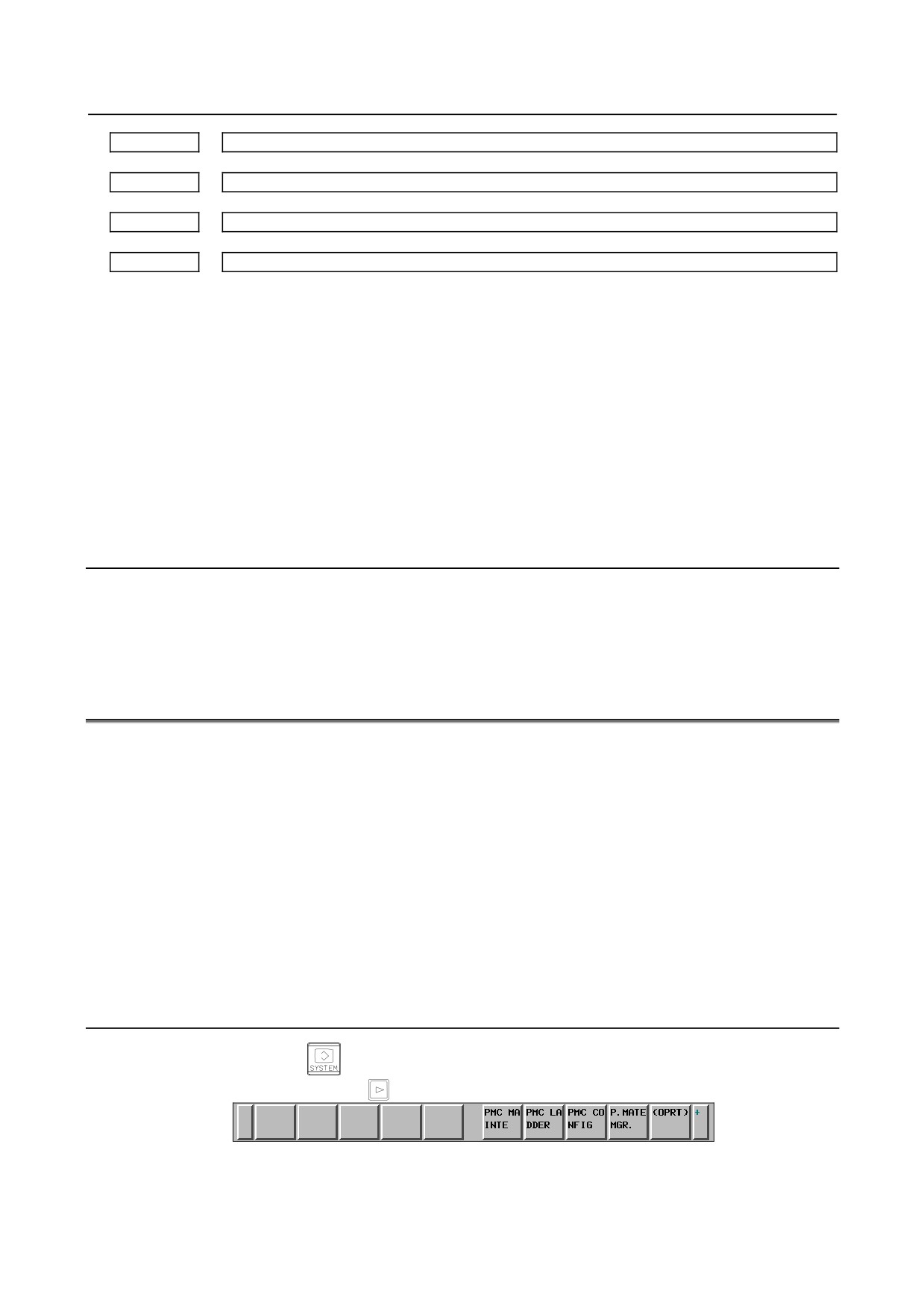
Screen Display
1
Press the function key
2
Press the continuous menu key
several times until the [P.MATE MGR.] soft key is displayed.
3
Pressing the [P.MATE MGR.] soft key displays the absolute coordinate screen, which is the initial
screen of the Power Mate CNC manager. On this screen, you can select each of the following
items by pressing the corresponding soft key:
[ABSOLUTE]
: Absolute coordinate display (current position display screen)
- 53 -
1.DISPLAY AND OPERATION
B-64305EN/03
[MACHINE]
: Machine coordinate display (current position display screen)
[PARAMETER]
: Parameter screen
[MESSAGE]
: Alarm screen
[DIAGNOSIS]
: Diagnosis screen
[SYSTEM CONFIG] : System configuration screen
To select another function after one of the functions listed above is selected, press the return menu
key
until the soft keys
appear as shown above. Then, select the desired function.
once or
4
To terminate the Power Mate CNC manager function, first push the return menu key
twice. The CNC system soft
key is displayed. Pressing this soft key lets you exit Power Mate
CNC manager.
Alternatively, pressing an MDI function key (such as
,
, or
) terminates the Power
Mate CNC manager function.
Selecting a slave
When slaves are connected to multiple I/O Link channels, pressing [NEXT CH.] or [PREV. CH.] soft key
displayed by pressing the [(OPRT)] soft key changes the displayed channel.
In the upper section of the screen, the following information items are displayed for the connected slaves
(up to eight slaves):
-
I/O Link group number (0 to 15)
-
Alarm status
The cursor is positioned at the number of the slave for which to display information (active slave).
When multiple slaves are connected, pressing the [NEXT SLAVE] or [PREV. SLAVE] soft key changes
the active slave.
You can display the slave status and select a slave on any screen of the Power Mate CNC manager
function.
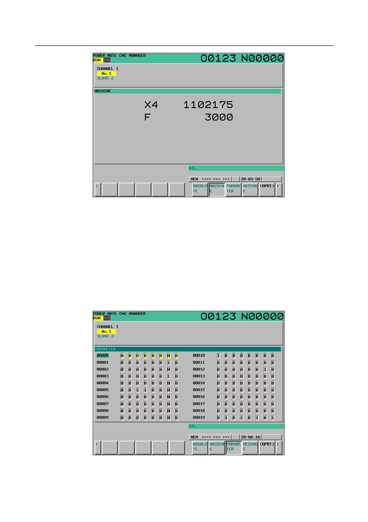
Current position display screen
The current position display screen displays the current position and actual speed of the slave.
The following current position data is displayed:
Absolute coordinate (current position in the absolute coordinate system)
Machine coordinate (current position in the machine coordinate system)
-
Display method
Press soft key [ABSOLUTE] to display the absolute coordinate screen.
Press soft key [MACHINE] to display the machine coordinate screen.
- 54 -
B-64305EN/03
1.DISPLAY AND OPERATION
Power Mate CNC manager: Machine coordinate screen
Axis name display
Parameter Nos. 0024 and 0025 on the I/O Link ȕi side are used to set axis names. Up to two characters
can be set.
(Use the ASCII codes of 0 to 9 and/or A to Z). When no axis name is set or the setting data
is invalid, the axis name is set to 1.
This axis name is used only for position display of the Power Mate CNC manager function and irrelevant
to the controlled axis on the CNC.
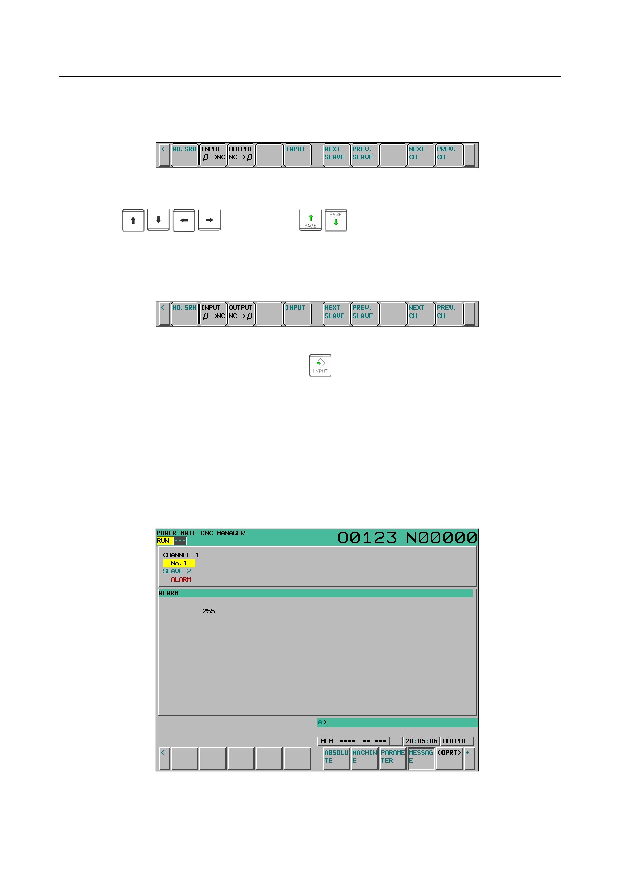
Parameter screen
The parameters required for the functions of the slave must be specified in advance.
Press soft key [PARAMETER] to display the parameter screen.
This screen displays only the bit and decimal data. For details of the parameters, refer to FANUC
SERVO MOTOR βi series I/O Link Option Maintenance Manual.
- 55 -
1.DISPLAY AND OPERATION
B-64305EN/03
• Selecting and searching for a parameter
1
Select the active slave.
2
Press the [(OPRT)] soft key. The following soft keys appear:
3
Enter a parameter number and press the [NO. SRH] soft key. The search starts.
You can also select a desired parameter number by pressing the cursor keys
and page keys
and moving the cursor.
• Setting a parameter
You can directly set an parameter of the I/O Link βi slave from the CNC.
1
Select a desired parameter using either of the above methods.
2
Press the [(OPRT)] soft key. The following soft keys appear:
3
Enter setting data.
4
Press the [INPUT] soft key or MDI key
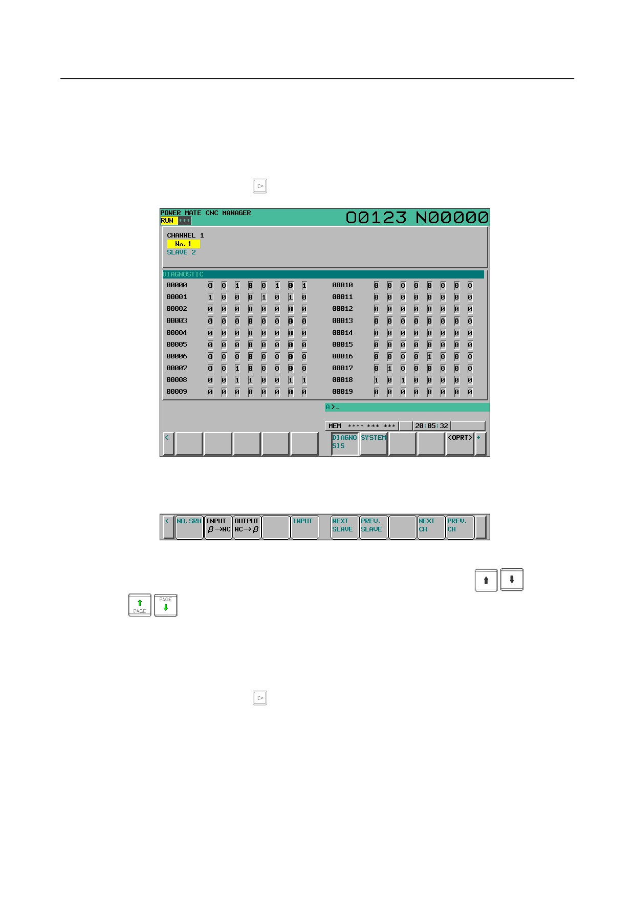
Alarm screen
If an alarm is issued for the slave, “ALARM” is displayed in the slave status field in the upper section of
the screen.
At this time, you can display the alarm screen to check the details of the alarm.
Up to 40 alarm codes are displayed on the screen.
For details of the alarms, refer to FANUC SERVO MOTOR βi series I/O Link Option Maintenance
Manual.
-
Display method
Press the [MESSAGE] soft key. On the screen, only error codes are displayed.
Example of displaying alarms for I/O Link βi of slave 2
- 56 -
B-64305EN/03
1.DISPLAY AND OPERATION
Diagnosis screen
The diagnosis screen displays diagnosis information of the slave.
Diagnosis data is displayed in bit or integer (decimal) representation. For details of diagnosis data, refer
to FANUC SERVO MOTOR βi series I/O Link Option Maintenance Manual.
-
Display method
1
Press the continuous menu key
2
Press soft key [DIAGNOSIS] to display the diagnosis screen.
Searching for diagnosis data
1
Select the active slave.
2
Press the [(OPRT)] soft key. The following soft keys appear:
3
Enter a diagnosis number and press the [NO. SRH] soft key. The search starts.
You can also select a desired parameter number by pressing the cursor keys
and page
keys
and moving the cursor.
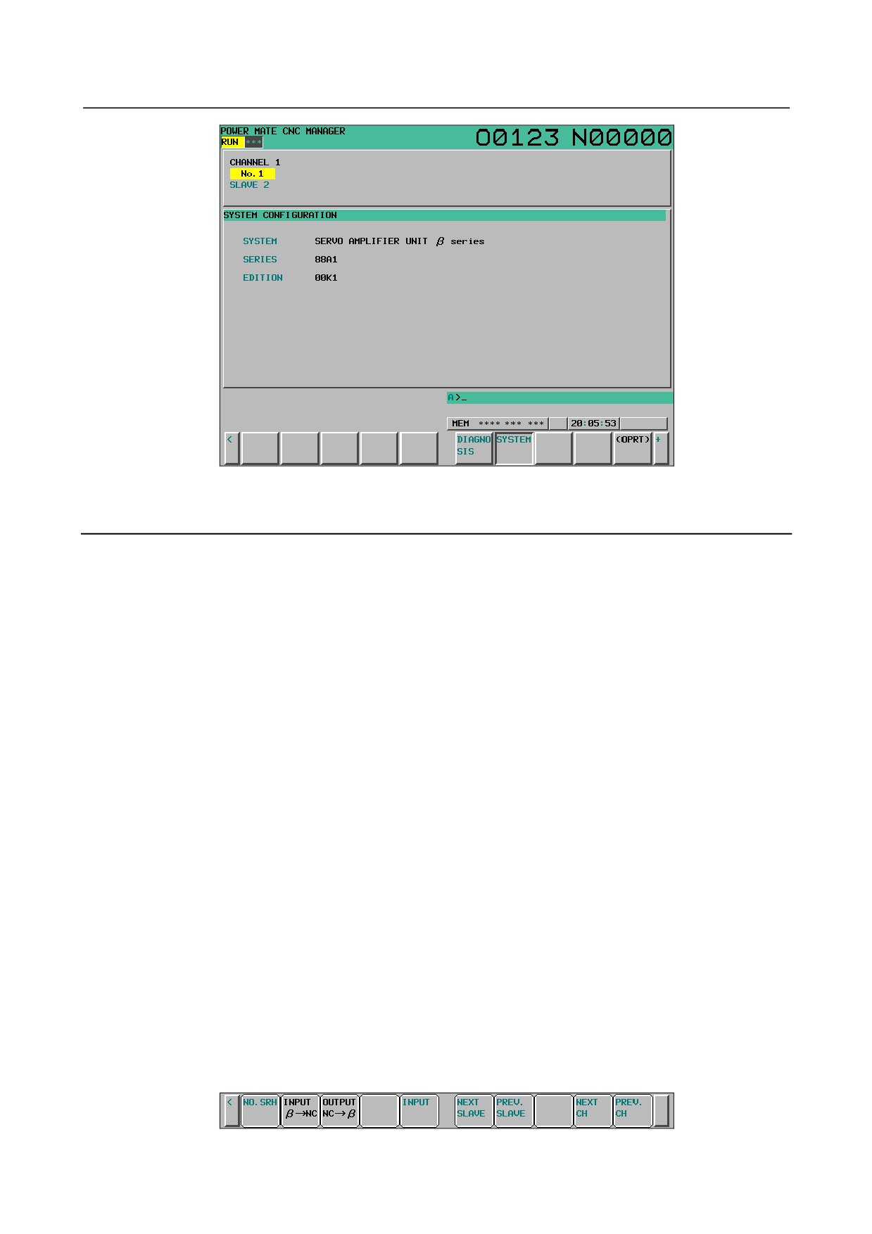
System configuration screen
The system configuration screen displays information on the system software of slaves.
-
Display method
1
Press the continuous menu key
2
Press the [SYSTEM] soft key to select the system configuration screen.
- 57 -
1.DISPLAY AND OPERATION
B-64305EN/03
Series and edition of the I/O Link βi system software
1.8.2
Inputting and Outputting Parameters
Outputting parameters
Parameters are output to the CNC memory or a memory card as a data file in the program format. Set
the first registration program number in parameter No.
8760. For each slave, program with a
predetermined number is created.
When parameters are output to the CNC memory, a program with the specified program number is
created.
When parameters are output to a memory card, a file is created, of which file name consists of the
specified program number and an extension PMM.
Program number = setting-of-parameter (parameter No. 8760) + (m - 1) × 100 + n × 10
m: Channel number (1 to 4)
n: Group number
Example:
When parameter No. 8760 is set to 8000
Channel 1 (I/O Link β: Group 0): 8000 + 0*100 + 0*10 = 8000
Channel 2 (I/O Link β: Group 1): 8000 + 1*100 + 1*10 = 8110
The group number is the slave number displayed in the slave status field in the upper section of the screen
in reverse video.
When bit 3 (PMO) of parameter No. 0961 is set to 1, the numbers of the parameters to be output can be
set only with a group number.
(No channel number is used.)
Either the CNC memory or the memory card is selected as an input/output destination device according to
the settings of bits 1 (MD1) and 2 (MD2) of parameter No. 0960.
Connect a memory card or check the unused area of the CNC memory, then follow the steps below:
1
For 2-path control in T series systems, the Power Mate CNC manager screen is displayed directly
from a path 1 screen.
2
Select the active slave.
3
Press the [(OPRT)] soft key. The following soft keys appear:
- 58 -
B-64305EN/03
1.DISPLAY AND OPERATION
4
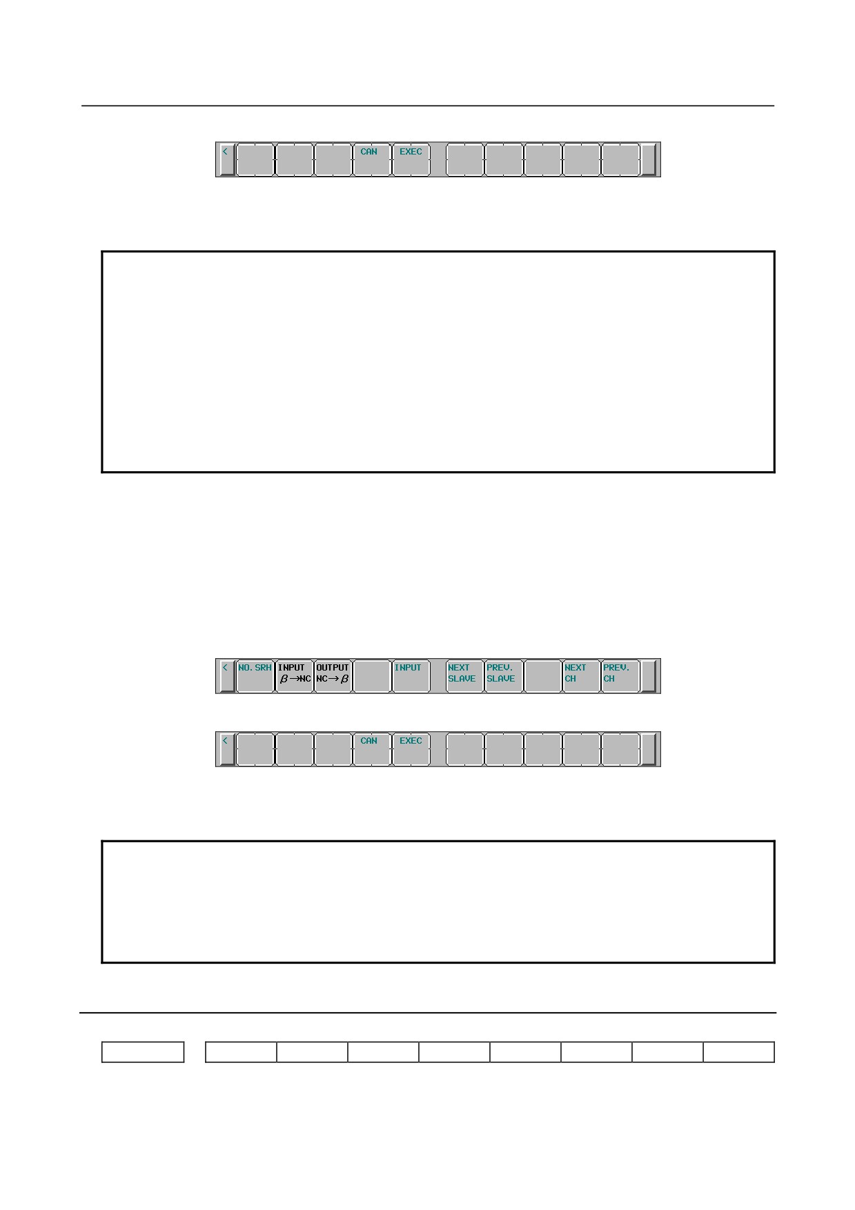
Press the [INPUT β→NC] soft key. The following soft keys appear:
5
Press the [EXEC] soft key.
During input, “INPUT” blinks in the message field.
NOTE
1 Parameters can be saved in other than the MEM mode or in the emergency stop
status.
2 To output parameters in a memory card, if a file with the same name is found in
the memory card, the parameters cannot be output. Delete the file from the
memory card or change the file name by setting parameter No. 8760.
To save parameters in a program area, save operation is performed according to
the setting of bit 2 (REP) of parameter No. 3201.
3 For 2-path control in T series systems, only the Power Mate CNC manager
screen of path 1 can be used to input and output parameters, and input/output is
enabled only for the CNC memory of path 1.
Inputting parameters
A data file of parameters output to the CNC memory or a memory card as a program is input to the slave
determined by the program number. The program number and device are determined as described in
“Outputting parameters.”
1
For 2-path control in T series systems, the Power Mate CNC manager screen is displayed directly
from a path 1 screen.
2
Select the active slave.
3
Press the [(OPRT)] soft key. The following soft keys appear:
4
Press the [OUTPUT β→NC] soft key. The following soft keys appear:
5
Press the [EXEC] soft key.
During output, “OUTPUT” blinks in the message field.
NOTE
1 Parameters can be input in other than the MEM mode or in the emergency stop
status.
2 For 2-path control in T series systems, only the Power Mate CNC manager
screen of path 1 can be used to input and output parameters, and input/output is
enabled only for the CNC memory of path 1.
1.8.3
Parameters
#7
#6
#5
#4
#3
#2
#1
#0
0960
PPE
PMN
MD2
MD1
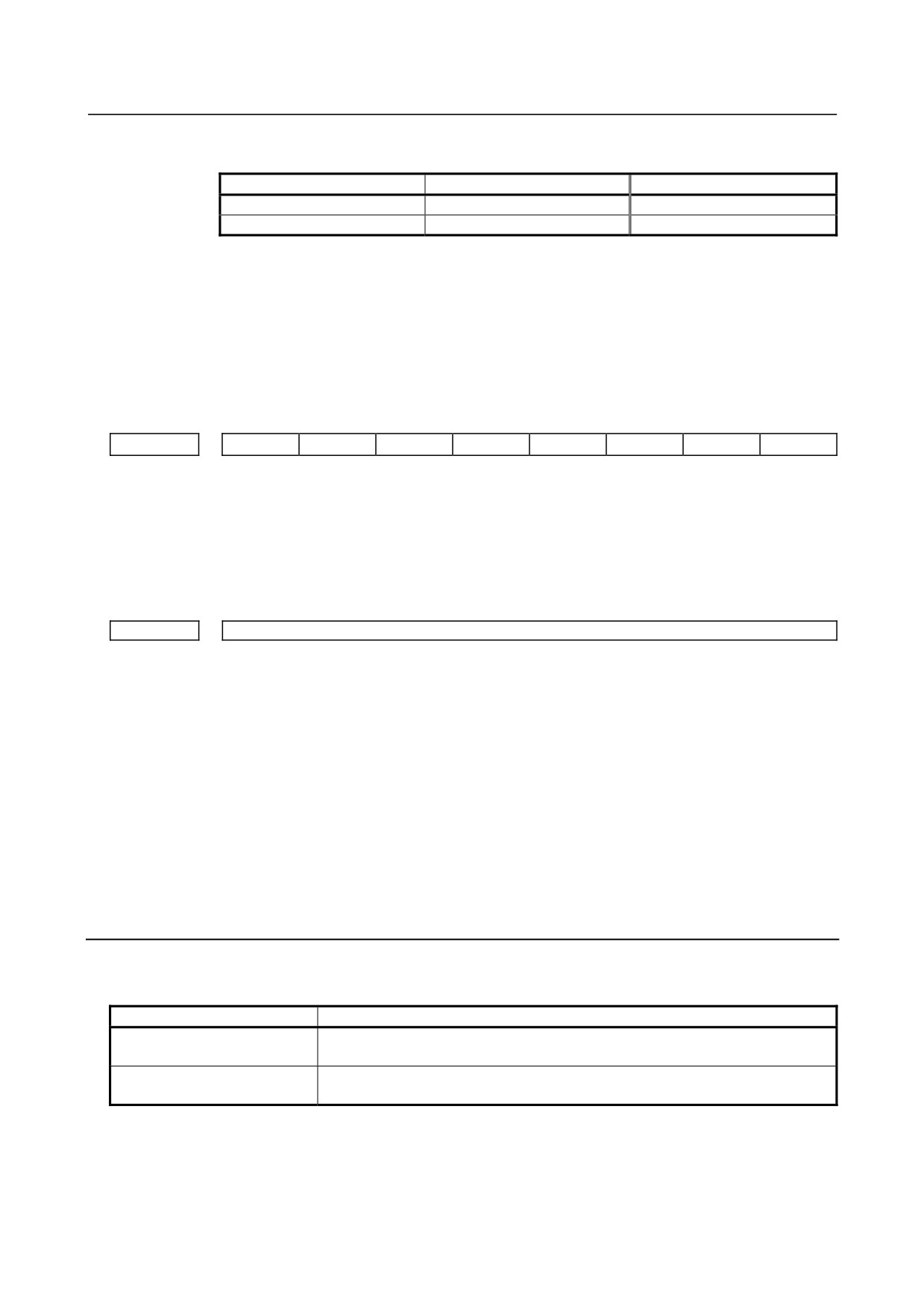
[Input type] Setting input
[Data type] Bit path
- 59 -
1.DISPLAY AND OPERATION
B-64305EN/03
#1 MD1
#2 MD2 The slave parameters are input from and output to either of the following devices:
Parameter MD2
Parameter MD1
I/O destination
0
0
Program memory
0
1
Memory card
#3 PMN The Power Mate CNC manager function is:
0: Enabled.
1: Disabled. (Communication with the slave is not performed.)
#4 PPE Setting slave parameters using the Power Mate CNC manager:
0: Can always be performed regardless of the setting of PWE.
1: Follows the setting of PWE.
#7
#6
#5
#4
#3
#2
#1
#0
0961
PMO
[Input type] Parameter input
[Data type] Bit
#3 PMO The O number of a program for saving and restoring the I/O Link β parameter is set based
on:
0: Group number and channel number
1: Group number only
8760
Program number of data input/output (Power Mate CNC manager)
[Input type] Setting input
[Data type] 2-word path
[Valid data range] 0 to 9999
This parameter sets the program numbers of programs to be used for inputting and
outputting slave data (parameters) when the Power Mate CNC manager function is used.
For a slave specified with I/O Link channel m and group n, the following program
number is used:
Setting + (m - 1) × 100 + n × 10
If the setting is 0, the parameters of the slave specified with channel 1 and group 0 cannot
be input from or output to the CNC memory because the program number is set to 0.
The parameters can be input from and output to a memory card.
(Set a value with which any used program number does not exceed 9999.)
Warning
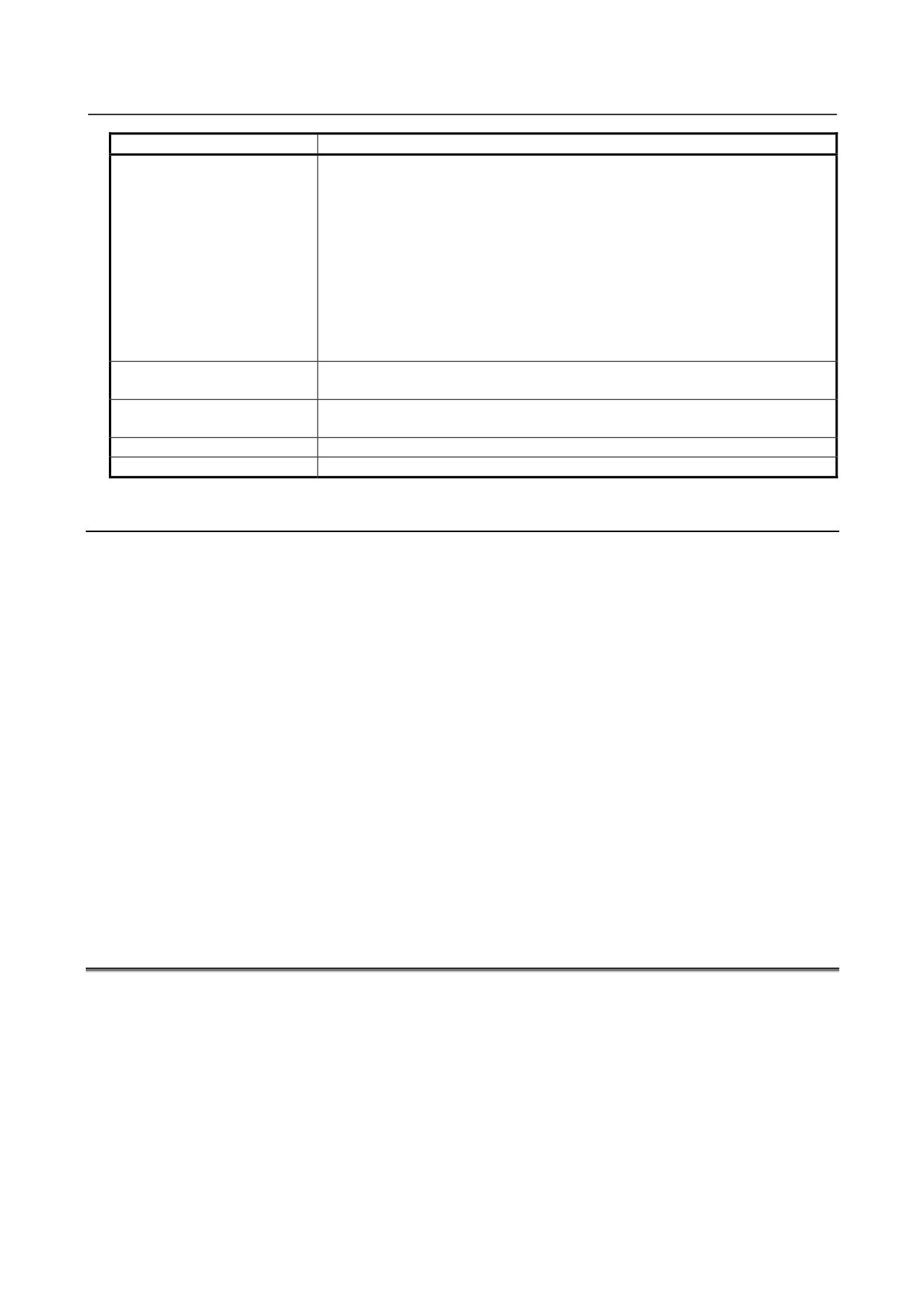
If an alarm is issued for the Power Mate CNC manager, a warning message is displayed.
Message
Description
DATA ERROR
An attempt was made to execute [PUNCH] (NC → β) for a program not found in
the program area.
WRITE PROTECTED
An attempt was made to execute [READ] (β → NC) for a program area when the
memory protection signal (KEY) is off.
- 60 -
B-64305EN/03
1.DISPLAY AND OPERATION
Message
Description
EDIT REJECTED
An attempt was made to execute [READ] (β → NC) when the program area
already contained a program with the same name as that to be created by
executing [READ] (β → NC).
An attempt was made to execute [READ] (β → NC) when the number of the
program to be created by executing [READ] (β → NC) was selected.
An attempt was made to execute [READ] (β → NC) when bit 0 (TVC) of CNC
parameter No. 0000 was set to 1.
(Parameters Nos. 0000 to 0019 are output,
but parameter No. 0020 and subsequent parameters are not output.)
An attempt was made to execute [PUNCH] (NC → β) when a memory card did
not contain any program for which [PUNCH] (NC → β) could be executed.
An attempt was made to execute [READ] (β → NC) for a protected memory card.
NO MORE SPACE
An attempt was made to execute [READ] (β → NC) when the program area did
not have enough unused space.
FORMAT ERROR
Data other than digits, signs, CAN, and INPUT was entered as the setting of a
parameter.
TOO MANY FIGURES
Data consisting of 9 or more digits was entered for a bit-type parameter.
DATA IS OUT OF RANGE
The setting exceeds the valid data range.
1.8.4
Notes
-
Connecting an I/O Link
When I/O Link βi is used as a slave of an I/O Link, the CNC assigns I/O addresses. The slave data is
input and output in 16-byte units. Therefore, be sure to specify 128 as the number of input/output
points.
Up to eight slaves can be connected.
The module name is OC02I (16-bit input) or OC02O (16-byte output).
BASE is always 0 and SLOT is always 1.
-
Function of ignoring the Power Mate CNC manager
After setting and checking data required for each slave connected, you can stop communication with the
Power Mate CNC manager function to send a command from the CNC ladder to the slave.
When bit 3 (PMN) of parameter No. 0960 is set to 1, communication between the CNC and the slave via
the I/O Link is all open to the ladder. While this bit is 1, the Power Mate CNC manager function does
not operate.
-
Data protection key
When the program data protection key of the CNC is on, no parameters can be input to the CNC program
memory.
1.9
MAINTENANCE INFORMATION SCREEN
The maintenance information screen is provided to record the history of maintenance performed by a
service person of FANUC or machine tool builder.
The screen has the following features:
• MDI alphabetical input is allowed.
(Only in Japanese display, even the single-byte kana input mode is allowed.)
• The recording screen can be scrolled in units of lines.
• Edited maintenance information can be input and output.
• Records are stored in Flash ROM.
• Double-byte (Shift JIS) code can be displayed.
- 61 -
1.DISPLAY AND OPERATION
B-64305EN/03
1.9.1
Displaying the Maintenance Information Screen
1.
Press function key
2.
Press continuous menu key
several times until soft key [M-INFO] is displayed.
3.
Press the soft key [M-INFO]. The maintenance information screen appears.
When selected, the maintenance information screen shows the latest information.
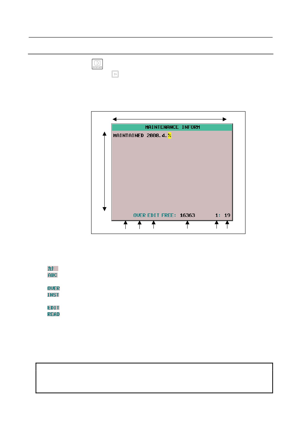
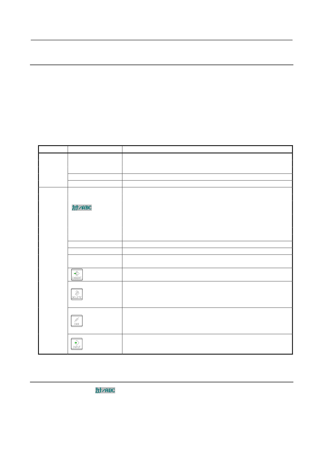
The status (mode, number of empty character spaces, current cursor line, current column number) is
displayed at the bottom of the screen.
Column
Line
<1>
<2>
<3>
<4>
<5> <6>
Fig. 1.9.1 (a) MAINTENANCE INFORMATION screen
Status display
<1> Kana/alphabetic
(Blank): English input mode (Only In the display which is not Japanese)
: Single-byte kana input mode (Only in Japanese display)
: English input mode (Only in Japanese display)
<2> OVER / INSERT
: Overwrite mode
: Insert input mode.
<3> EDIT / READ
: Edit mode / Editing allowed
: View mode / Editing inhibited
<4> Number of empty character spaces
Number of empty character spaces as single-byte characters
<5> Current cursor line
Current cursor position on the line
<6> Current cursor column
Current cursor position on the column
NOTE
The numbers of lines and columns that can be displayed by each LCD are:
•
10.4” display unit: 37 characters × 12 lines
•
8.4” display unit: 38 characters × 11 lines
- 62 -
B-64305EN/03
1.DISPLAY AND OPERATION
1.9.2
Operating the Maintenance Information Screen
The maintenance information screen has view mode and edit mode, which are selected by pressing the
soft key [END] or [EDIT].
Initially, view mode is selected. To start editing, select edit mode by pressing the soft keys [(OPRT)] and
[EDIT]. When the editing is completed, press the soft key [END] key. Then, select soft key [SAVE] or
[QUIT]. If [SAVE] is selected, edited data is saved to FLASH-ROM. If [QUIT] is selected, no edited
data is saved to FLASH-ROM.
To scroll the screen showing the recorded information, press a cursor keys or page keys on the MDI
panel.
The following keys are used for editing (character input) and viewing:
Table 1.9.2 (a) Table of (edit) operations on the maintenance information screen
Mode
Key
Description
View
Soft key
[EDIT]
Allows editing.
[JUMP]
Displays the beginning or the end.
Cursor keys
Scrolls the screen up or down.
Page keys
Scrolls the screen up or down in units of whole screens.
Edit
Soft key
[END]
Ends editing. Select whether to save the edited data.
Switches between single-byte kana input and alphabetic input modes.
[
]
(Japanese display only.)
[CLEAR]
Clears all maintenance information. (This key is enabled when the
parameter MDC (No.3116#7) is set to 1.)
[I/O]
Performs [F INPUT] or [F OUTPUT] operation for maintenance information.
[JUMP]
Moves the cursor to the beginning or end.
Cursor keys
Moves the cursor position up or down.
Page keys
Scrolls the screen up or down in units of whole screens.
Address / numeric
Allows alphabetical or numeric input.
(See the next subsection for
keys
explanations about single-byte kana input.)
key
Switches between insert and overwrite modes.
• If the key input buffer does not contain any character, deletes the one
character at the cursor position.
key
• If the key input buffer contains characters, deletes the characters from the
buffer.
• If the key input buffer does not contain any character, deletes the one
character before the cursor.
key
• If the key input buffer contains characters, deletes the one character from
the buffer.
• If the key input buffer does not contain any character, starts a new line.
key
• If the key input buffer contains characters, outputs the characters from the
buffer to the information screen.
1.9.3
Single-Byte Kana Input on the Maintenance Information
Screen
By pressing soft key [
], you can switch between single-byte kana input and alphabetic input
modes.
In single-byte kana input mode, alphabetic characters are converted in accordance with the "single-byte
kana/Roman character conversion table" and resultant single-byte kana characters are displayed in the key
input buffer. (Japanese display only.)
- 63 -
1.DISPLAY AND OPERATION
B-64305EN/03
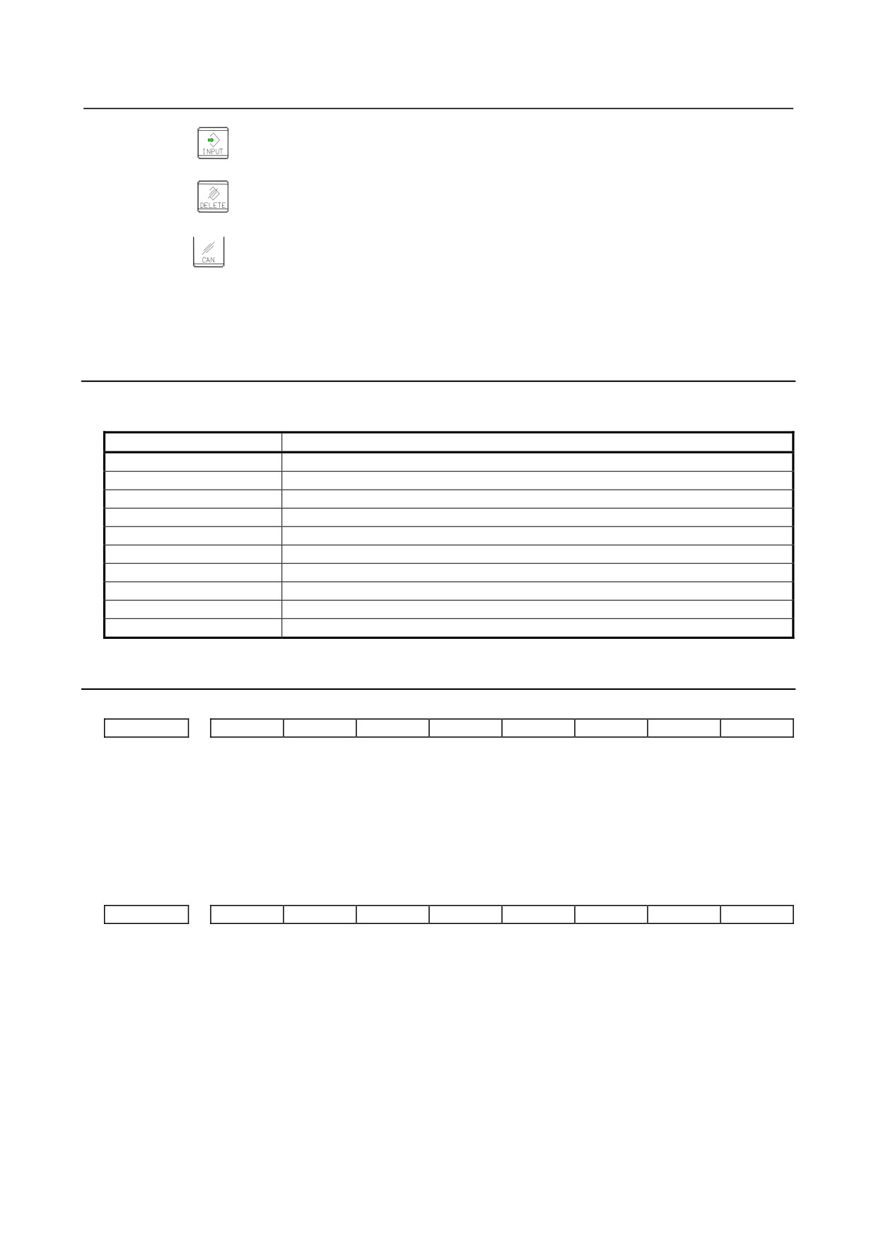
Pressing the
key causes the characters in the key input buffer to be output to maintenance
information.
Pressing the
key causes the characters to be deleted from the key input buffer and the one
character of the maintenance information on which the cursor is positioned to be deleted.
Pressing the
key causes cancels conversion, and deletes one character from the key input buffer. If
the key input buffer does not contain any character, the one character of the maintenance information that
immediately precedes the cursor is deleted.
1.9.4
Warnings that Occurs on the Maintenance Information
Screen
The following warnings occur on the maintenance information screen.
Warning message
Meaning
NO MORE SPACE
An overflow occurred in CNC memory.
ALARM
The operation could not be performed because an alarm was generated in the CNC.
BUSY
Wait for CNC processing to end or make a retry.
ILLEGAL DATA
Investigate data and correct it as required.
WRONG MODE
The CNC is in wrong mode.
COMMAND ILLEGAL USE
A corresponding CNC option cannot be found.
PARAMETER ERROR
CNC parameter settings contain an error.
EDIT REJECTED
An attempt was made to perform an edit operation on data that could not be edited.
WRITE PROTECT
Writing is prohibited.
COMMAND REJECT
The CNC rejected the execution of the processing. Check the execution conditions.
1.9.5
Parameter
#7
#6
#5
#4
#3
#2
#1
#0
3116
MDC
[Input type] Setting input
[Data type] Bit path
#7 MDC Maintenance information data:
0: Cannot be erased entirely.
1: Can be erased entirely.
#7
#6
#5
#4
#3
#2
#1
#0
3206
MIF
[Input type] Parameter input
[Data type] Bit
#1 MIF Editing of the maintenance information screen is:
0: Not prohibited.
1: Prohibited.
- 64 -
B-64305EN/03
1.DISPLAY AND OPERATION
#7
#6
#5
#4
#3
#2
#1
#0
8901
MEN
[Input type] Setting input
[Data type] Bit path
#7 MEN The periodic maintenance screen is:
0: Displayed.
1: Not displayed.
1.10 CONTENTS-OF-MEMORY DISPLAY SCREEN
The contents-of-memory display screen can be used to display the contents of the CNC memory, starting
at a specified address.
1.10.1 Display Method
1
Set bit 0 (MEM) of parameter No. 8950 to 1 to display the contents-of-memory display screen.
2
Press the function key
3
Press the continuous menu key
and then the soft key [MEMORY] belonging to the chapter
selection soft key.
The screen shown below appears.
Fig. 1.10.1 (a) Contents-of-memory display screen (10.4-inch)
4
Key in the address (hexadecimal) of a desired location and press the soft key [ADDRES SEARCH].
256 bytes of data are displayed, starting at the specified address.
(Example:
100000 + soft key [ADDRES SEARCH] will start displaying at 100000H.)
5
Displayed data can be switched using the page keys
and the cursor keys
6
To select the type of data to be displayed, use the soft keys [BYTE], [WORD], [LONG], and
[DOUBLE].
- 65 -
1.DISPLAY AND OPERATION
B-64305EN/03
1.10.2 Display Formats on Contents-of-Memory Display Screen
The format of memory content displays can be selected from the following four:
Byte display (1-byte hexadecimal display)
Word display (2-byte hexadecimal display)
Long display (4-byte hexadecimal display)
Double display (8-byte decimal display—double precision floating point display)
Up to 256 bytes of memory contents can be displayed on the screen.
NOTE
1 When specifying an address, do not suffix it with "H" to indicate a hexadecimal.
Otherwise, an alarm is issued to notify of an illegal format.
2 If the word display format is selected, each input address is rounded to 2 bytes.
If the long or double display is selected, each input address is rounded to 4
bytes.
WARNING
1 Trying to specify the address of any memory location to which access is inhibited
for the address search function will result in a system alarm.
Before starting to use the address search function, confirm that the address you
will specify is accessible, and be sure to input the address correctly.
2 This function is intended for maintenance purposes. It should not be used by
general users.
- 66 -
B-64305EN/03
2.LCD-MOUNTED TYPE CNC HARDWARE
2 LCD-MOUNTED TYPE CNC HARDWARE
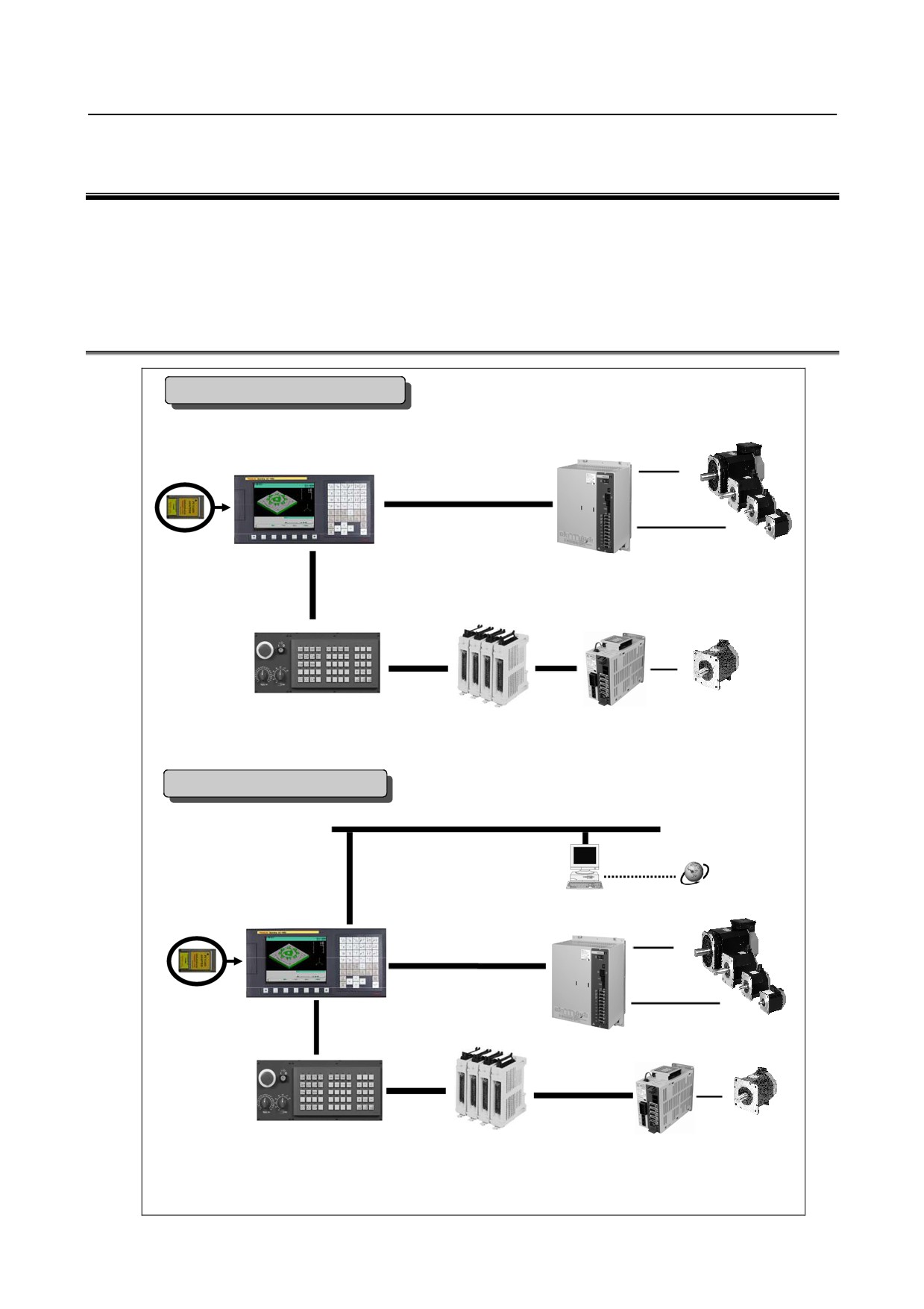
The FANUC Series 0i-D/0i Mate-D of the LCD-mounted type is a CNC consisting of a liquid crystal
display on the back of which the CNC control unit is mounted to incorporate it. This chapter describes the
functions of LCD-mounted type CNC control unit printed circuit boards and axis cards on the printed
circuit boards as well as how to replace consumables.
2.1
HARDWARE CONFIGURATION
Series 0i Mate-D system configuration
βi spindle motors
8.4” LCD/MDI (color)
βi SVSP
FSSB
βiS servo motors
FANUC I/O Link
Distributed I/O
I/O Link βi servo amplifier
Machine operator’s panel
βiS servo motor
I/O on the machine side
All units that can be connected with the I/O Link are usable.
The number of usable I/O points is limited, though.
Series 0i-D system configuration
Ethernet 100 base TX (*)
Internet
8.4” LCD/MDI (color)
PC
10.4” LCD (color) + MDI
βi spindle motors
βi SVSP
FSSB
FANUC I/O Link
βiS servo motors
Distributed I/O
The αi series is also usable.
Machine operator’s panel
βiS servo motors
I/O on the machine side
I/O Link βi servo amplifier
All units that can be connected with the I/O Link are usable.
(*) To connect to the 10BASE-T Ethernet port, use a HUB that meets the following conditions:
100BASE-TX capability, auto-negotiation, and store & forward method
- 67 -
2.LCD-MOUNTED TYPE CNC HARDWARE
B-64305EN/03
2.2
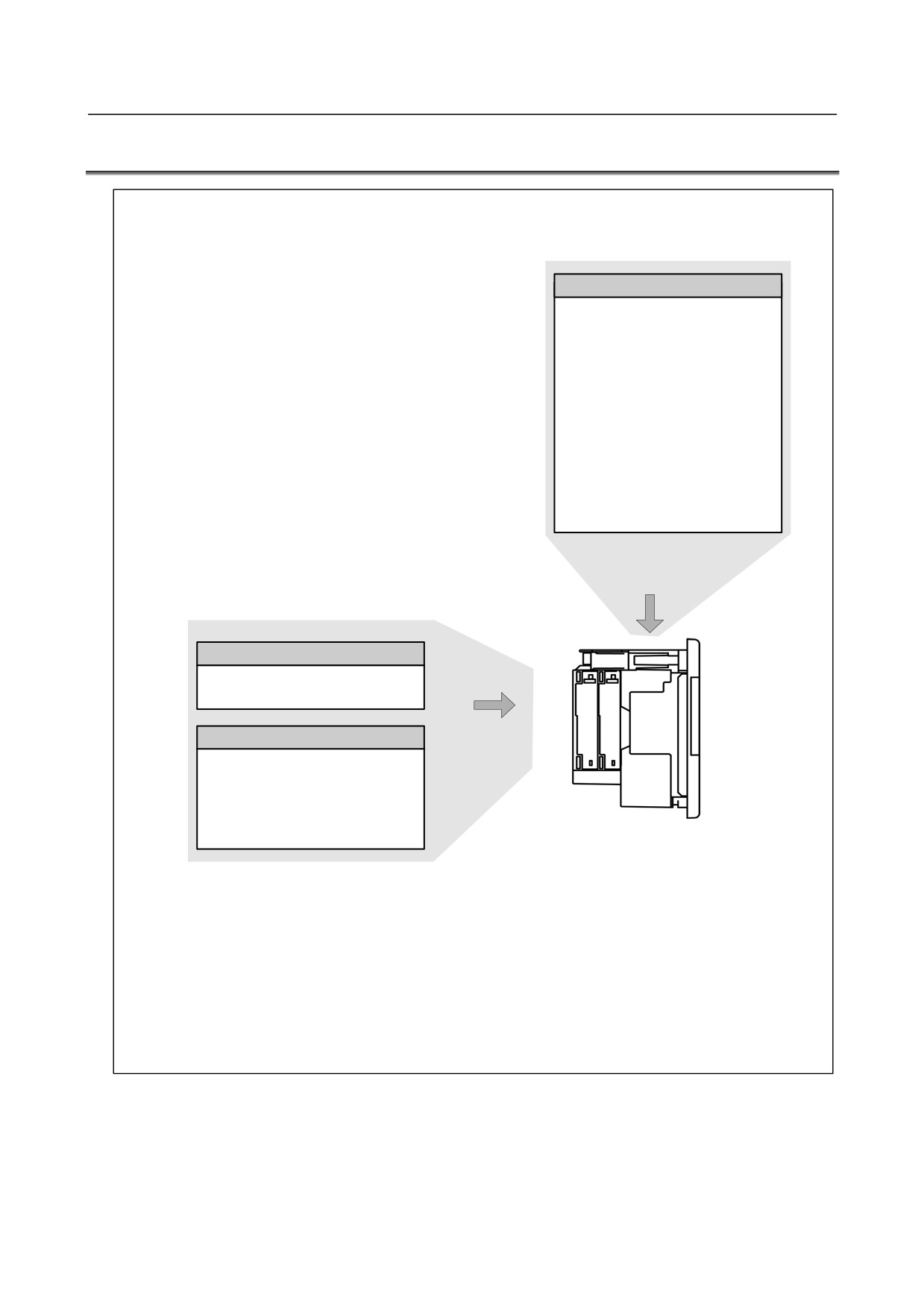
HARDWARE OVERVIEW
Main board
• CPU for controlling CNC
• Power supply
• Axis control
• Spindle interface
• LCD/MDI interface
• I/O Link
• PMC control function
• High-speed DI
• RS-232C
• Memory card interface
• Ethernet (Series 0i only)
Basic system
Fast Ethernet board
Data server function
Ethernet communication function
Various types of network boards
Options
PROFIBUS-DP
master
boardPROFIBUS-DP
slave
board
FL-net board
Device Net master board
Unit without optional slots
Device Net slave board
or
Unit having two optional slots
The control unit of the Series 0i Mate has no optional slots, so no option board can be inserted.
A unit with optional slots can have as many option boards as option slots.
The Fast Ethernet board can be inserted into only the slot on the LCD side.
- 68 -
B-64305EN/03
2.LCD-MOUNTED TYPE CNC HARDWARE
2.3
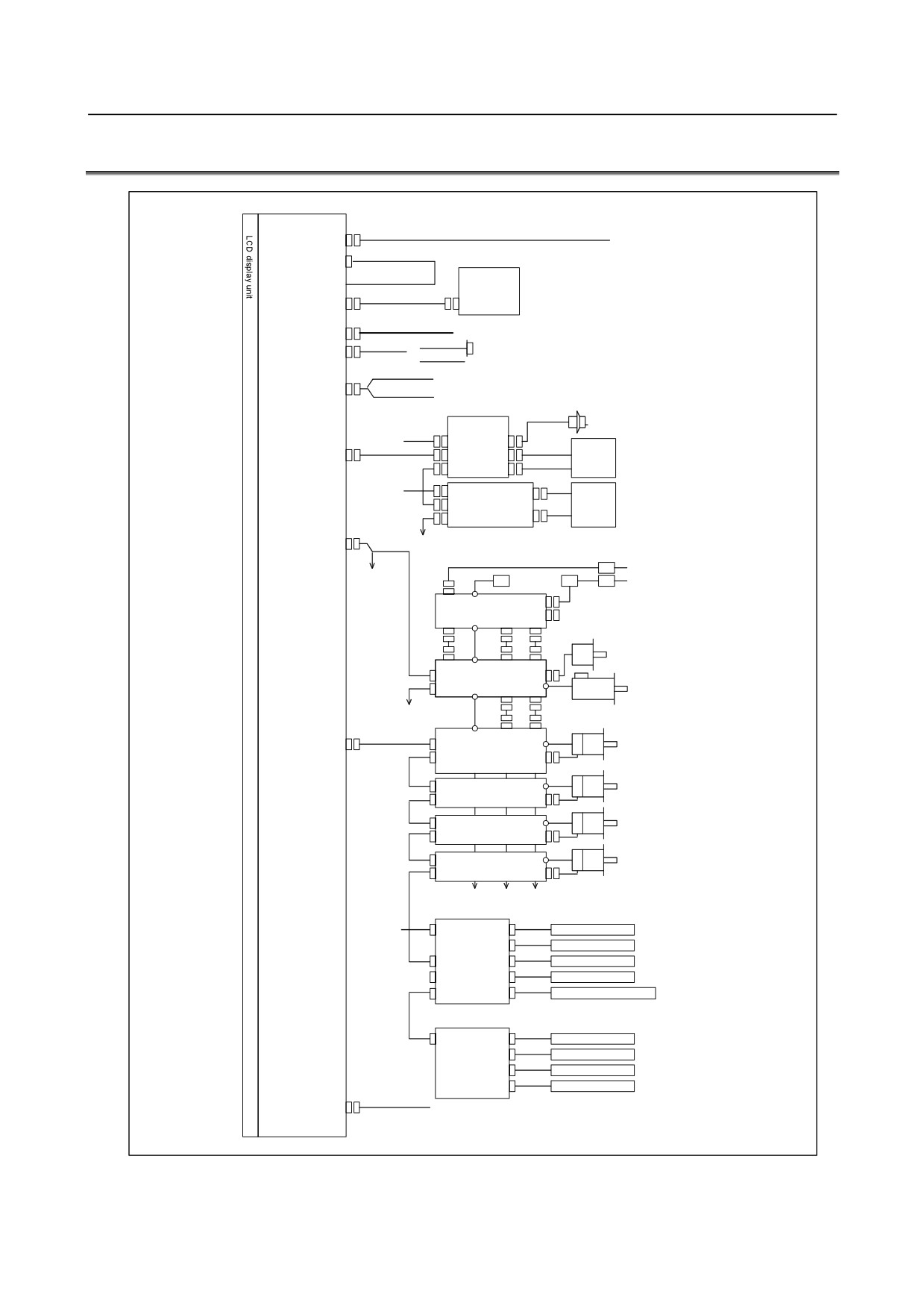
TOTAL CONNECTION DIAGRAMS
Main board
24V-IN(CP1)
24 VDC power supply
(CA122)
Soft key cable
MDI UNIT
MDI(JA2)
CK1
R232-1(JD36A)
RS-232-C I/O device
R232-2(JD36B)
{
RS-232-C I/O device
Touch panel
Analog output for tool drives
A-OUT&HDI(JA40)
High-peed skip input
Distributed I/O
Manual pulse generator
board
24VDC
CPD1
JA3
I/O Link(JD51A)
JD1B
Operator's
JD1A
panel
24VDC
CPD1
Distributed
Power
JD1B
I/O board,
magnetics
I/O unit, etc.
JD1A
cabinet
SPDL(JA41)
Circuit breaker
200VAC
AC reactor
To 3rd spindle
200VAC
MCC
Circuit breaker
αi PS
Position coder
αi SP
To 2nd spindle
Serial spindle motor
FSSB(COP10A)
COP10B
αi SV
Servo motor
COP10A
COP10B
αi SV
Servo motor
COP10A
COP10B
αi SV
Servo motor
COP10A
COP10B
αi SV
Servo motor
COP10A
(In this figure, a 1-axis amplifier is used.)
Separate detector interface unit 1
24VDC
CP11A
JF101
Linear scale, axis 1
JF102
Linear scale, axis 2
COP10B
JF103
Linear scale, axis 3
COP10AJF104
Linear scale, axis 4
CNF1
JA4A
Absolute scale battery
(Required only when an absolute scale is used)
Separate detector interface unit 2
CP11AJF101
Linear scale, axis 1
JF102
Linear scale, axis 2
JF103
Linear scale, axis 3
JF104
Linear scale, axis 4
ETHERNET(CD38A)
Ethernet
- 69 -
2.LCD-MOUNTED TYPE CNC HARDWARE
B-64305EN/03
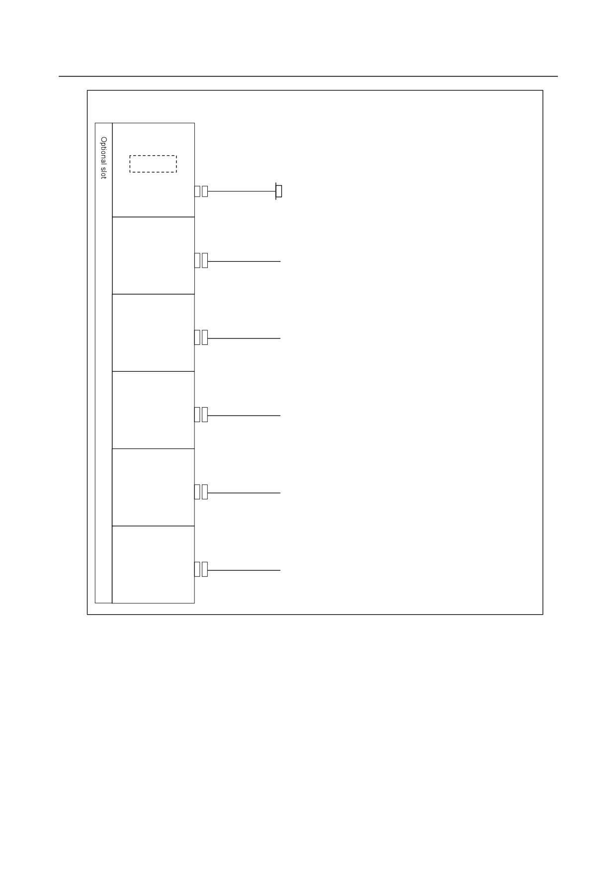
When optional functions are provided
Fast Ethernet board
Memory card
Prepare the memory card recommended by FANUC.
ETHERNET(CD38R)
Ethernet
PROFIBUS-DP
master board
PROFI(CN1)
Another NC or Profibus
device
PROFIBUS-DP
slave board
PROFI(CN2)
Another NC or Profibus
device
DeviceNet
master board
DVNET(TBL)
Another NC or DeviceNet
device
DeviceNet
slave board
DVNET(TBL)
Another NC or DeviceNet
device
FL-net board
FLNET(CD38N)
FL-net device
- 70 -
B-64305EN/03
2.LCD-MOUNTED TYPE CNC HARDWARE
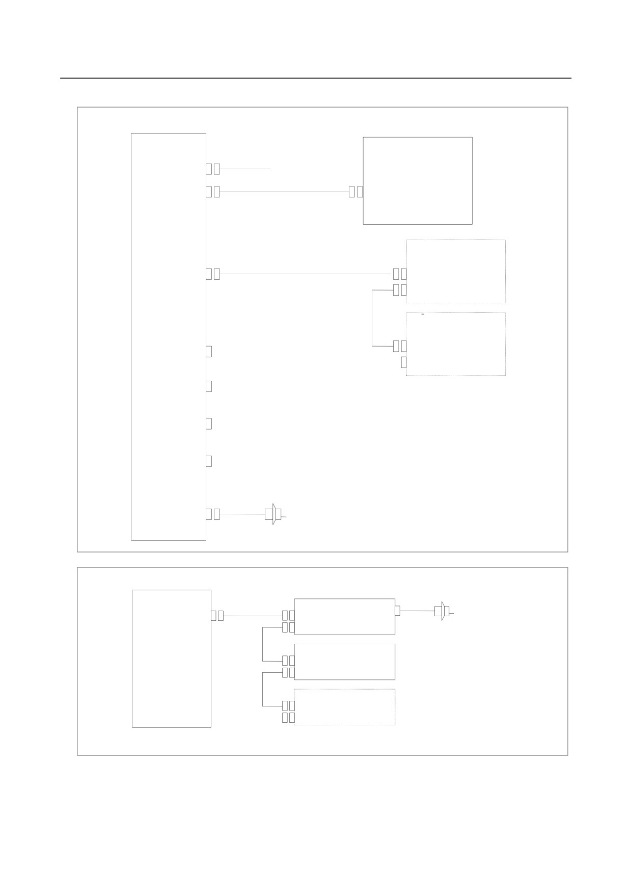
Example of I/O Link connection
Series 0i
I/O Unit for 0i
Series 0i
Main board
(CPD1)
24VDC
I/O Link (JD1B)
JD51A
I/O for operator’s
panel
I/O Link
I/O Link (JD1A)
JD1B
JD1A
DI : 96 points
DO : 64 points
I/O Link βi
servo amplifier
DI/DO-1
JD1B
(CB104)
JD1A
DI/DO-2
(CB105)
The order in which slave devices are
connected via I/O Link can be
DI/DO-3
determined freely.
(CB106)
DI/DO-4
(CB107)
MPG(JA3)
Manual pulse generator (up to three units)
Series 0i Mate
Series 0i Mate
I/O for operator’s panel(with MPG)
Main board
I/O Link
JA3
I/O Link (JD51A)
JD1B
Manual pulse generator
JD1A
(up to three units)
I/O for operator’s panel
(without MPG)
JD1B
JD1A
I/O Link βi servo
(For the 0i Mate, the number of connectable
amplifier
amplifiers depends on the model.)
The order in which slave devices are connected via
I/O Link can be determined freely.
- 71 -
2.LCD-MOUNTED TYPE CNC HARDWARE
B-64305EN/03
2.4
CONFIGURATION OF PRINTED CIRCUIT BOARD
CONNECTORS AND CARDS
2.4.1
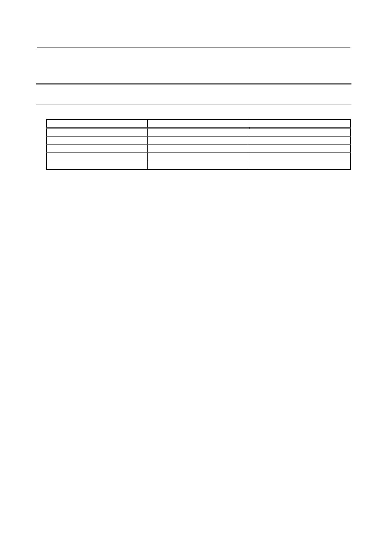
Main Board
-
Main board specification
Name
CNC model
Specification
Main board A0
0i
A20B-8200-0540
Main board A1
0i
A20B-8200-0541
Main board A2
0i
A20B-8200-0542
Main board A3
0i
A20B-8200-0543
Main board A5
0i Mate
A20B-8200-0545
- 72 -
B-64305EN/03
2.LCD-MOUNTED TYPE CNC HARDWARE
-
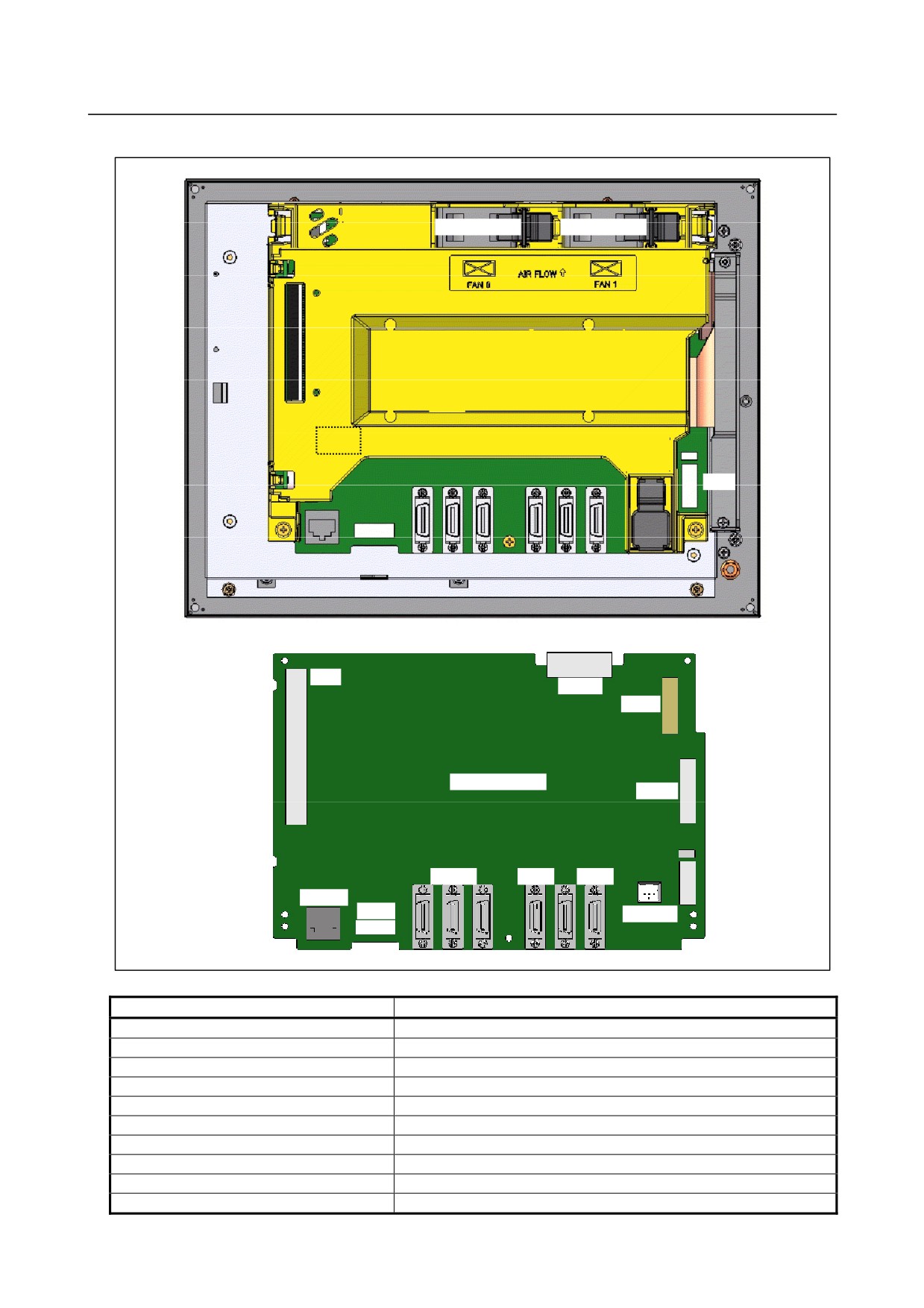
Connector mounting location
Fan motor
Fan motor
Rear of unit
COP10A
(COP10A is a connector installed on the axis card.)
Battery
CP1
JA2
JD36B JA40
JA41
CD38A CA122
JD36A
JD51A
JGA
CA121
CA79A
Main board
CA88A
JD36A
JA40
JA41
CP1
CD38A
CA122
CA114
JA2
JD36B
JD51A
Connector number
Application
COP10A
Servo amplifier (FSSB)
JA2
MDI
JD36A
RS-232-C serial port 1
JD36B
RS-232-C serial port 2 (Note)
JA40
Analog spindle / high-speed DI
JD51A
I/O Link
JA41
Serial spindle / position coder
CP1
DC24V-IN
JGA
Back panel interface
CA79A
Video signal interface
- 73 -