FANUC SERVO AMPLIFIER a series. DESCRIPTIONS (B-65162E/03) - page 10

B-65162E/03
9.CONNECTION
(11) Detailed description of the connection of cable K26
Dynamic brake module
Cable: Fire-retardant polyflex wire (maximum conductor temperature 105°C) or
equivalent to LMFC manufactured by The Furukawa Electric Co.,
Ltd., 5.5 mm2 or larger
Crimp terminal:
5.5-5
Crimp terminal:
5.5-6
273
9. CONNECTION
B-65162E/03
(12) Detailed description of the connection of cable K27
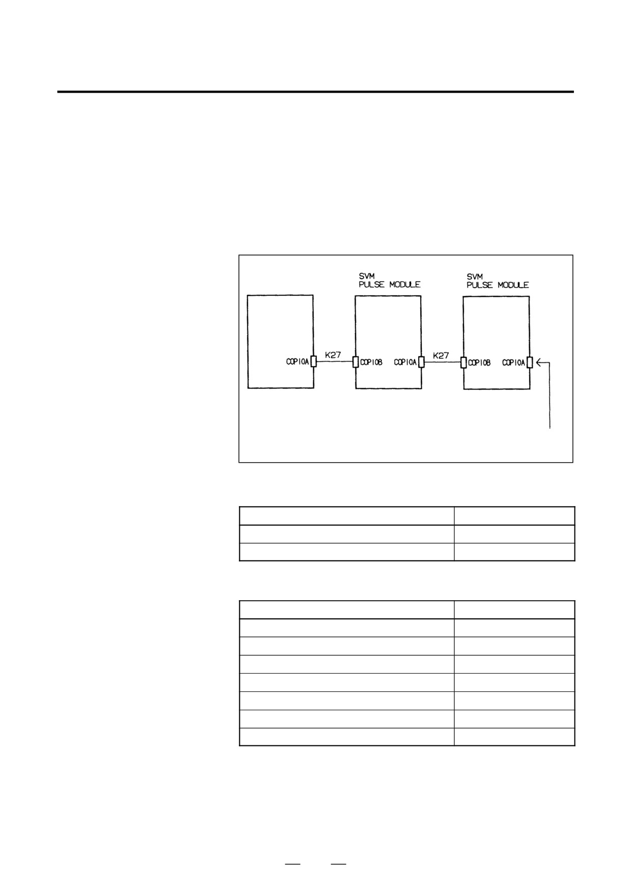
Cable K27 is an optical fiber cable used in the FSSB interface.
The cable is run from connector COP10A in the CNC, SVM, or pulse
module to connector COP10B in the SVM or pulse module.
Connector COP10A of a module at the end of the cable chain must be
covered with the cap supplied with the module.
Refer to the applicable CNC connection manual for detailed specifications
of the optical fiber cable.
CNC unit
Protective cap
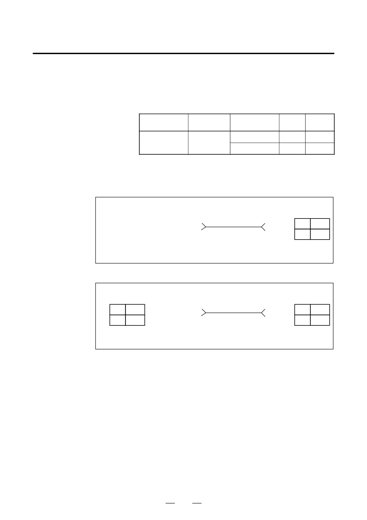
(1) Connection between two SVM units or between the SVM and pulse
module (optical cable extension)
Specification
Cable length
A66L-6001-0023#L150R0
15cm
A66L-6001-0023#L300R0
30cm
(2) Connection between the CNC and SVM or between the CNC and
pulse module (optical cable subscriber line)
Specification
Cable length
A66L-6001-0026#L1R003
1m
A66L-6001-0026#L5R003
5m
A66L-6001-0026#L7R003
7m
A66L-6001-0026#L10R003
10m
A66L-6001-0026#L20R003
20m
A66L-6001-0026#L30R003
30m
A66L-6001-0026#L50R003
50m
274
B-65162E/03
9.CONNECTION
(13) Detailed description of the connection of cable K28
Cable K28 is used to connect a battery to the ABS pulse coder.
One battery can be connected to multiple servo amplifier modules in
series, using the following connector with a lock.
Connector with lock
Manufacturer’s
Product
Drawing number
Manufacturer
Quantity
model code
name
Japan Aviation
IL-L2S-S3L-B(N)
Housing
1
A06B-6093-K303
Electronics
Industry, Ltd.
IL-C2-1-00001
Contact
2
A special crimping tool is necessary to attach contacts to a cable. It should
be ordered from the manufacturer (Japan Aviation Electronics Industry,
Ltd.) separately.
(1) Connection between the battery unit and SVM
Battery unit side
SVM side
Two 0.3 mm2 shielded wires
Connector
Terminal 1, white, crimp terminal 1.25-4
White 1
1
White
Terminal 2, black, crimp terminal 1.25-4
Black 2
2
Black
Housing IL-L2S-S3L-B(N)
Contact IL-C2-1-00001
(2) Connection between two SVM units
SVM side
SVM side
Connector
Two 0.3 mm2 shielded wires
Connector
1
White
Terminal 1, white
White 1
1
White
Terminal 2, black
Black 2
2
Black
2
Black
Housing IL-L2S-S3L-B(N)
Housing IL-L2S-S3L-B(N)
Contact IL-C2-1-00001
Contact IL-C2-1-00001
275
9. CONNECTION
B-65162E/03
9.2.3
Spindle Amplifier
Module Connection
Diagram
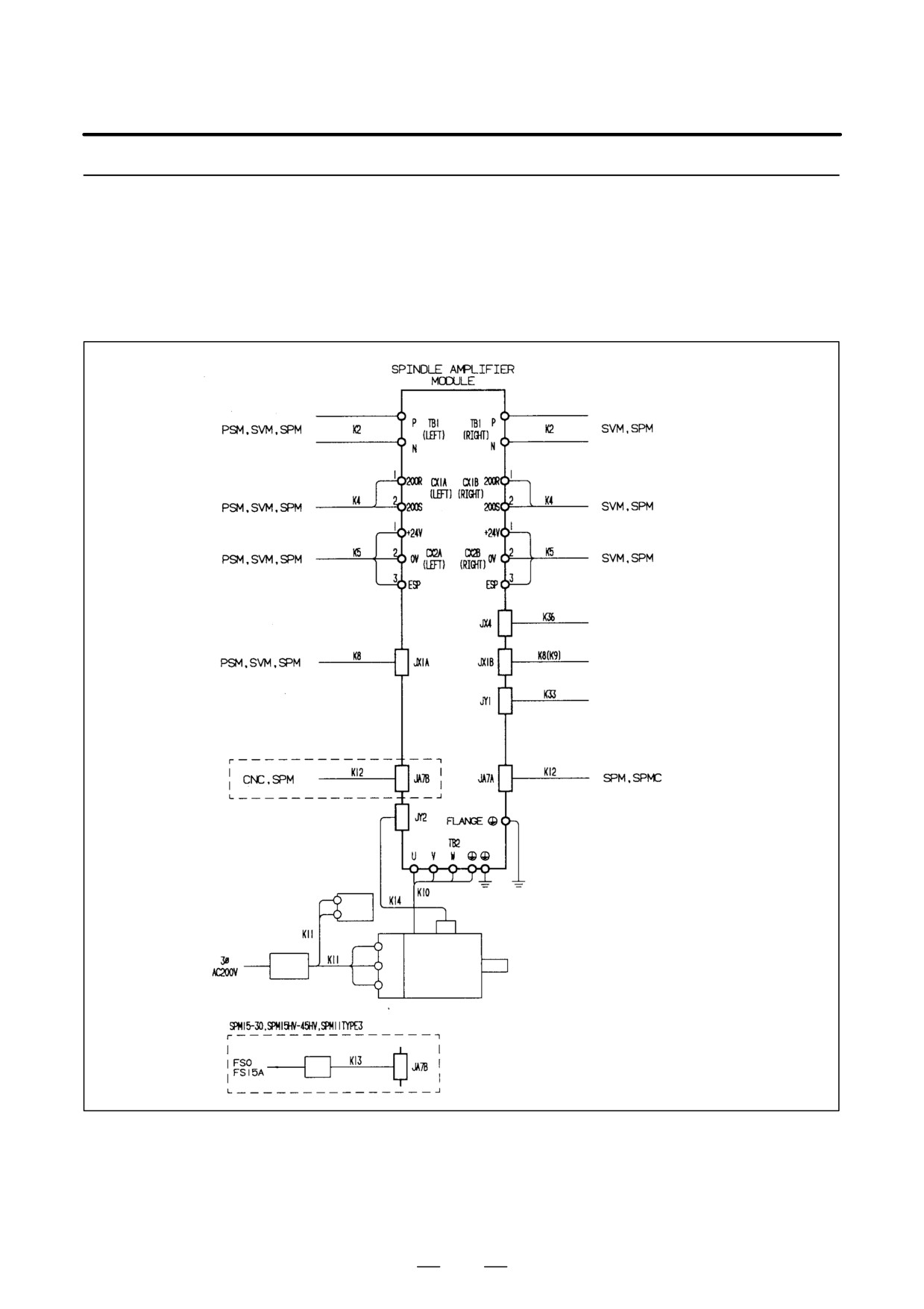
Spindle amplifier module (SPM)
(Note1)
To external equipment that
uses position coder signal
SVM, SPM
(terminating connector)
Load meter, speedometer,
analog override
(Note 2)
For SPM-45 and -75HV only
Cooling
fan
M sensor (pulse generator)
Spindle
motor
Circuit breaker 2
Fan motor
(Note 1)
(Note 2)
Optical IO link adapter
Opti
cal cable
The connector to be used varies according to the type of the detector being
used. The interfaces for individual detectors are explained separately
later.
See Section 5.2.3 for information about the cable used for the connection
to a frame ground.
276
B-65162E/03
9.CONNECTION
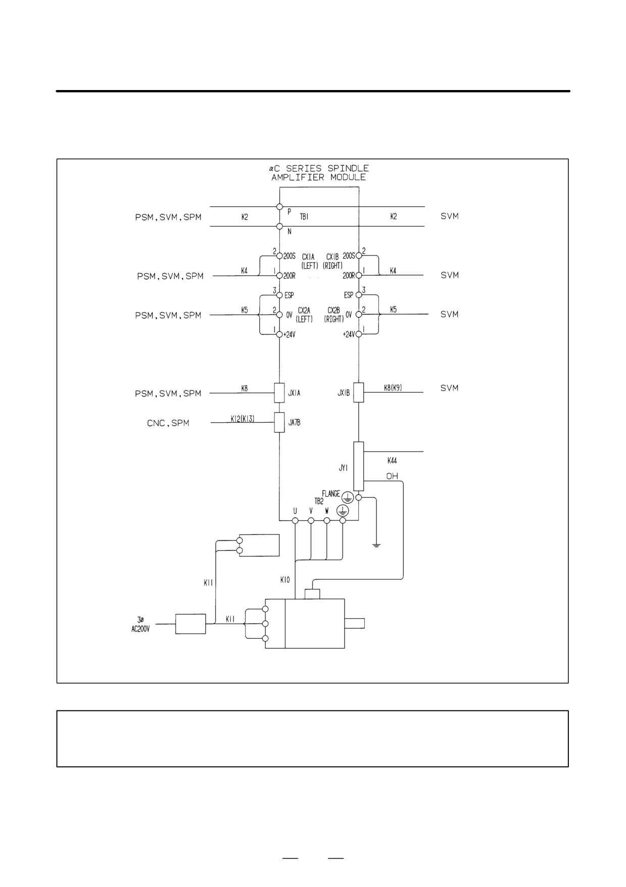
αC series spindle module (SPMC)
(Note1)
(terminating connector)
(Note 2)
Frequency meter, analog override
Cooling
fan
For the
SPMC11 only
Thermostat
Circuit
Spindle
breaker 2
motor
Fan motor
NOTE
1
SPMC15-26
2
Note that the SPMC is not provided with the JA7A (the second spindle connection function).
The connector to be used varies according to the type of the detector being
used. The interfaces for individual detectors are explained separately
later.
277
9. CONNECTION
B-65162E/03
(1) Detailed description of the connection of cable K2
See 9.2.1 (2).
(2) Detailed description of the connection of cable K4
See 9.2.1 (4).
(3) Detailed description of the connection of cable K5
See 9.2.1 (5).
(4) Detailed description of the connection of cable K8
See 9.2.1 (8).
(5) Detailed description of the connection of cable K9
See 9.2.2 (4).
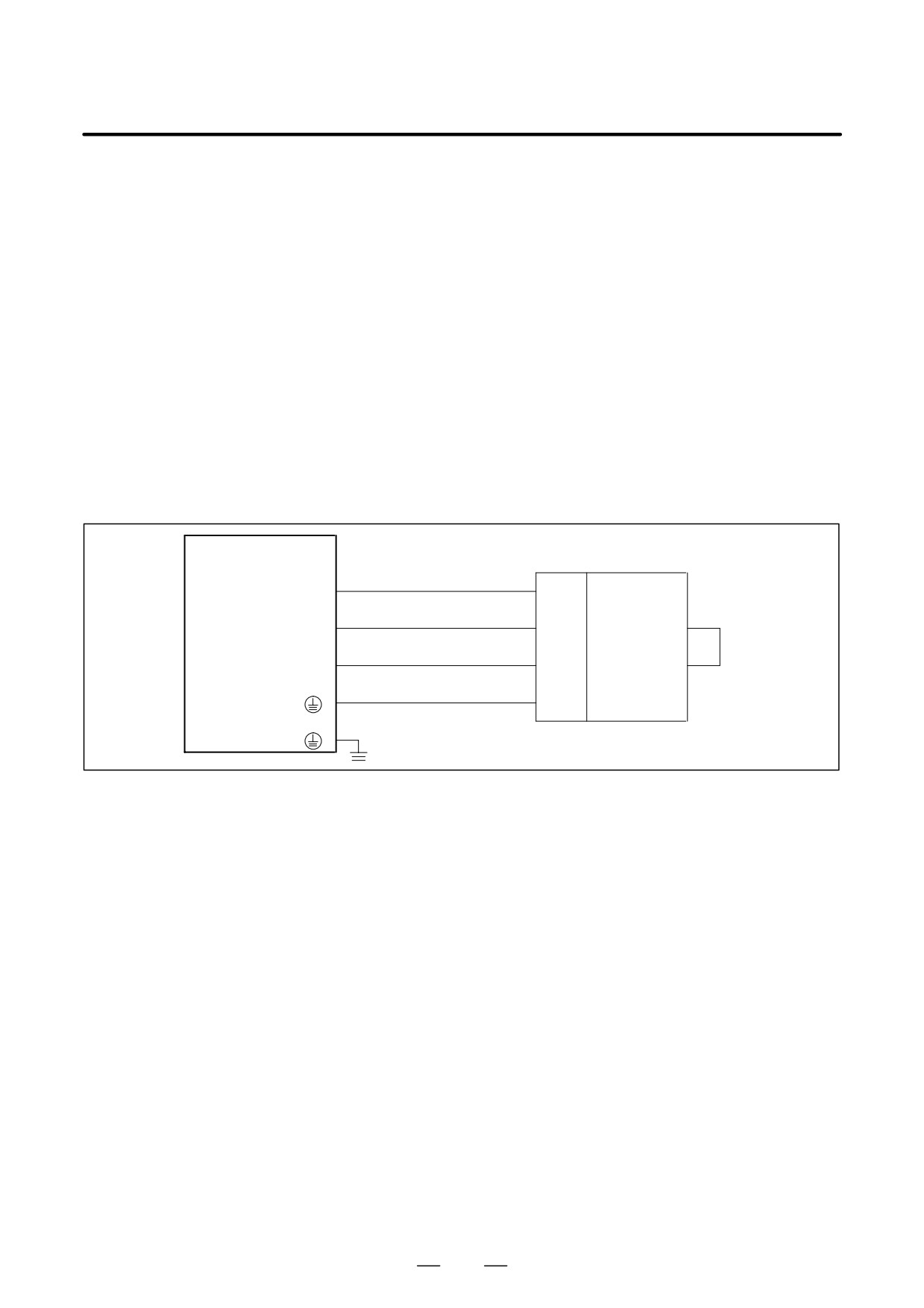
(6) Detailed description of the connection of cable K10 (power line)
SPM
TB2
U
(U)
(U)
V
(V)
(V)
Spindle
W
motor
(W)
(W)
G
(
)
(G)
(
)
278
B-65162E/03
9.CONNECTION
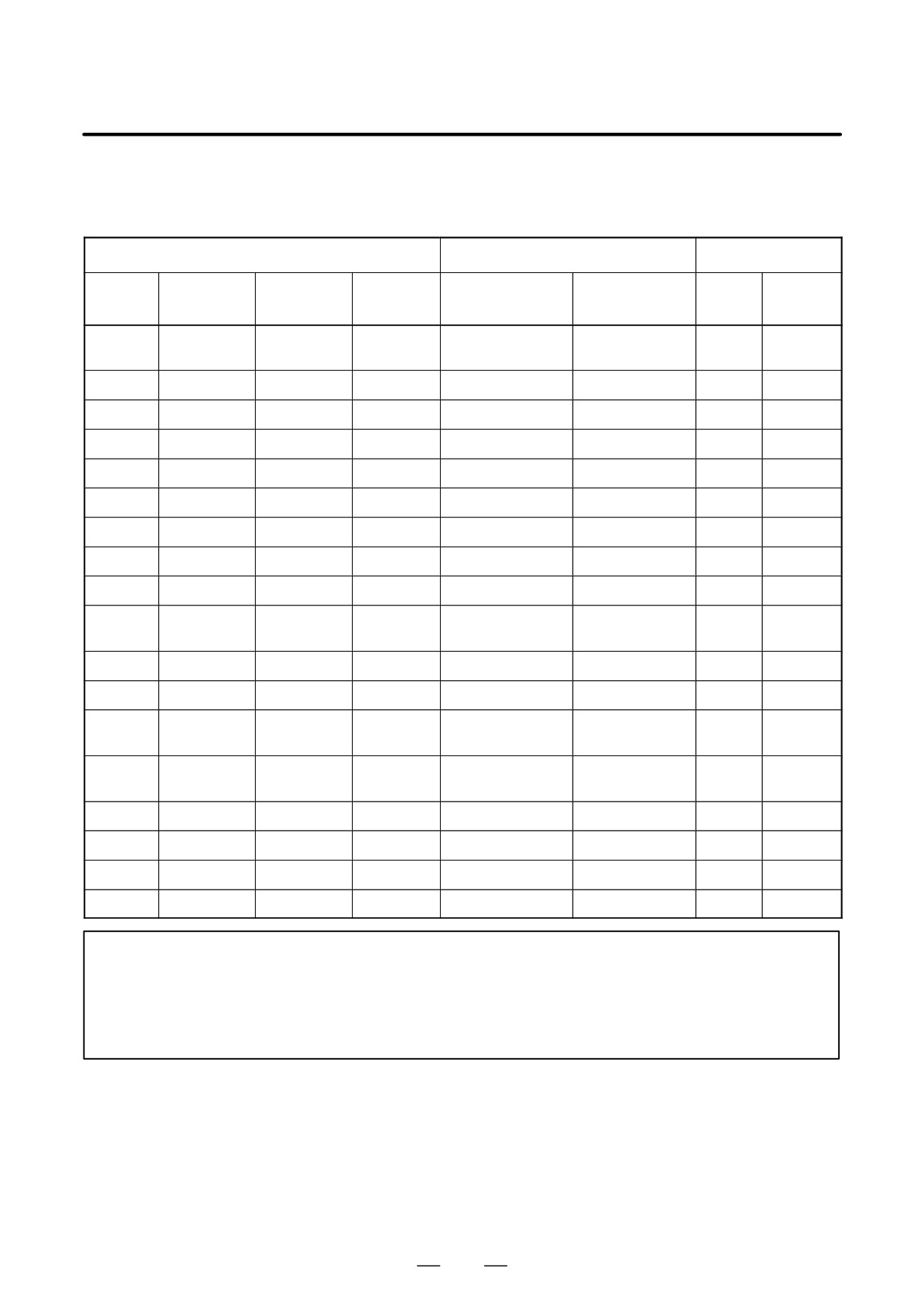
Cables should be connected to the SPM and spindle motor using crimp
terminals that match the motor, as listed in the following table.
Cable K10 (power line) specification
Motor model
Applicable cable
Terminal screw
α (HV)
Heavy-duty pow-
Heat-resistant
Amplifi-
Motor
αseries
αP series
αC series
series
er cable (Note 1)
cable (Note 2)
er side
side
α0.5
---
---
0.75mm2 or larger
---
M4
(Note 3)
---
α1
---
---
αC1
2mm2 or larger
---
M4
M5
α1.5, α2
---
---
αC1.5, αC2
3.5mm2 or larger
3.5mm2 or larger
M4
M5
α3
---
---
αC3
5.5mm2 or larger
3.5mm2 or larger
M4
M5
α6
αP8, αP12
---
αC6
---
3.5mm2 or larger
M4
M5
α8
αP15
---
αC8
---
5.5mm2 or larger
M4
M5
α12
αP18
---
αC12
14mm2 or larger
8mm2 or larger
M6
M5
α15
αP22
---
αC15
---
14mm2 or larger
M6
M5
α18
αP30
---
αC18
---
14mm2 or larger
M6
M8
αP40, αP50,
α22
---
αC22
---
22mm2 or larger
M6
M8
αP60
α30
---
---
---
---
38mm2 or larger
M10
M10
α40
---
---
---
---
50mm2 or larger
M10
M10
α6HV, α8HV,
–--
---
---
---
3.5mm2 or larger
M6
M5
α12HV
α15HV,
–--
---
---
---
5.5mm2 or larger
M6
M5
α18HV
–--
---
α22HV
---
---
8mm2 or larger
M6
M5
–--
---
α30HV
---
---
14mm2 or larger
M6
M10
–--
---
α40HV
---
---
22mm2 or larger
M6
M10
–--
---
α60HV
---
---
50mm2 or larger
M10
M10
NOTE
1
Four-conductor polyvinyl heavy-duty power cable (JIS C3312)
2
Fire-retardant polyflex wire (maximum conductor temperature 105°C) or equivalent to LMFC
manufactured by The Furukawa Electric Co., Ltd.
3
Use the following AMP connector kit: A63L-0001-0428/CT
279
9. CONNECTION
B-65162E/03
(7)
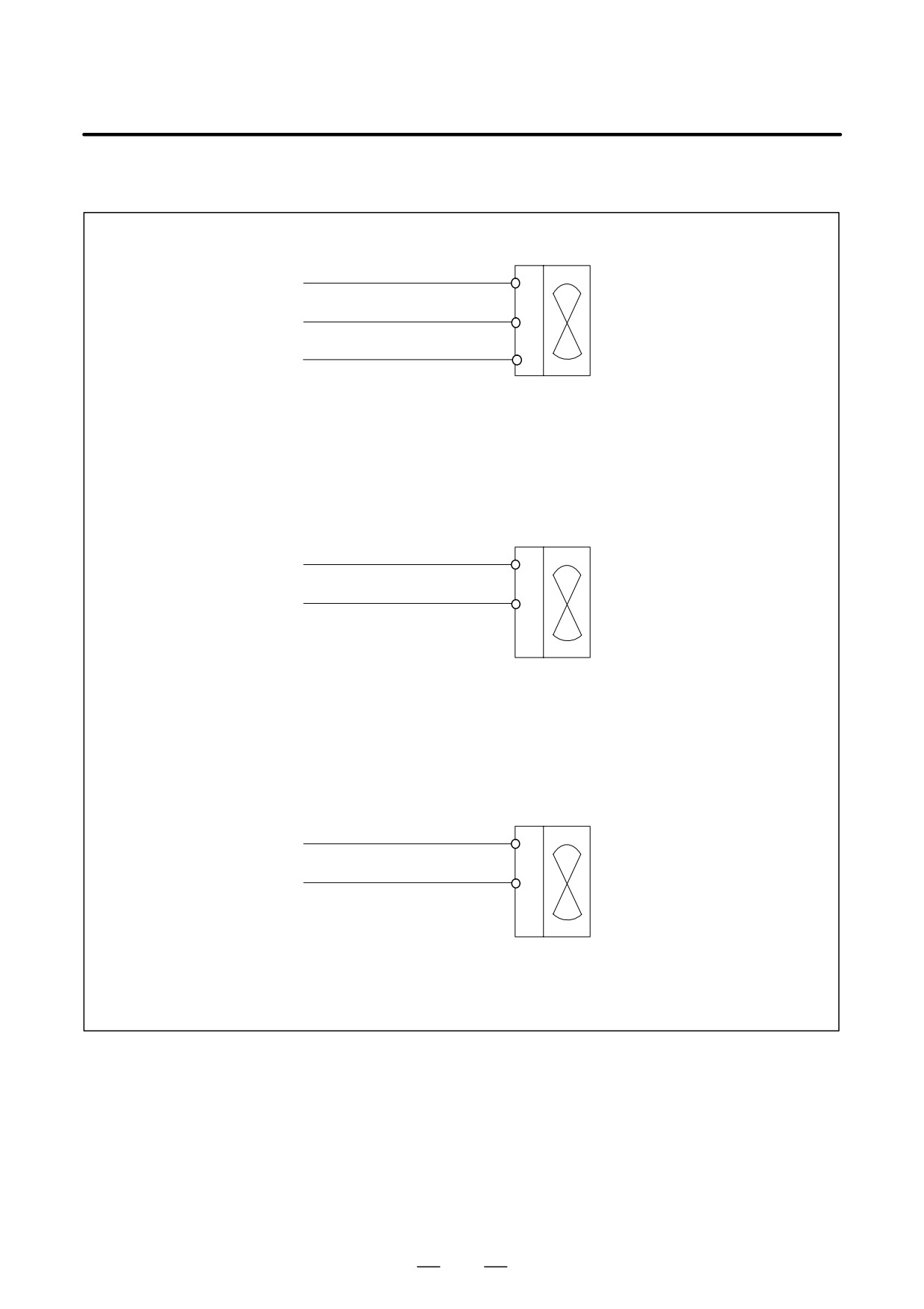
Detailed description of the connection of cable K11
Power for fan motor
200V, three-phase
200R
R
R0
200S
S
S0
Fan motor
200T
T
T0
Cable specification: Use a three-conductor polyvinyl heavy-duty power cable (JIS C3312)
having a conductor size of 2 mm2 or larger.
Fan motor terminal screw: M4
Power for cooling fan (for the SPMC11 only)
200V, single-phase
200R
R
R0
200S
S
S0
Fan motor
Cable specification: Two-conductor polyvinyl heavy-duty power cable (JIS C3312),
conductor size of 1.25 mm2 (50/0.18), PVC sheath 9.6 mm in diameter
Applicable receptacle terminal:
6.3 mm (0.250 in.) series
Power for cooling fan (for the SPM45 and SPM-75HV only)
200V, single-phase
200R
R
R0
200S
S
S0
Fan motor
Cable specification: Two-conductor polyvinyl heavy-duty power cable (JIS C3312),
conductor size of 1.25 mm2 (50/0.18), PVC sheath 9.6 mm in diameter
280
B-65162E/03
9.CONNECTION
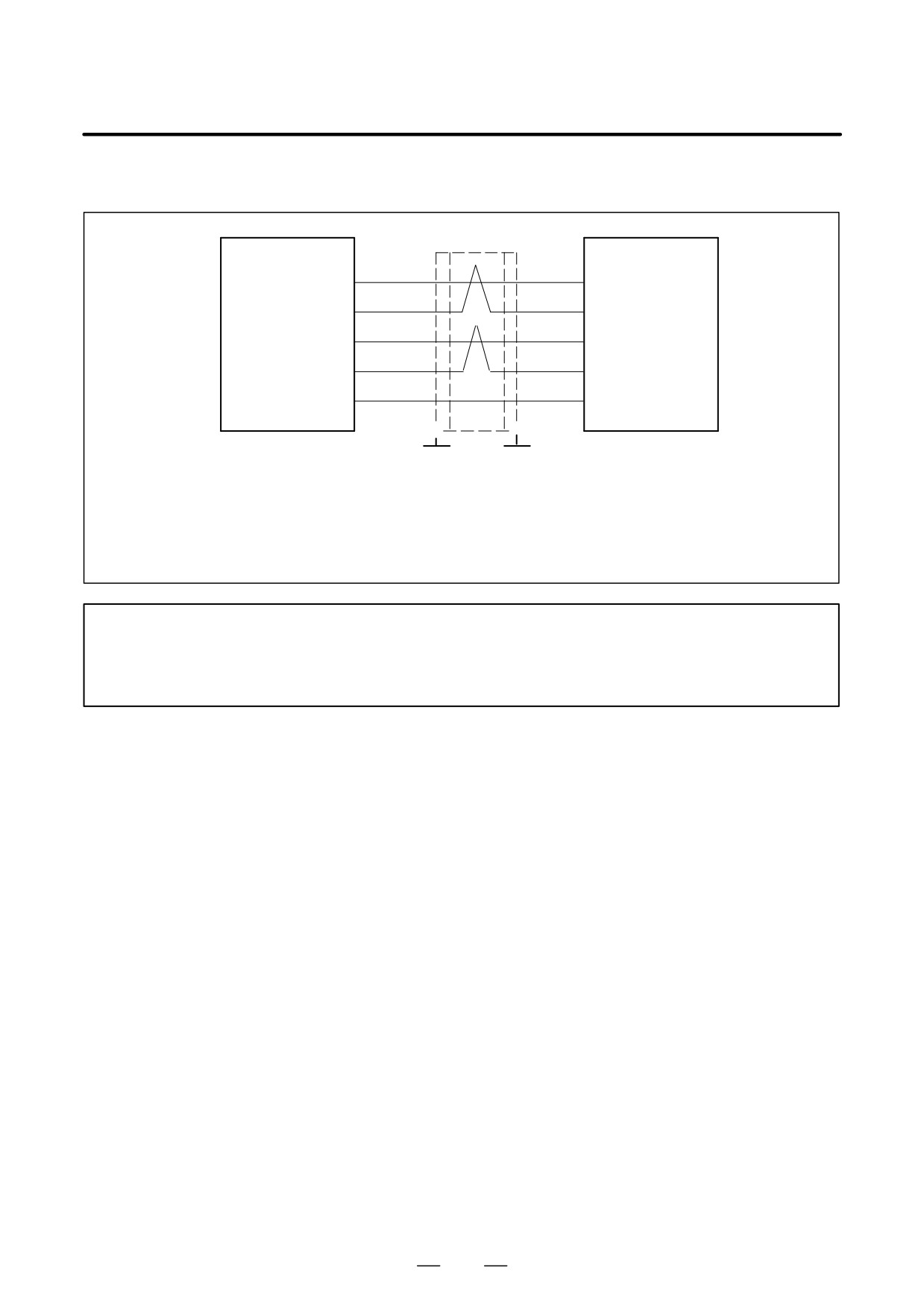
(8) Detailed description of the connection of cable K12
CNC
JA7A
JA7B
SPM
or
or
SOUT
SIN1
(3)
(1)
SIN1
SPM
SPMC
*SOUT
*SIN1
(4)
(2)
*SIN1
SIN
SOUT1
(1)
(3)
SOUT1
*SIN
*SOUT1
(2)
(4)
*SOUT1
0V
0V
(11), (12), (13)
(11), (12), (13)
(14), (15), (16)
(14), (15), (16)
F
F
Required connector
Required connector
Ground plate Ground plate
(HONDA)
(HONDA)
(Note 1)
(Note 1)
Connector PCR-E20FA
Connector PCR-E20FA
Housing
PCR-V20LA
Housing
PCR-V20LA
Cable specification: 0.09 mm2 twisted pair with common shielded
Recommended cable (wire only): A66L-0001-0284#10P
See Appendix C for details.
NOTE
1
If cable K12 is installed near the likes of a power cable, its shielding wire must be connected
to a grounding plate. If an SPM is installed near the CNC or another SPM, however, it is not
necessary to connect the shielding wire to a grounding plate.
281
9. CONNECTION
B-65162E/03
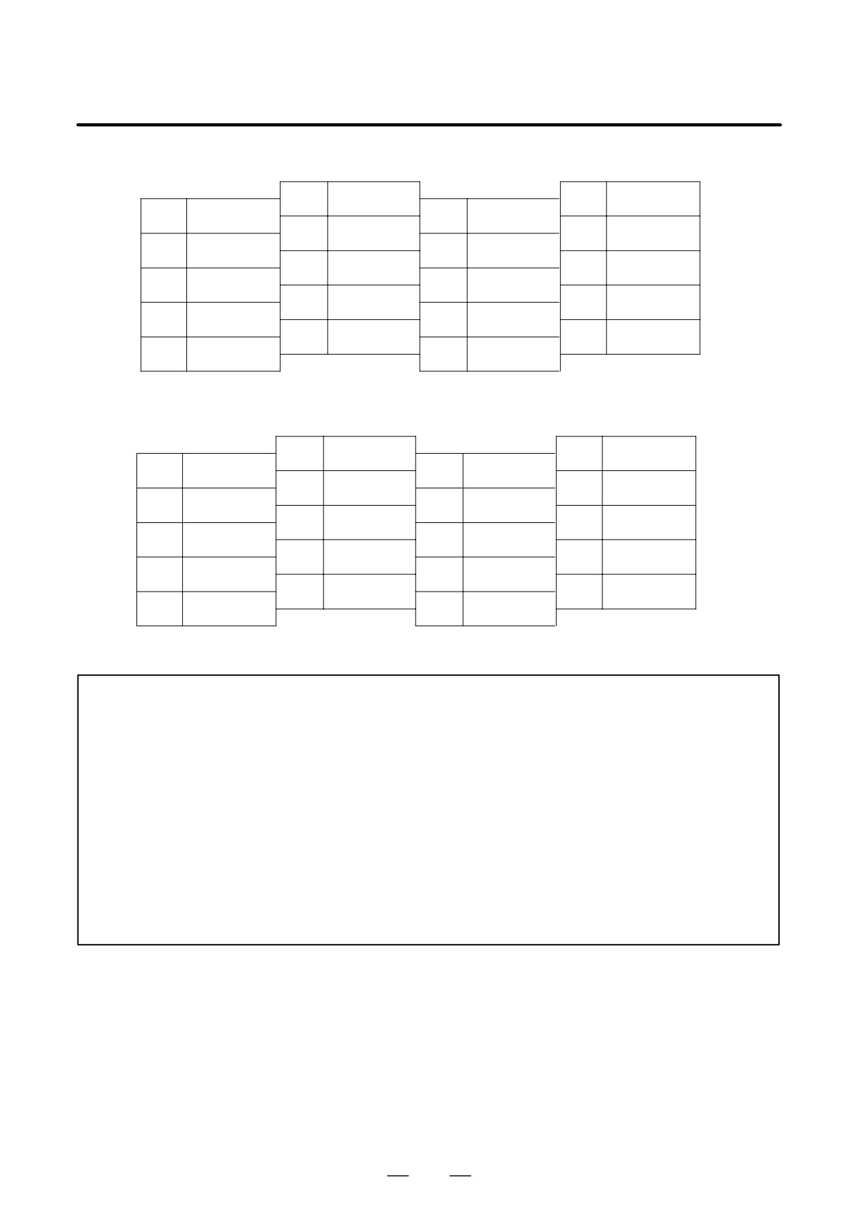
Pin assignment for connector JA7B
10
20
(+5V) Note 2
9
(+5V) Note 2
19
8
18
(+5V) Note 2
7
17
6
16
0V
5
15
0V
4
*SOUT1
14
0V
3
SOUT1
13
0V
2
*SIN1
12
0V
1
SIN1
11
0V
Pin arrangement of the connector on the CNC unit and connector JA7A
10
20
(+5V) Note 2
9
(+5V) Note 2
19
8
18
(+5V) Note 2
7
17
6
16
0V
5
15
0V
4
*SOUT
14
0V
3
SOUT
13
0V
2
*SIN
12
0V
1
SIN
11
0V
NOTE
2
The +5V pin is intended for optical link transmission based on the optical I/O link adapter. Do
not use it when a metal cable is being used; otherwise, the +5 V line of the CNC will be
short-circuited with that of the SPM.
3
SPM serial interface connection using an optical fiber cable
The use of an optical I/O link adapter with the SPM serial interface extends the maximum
allowable length of the optical fiber cable to up to 200 m.
Use optical fiber cables in the following cases:
S When the required cable length is 20 m or longer.
S When the cable must be extended across multiple cabinets, and the cabinets cannot be
connected with a grounding wire 5.5 mm2 or larger.
S The cable may be affected by noise, for example, if the cable is laid near a strong magnetic
noise source like a welding machine or in parallel with a power line over a long distance.
282
B-65162E/03
9.CONNECTION
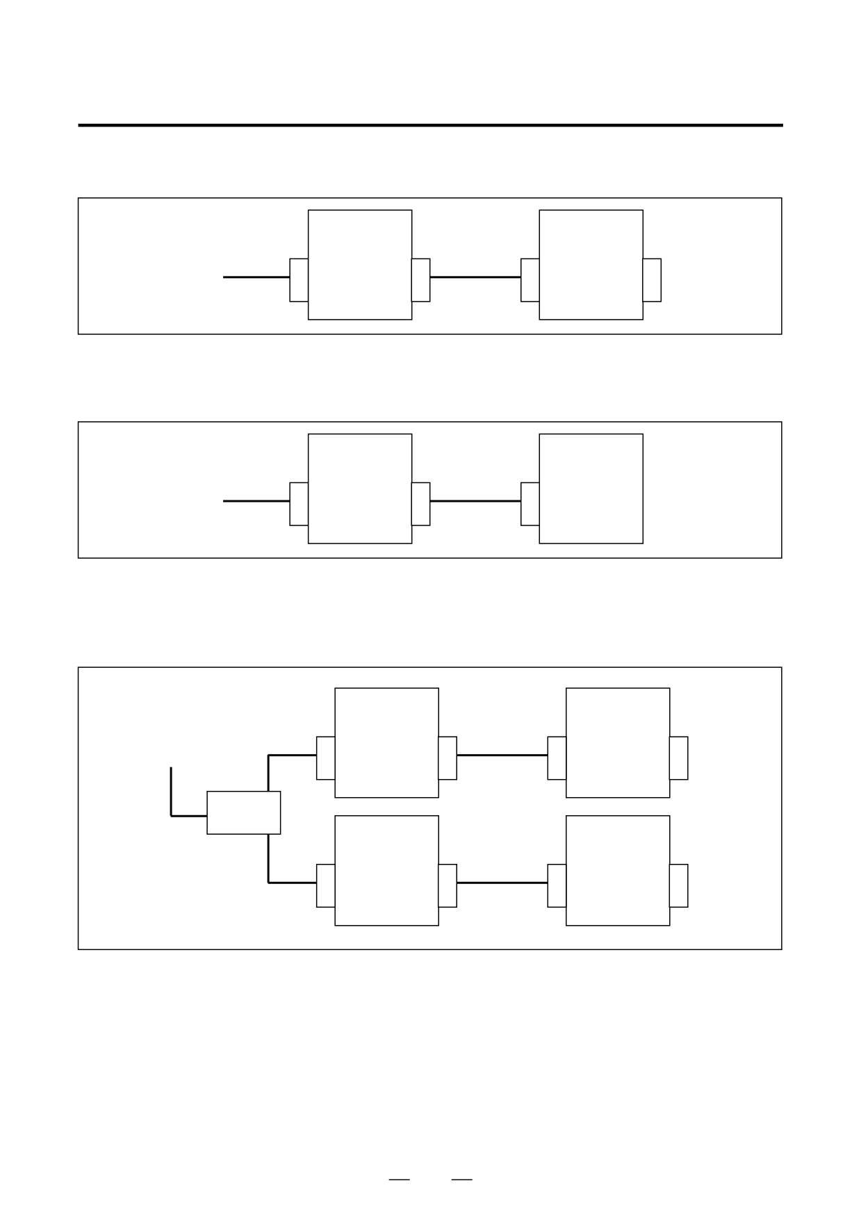
– Electrical interface connection between two SPM units
SPM
SPM
JA7B
JA7A
JA7B
JA7A
CNC
JA7A
K12
K12
JA7B
– Electrical interface connection from the SPM to the SPMC
Cable K12 cannot be used to make a reverse connection (from the SPMC to the SPM).
SPM
SPM
JA7B
JA7A
JA7B
CNC
JA7A
K12
K12
JA7B
– Electrical interface connection between four SPM units in i series
Refer to the applicable CNC connection manual or technical report A-73123-014JA for a detailed description
of the serial spindle connector panel.
SPM
SPM
JA7B
JA7A
JA7B
JA7A
CNC
JA41
K12
K12
JA7A-1
Serial
JA48
spindle con-
nector panel
SPM
SPM
JA7A-2
JA7B
JA7A
JA7B
JA7A
K12
K12
283
9. CONNECTION
B-65162E/03
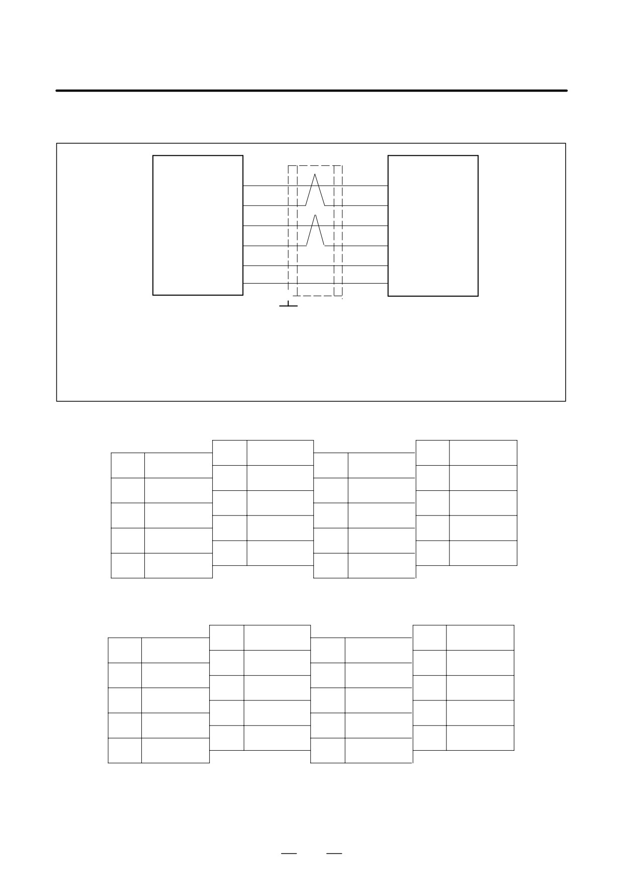
(9) Detailed description of the connection of cable K13
CNC
JA7A
Optical I/O link
or
(JA7B)
adapter
SPM
(3)
SOUT
SIN1
(2)
SIN
*SOUT
*SIN1
(4)
(1)
*SIN
SIN
SOUT
(1)
(4)
SOUT
*SIN
*SOUT
(2)
(3)
*SOUT
+5V
+5V
(9),
(18), (20)
(9), (18), (20)
0V
0V
(11), (12), (13)
(11), (12), (13)
(14), (15), (16)
(14), (15), (16)
F
Required connector
Required connector
Grounding plate
(HONDA)
(HONDA)
Connector PCR-E20FA
Connector PCR-E20FA
Housing
PCR-V20LA
Housing
PCR-V20LA
Cable specification: 0.09 mm2 twisted pair with common shielded
Recommended cable (wire only): A66L-0001-0284#10P
See Appendix C for details.
Pin assignment for connector JA7A
10
20
+5V
9
+5V
19
8
18
+5V
7
17
6
16
0V
5
15
0V
4
*SOUT
14
0V
3
SOUT
13
0V
2
*SIN
12
0V
1
SIN
11
0V
Pin arrangement of the connector on the optical I/O link adapter side
10
20
+5V
9
+5V
19
8
18
+5V
7
17
6
16
0V
5
15
0V
4
SOUT
14
0V
3
*SOUT
13
0V
2
SIN
12
0V
1
*SIN
11
0V
284
B-65162E/03
9.CONNECTION
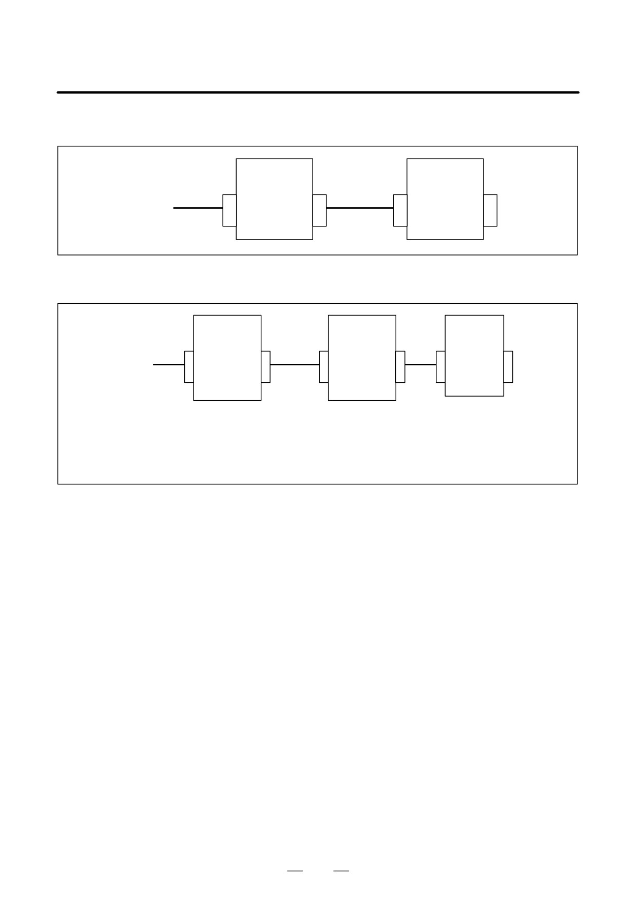
– Connection with the FS0 or FS15A
I/O link adapter
SPM
COP1
JD1
JA7B
JA7A
FS0,FS15A
A13B-0154-B001
COP5
Optical
K13
cable
- Connection in which the required cable length is 20 m or more and in which an optical fiber cable is used
I/O link adapter
I/O
link adapter
SPM
JD1
COP1
COP1
JD1 JA7B
JA7A
CNC
A13B-0154-B001
A13B-0154-B001
JA7A
K13
Optical
K13
JA7B
cable
The specification drawing number of the optical fiber cable shown
above is as follows:
A66L-6001-0009#LjjR003
(jj represents a cable length, such as 5, 10, 15, 20, 30, 40, 50,
60, 80, 90, or 100 m.)
285
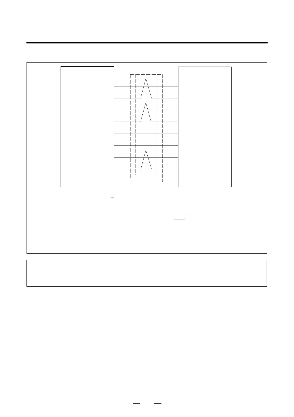
9. CONNECTION
B-65162E/03
(10) Detailed description of connection of cable K14
SPM
JY2
M sensor
Motor
(pulse generator)
PA
PA
(A2)
(5)
RA
RA
(6)
(B2)
PB
PB
(A3)
(7)
RB
RB
(8)
(B3)
+5V
+5V
(A1)
(9), (18), (20)
0V
0V
(12), (14), (16)
(B5)
OH1
OH1
(13)
(A6)
OH2
OH2
(15)
(B6)
SS
SS
(10)
F
F
(A5)
Required connector (AMP)
Required connector
Connector housing 178289-6
Connector FI40B-20S
FI40B-20S-CV5
Contact 1-175217-2
Housing
FI-20-CV5
Cable specification : Three
0.18mm2
twisted pairs
Common shielded cable
Two
0.5mm2
wires
Cable:
+5V, 0V...0.5 mm2
PA, RA, PB, RB, OH1, OH2...0.18 mm2
twisted pair
Recommended cable (wire only): A66L-0001-0368
See Appendix C for details.
NOTE
Connect pin 16 to a 0 V potential; otherwise, a sensor may be damaged if the cable is attached
to connector JY3 and power is supplied.
286
B-65162E/03
9.CONNECTION
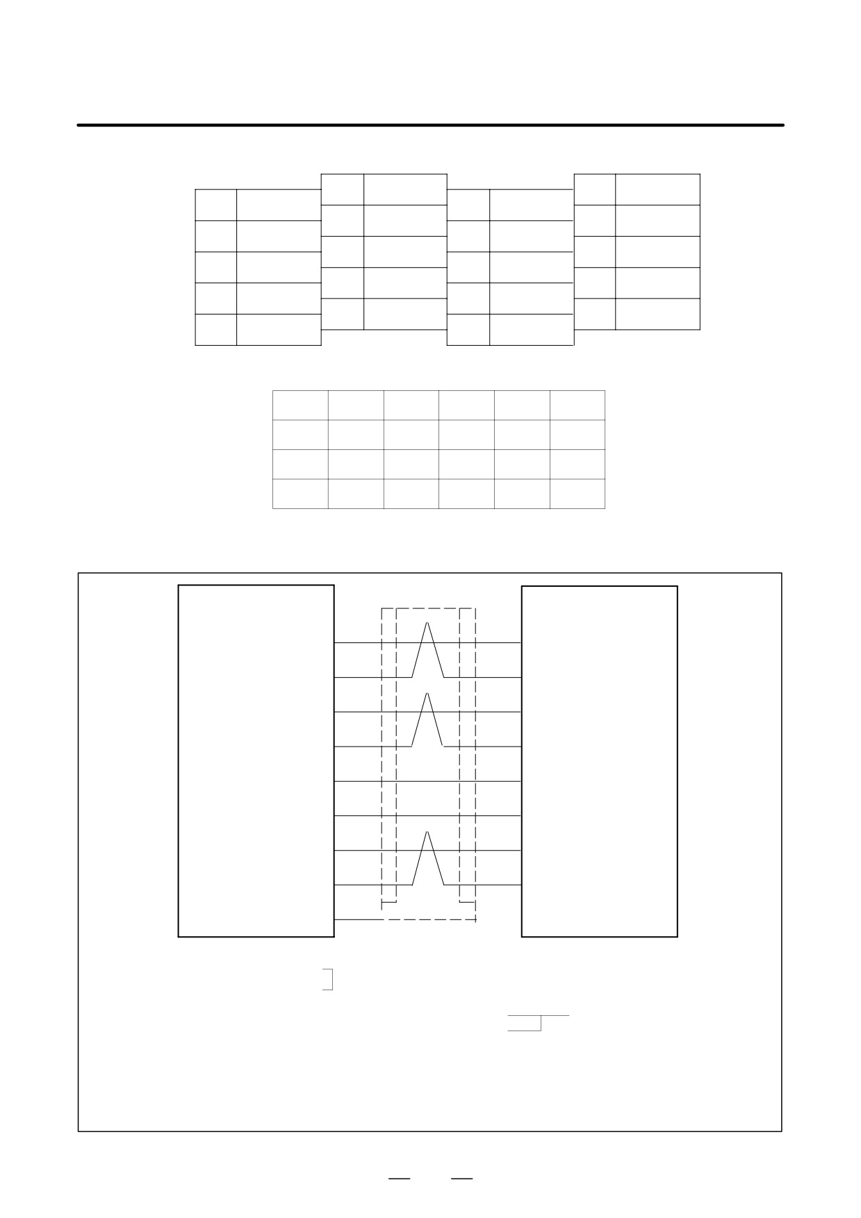
Pin assignment of connector JY2
10
SS
20
+5V
9
+5V
19
8
RB
18
+5V
7
PB
17
6
RA
16
0V
5
PA
15
OH2
4
14
0V
3
13
OH1
2
12
0V
1
11
Pin arrangement of the AMP connector on the motor side
B1
B2
B3
B4
B5
B6
RA
RB
0V
OH2
A1
A2
A3
A4
A5
A6
+5V
PA
PB
SS
OH1
(11) Detailed description of connection of cable K14 (for spindle motor α0.5)
SPM
JY2
M sensor
Motor
(pulse generator)
PA
PA
(05)
(5)
RA
RA
(6)
(20)
PB
PB
(09)
(7)
RB
RB
(8)
(08)
+5V
+5V
(23)
*
(9), (18), (20)
0V
0V
(12), (14), (16)
(16)
OH1
OH1
(13)
(13)
OH2
OH2
(15)
(03)
SS
(10)
F
F
Required connector (Hirose Electric Co., Ltd.)
Required connector (Hirose Electric Co., Ltd.)
Connector
HDBB-25S
Connector FI40B-20S
FI40B-20S-CV5
Contactor cover GDBW-25-CV
Housing
FI-20-CV5
Cable specification : Three
0.18mm2
twisted pairs
Common shielded cable
Two
0.5mm2
wires
Cable:
+5V, 0V...0.5 mm2
PA, RA, PB, RB, OH1, OH2...0.18 mm2
twisted pair
Recommended cable (wire only): A66L-0001-0368
See Appendix C for details.
287
9. CONNECTION
B-65162E/03
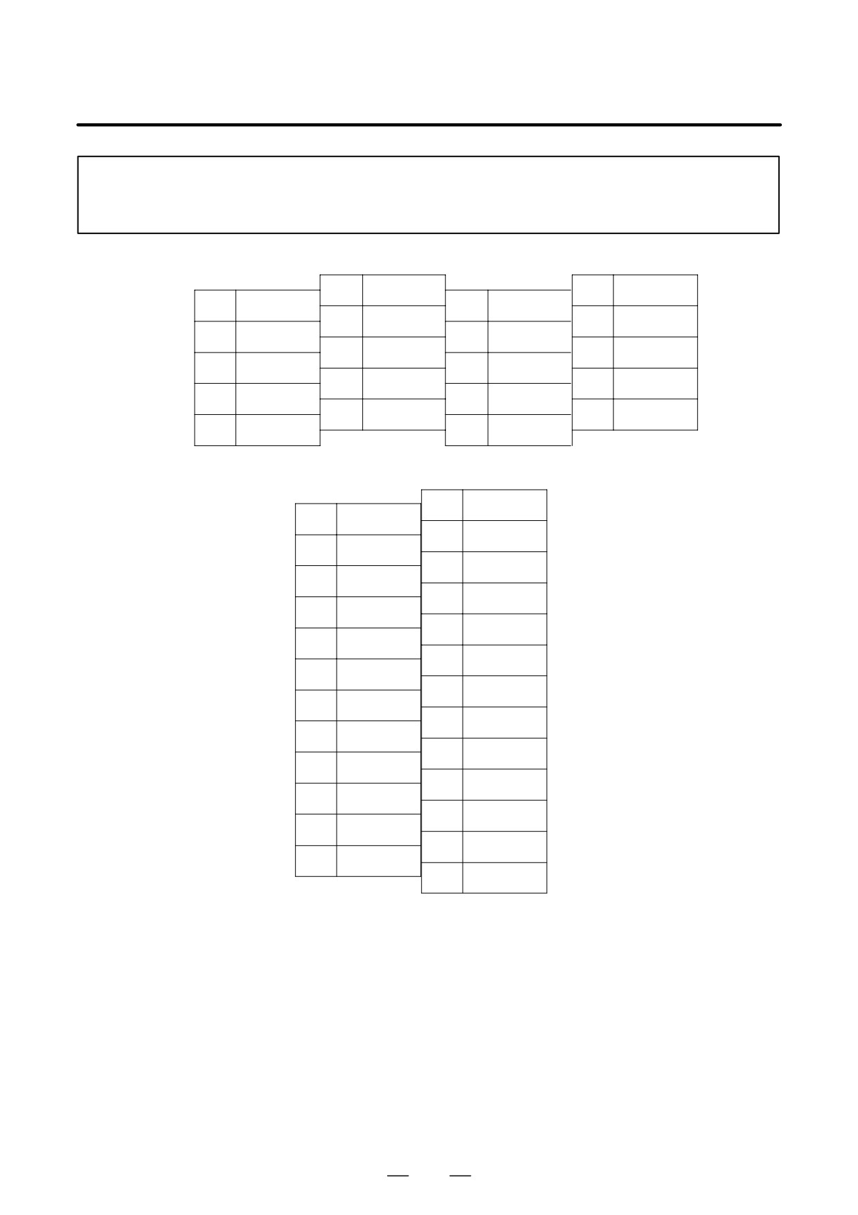
NOTE
Connect pin 16 to a 0 V potential; otherwise, a sensor may be damaged if the cable is attached
to connector JY3 and power is supplied.
Pin arrangement of connector JY2
10
SS
20
+5V
9
+5V
19
8
RB
18
+5V
7
PB
17
6
RA
16
0V
5
PA
15
OH2
4
14
0V
3
13
OH1
2
12
0V
1
11
Pin arrangement of the connector on the motor side
01
14
02
15
03
OH2
16
0V
04
17
05
PA
18
06
19
07
20
RA
08
RB
21
09
PB
22
10
23
+5V
11
24
12
25
13
OH1
288
B-65162E/03
9.CONNECTION
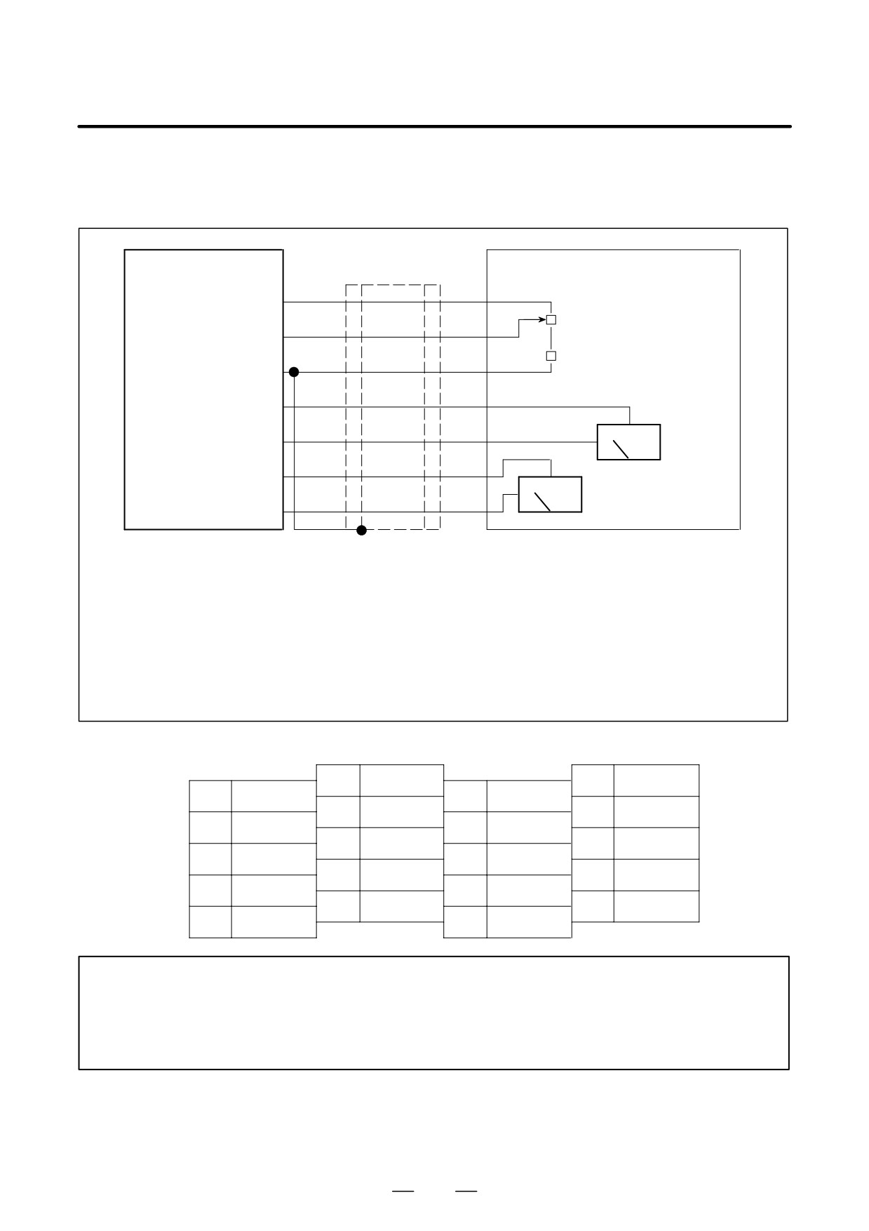
(12) Detailed description of connection of cable K33
(a) Use for load meter or speedometer
Power magnetics cabinet
SPM
JY1
OVR1
Can be overridden in 1 %
(1)
steps, using the variable
OVR2
VR
resistor (Note 1).
(2)
R1
0V
(20)
LM
(16)
0M
(18)
Load meter
SM
(17)
Speedometer
0M
(19)
Required connector (HONDA)
Required connector (HONDA)
Connector PCR-E20FS
Connector PCR-E20FA
Housing
PCR-V20LA
Housing
PCR-V20LA
(solder type)
Cable specification: 0.09mm2
common shielded cable
Recommended cable (wire only): A66L-0001-0284#10P
See Appendix C for details.
Connect the shielded wire to a 0 V potential (pin 20).
Pin assignment of connector JY1
10
20
0V
9
*(Note 2)
19
0M
8
18
0M
7
17
SM
6
16
LM
5
15
4
14
3
13
2
OVR2
12
1
OVR1
11
*
NOTE
1
Select such an external resistance such that VR + R1 falls within the range between 2 kΩ and
10 kΩ .
2
Pins indicated * are intended to input or output signals used on a spindle check board. Do not
connect any other signal line to them.
289
9. CONNECTION
B-65162E/03
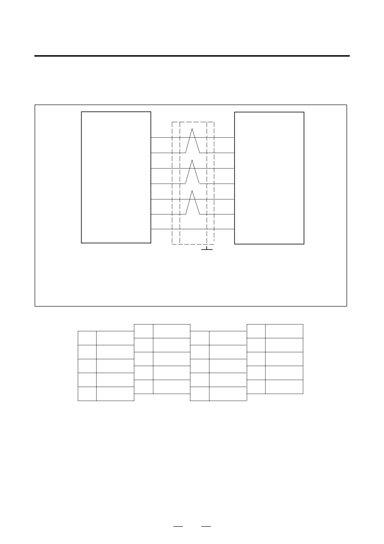
(13) Detailed description of connection of cable K36
(a) Use for position coder signals (equivalent to the output of line
driver 75113)
SPM
JX4(JY9)
CNC or power
magnetics cabinet
PA
(5)
*PA
(6)
PB
(7)
*PB
(8)
SC
(1)
*SC
(2)
0V
(12), (14), (16)
F
Required connector (HONDA)
Grounding plate
Connector PCR-E20FA
Housing
PCR-V20LA
Cable specification: 0.09mm2
common shielded cable
Recommended cable (wire only): A66L-0001-0284#10P
See Appendix C for details.
Pin assignment of connector JY4 (JY9)
10
20
9
19
8
*PB
18
7
PB
17
6
*PA
16
0V
5
PA
15
4
14
0V
3
13
2
*SC
12
0V
1
SC
11
290
B-65162E/03
9.CONNECTION
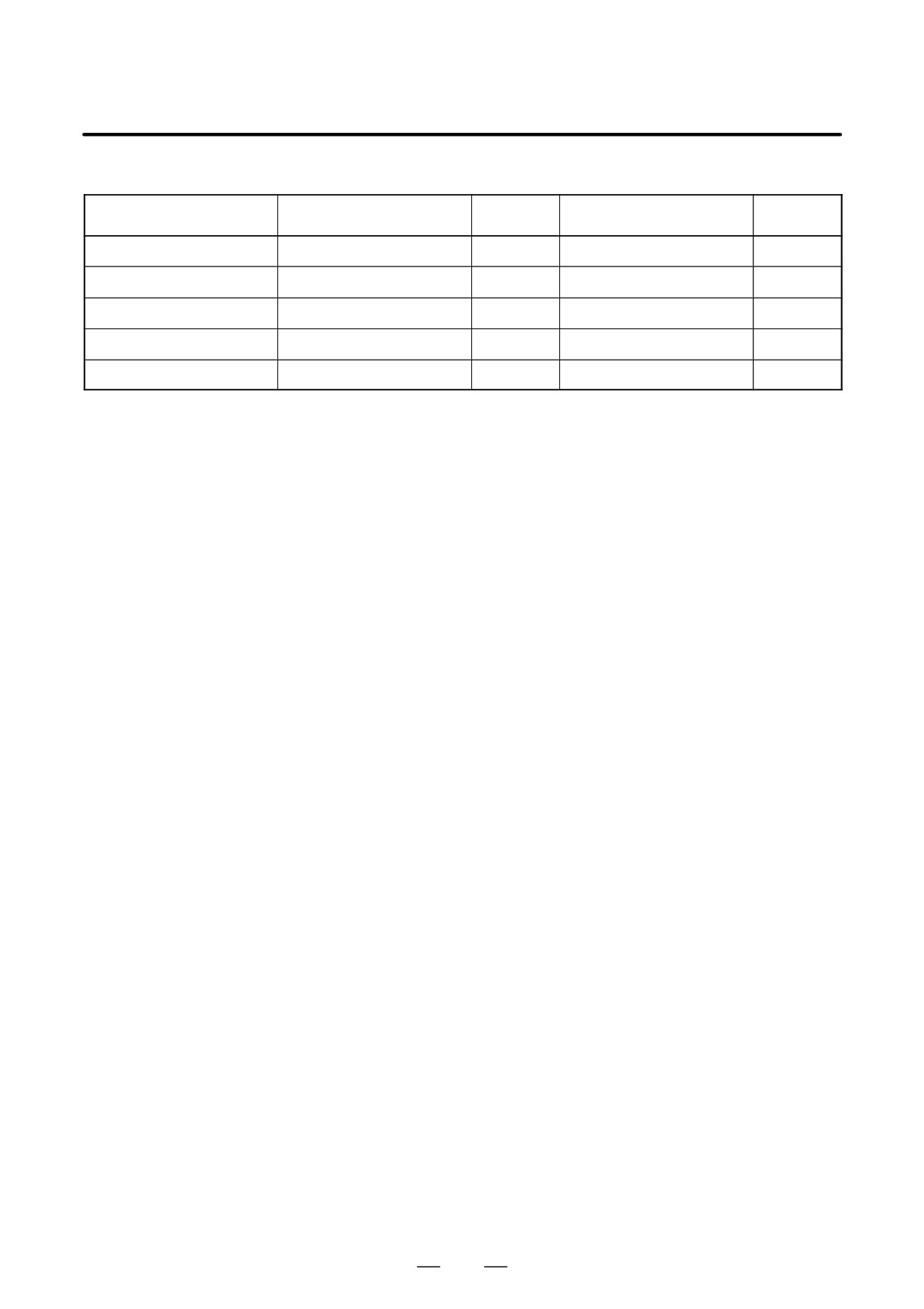
Output connector of each SPM model
Specification drawing
Specification drawing
Model
Connector
Connector
number (old model)
number (current model)
SPM-2.2 to 11 (TYPE 1)
---
---
A06B-6078-H2**#H500
JX4
SPM-15 to 30 (TYPE 1)
A06B-6078-H2**#H500
---
A06B-6088-H2**#H500
JX4
SPM-2.2 to 11 (TYPE 2)
---
---
A06B-6078-H3**#H500
JX4
SPM-15 to 30 (TYPE 2)
A06B-6078-H3**#H500
JY9
A06B-6088-H3**#H500
JX4
SPM-11 to 30 (TYPE 3)
A06B-6078-H4**#H500
JY9
A06B-6088-H4**#H500
JX4
Usually, position coder signals are sent serially. So, K36 need not be
connected.
K36 is used for position coder signals in a unit (for example, PMC or
speed difference control unit) other than the CNC.
291
9. CONNECTION
B-65162E/03
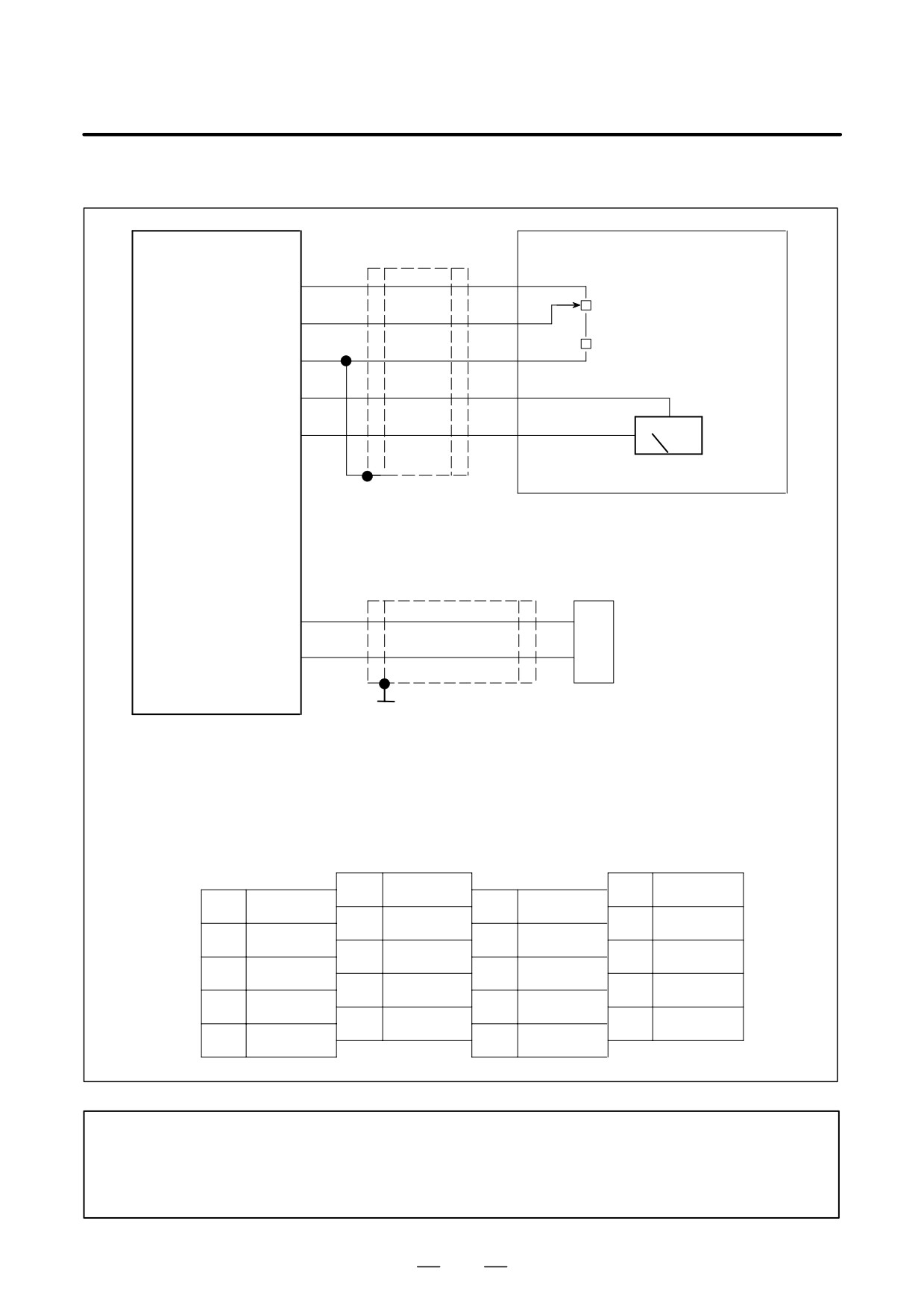
(14) Detailed description of the connection of cable K44
Power magnetics cabinet
SPMC
JY1
OVR1
(1)
Can be overridden in 1 %
OVR2
VR
steps, using the variable
(2)
resistor (Note 1)
0V
R1
(20)
SM
(17)
0M
(19)
Speedometer (or load meter)
Cable specification: 0.09 mm2
Required connector (HONDA)
common shielded cabl
Connector PCR-E20FA
Recommended cable
Housing
PCR-V20LA
specification :
A66L-0001-0284#10P
OH1
A6
(6)
Motor
TH
OH2
B6
thermostat
(8)
Grounding plate
Required connector
Cable specification: 0.18 mm2
Required connector (AMP):
(HIROSE)
common shielded cable
Supplied with the module
Connector FI40B-20S
Recommended cable
Housing
178289-6
specification :
Contact
1-175217-2
Housing
FI-20-CV5
A66L-0001-0275
Pin assignment of connector JY1
10
20
0V
9
* (Note 2)
19
0M
8
OH2
18
0M
7
17
SM
6
OH1
16
5
15
4
14
3
13
2
OVR2
12
1
OVR1
11
NOTE
1
Select an external resistance such that VR + R1 falls within the range between 2kΩ and 10kΩ.
2
Pins indicated * are intended to input or output signals used on a spindle check board. Do not
connect any other signal line to them.
292
B-65162E/03
9.CONNECTION
Pin arrangement of AMP connector on the motor side
B1
B2
B3
B4
B5
B6
OH2
A1
A2
A3
A4
A5
A6
OH1
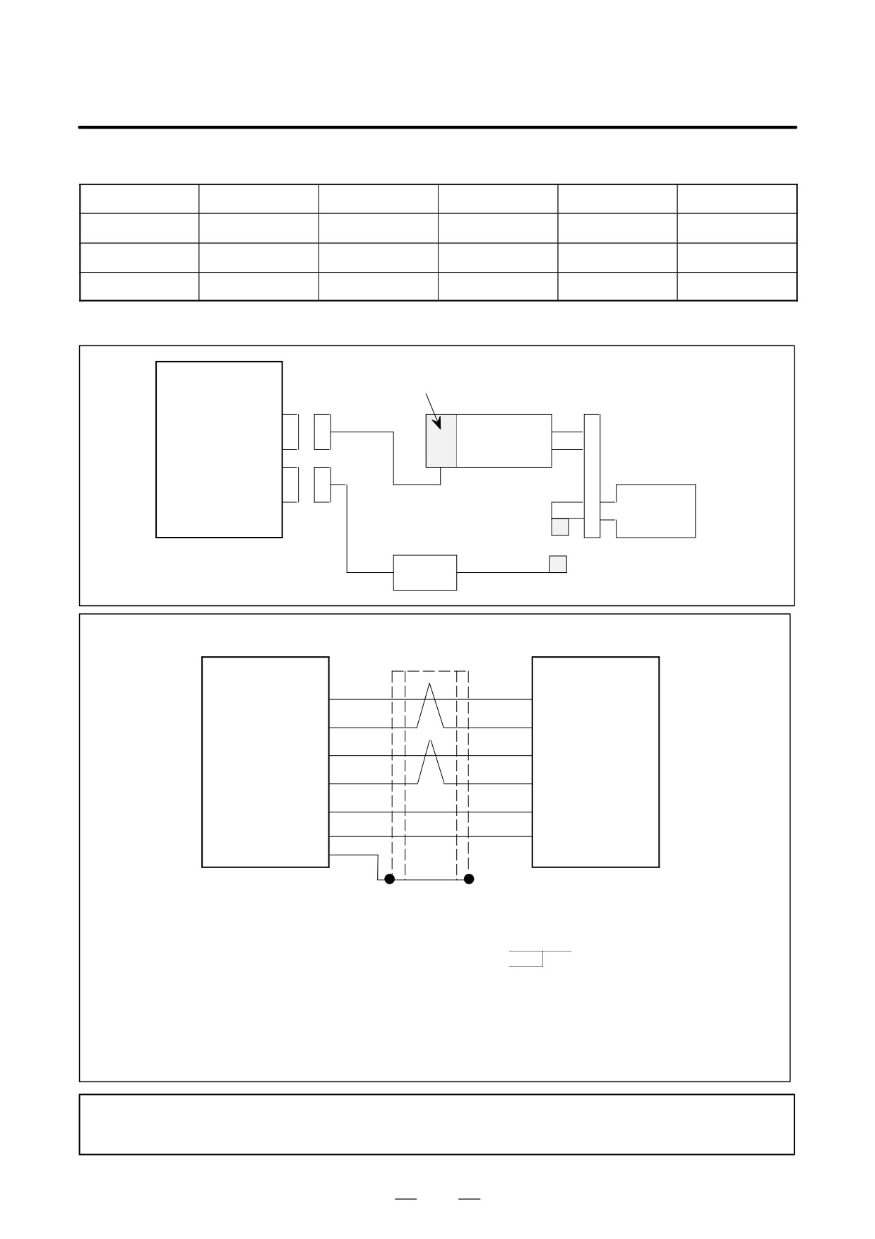
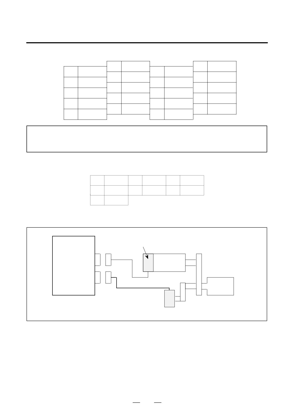
(15) Combined use of the M sensor (pulse generator) and magnetic sensor
SPM
M sensor (pulse generator)
TYPE I
K14
JY2
Spindle motor
JY3
Spindle
K15
Magnetic sensor amplifier
Magnetic sensor
Detailed description of the connection of cable K15
Magnetic sensor
SPM
JY3
amplifier
MSA
(5)
(A)
MSB
(14)
(D)
LSA
(1)
(F)
LSB
(3)
(E)
+15V
(12)
(C)
0V
* (7), (16)
(B)
SS
(10)
Required connector
Supplied connector
(HIROSE)
metal receptacle
Connector FI40A-2015S
Housing
FI-20-CV
Cable specification : Three
0.18mm2
twisted pairs
Common shielded cable
Two
0.5mm2
wires
Cable:
+15V, 0V...0.5 mm2 (for 0V, any one of those indicated *)
MSA, MSB, LSA, LSB...0.18 mm2 twisted pair
Recommended cable: A66L-0001-0286
See Appendix C for details.
Connect the shielded wire to SS (pin 10).
NOTE
Use the supplied rubber sleeve to eliminate any gap between the cable and connector.
293
9. CONNECTION
B-65162E/03
Pin assignment of connector JY3
10
SS
20
9
19
8
18
(EXTSC)
7
0V
17
6
16
0V
5
MSA
15
4
14
MSB
3
LSB
13
(PU/PD)
2
12
+15V
1
LSA
11
(+24V)
NOTE
Pin 11 of connector JY3 outputs +24 V. If a sensor is connected to it, the sensor may be
damaged. Before supplying power, make sure that the sensor is not connected to +24 V.
Pin arrangement of the metal receptacle
A
MSA
B
0V
C
+15V
D
MSB
E
LSB
F
LSA
G
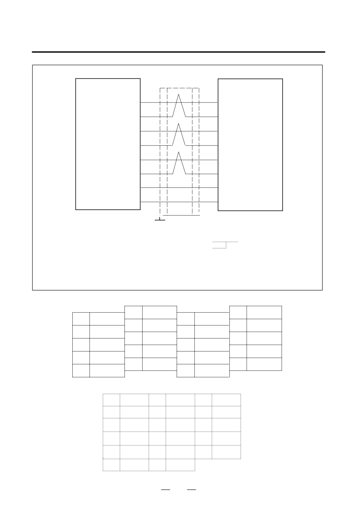
(16) Combined use of the M sensor (pulse generator) and position coder
SPM
M sensor (pulse generator)
TYPE I
K14
JY2
Spindle motor
JY4
K16
Spindle
Position coder
294
B-65162E/03
9.CONNECTION
Detailed description of the connection of cable K16
SPM
JY4
Position coder
PAE
PA
(A)
(5)
*PAE
*PA
(6)
(N)
PBE
PB
(C)
(7)
*PBE
*PB
(8)
(R)
PSE
PZ
(1)
(B)
*PSE
*PZ
(2)
(P)
5V
+5V
(9), (18), (20)
(H)
0V
0V
* (12), (14), (16)
(K)
Required connector
F
F
Required connector
(HIROSE)
Canon connector
Grounding plate
Connector FI40-2015S
MS3106B20-29S
Housing
FI-20-CV
Cable specification : Three
0.18mm2
twisted pairs
Common shielded cable
Two
0.5mm2
wires
Cable:
+5V, 0V...0.5 mm2 (any one of those indicated *)
PAE, *PAE, PBE, *PBE, PSE, *PSE...0.18 mm2
twisted pair
Recommended cable: A66L-0001-0286
See Appendix C for details.
Pin arrangement of connector JY4
10
20
5V
9
5V
19
18
5V
8
*PBE
7
PBE
17
6
*PAE
16
0V
5
PAE
15
4
14
0V
3
13
2
*PSE
12
0V
1
PSE
11
Pin arrangement of the connector on the position coder side
A
PA
B
PZ
C
PB
D
E
F
G
H
+5V
J
K
0V
L
M
N
*PA
P
*PZ
R
*PB
S
T
295
9. CONNECTION
B-65162E/03
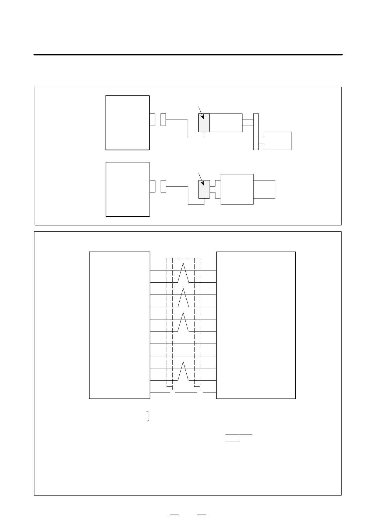
(17) Combined use of the MZ and BZ sensors (built-in sensors)
Example 1)
SPM
MZ sensor (built-in sensor)
TYPE 1
K17
JY2
Spindle
motor
Spindle
Example 2)
SPM
BZ sensor (built-in sensor)
TYPE 1
K17
JY2
Built-in
spindle
Spindle
motor
Detailed descriptions of the connection of cable K17 (for motor incorporating an MZ sensor)
SPM
JY2
Motor
(Motor incorporating an MZ sensorr)
PA
VA
(5)
(A2)
When AMP connector
is used
*PA
*VA
(6)
(B2)
PB
VB
(7)
(A3)
*PB
*VB
(8)
(B3)
MZ
VZ
(1)
(A4)
*MZ
*VZ
(2)
(B4)
+5V
+5V
* (9), (18), (20)
(A1)
0V
0V
* (12), (14), (16)
(B5)
OH1
OH1
(13)
(A6)
OH2
OH2
(15)
(B6)
SS
SS
(10)
F
F
(A5)
Required connector (HIROSE)
Required connector (AMP)
Connector FI40B-20S
Connector
178289-6
FI40B-20S-CV5
Housing
FI-20-CV5
Contact
1-175217-2
Cable specification : Four
0.18mm2
twisted pairs
Common shielded cable
Two
0.5mm2
wires
Cable:
+5V, 0V...0.5 mm2 (if any pin indicated * is to be used, use pin 16 so that the
sensor can be protected against burn-out resulting from incorrect connection.)
PA, *PA, PB, *PB, MZ, *MZ, OH1, OH2...0.18 mm2 twisted pair
Recommended cable: A66L-0001-0368
See Appendix C for details.
296
B-65162E/03
9.CONNECTION
Pin arrangement of connector JY2
10
SS
20
+5V
9
+5V
19
8
*PB
18
+5V
7
PB
17
6
*PA
16
0V
5
PA
15
OH2
4
14
0V
3
13
OH1
2
*MZ
12
0V
1
MZ
11
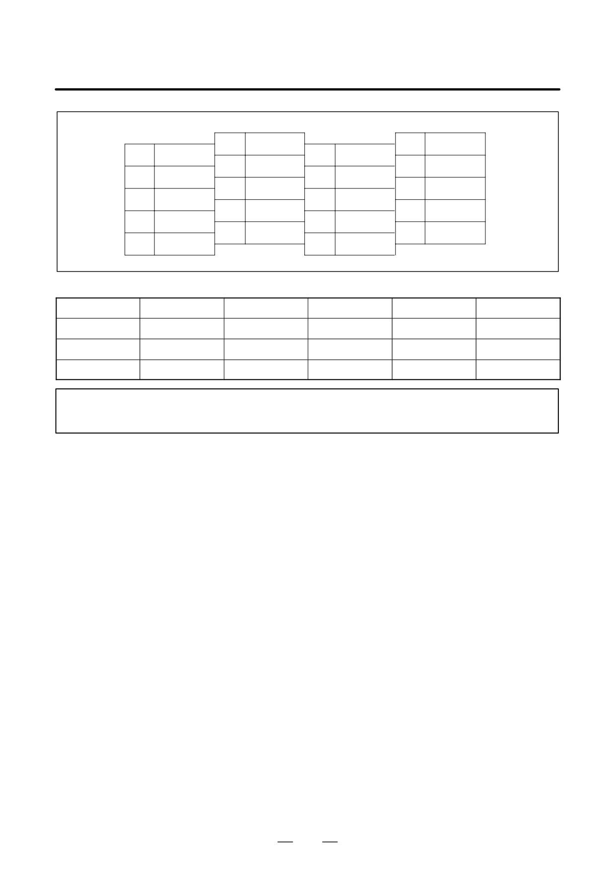
Pin arrangement of the AMP connector on the MZ sensor (built-in sensor) side
B1
B2
B3
B4
B5
B6
*VA
*VB
*VZ
0V
OH2
A1
A2
A3
A4
A5
A6
+5V
VA
VB
VZ
SS
OH1
NOTE
If the sensor is connected to other connector, it may be damaged when the power is supplied.
297
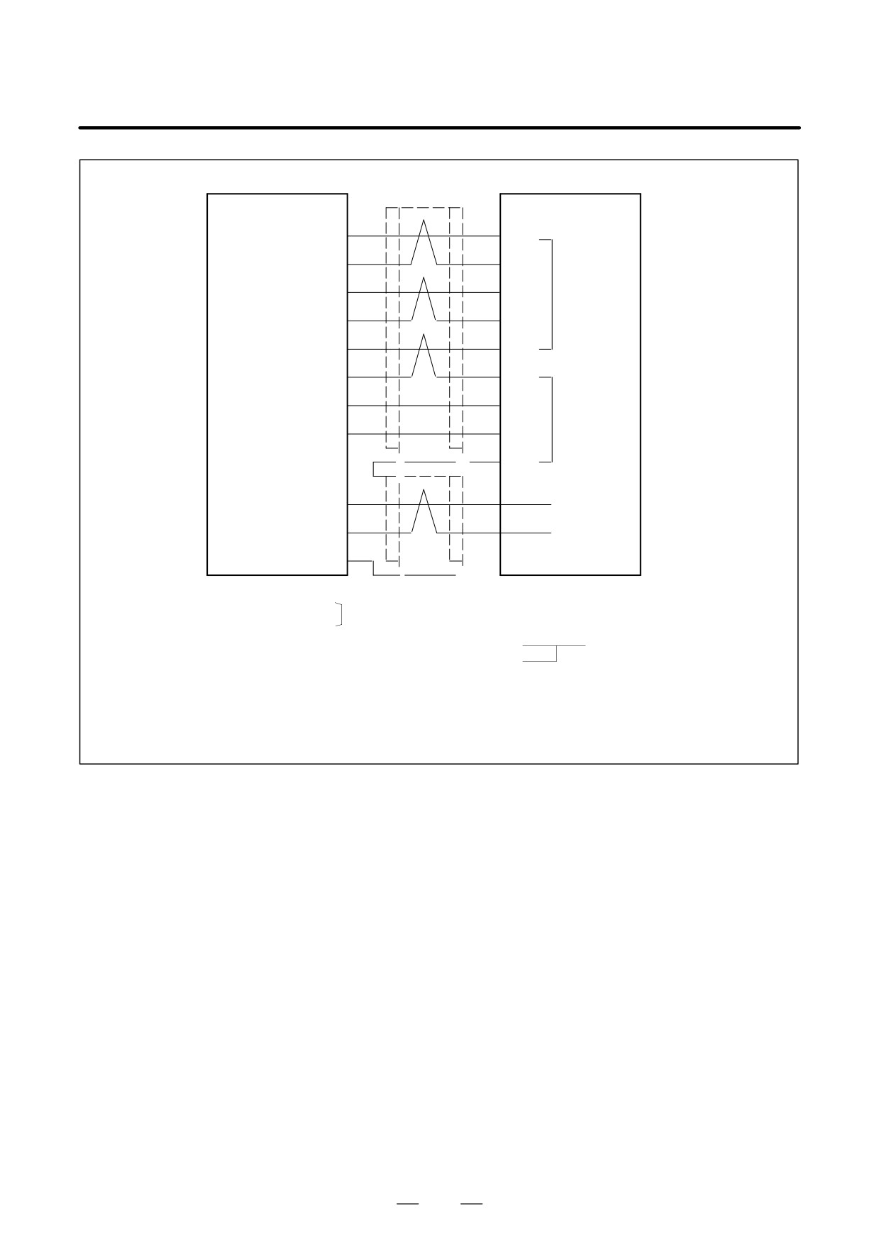
9. CONNECTION
B-65162E/03
Detailed description of the connection of cable K17 (connection of a built-in motor) without using an
AMP connector
SPM
JY2
Motor
If no AMP connector
PA
VA
(5)
(5)
is used
*PA
*VA
(6)
(2)
PB
VB
(7)
(6)
CN1
*PB
*VB
(8)
(3)
*MZ
*VZ
(2)
(1)
MZ
VZ
(1)
(2)
+5V
+5V
* (9), (18), (20)
(4), (1)
CN2
0V
0V
* (12), (14), (16)
(6), (3)
SS
F
F
(5)
F
OH1
OH1
(13)
OH2
OH2
Thermostat
(15)
SS
(10)
F
F
Required connector (HIROSE)
Cable specification: (HONDA)
Connector FI40B-20S
Connector Z-374
FI40B-20S-CV5
Housing
FI-20-CV5
Contact
HKP-F413
Cable specification : Four
0.18mm2
twisted pairs
Common shielded cable
Two
0.5mm2
wires
(Note)
Cables used : +5V, 0V…0.18mm2
(for any one of the three pins indicated with *)
PA, *PA, PB, *PB, MZ, *MZ, OH1, OH2…0.18mm2
twisted pair
Recommended cable (without shield) : A66L-0001-0367
See Appendix C for details.
298
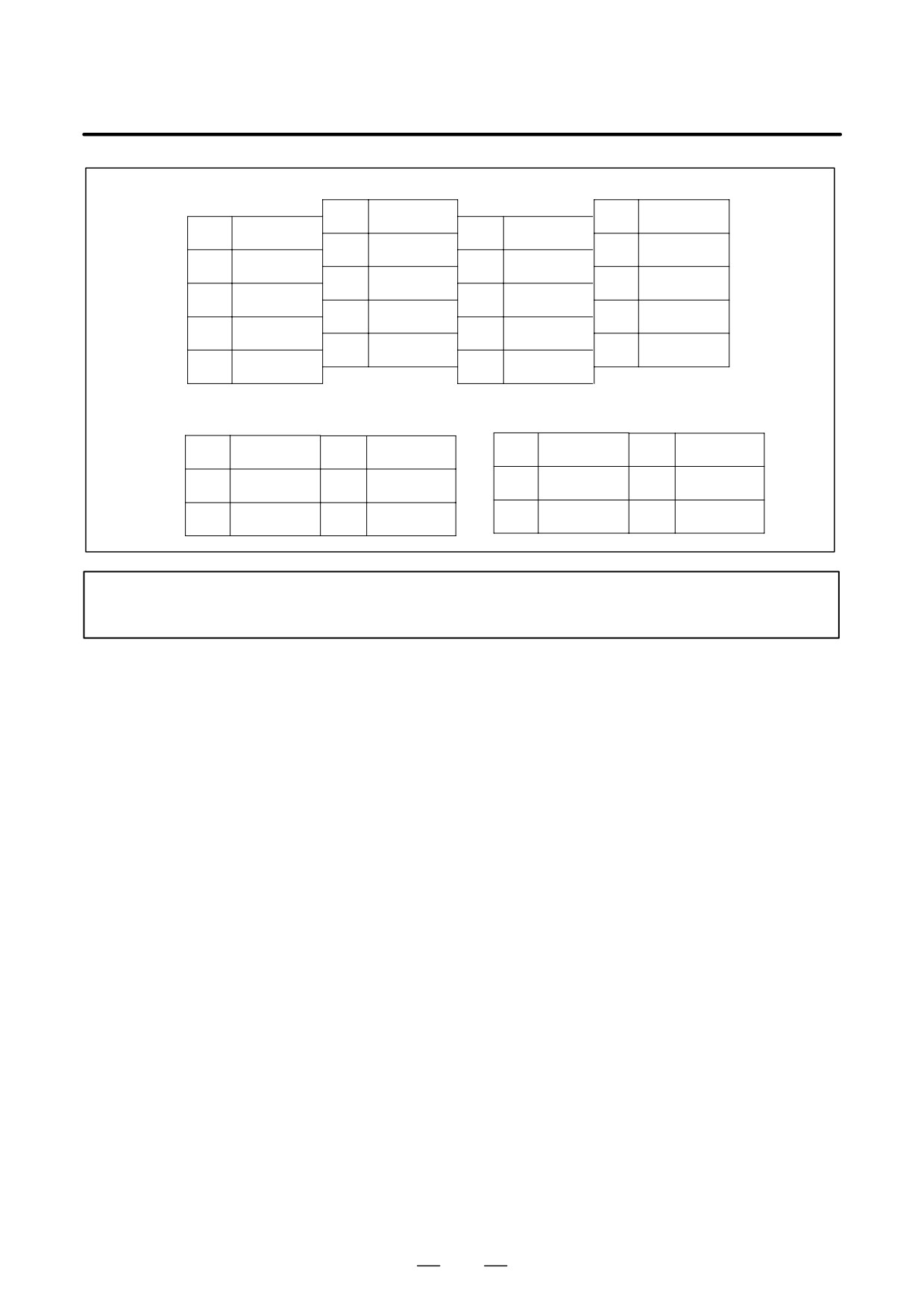
B-65162E/03
9.CONNECTION
Pin arrangement of connector JY2
10
SS
20
+5V
9
+5V
19
8
*PB
18
+5V
7
PB
17
6
*PA
16
0V
5
PA
15
OH2
4
14
0V
3
13
OH1
2
*MZ
12
0V
1
MZ
11
Connector CN1
Connector CN2
1
(5V)
5V
1
*MZ
4
4
2
*VA
5
VA
2
VZ
5
SS
3
*VB
6
VB
3
(0V)
6
0V
NOTE
If the sensor is connected to other connector, it may be damaged when the power is supplied.
299
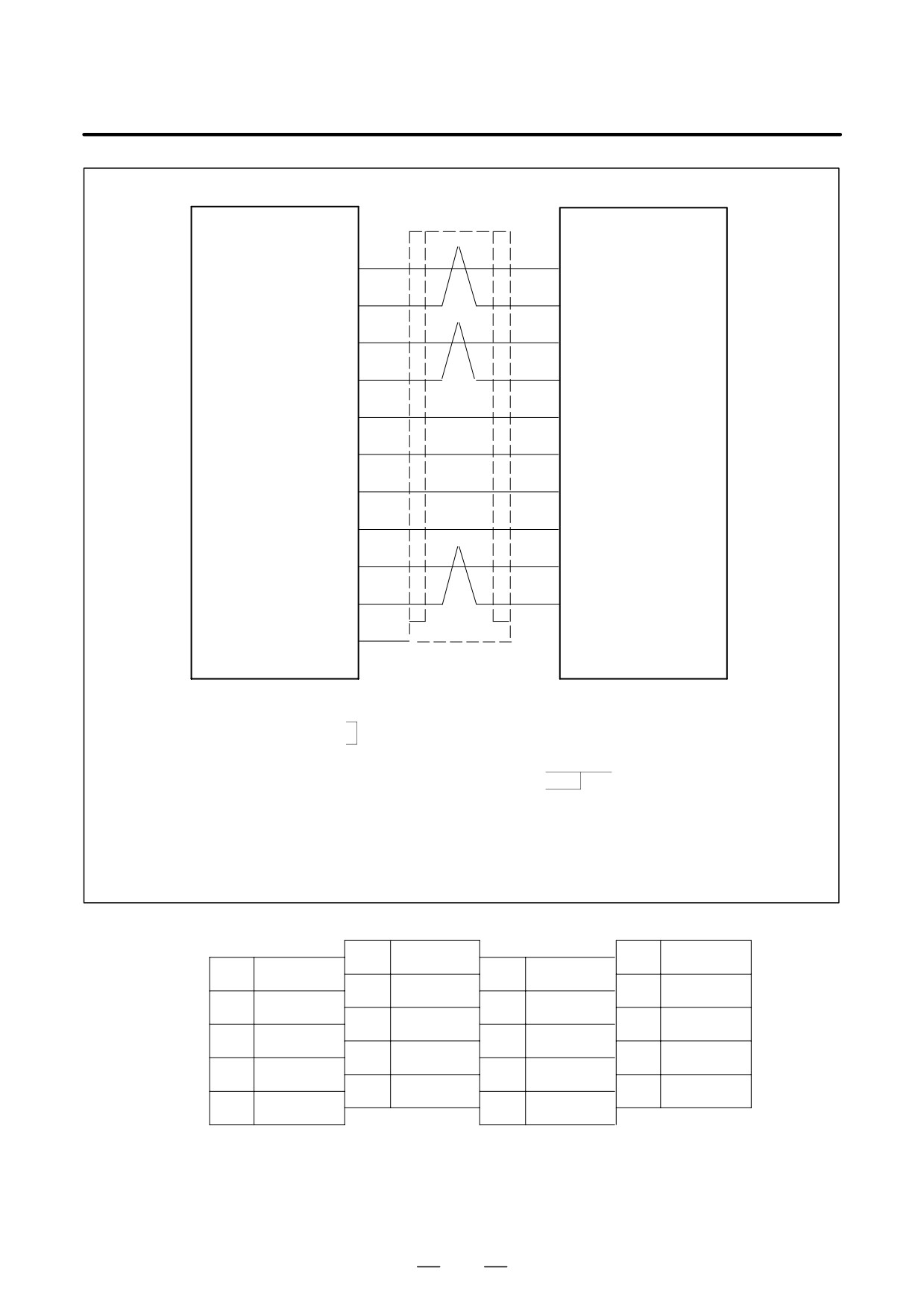
9. CONNECTION
B-65162E/03
Detailed description of the connection of cable K17 (connection of spindle motor α0.5)
SPM
JY2
Motor
(motor incorporating an
PA
VA
MZ sensor)
(09)
(5)
*PA
*VA
(6)
(08)
PB
VB
(07)
(7)
*PB
*VB
(8)
(06)
MZ
VZ
(05)
(1)
*MZ
*VZ
(2)
(20)
+5V
+5V
* (9), (18), (20)
(12), (25) *
0V
0V
* (12), (14), (16)
(03), (16) *
OH1
OH1
(13)
(01)
OH2
OH2
(15)
(11)
SS
(10)
F
F
Required connector (HIROSE)
Required connector (HIROSE)
Connector
HDBB-25S
Connector FI40B-20S
FI40B-20S-CV5
Contactor cover GDBW-25-CV
Housing
FI-20-CV5
Cable specification : Four
0.18mm2
twisted pairs
Common shielded cable
Two
0.5mm2
wires
Cable:
+5V, 0V...0.5 mm2 (if pins indicated by * are to be used, use pins 16, 14, and 12 in the
stated order so that the sensor is protected against burn-out resulting from incorrect connection.
Recommended cable: A66L-0001-0368
See Appendix C for details.
Pin arrangement of connector JY2
10
SS
20
+5V
9
+5V
19
8
*PB
18
+5V
7
PB
17
6
*PA
16
0V
5
PA
15
OH2
4
14
0V
3
13
OH1
2
12
0V
*MZ
1
MZ
11
300
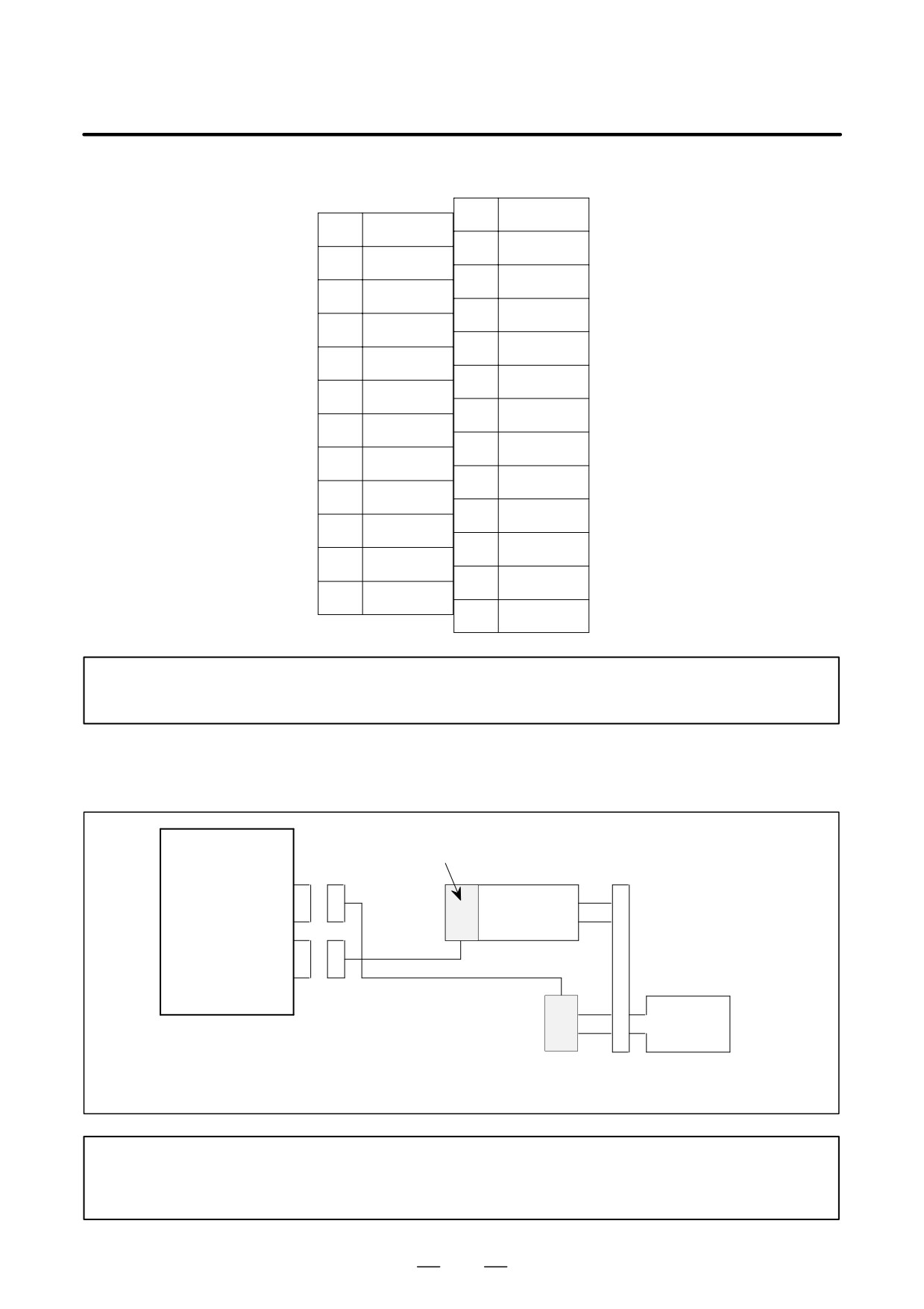
B-65162E/03
9.CONNECTION
Pin arrangement of the connector on the motor side
01
OH1
14
02
15
03
0V
16
0V
04
17
05
VZ
18
06
*VB
19
07
VB
20
*VZ
08
*VA
21
09
VA
22
10
23
11
OH2
24
12
+5V
25
+5V
13
NOTE
If the sensor is connected to other connector, it may be damaged when the power is supplied.
(18) Combined use of the M sensor (pulse generator) and BZ sensor (separate built-in sensor)
SPM
M sensor (pulse generator)
TYPE 2
JY2
Spindle motor
K14
JY5
K17
(Note)
BZ sensor
Spindle
(built-in sensor)
If the BZ sensor is to be wired as shown above, such that it uses only the position coder signal, a different connec-
tor is required. No change is made to the specification of cables K14 or K17.
NOTE
If the BZ sensor is to be wired as shown above, such that it uses only the position coder signal,
neither OH1 or OH2 of cable K17 need be connected.
301
9. CONNECTION
B-65162E/03
(19) Use of high-resolution magnetic pulse coder (with motor only)
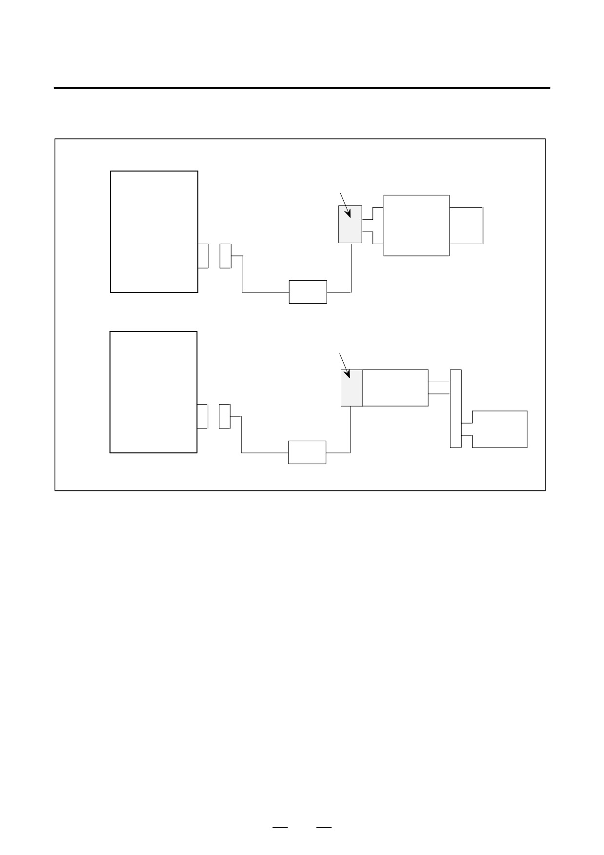
Example 1) Built-in spindle motor
SPM
High-resolution magnetic pulse coder
TYPE 2
Built-in spindle
Spindle
motor
JY5
Preamplifier
K18
Example 2) Motor incorporating magnetic pulse coder
SPM
High-resolution magnetic pulse coder
Motor-to-spindle gear ratio = 1:1
TYPE 2
Rigid linkage shall be maintained.
Spindle motor
JY5
Preamplifier
Spindle
K18
302