FANUC Series 0i-MODEL C, Series 0i Mate-MODEL C. MAINTENANCE MANUAL - page 18
8. TROUBLESHOOTING
B-64115EN/02
8.12
ALARM 90
(REFERENCE
POSITION RETURN
IS ABNORMAL)
Contents
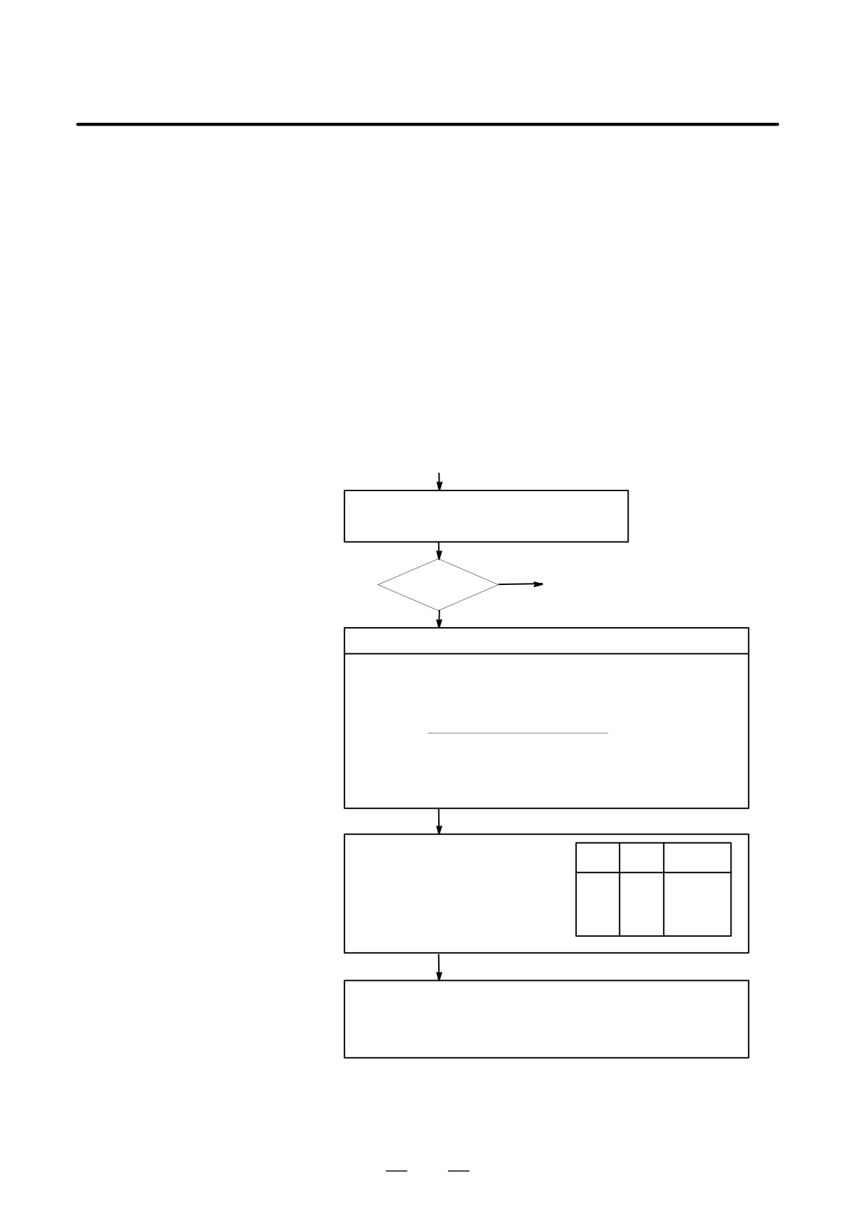
Reference position return was executed when the following condition is
not satisfied:
The CNC received one rotation signal at least one time when the axis is
moving to the reference position at a speed higher than a speed equivalent
to 128 pulses of position error amount(DGN300).
Countermeasures
(START)
Position error
Check whether position gain is greater than 128 pulses
amount : DGN 300
(DGN 300) before or during reference position return.
YES
128 or more
(1) Next page
NO
Raise the speed
Check feed rate command:
PRM 1420 F : Rapid traverse rate
(mm/min)
PRM 1424
Manual rapid traverse rate (mm/min)
PRM 1825 G : Servo loop gain
(0.01sec-1)
F
5000/3
Position error=
G detection unit[µm/PLUSE]
Detection unit : Move amount to a command pulse (usually 1µm)
In metric machine, if the no. of digits below decimal point is 4 on the position
display screen, detection unit is 0.1 µm.
Check rapid traverse override signals :
ROV1
DGN
014.0
ROV1
ROV2
Override
1014.0 (For two-
path control)
0
0
100%
ROV2
DGN
014.1
0
1
50%
1014.1 (For two-
1
0
25%
path control)
1
1
Fo rate
PRM
1421
Fo rate
Check reference position return deceleration signal
DEC1 to DEC8 DGN 009.0 to 009.7
When reference position return is started from deceleration signal 0, feed rate
becomes FL rate.
PRM 1425 FL rate
490
B-64115EN/02
8. TROUBLESHOOTING
(1)
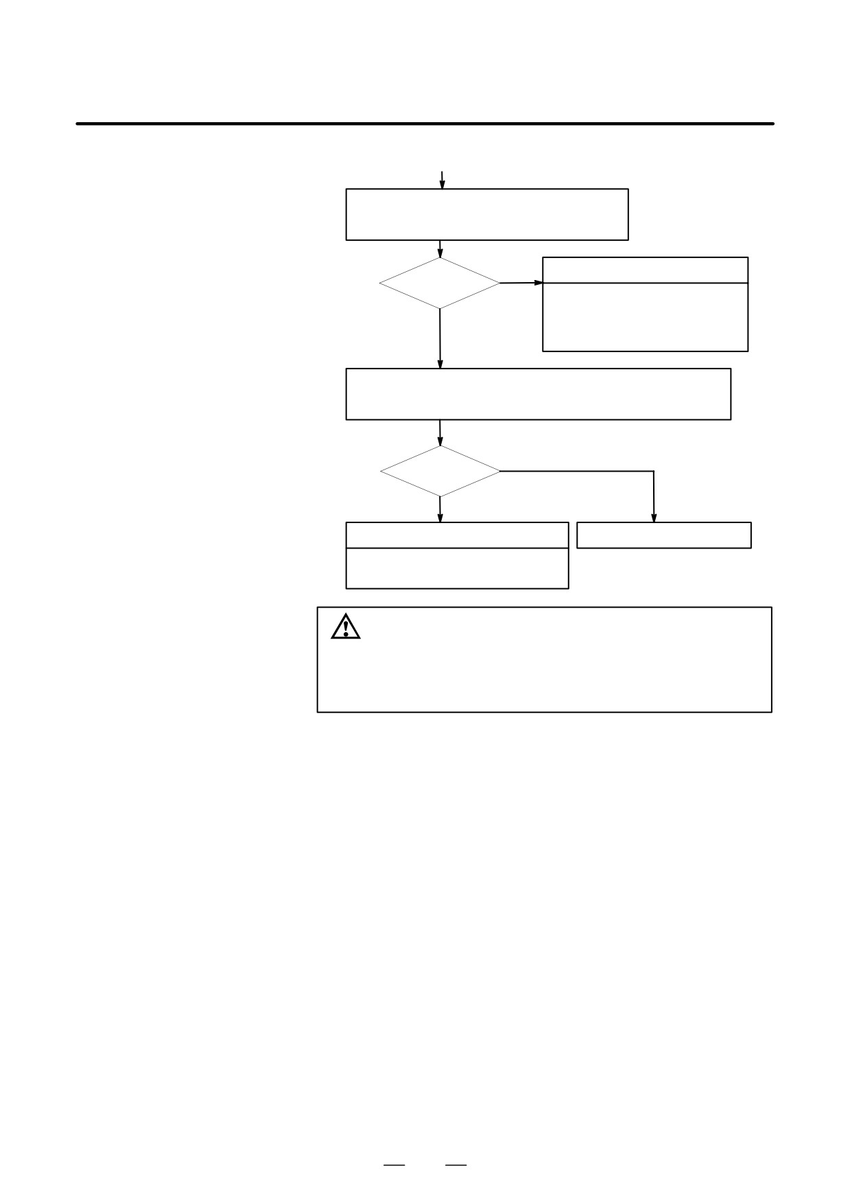
Check whether the motor ratated more than one rota-
tion (one rotation signal is issued ) at faster than 128
pulses of position error amount.
NO
Return start position is too close
Rotated ?
· Chagne the return start position.
· Move the machine at faster that 128
YES
pulses for more than one rotation to
wards RP.
Check that voltage of pulse coder is higher than 4.75 V.
To measure pulse coder voltage, remove the motor cover and measure on
pulse coder PCB at across + and - or +5V and 0V terminals.
NO
More than 4.75V
YES
Hardware failure
Pulse coder power voltage is low
· Pulse coder is faulty
Change pulse coder or motor
CAUTION
After the pulse coder or motor is exchanged, reference
position or machine’s standard point may be different from
former one. Please set it correctly.
D Reference
A speed more than 128 pulses is required because if speed is lower that
this, one-rotation signal does not function stably, causing improper
position detection.
If bit 0 of parameter No. 2000 is set to 1, a speed corresponding to a
positional deviation of 1280 pulses or more is required.
Parameter No. 1836 can be set to 128 or less, as the minimum positional
deviation with which reference position return is possible.
(If the
parameter is set to 0, 128 is assumed as the minimum positional deviation.
If bit 0 of parameter No. 2000 is set to 1, a value equal to ten times the
set value is used for checking.)
491

8. TROUBLESHOOTING
B-64115EN/02
Absolute position data in the serial pulse coder was lost.
8.13
(This alarm will be generated when serial pulse coder is exchanged or
ALARM 300
position feedback signal cable of the serial pulse coder is disconnected).
(REQUEST FOR
REFERENCE
POSITION RETURN)
Remedies
Machine position must be memorized using the following method:
D When reference position
(1) Execute manual reference position return only for an axis for which
return function is
this alarm was generated.When manual reference position return
present
cannot be executed because of an another alarm, set parameter 1815#5
to 0 and release the alarm and perform manual operation.
(2) Press
RESET
key at the end of reference position return to release the
alarm.
D When reference position
Execute dogless reference position setting to memorize the reference
return function is not
position.
present
D When serial pulse coder
Since the reference position is different from the former one, change the
is changed
grid shift value (PRM 1850) to correct the position.
Related parameters
#7
#6
#5
#4
#3
#2
#1
#0
1815
APC x
APZx
#5(APCx)
0 : Position detector is incremental pulse coder.
1 : Position detector is absolute pulse coder.
#4(APZx)
Reference position of absolute pulse coder is :
0 : not established
1 : established
492
B-64115EN/02
8. TROUBLESHOOTING
8.14
ALARM 401
(V READY OFF)
Causes and actions
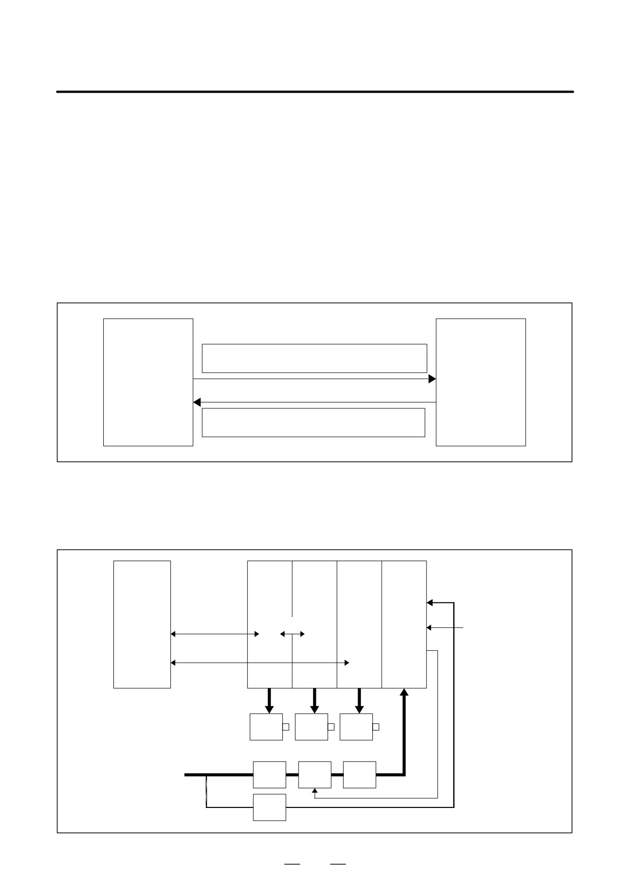
This alarm is issued if the servo ready signal (VRDY) of a servo amplifier
does not turn on or if the signal turns off during operation.
There are cases in which this alarm is issued because another servo alarm
is issued. If this occurs, first take the action for the first alarm.
Check the power magnetic circuit around the amplifier. The servo
amplifier or the axis control cards on the CNC may be defective.
D VRDY
CNC (Main board)
Servo amplifier
MCON: From the CNC to the servo amplifier
(Turn MCC on to request the activation of the servo motor)
VRDY: From the servo amplifier to the CNC
(Notifies that the servo is ready)
The exchange of this information is performed via the FSSB (optical cable).
D Example of connection
around the amplifier
(Typical example)
CNC
SVM
SVM
SPM
PSM
(servo
(servo
amplifier)
amplifier)
Control
power
supply
FSSB
FSSB
ESP
Emergency stop
circuit
MCC
Serial spindle
Servo
Servo
Spindle
motor
motor
motor
3-phase
AC
AC200V
Breaker
MCC
reactor
Single-
phase
Breaker
493
8. TROUBLESHOOTING
B-64115EN/02
Check items
D Is the PSM control power supply on?
D Has an emergency stop been canceled?
D Is a terminating connector connected to the JX1B connector of the
terminating amplifier?
D Is MCC on? If there is an external MCC sequence in addition to the
MCC contact of the PSM, check that sequence also.
D Is the power for driving MCC supplied?
D Is the breaker on?
D Has some alarm been issued in the PSM or SPM?
D Replacing the servo
If no problem is found in the power magnetic circuit around the amplifier,
amplifier
replace the servo amplifier.
D Replacing the axis
If the above action does not solve the problem, replace the axis control
control cards
card.
See Section 2.4, “CONNECTOR AND CARD CONFIGURATIONS OF
PRINTED CIRCUIT BOARDS” for an explanation of the mounting
locations of the cards.
494
B-64115EN/02
8. TROUBLESHOOTING
8.15
ALARM 404
(V READY ON)
Causes and actions
This alarm is issued if the servo ready signal (VRDY) of a servo amplifier
remains on.
The servo amplifier or the axis control cards on the CNC may be
defective.
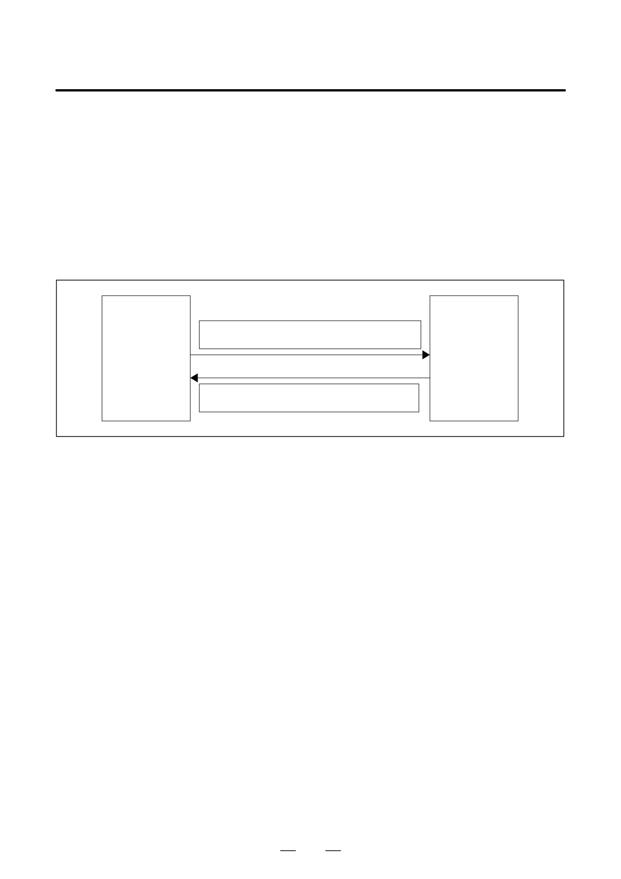
D VRDY
CNC
Servo amplifier
(Main CPU board)
MCON: From the CNC to the servo amplifier
(Turn MCC on to request the activation of the servo motor)
VRDY: From the servo amplifier to the CNC
(Notifies that the servo is ready)
The exchange of this information is performed via the FSSB (optical
cable).
This alarm is issued if VRDY remains on when the CNC turns MCON
off or if VRDY turns on before the CNC turns MCON on.
D Replacing the servo
The servo amplifier may be defective. Replace the servo amplifier.
amplifier
D Replacing the axis
If replacing the servo amplifier does not solve the problem, replace the
control cards
axis control card.
See Section 2.4, “CONNECTOR AND CARD CONFIGURATIONS OF
PRINTED CIRCUIT BOARDS” for an explanation of the mounting
locations of the cards.
495
8. TROUBLESHOOTING
B-64115EN/02
8.16
ALARM 462
(SEND CNC DATA
FAILED)
ALARM 463
(SEND SLAVE DATA
FAILED)
Causes and actions
Alarm 462 is issued if a slave (servo amplifier) cannot receive correct data
due to an FSSB communication error.
Alarm 463 is issued if the CNC cannot receive correct data due to an FSSB
communication error.
If these alarms are issued, the alarm message indicates the number of the
defective axis (axis name).
D Servo amplifier or optical
Any of the optical cables between the CNC control unit and the amplifier
cable
corresponding to the axis number indicated in the alarm message may be
defective.
Or, any of the first amplifier to the amplifier corresponding to that axis
number may be defective.
D Axis control cards
The axis control card installed on the CNC may be defective.
See Section 2.4, “CONNECTOR AND CARD CONFIGURATIONS OF
PRINTED CIRCUIT BOARDS” for an explanation of the mounting
locations of the cards.
496

B-64115EN/02
8. TROUBLESHOOTING
Digital servo parameters are abnormal.
8.17
(Digital servo parameters are set incorrectly.)
ALARM 417 (DIGITAL
SERVO SYSTEM IS
ABNORMAL)
D Causes
1
Confirm the setting value of the following parameters:
PRM 2020 : Motor format number
PRM 2022 : Motor rotation direction
PRM 2023 : Number of pulses of velocity feedbacks
PRM 2024 : Number of pulses of position feedback
PRM 1023 : Servo axis number
PRM 2084 : Flexible feed gear ratio
PRM 2085 : Flexible feed gear ratio
Confirm the details with diagnosis function of CNC side.
2
Change the setting of this parameter to 0.
PRM 2047 : Observer parameter
3
Perform initial setting of digital servo parameters.
Refer to setcion 6.1 “Initial Setting of Servo Parameters” .
This data indicates the cause of servo alarm No. 417, detected by the NC.
If the alarm is detected by the servo, the PRM bit (bit 4 of DGN No. 0203)
is set to 1.
#7
#6
#5
#4
#3
#2
#1
#0
0280
AXS
DIR
PLS
PLC
MOT
#0(MOT) :
The motor type specified in parameter No. 2020 falls outside the
predetermined range.
#2(PLC) :
The number of velocity feedback pulses per motor revolution, specified in
parameter No. 2023, is zero or less. The value is invalid.
#3(PLS) :
The number of position feedback pulses per motor revolution, specified in
parameter No. 2024, is zero or less. The value is invalid.
#4(DIR) :
The wrong direction of rotation for the motor is specified in parameter No.
2022 (the value is other than 111 or -111).
#6(AXS) :
In parameter No. 1023 (servo axis number), a value that falls outside the
range of 1 to the number of controlled axes is specified. (For example, 4 is
specified instead of
3.)
Alternatively, the values specified in the
parameter are not consecutive.
497
8. TROUBLESHOOTING
B-64115EN/02
8.18
ALARM 700
(OVERHEAT:
CONTROL UNIT)
Causes and actions
This alarm is issued if the ambient temperature of the CNC control unit
is abnormally high. As an installation condition, the ambient temperature
of the CNC must not exceed 55°C.
D Ambient temperature
A temperature monitoring circuit is installed on the main board, and
causes this alarm to be issued if the ambient temperature is abnormally
high.
Take appropriate action to the cabinet that houses the CNC control unit
so that the temperature falls within the proper temperature range 0 to
58°C.
If it is obvious that the ambient temperature is not abnormal, the main
board may be defective.
498
B-64115EN/02
8. TROUBLESHOOTING
8.19
ALARM 701
(OVERHEAT: FAN
MOTOR)
Causes and actions
This alarm is issued if a fault occurs in any of the fan motors, such as the
stoppage of a fan motor during the operation of the CNC.
D Fan motors
Fan motors are installed in the uppermost portion of the CNC control unit.
Each fan motor is attached with an alarm detector circuit, which notifies
the CNC of a fault such as the stoppage of the fan motor, thereby issuing
this alarm.
If this alarm is issued, replace the fan motor.
See Section 2.11 for an explanation of the replacement procedure.
499
8. TROUBLESHOOTING
B-64115EN/02
Spindle speed changes abnormally due to load.
8.20
ALARM 704
(SPINDLE SPEED
FLUCTUATION
DETECTION ALARM)
Remedies
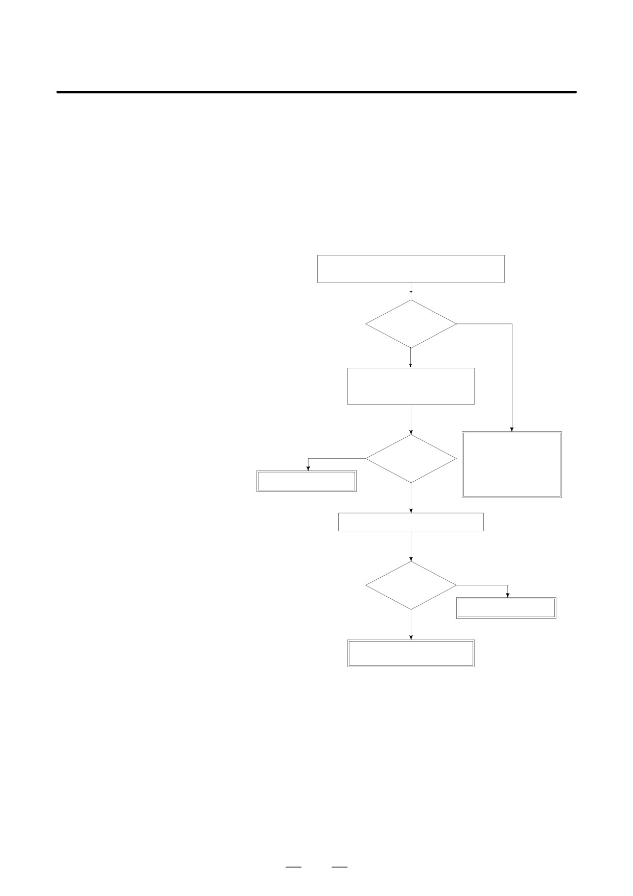
Check whether spindle speed is constant by view
of the speed meter on CRT.
YES
Constant ?
NO
Is a heavy cutting being per-
formed ? Confirm spindle load
on CRT.
Confirm the follow-
ing parameter :
YES
Heavy cutting?
PRM 4911
PRM 4912
Reduce cutting condition
PRM 4913
NO
PRM 4914
Doesn’t the cutting tool worn ?
YES
Worn ?
Replace tool
NO
Spindle servo unit is faulty
Spindle motor is faulty
Remedies
PRM 4911 : A ratio of spindle speed at which actual spindle speed is
regarded as arrived at a command spindle speed.
PRM 4912 : Spindle speed fluctuation ratio up to which the spindle
speed fluctuation detection alarm is not issued.
PRM 4913 : Spindle speed fluctuation that is not regarded as the spindle
speed fluctuation alarm.
PRM 4914 : Time when a spindle speed changed to when spindle speed
fluctuation detection is started.
500

B-64115EN/02
8. TROUBLESHOOTING
8.21
ALARM 749
(SERIAL SPINDLE
COMMUNICATION
ERROR)
Causes and actions
An error occurred in the communication between the serial spindle
amplifier (SPM) and the CNC. The probable causes include:
D Contact failure of the connection cable
D Defective printed circuit board on the CNC
D Defective spindle amplifier
D Noise
D Connection cable
Check that the cable connecting the serial spindle amplifier (SPM) to the
CNC is in contact.
Check that the cable is inserted firmly into the connectors and that it does
not have any conductors likely to be cut off.
Check that the cable used is a twisted-pair cable and that it is connected
as described in the connection manual.
D Printed circuit boards on
A spindle control circuit for the CNC is installed on the main board. If
the CNC
this alarm is issued, replace the main board.
D Spindle amplifier module
When an error occurred on the spindle amplifier module (SPM) side, a
(SPM)
code of A, A1, or A2 is indicated on the SPM depending on the nature of
the error.
In this case, take appropriate actions in the Maintenance Manual of your
servo motor.
D Noise environment
If any of the above actions does not solve the problem, examine the noise
environment of the connection cable.
See the section on the measures against noise, take appropriate actions
such as the reinforcement of the cable shield and the separation of the
cable from the power line.
501
8. TROUBLESHOOTING
B-64115EN/02
8.22
ALARM 750
(SPINDLE SERIAL
LINK STARTUP
FAILURE)
Causes and actions
This alarm is issued if a serial spindle amplifier (SPM) does not enter the
normal startup state when the CNC is turned on.
This alarm is not issued once the CNC system including the spindle
amplifiers has started up normally. It is issued if a fault occurs in the
power-on process.
The probable causes include the following:
D Contact failure, wiring error, or connection error of the connection
cable
D The CNC is turned on when a spindle amplifier is in the alarm state.
D Parameter setting error
D Defective printed circuit board on the CNC
D Detective spindle amplifier
D Connection
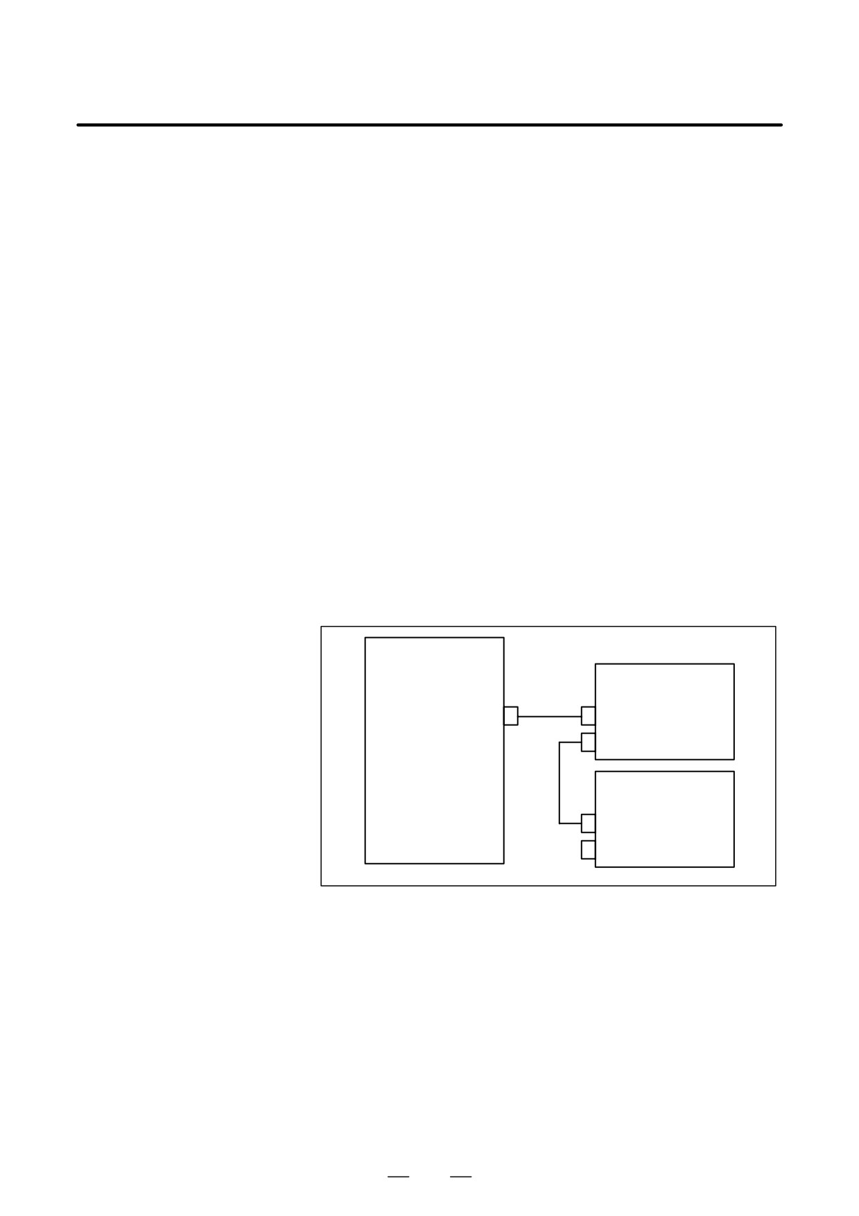
Up to two serial spindle amplifiers (SPMs) can be connected per path.
Note, however, the number of amplifiers that can be connected differs
depending on the model, number of paths, and configuration. Refer to the
Connection Manual (Hardware).
Main board
SPM (first)
JA7A
JA7B
JA7A
SPM (second)
JA7B
JA7A
Check that the cables are connected as shown in the figure above. Check
that JA7Bs and JA7As are connected correctly.
Check that the cables are latched firmly and are not loose.
Refer to the Connection Manual (Hardware) to check that the cables are
connected correctly.
D States of the spindle
This alarm is issued if the CNC is turned on when the LED of a spindle
amplifiers
amplifier indicates a number other than “24”.
On the spindle amplifier, remove the cause of the alarm. Turn off the
spindle amplifier and the CNC, then turn on the system again.
D Details of the alarm
If this alarm is issued, its details can be checked with diagnosis numbers
409 and 439.
502

B-64115EN/02
8. TROUBLESHOOTING
D 1st and 2nd spindles
#7
#6
#5
#4
#3
#2
#1
#0
0409
SPE
S2E
S1E
SHE
SPE:
0 : In the spindle serial control, the serial spindle parameters fulfill the
spindle unit startup conditions.
1 : In the spindle serial control, the serial spindle parameters do not fulfill
the spindle unit startup conditions.
S2E:
0 : The second spindle is normal during the spindle serial control startup.
1 : The second spindle was detected to have a fault during the spindle
serial control startup.
S1E:
0 : The first spindle is normal during the spindle serial control startup.
1 : The first spindle was detected to have a fault during the spindle axis
serial control startup.
SHE:
0 : The serial communications circuit in the CNC is normal.
1 : The serial communications circuit in the CNC was detected to have a
fault.
503

8. TROUBLESHOOTING
B-64115EN/02
8.23
ALARM 5134
(FSSB: OPEN
READY TIME OUT)
ALARM 5135 (FSSB:
ERROR MODE)
ALARM 5137 (FSSB:
CONFIGURATION
ERROR)
ALARM 5197 (FSSB:
OPEN TIME OUT)
ALARM 5198 (FSSB:
ID DATA NOT READ)
Causes and actions
These alarms are issued if any of the axis control cards and the slaves
(such as servo amplifiers) and optical cables connected to the FSSB is
defective.
No.
Message
Description
5134
FSSB: OPEN READY TIME
The FSSB did not become ready to
OUT
open during initialization.
5135
FSSB: ERROR MODE
The FSSB entered an error mode.
5137
FSSB: CONFIGURATION
The FSSB detected a configuration er-
ERROR
ror.
5197
FSSB: OPEN TIME OUT
The FSSB did not open when the CNC
had allowed the FSSB to open.
5198
FSSB: ID DATA NOT READ
The initial ID information for the amplifi-
er cannot be read because of a failure
in the temporary assignment.
D Processing of the FSSB
The processing of the FSSB at power on is as described below:
at power on
1
The CNC initializes the FSSB and the servo.
2
The servo returns the first ready signal.
3
The first ITP interrupt is generated.
4
The CNC waits for the FSSB to become ready to open.
5
The CNC checks that the FSSB did not detect a configuration error.
6
The CNC allows the FSSB to open.
7
The CNC checks that the FSSB has opened.
8
The servo returns the second ready signal.
9
Normal operation
504
B-64115EN/02
8. TROUBLESHOOTING
If the FSSB does not become ready to open in 4, alarm 5134 is issued.
If an error is detected in 5, alarm 5137 is issued.
If the FSSB does not open within a fixed period of time, alarm 5197 is
issued.
If the ready signal is not returned within a fixed period of time, alarm 5198
is issued.
D Checking the parameter
Check that the FSSB-related parameters are set correctly.
settings
D Power supplies of the
Check the power supplies of the servo amplifiers connected to the FSSB.
servo amplifiers
D Replacing the axis
Replace the axis control cards on the CNC.
control cards, optical
Replace the optical cables and servo amplifiers connected to the FSSB,
cables, and servo
one at a time, to identify the defective item.
amplifiers
See Section 2.4, “CONNECTOR AND CARD CONFIGURATIONS OF
PRINTED CIRCUIT BOARDS” for an explanation of the mounting
locations of the cards.
505
8. TROUBLESHOOTING
B-64115EN/02
8.24
ALARM 5136
(FSSB: NUMBER OF
AMPS IS SMALL)
Causes and actions
The number of servo amplifiers recognized by the FSSB is insufficient,
compared with the number of controlled axes.
D FSSB setting screen
If this alarm is issued, display the amplifier setting screen from the FSSB
setting screen. Only the servo amplifiers recognized on the FSSB are
displayed.
D Optical cable or servo
The optical cable that connects together the last recognized amplifier and
amplifier
the next one may be defective.
Or, either of the amplifiers connected together with that optical cable may
be defective. Check the power supplies of the amplifiers.
D Power fault of a servo
This alarm may be issued if a power fault occurs in a servo amplifier. A
amplifier
power fault occurs if the amplifier control power supply voltage drops,
if the +5 V conductor of the pulse coder cable is ground, or for other
reasons.
D Axis control cards
The axis control cards installed on the CNC may be defective.
See Section 2.4, “CONNECTOR AND CARD CONFIGURATIONS OF
PRINTED CIRCUIT BOARDS” for an explanation of the mounting
locations of the cards.
506
B-64115EN/02
8. TROUBLESHOOTING
8.25
ALARM 900
(ROM PARITY)
Causes and actions
A ROM parity error occurred.
The software including the CNC system software, servo software, PMC
management software, and PMC Ladder is stored in the flash memory on
the FROM/SRAM module. It starts execution after being loaded into the
RAM of the DRAM module or servo card at power on.
A ROM parity error occurs if the software stored in the FROM/SRAM
module is destroyed.
D Rewriting the software
On the screen, the series of the software in which a fault was detected is
component
displayed. Rewrite the software using the boot system.
The software stored in the FROM/SRAM module includes a variety of
FANUC software components, as well as those created by the MTB, such
as the PMC Ladder.
D Replacing the
Replace the FROM/SRAM module
FROM/SRAM module
After replacement, all the software that was once stored must be written.
Because the replacement clears the contents of the SRAM memory, the
memory contents must be restored. For this operation, use the boot
system.
D Replacing the main
If any of the above actions does not solve the problem, replace the main
board
board
See Section 2.4, “CONNECTOR AND CARD CONFIGURATIONS OF
PRINTED CIRCUIT BOARDS” for an explanation of the mounting
locations of the cards.
507
8. TROUBLESHOOTING
B-64115EN/02
8.26
ALARMS 912 TO 919
(DRAM PARITY)
Causes and actions
The management software for the CNC is loaded from the FROM to the
DRAM at power on, so that it is executed on the DRAM.
A parity error occurred on this DRAM.
These alarms occur if the data on the DRAM is destroyed due to some
external cause or if the CPU card is defective.
D Replacing the CPU card.
Replace the CPU card.
The DRAM is mounted on the CPU card.
See Section 2.4, “CONNECTOR AND CARD CONFIGURATIONS OF
PRINTED CIRCUIT BOARDS” for an explanation of the mounting
locations of the cards.
NOTE
If the drawing number of the basic unit is A02B-0309-B52n,
A02B-0311-B52n, or A02B-0311-B53n (where n is 0, 1,...,
9), references to the CPU card should be read as the main
board.
508
B-64115EN/02
8. TROUBLESHOOTING
8.27
ALARM 920
(SERVO ALARMS)
Causes and actions
A watchdog error or RAM parity error occurred in the circuit on an axis
control card.
Alarm 920 indicates that either of the above errors occurred in the control
circuit for axes 1 to 4.
The optical cable, axis control cards, CPU card, or motherboard may be
defective.
D Watchdog error
The servo control circuit monitors the operation of the main CPU. If a
fault occurs in the CPU or its peripheral circuit, so that the watchdog timer
is not reset, a watchdog error occurs.
D Replacing the optical
Replace the optical cable. A defective optical cable may cause this
cable
problem.
D Replacing the axis
Replace the axis control cards.
control cards
D Replacing the CPU card
Replace the CPU card.
D Replacing the main
If any of the above actions does not solve the problem, replace the main
board
board.
See Section 2.4, “CONNECTOR AND CARD CONFIGURATIONS OF
PRINTED CIRCUIT BOARDS” for an explanation of the mounting
locations of the cards.
509
8. TROUBLESHOOTING
B-64115EN/02
8.28
ALARM 926
(FSSB ALARM)
Causes and actions
A fault occurred on the FSSB (serial servo bus) that connects servo
amplifiers to the CNC.
This alarm is issued if a fault occurs in any of the axis control cards
making up the FSSB, optical cables, and servo amplifiers.
D Identifying the defective
Use the LEDs on the servo amplifiers.
location
Using the
7-segment LEDs installed on the servo amplifiers, the
defective location can be identified.
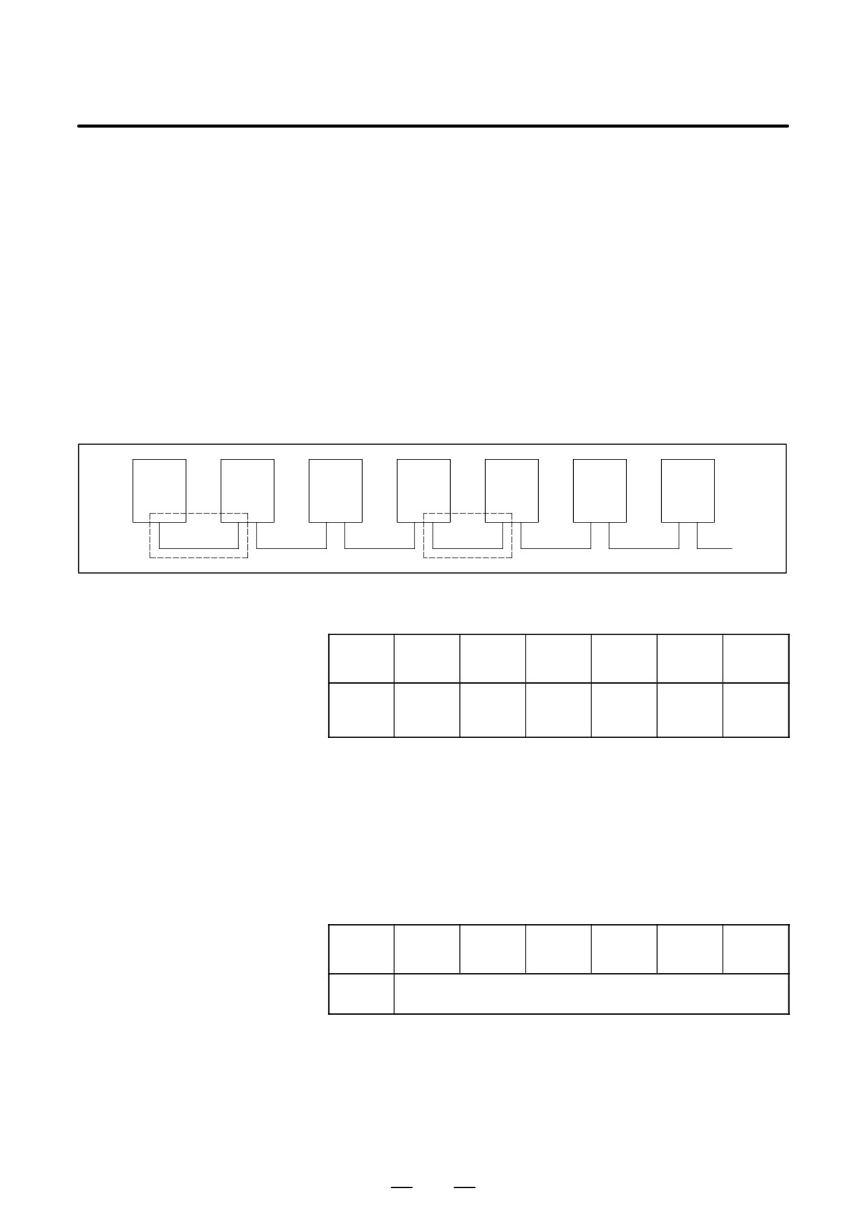
FSSB connection
example
Amplifier
Amplifier
Amplifier
Amplifier
Amplifier
Amplifier
CNC
0
1
2
3
4
5
B
A
If portion A, indicated by dotted line, contains the defective location, the
LEDs on the servo amplifiers will be as shown in the table below.
Amplifier
Amplifier
Amplifier
Amplifier
Amplifier
Amplifier
Amplifier
No.
0
1
2
3
4
5
“L”
LED
“-”
“-”
or
“U”
“U”
“U”
display
“-”
In this case, any of the following locations may be defective:
(1) Optical cable connecting together the servo amplifier whose LED is
“L” or “-” and that whose LED is “U”. In the above figure, the optical
cable in portion A may be defective.
(2) Either of the servo amplifier whose LED is “L” or “-” and that whose
LED is “U”. In the above figure, either amplifier 2 or 3 may be defective.
If portion B, indicated by dotted line, contains the defective location, the
LEDs on the servo amplifiers will be as follows:
Amplifier
Amplifier
Amplifier
Amplifier
Amplifier
Amplifier
Amplifier
No.
0
1
2
3
4
5
LED
“-” or “U”
display
In this case, any of the following locations may be defective:
(1) Optical cable connected to the CNC. In the above figure, the optical
cable in portion B may be defective.
(2) Any of the axis control cards in the CNC
(3) First servo amplifier connected. In the above figure, amplifier 0 may
be defective.
510
B-64115EN/02
8. TROUBLESHOOTING
D Identifying the defective
Use the display on the CNC screen
location
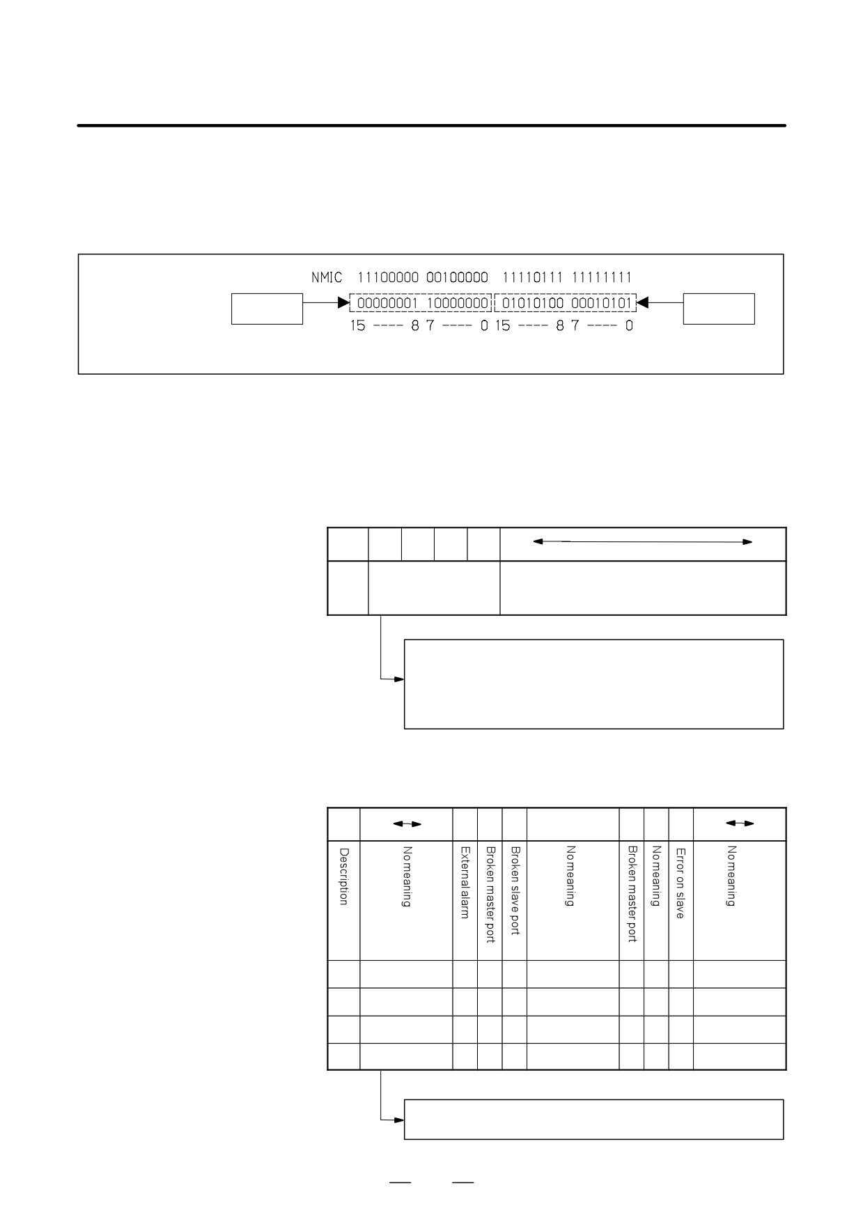
If alarm 926 is issued, information such as the following is displayed at
the bottom of the CNC screen. It can be used to identify the defective
location.
MODE
STATUS
information
information
Bits
Bits
Bits 12 to 15 of the MODE information indicate the number of the slave
in which the alarm occurred. The unit nearest the CNC (such as a servo
amplifier) is assigned a slave number of “0”. For a 2-axis amplifier, for
example, one number is assigned for the first axis, and the next number
is assigned for the second.
Details of the MODE information
Bit
15
14
13
12
11
0
De-
Number of the slave in
No meaning
scrip-
which the alarm oc-
tion
curred
0000: Indicates that the alarm occurred in slave 0.
0001: Indicates that the alarm occurred in slave 1.
:
:
1001: Indicates that the alarm occurred in slave 9.
Using the bits of the STATUS information, the fault can be estimated.
Details of the STATUS information
Bit
15
12
11
10
9
87
6
5
4
3
0
A
xxxx
0
0
0
xxx
1
x
0
xxxx
A
xxxx
0
1
0
xxx
0
x
1
xxxx
B
xxxx
0
0
1
xxx
0
x
1
xxxx
C
xxxx
1
0
0
xxx
0
x
1
xxxx
The STATUS information matches any of the patterns A, B, and C.
(x indicates a bit that may be either 0 or 1.)
511
8. TROUBLESHOOTING
B-64115EN/02
If the pattern of the STATUS information is A
(1) The optical cable that connects together the slave corresponding to bits
12 to 15 of the MODE information and the preceding slave may be
defective. Or, either of the slaves connected together with that optical
cable may be defective.
(2) The voltage of the power supplied to the slave amplifier dropped, or
a power fault occurred in the amplifier.
(3) Any of the axis control cards in the CNC may be defective.
If the pattern of the STATUS information is B
(1) The optical cable that connects together the slave corresponding to bits
12 to 15 of the MODE information and the preceding slave may be
defective. Or, either of the slaves connected together with that optical
cable may be defective.
(2) The voltage of the power supplied to the slave amplifier dropped, or
a power fault occurred in the amplifier.
If the pattern of the STATUS information is C
(1) The slave corresponding to bits 12 to 15 of the MODE information
may be defective.
(2) The voltage of the power supplied to the slave amplifier dropped, or
a power fault occurred in the amplifier.
D Power fault in a servo
If a power fault occurs in a servo amplifier, the FSSB alarm is issued. A
amplifier
power fault occurs, causing the FSSB alarm to be issued, if the amplifier
control power supply voltage drops, if the +5 V conductor of the pulse
coder cable is ground, or for other reasons.
D Replacing the axis
If any of the axis control cards is found defective by the above diagnosis,
control card
replace the axis control card on the main board.
See Section 2.4, “CONNECTOR AND CARD CONFIGURATIONS OF
PRINTED CIRCUIT BOARDS” for an explanation of the mounting
locations of the cards.
512
B-64115EN/02
8. TROUBLESHOOTING
8.29
ALARM 930
(CPU INTERRUPT)
Causes and actions
An interrupt that can never be generated during normal operation was
generated.
The cause of the fault cannot be identified, but the fault may have occurred
in the peripheral circuit of the CPU.
If the problem is solved by turning the power off and then on again, the
problem may be attributable to noise.
D Replacing the CPU card,
Replace the CPU card and the main board.
main board
See Section 2.4, “CONNECTOR AND CARD CONFIGURATIONS OF
PRINTED CIRCUIT BOARDS” for an explanation of the mounting
locations of the cards.
D Examining the noise
See the section on the measures against noise, examine the noise
environment
environment of the CNC.
513
8. TROUBLESHOOTING
B-64115EN/02
8.30
ALARM 935
(SRAM ECC ERROR)
Causes and actions
An ECC error occurred in the SRAM used to store data such as parameters
and machining programs.
This alarm is issued if the battery has run down or if the data in the SRAM
is destroyed due to some external cause. Or, the FROM/SRAM module
or main board may be defective.
D ECC check
This is the method of checking the data stored in the SRAM. It has been
employed instead of the conventional parity check.
With the ECC check method, 8-bit correction data is provided for 16-bit
data, so that if a data error occurs in one of these 16 bits, the error is
automatically corrected with the correction data, allowing the CNC to
continue operation. This alarm is issued if a data error occurs in two or
more bits.
With the conventional parity check method, a system alarm is issued if a
data error occurs even in one bit.
D Checking the battery
The battery is rated 3 V. A battery alarm is issued and “BAT” flashes on
the screen if the voltage of the battery drops to 2.6 V.
If a battery alarm is issued, replace the battery with a new one promptly.
D Performing memory all
Perform a memory all clear operation, then start up the CNC.
clear
Alternatively, if a backup of the data in the SRAM has been made, use the
backup to restore the data. To back up and restore the data in the SRAM,
use the boot system.
D Replacing the
If memory all clear or the restoration of the data with a backup does not
FROM/SRAM module
solve the problem, replace the FROM/SRAM module. Take a backup
copy in advance. All the software must be restored after the replacement.
After replacing the FROM/SRAM module, perform a memory all clear
operation and start up the CNC. All the data must be re-loaded.
If a backup is available, restore the data using the backup, then start up
the CNC.
D Main board
If any of the above actions does not solve the problem, replace the main
board.
See Section 2.4, “CONNECTOR AND CARD CONFIGURATIONS OF
PRINTED CIRCUIT BOARDS” for an explanation of the mounting
locations of the cards.
514
B-64115EN/02
8. TROUBLESHOOTING
8.31
ALARM 950
(PMC SYSTEM
ALARM)
Causes and actions
This alarm is issued if a fault is detected in the PMC.
The probable causes include an I/O link communication error and a
defective PMC control circuit
The I/O Link is a serial interface that connects the CNC to various I/O
D Connecting the I/O Link
devices and allows transfers of I/O signals between devices at high speed.
When multiple devices are connected using the I/O Link, there forms a
relationship that a certain device is a master and the other devices are
slaves. The states of the input signals from the slaves are transferred to
the master at fixed intervals. The output signals from the master are
transferred to the slaves at fixed intervals. In a CNC system, the master
is the CNC (main board).
The I/O signals transferred via the I/O link can be used with the PMC
Ladder.
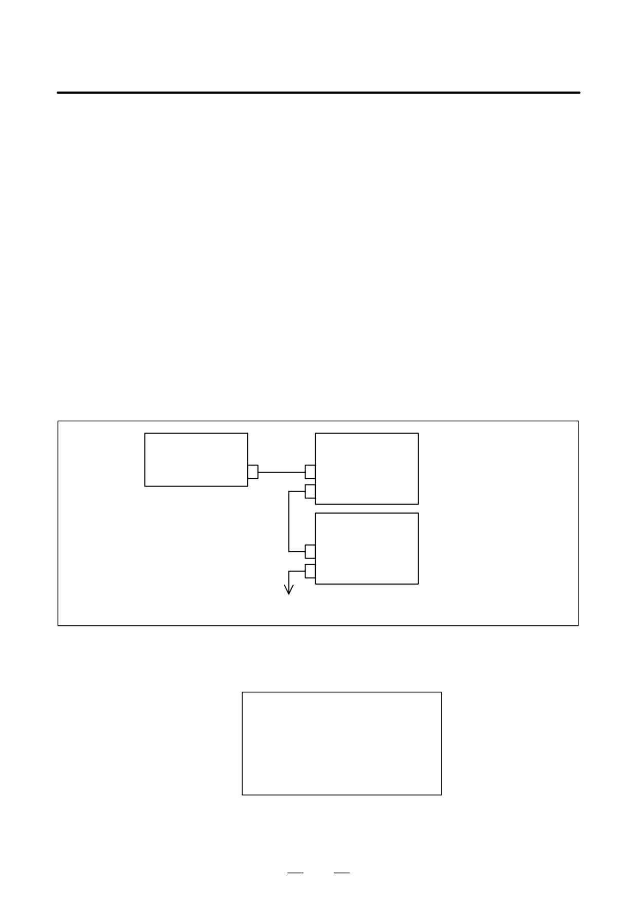
Master station (CNC)
Slave station #0
Group 0
JA1A
JD1B
JD1A
Slave station #1
JD1B
Group 1
JD1A
Up to 16 groups
D I/O Link communication
If alarm 950 is issued, displaying “PC050” on the screen, an I/O link
error PC050
communication error may have occurred.
Screen display example
SYSTEM ALARM
950 PMC SYSTEM ALARM
PC050 I/OLINK(CH1)
xx:yy-aa:bb
or
PC050 I/OLINK(CH2)
aa:bb-xx:yy
or
PC050 IOLINK CH1
aabb-xxyy:aabb
or
PC050 IOLINK CH2
aabb:aabb-xxyy
In this screen display example, the cause of the alarm can be estimated
using xx:yy. xx and yy are hexadecimal representations. CH1 and CH2
are channels on which communication failed.
515
8. TROUBLESHOOTING
B-64115EN/02
1)
If bit 0 of the binary representation of xx is “1”, this indicates that the
master station (CNC) received invalid communication data. For
example, assume that the following is displayed on the screen:
SYSTEM ALARM
950 PMC SYSTEM ALARM
PC050 IOLINK CH1
aabb-4142:aabb
xx is equal to 41, or “01000001” in binary notation. Bit 0, which is
the lowest (rightmost) bit, is “1”.
In this case, check the following:
(1) Noise environment of the I/O Link cable
Noise may disturb the data on the I/O Link and may result in a
problem.
(2) Contact of the I/O Link cable
Check that the I/O link cable is in contact. Check that the cable is
not loose and is latched firmly.
(3) Cable failure
Check that the I/O Link cable is connected properly.
(4) Device failure
The main board or any of the I/O devices connected to the I/O Link
may be defective. Replace the devices, one at a time, to identify
the defective device.
Refer to 2) if bit 1 (second bit from the right) is also “1”.
2)
If bit 1 of the binary representation of xx is “1”, this indicates that an
error was detected on a slave station (I/O device). For example,
assume that the following is displayed on the screen:
SYSTEM ALARM
950 PMC SYSTEM ALARM
PC050 IOLINK CH1
aabb-4382:aabb
xx is equal to 43, or “01000011” in binary notation. Bit 1 (second bit
from the right) is “1”.
In this case, yy indicates the following:
Number equal to the number indicated by bits 0 to 4 of yy minus 1:
Group number of the slave station on which an error was detected
Bit 5 of yy:
Invalid communication data was detected on the slave.
Bit 6 of yy:
Another error was detected on the slave.
Bit 7 of yy:
A watchdog or parity error was detected on the slave.
In the example shown in the figure above, yy is equal to 82, or
“10000010” in binary notation. Bits 0 to 4 are “00010” (2 in decimal
notation). The number “1”, which is equal to that number minus 1, is
the group number of the slave station on which an error was detected.
Bit 7 is “1”. Thus, a watchdog or parity error was detected on the slave
station in group 1.
516

B-64115EN/02
8. TROUBLESHOOTING
In this case, check the following:
(1) If bit 5 of yy is “1”
Perform examination with the same procedure as that in 1).
(2) If bit 6 of yy is “1” or if bit 7 of yy is “1”
First, replace the device of the slave station of the indicated group
number.
If the problem is not solved, perform examination with the same
procedure as that in 1) to identify the defective location.
3)
If bit 2 of the binary representation of xx is “1”, this indicates that the
link between the master station (CNC) and the slave station was
canceled. For example, assume that the following is displayed on the
screen:
SYSTEM ALARM
950 PMC SYSTEM ALARM
PC050 IOLINK CH1
aabb-8400:aabb
xx is equal to 84, or “1000100” in binary notation. Bit 2, which is the
third bit from the right, is “1”.
In this case, check the following:
(1) Disconnection of the slave station from the power supply
Check that the slave station is not turned off, that there are no
instantaneous power failures, and that the capacity of the power
supply is enough.
(2) Disconnection of the I/O link cable
Check that the I/O link cable has not fallen off or has not been
disconnected.
(3) If the problem is not solved, perform a check with the same
procedure as that in 1).
4)
If bit 3 or 4 of the binary representation of xx is “1”, this indicates that
a parity error occurred in the PMC control circuit on the main board.
In this case, replace the motherboard (main board).
D Other cases
The main board may be defective. Replace the main board.
See Section 2.4, “CONNECTOR AND CARD CONFIGURATIONS OF
PRINTED CIRCUIT BOARDS” for an explanation of the mounting
locations of the cards.
517
8. TROUBLESHOOTING
B-64115EN/02
8.32
ALARM 951
(PMC WATCHDOG
ALARM)
Causes and actions
This alarm is issued if a fault (watchdog alarm) is detected in the PMC.
A probable cause is that the MC control circuit is defective.
D Replacing the main
The PMC control circuit is installed on the main board. Replace the main
board
board.
See Section 2.4, “CONNECTOR AND CARD CONFIGURATIONS OF
PRINTED CIRCUIT BOARDS” for an explanation of the mounting
locations of the cards.
518
B-64115EN/02
8. TROUBLESHOOTING
8.33
ALARM 972
(NMI ALARM ON AN
OPTION BOARD)
(Series 0i-C ONLY)
Causes and actions
This alarm indicates that an error was detected on an option board, not on
the main board.
D Screen display
If alarm 972 is issued, the following is displayed on the screen:
Screen display example
SYSTEM ALARM
972 NMI OCCURRED IN OTHER MODULE
SLOT 01
“SLOT” indicates the number of the slot into which the option board is
inserted. Alternatively, it may indicate the number of the alarm that
occurred on the option board. Take the action related to that alarm to the
option board.
D Replacing the option
Replace the option board inserted into the slot with the indicated slot
board
number.
519