FANUC Series 30i-MODEL B, 31i-MODEL B, 32i-MODEL B. MAINTENANCE MANUAL - page 29
B.1
UNITS AND PRINTED CIRCUIT BOARDS FOR
LCD-MOUNTED TYPE CONTROL UNIT
NOTE
Read Section B.4 first for information on units with personal computer functions
with Windows®CE, because some of the printed circuit boards and units used
with them are unique.
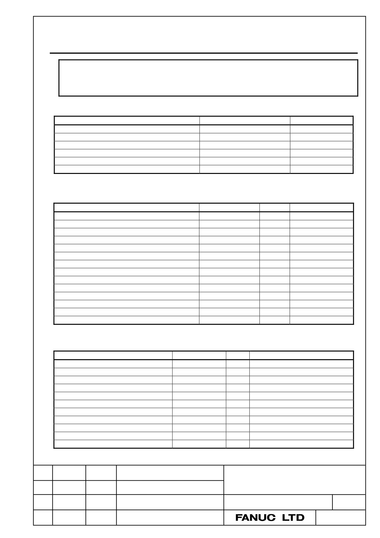
Case
Item
Specification
Remark
Case unit: no slot
A02B-0323-C510
*1
Case unit: 1 slot
A02B-0323-C511
*1
Case unit: 2 slots
A02B-0323-C512
*1
Case for no-slot basic unit
A02B-0323-K090
Case for 1-slot basic unit
A02B-0323-K091
Case for 2-slot basic unit
A02B-0323-K092
*1 The case unit includes the case, fan motor, and battery.
LCD unit
Item
Specification
ID
Remark
8.4”LCD unit
A02B-0323-D503
-
8.4”LCD unit (with protection cover)
A02B-0323-D575
-
10.4"LCD unit A
A02B-0323-D500
-
10.4"LCD unit A (with protection cover)
A02B-0323-D574
-
10.4"LCD unit A (with touch panel)
A02B-0323-D570
-
*2
10.4"LCD unit A (with touch panel and protection cover)
A02B-0323-D572
-
*2
10.4”LCD unit B
A02B-0323-D505
0111
10.4”LCD unit B (with touch panel)
A02B-0323-D507
0111
10.4”LCD unit B (with protection cover)
A02B-0323-D525
0111
10.4”LCD unit B (with touch panel and protection cover)
A02B-0323-D527
0111
15”LCD unit
A02B-0323-D515
0101
15”LCD unit (with touch panel)
A02B-0323-D517
0101
15”LCD unit (with protection cover)
A02B-0323-D535
0101
15”LCD unit (with touch panel and protection cover)
A02B-0323-D537
0101
*2 Used in combination with the touch panel control board A20B-8002-0312.
Printed circuit boards
Item
Specification
ID
Remark
Main board A1
A20B-8200-0720
00338
Main board A2
A20B-8200-0721
00339
Main board A4
A20B-8200-0723
0033B
Main board A5
A20B-8200-0724
0033C
Main board B5
A20B-8200-0718
0034E
Main board B7
A20B-8200-0708
0034C
Main board B5
A20B-8200-0718
0034E
Main board B7
A20B-8200-0708
0034C
Main board B6
A20B-8200-0719
0034F
Main board B8
A20B-8200-0709
0034D
Main board B6
A20B-8200-0719
0034F
TITLE
Addition and correction of
FANUC Series 30i/31i/32i-MODEL B
MAINTENANCE MANUAL
CUST.
DRAW. NO. B-64485EN/01-01
Edit.
DATE
Design
Description
SHEET
4 / 9
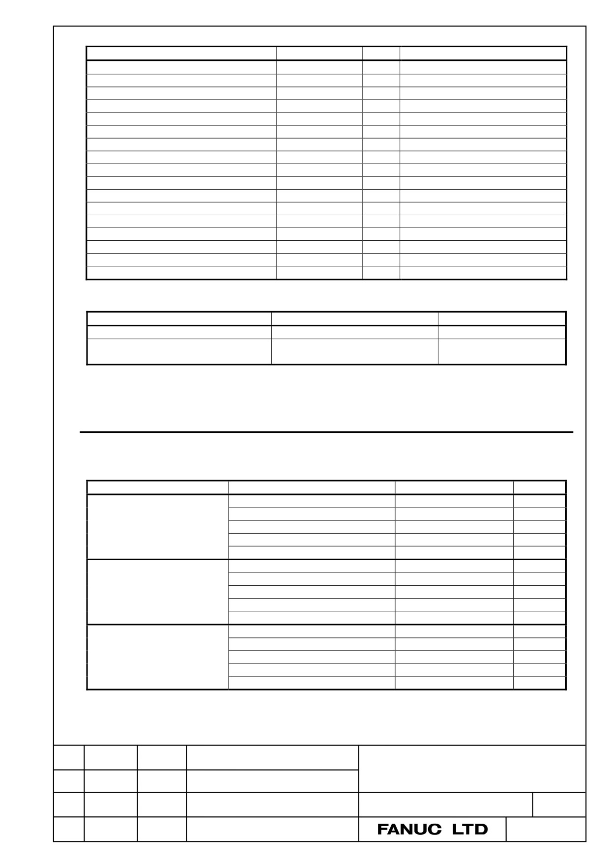
Item
Specification
ID
Remark
Main board B8
A20B-8200-0709
0034D
Main board B1
A20B-8200-0712
00352
Main board B3
A20B-8200-0702
00342
Main board B1
A20B-8200-0712
00352
Main board B3
A20B-8200-0702
00342
Main board B2
A20B-8200-0716
00356
Main board B4
A20B-8200-0706
00346
Main board B2
A20B-8200-0716
00356
Main board B4
A20B-8200-0706
00346
Back panel (no slot, with power supply)
A20B-8200-0650
01
Back panel (1 slot, with power supply)
A20B-8200-0670
00
Back panel (2 slots, with power supply)
A20B-8200-0680
10
Inverter board (for 8.4” LCD unit)
A20B-8200-0663
1011
Inverter board (for 10.4” LCD unit)
A20B-8200-0662
1010
Inverter board (for 15” LCD unit)
A14L-0168-0001
-
Touch panel control board
A20B-8002-0312
-
Fan adapter board (for 15” LCD unit)
A20B-8200-0669
-
Others
Item
Specification
Remark
Compact flash card
A02B-0323-C990#A
Connection cable between main board and
A660-4042-T076#L75R00
For 15” LCD unit
inverter board
B.4.2
Personal computer function with Windows® CE for
Stand-alone type Control Unit
Display unit
・ Display unit with 10.4” LCD unit
Item
Name
Specification
Remark
Display unit
Display control board
A20B-8200-0740
A13B-0201-B001
Power supply unit
A20B-8101-0011
Inverter board
A20B-8200-0662
10.4”LCD unit
A02B-0323-D540
ID=1111
Case
A02B-0323-K090
Display unit
Display control board
A20B-8200-0740
(with touch panel)
Power supply unit
A20B-8101-0011
A13B-0201-B003
Inverter board
A20B-8200-0662
10.4”LCD unit (with touch panel)
A02B-0323-D542
ID=1111
Case
A02B-0323-K090
Display unit
Display control board
A20B-8200-0740
(with protection cover)
Power supply unit
A20B-8101-0011
A13B-0201-B004
Inverter board
A20B-8200-0662
10.4”LCD unit (with protection cover)
A02B-0323-D550
ID=1111
Case
A02B-0323-K090
TITLE
Addition and correction of
FANUC Series 30i/31i/32i-MODEL B
MAINTENANCE MANUAL
CUST.
DRAW. NO. B-64485EN/01-01
Edit.
DATE
Design
Description
SHEET
5 / 9
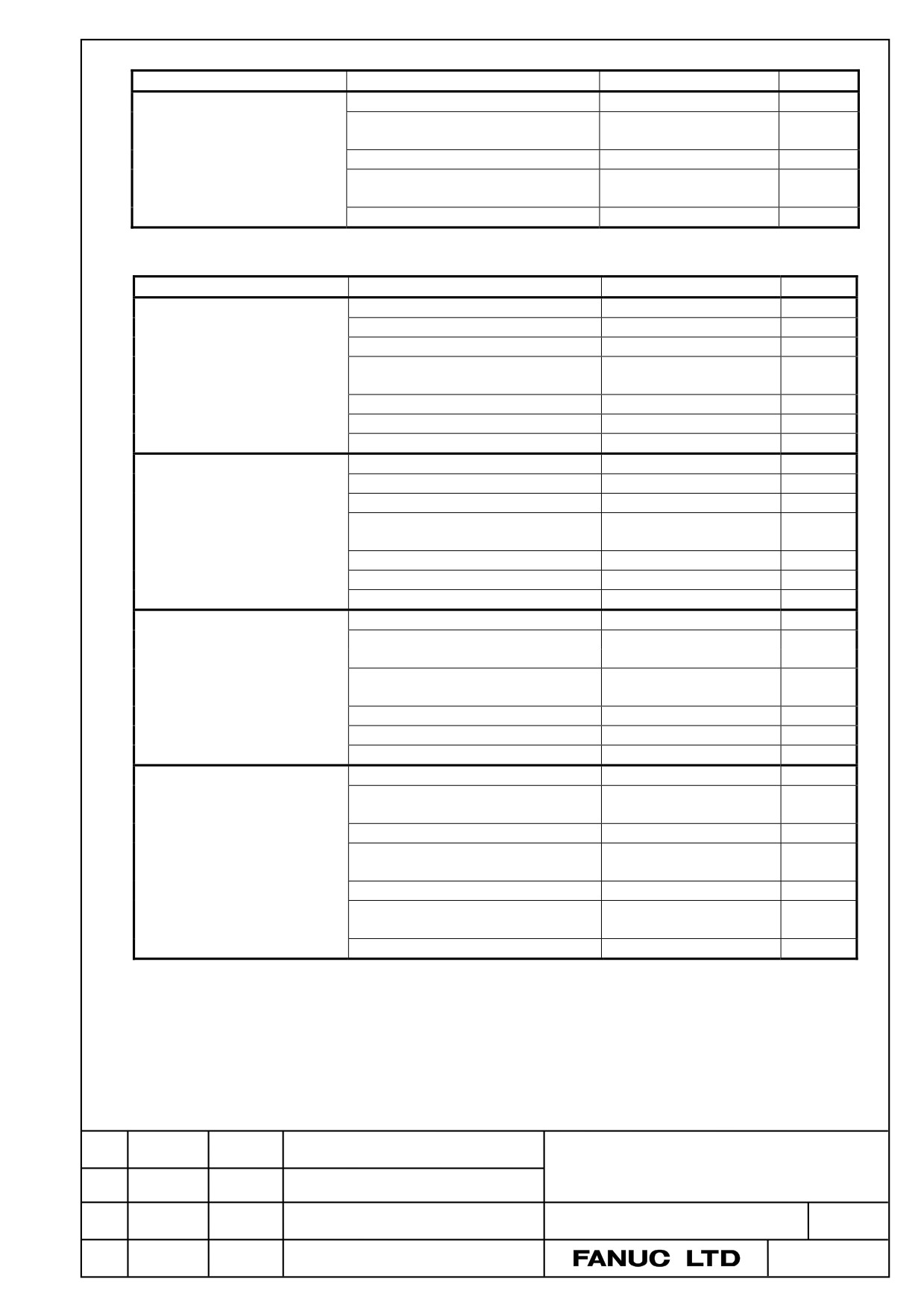
Item
Name
Specification
Remark
Display unit
Display control board
A20B-8200-0740
(with touch panel and protection
Power supply unit
A20B-8101-0011
cover)
A13B-0201-B006
Inverter board
A20B-8200-0662
10.4”LCD unit
A02B-0323-D552
ID=1111
(with touch panel and protection cover)
Case
A02B-0323-K090
・ Display unit with 12.1” LCD unit
Item
Name
Specification
Remark
Display unit
Display control board
A20B-8200-0743
A13B-0201-B011
Power supply unit
A20B-8101-0011
Inverter board
A14L-0143-0003
Connection cable between display
A660-4042-T075#L90R00
control board and inverter board
Fan adapter board
A20B-8200-0669
12.1”LCD unit
A02B-0323-D543
ID=1110
Case
A02B-0323-K090
Display unit
Display control board
A20B-8200-0743
(with touch panel)
Power supply unit
A20B-8101-0011
A13B-0201-B013
Inverter board
A14L-0143-0003
Connection cable between display
A660-4042-T075#L90R00
control board and inverter board
Fan adapter board
A20B-8200-0669
12.1”LCD unit (with touch panel)
A02B-0323-D545
ID=1110
Case
A02B-0323-K090
Display unit
Display control board
A20B-8200-0743
(with protection cover)
Power supply unit
A20B-8101-0011
A13B-0201-B014
Inverter board
A14L-0143-0003
Connection cable between display
A660-4042-T075#L90R00
control board and inverter board
Fan adapter board
A20B-8200-0669
12.1”LCD unit (with protection cover)
A02B-0323-D553
ID=1110
Case
A02B-0323-K090
Display unit
Display control board
A20B-8200-0743
(with touch panel and protection
Power supply unit
A20B-8101-0011
cover)
A13B-0201-B016
Inverter board
A14L-0143-0003
Connection cable between display
A660-4042-T075#L90R00
control board and inverter board
Fan adapter board
A20B-8200-0669
12.1”LCD unit
A02B-0323-D555
ID=1110
(with touch panel and protection cover)
Case
A02B-0323-K090
TITLE
Addition and correction of
FANUC Series 30i/31i/32i-MODEL B
MAINTENANCE MANUAL
CUST.
DRAW. NO. B-64485EN/01-01
Edit.
DATE
Design
Description
SHEET
6 / 9
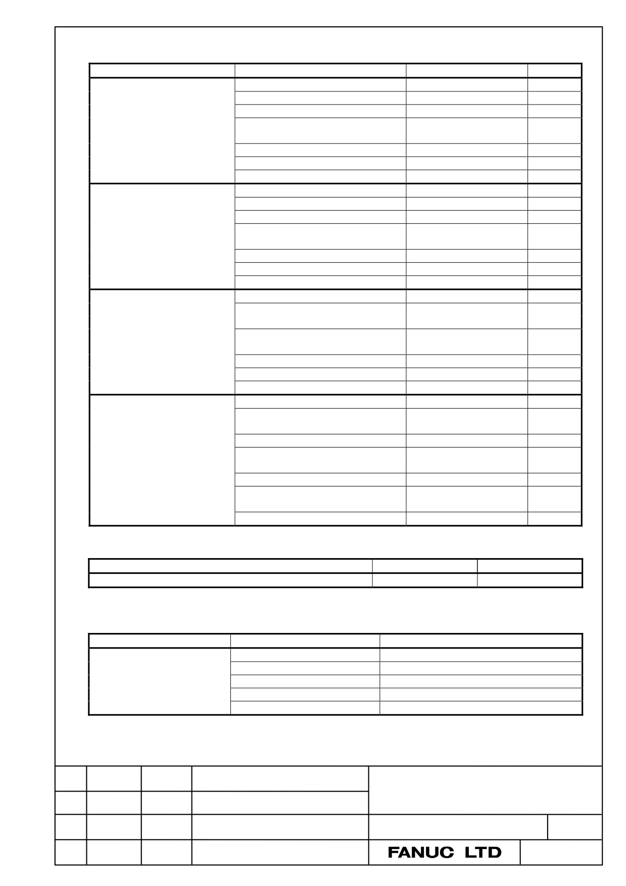
・ Display unit with 15” LCD unit
Item
Name
Specification
Remark
Display unit
Display control board
A20B-8200-0741
A13B-0201-B021
Power supply unit
A20B-8101-0011
Inverter board
A14L-0168-0001
Connection cable between display
A660-4042-T076#L75R00
control board and inverter board
Fan adapter board
A20B-8200-0669
15”LCD unit
A02B-0323-D546
ID=1101
Case
A02B-0323-K090
Display unit
Display control board
A20B-8200-0741
(with touch panel)
Power supply unit
A20B-8101-0011
A13B-0201-B023
Inverter board
A14L-0168-0001
Connection cable between display
A660-4042-T076#L75R00
control board and inverter board
Fan adapter board
A20B-8200-0669
15”LCD unit (with touch panel)
A02B-0323-D548
ID=1101
Case
A02B-0323-K090
Display unit
Display control board
A20B-8200-0741
(with protection cover)
Power supply unit
A20B-8101-0011
A13B-0201-B024
Inverter board
A14L-0168-0001
Connection cable between display
A660-4042-T076#L75R00
control board and inverter board
Fan adapter board
A20B-8200-0669
15”LCD unit (with protection cover)
A02B-0323-D556
ID=1101
Case
A02B-0323-K090
Display unit
Display control board
A20B-8200-0741
(with touch panel and protection
Power supply unit
A20B-8101-0011
cover)
A13B-0201-B026
Inverter board
A14L-0168-0001
Connection cable between display
A660-4042-T076#L75R00
control board and inverter board
Fan adapter board
A20B-8200-0669
15”LCD unit
A02B-0323-D558
ID=1101
(with touch panel and protection cover)
Case
A02B-0323-K090
GUI card
Item
Specification
Remark
GUI card (DDR SDRAM 256MB)
A20B-3300-0671
ID=1111
* See Section B.3 for descriptions of the GUI card (DDR SDRAM 128MB).
Compact flash cards on printed circuit boards
Item
Specification
Remark
Compact flash card
A87L-0001-0173#128MBD
Total capacity: 128MB
A87L-0001-0173#256MBD
Total capacity: 256MB
A87L-0001-0173#512MBD
Total capacity: 512MB
A87L-0001-0173#001GBD
Total capacity: 1GB
A87L-0001-0173#002GBD
Total capacity: 2GB
TITLE
Addition and correction of
FANUC Series 30i/31i/32i-MODEL B
MAINTENANCE MANUAL
CUST.
DRAW. NO. B-64485EN/01-01
Edit.
DATE
Design
Description
SHEET
7 / 9
Backup unit
Item
Specification
Remark
Backup unit
A02B-0303-H160
For installation on the rear of the MDI unit
A02B-0303-C161
For installation inside a cabinet.
A02B-0303-H164
For installation on the rear of the MDI unit (QWRTY TYPE B)
Cable for backup unit
A02B-0323-K801
B.6
OTHER UNITS
Item
Specification
Remark
I/O module for connector panel
A03B-0824-C001
DI/DO : 24/16
(basic module)
I/O module for connector panel
DI/DO : 24/16
A03B-0824-C002
(extension module A)
With manual pulse generator interface
I/O module for connector panel
DI/DO : 24/16
A03B-0824-C003
(extension module B)
Without manual pulse generator interface
I/O module for connector panel
DO : 16
A03B-0824-C004
(extension module C)
2A output module
I/O module for connector panel
A03B-0824-C005
Analog input module
(extension module D)
Cable length: 20mm
Flat cable between modules for I/O module for
A03B-0815-K100
Applicable to an inter-module distance of
connector panel
32 mm
I/O module for operator’s panel
A03B-0824-K200
I/O module for operator’s panel
DI/DO : 48/32
A03B-0824-K202
(with MPG interface)
With manual pulse generator interface
I/O module for power magnetics cabinet
DI/DO : 48/32
A03B-0824-K203
(without MPG interface)
Without manual pulse generator interface
I/O module type-2 for connector panel
A03B-0824-C040
DI/DO : 48/32
(basic module B1)
With manual pulse generator interface
I/O module type-2 for connector panel
A03B-0824-C041
DI/DO : 48/32
(basic module B2)
Without manual pulse generator interface
I/O module type-2 for connector panel
A03B-0824-C042
DI/DO : 48/32
(extension module E1)
Flat cable between modules for I/O module type-2 forA03B-0815-K102
Cable length: 35mm
connector panel
Inter-module distance: 5mm
Terminal type I/O module
DI/DO : 24/16
A03B-0823-C011
Basic module
Terminal type I/O module
DI/DO : 24/16
A03B-0823-C012
Extension module A
With manual pulse generator interface
Terminal type I/O module
DI/DO : 24/16
A03B-0823-C013
Extension module B
Without manual pulse generator interface
Terminal type I/O module
DO : 16
A03B-0823-C014
Extension module C
2A output module
Terminal type I/O module
A03B-0823-C015
Analog input module
Extension module D
Terminal type I/O module
A03B-0823-C016
Analog output module
Extension module E
Spare terminals set
A03B-0823-K020
Terminal block for cable side
(for basic and extension module A/B)
(With one piece of each of T1 to T4
included)
TITLE
Addition and correction of
FANUC Series 30i/31i/32i-MODEL B
MAINTENANCE MANUAL
CUST.
DRAW. NO. B-64485EN/01-01
Edit.
DATE
Design
Description
SHEET
8 / 9
Item
Specification
Remark
Spare terminals set
A03B-0823-K011
Terminal block for cable side for extension
(for extension module C)
module C (With one piece of each of T1
and T2 included)
Spare terminals set
A03B-0823-K012
Terminal block for cable side for extension
(for extension module D)
module D (With one piece of each of T1
and T2 included)
Spare terminals set
A03B-0823-K013
Terminal block for cable side for extension
(for extension module E)
module E (With one piece of each of T1
and T2 included)
Flat cable A between modules for terminal type I/O
A03B-0823-K100
Cable length: 100mm, 52 pins
module
Used to connect an extension module
I/O Link connection unit
A02B-0333-C250
Machine operator's panel: Main panel
A02B-0323-C231
Machine operator's panel: Sub panel A
A02B-0236-C232
Machine operator's panel: Sub panel D
A02B-0236-C244
Operator's panel connection unit (source DO)
A16B-2204-0260
DI/DO : 96/64
Operator's panel connection unit (source DO)
A16B-2204-0261
DI/DO : 64/32
FANUC I/O Link-AS-i converter
A03B-0817-C001
(for AS-i Ver.2.0)
FANUC I/O Link-AS-i converter
A03B-0817-C002
(for AS-i Ver.2.1)
I/O Link signal divider (2ch)
A20B-1007-0680
I/O Link signal divider (3ch)
A20B-1008-0360
Separate detector interface unit (basic 4 axes)
A02B-0323-C205
Separate detector interface unit (additional 4 axes)
A02B-0323-C204
Analog input separate detector interface unit (basic
A06B-6061-C202
4 axes)
Optical I/O Link adapter
A13B-0154-B001
Optical I/O Link adapter (high-speed type)
A13B-0154-B004
Optical junction adapter for I/O Link
A63L-0020-0002
Low-loss optical junction adapter
A63L-0020-0004
Battery case installed outside for control (for
A02B-0236-C282
LCD-mounted type control unit)
Cable for battery case installed outside for control
A02B-0323-K103
(for LCD-mounted type control unit)
Battery case installed outside for control (for
A02B-0236-C281
With cable for battery
stand-alone type control unit)
Compact flash card (128MB)
A02B-0281-K601
For data backup
For Date Server
Compact flash card (256MB)
A02B-0213-K211
For data backup
For Date Server
Compact flash card (1GB)
A02B-0213-K212
For data backup
For Date Server
Compact flash card (2GB)
A02B-0213-K213
For data backup
For Date Server
Compact flash card (4GB)
A02B-0213-K214
For Date Server
Compact flash card adapter A
A02B-0303-K150
Compact flash card adapter B
A02B-0236-K150
Adapter which converts the compact flash
card to the ATA card.
PC-side HSSB interface board (2CH.) Compatible
A20B-8101-0162
with the PCI bus
PC-side HSSB interface board (1CH.) Compatible
A20B-8101-0163
with the PCI bus
TITLE
Addition and correction of
FANUC Series 30i/31i/32i-MODEL B
MAINTENANCE MANUAL
CUST.
DRAW. NO. B-64485EN/01-01
Edit.
DATE
Design
Description
SHEET
9 / 9
Series30i/31i/32i-MODEL B
The correction of maintenance manual
1.Type of applied technical documents
Series30i/31i/32i-MODEL B
Name
MAINTENANCE MANUAL
Spec No./Version
B-64485EN/01
2.Summary of change
New, Add,
Applicable
Group
Name / Outline
Correct,
Date
Delete
Basic Function
Optional Function
Unit
Maintenance parts
Notice
FROM/SRAM module/
Correction
Correct
Immediately
The specification is corrected.
Connector for buzzer interface/
The connector number is changed.
Another
Correct
Immediately
Compact flash card/
The detaching method is changed.
3.List of modifications
Page
Description
Remark
Section 2.3.1, 2.3.2
Connector for buzzer
164, 170
Correction of connection diagram
interface
Section 2.4.2
182
Correction of table in “FROM/SRAM module and
FROM/SRAM module
compact flash card mounting location”
189, 190
Section 2.4.3, 2.5.3
Connector for buzzer
220, 221
Correction of “Connector mounting location”
interface
262, 263
Correction of section 3.7
Compact flash card
※ The page shows a pertinent page of B-64485EN/01.
Title
Series30i/31i/32i-MODEL B
The correction of maintenance manual
DRAW. NO.
CUST
01
11.04.08
Terashima
First issue.
B-64485EN/01-02
SHEET
EDIT
DATE
DESIG.
DESCRIPTION
1 / 9
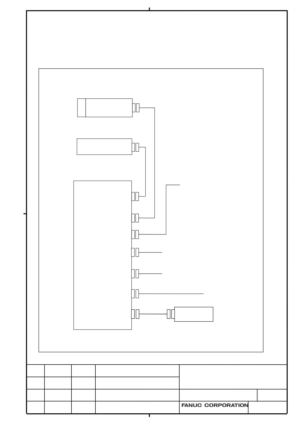
Section 2.3.1
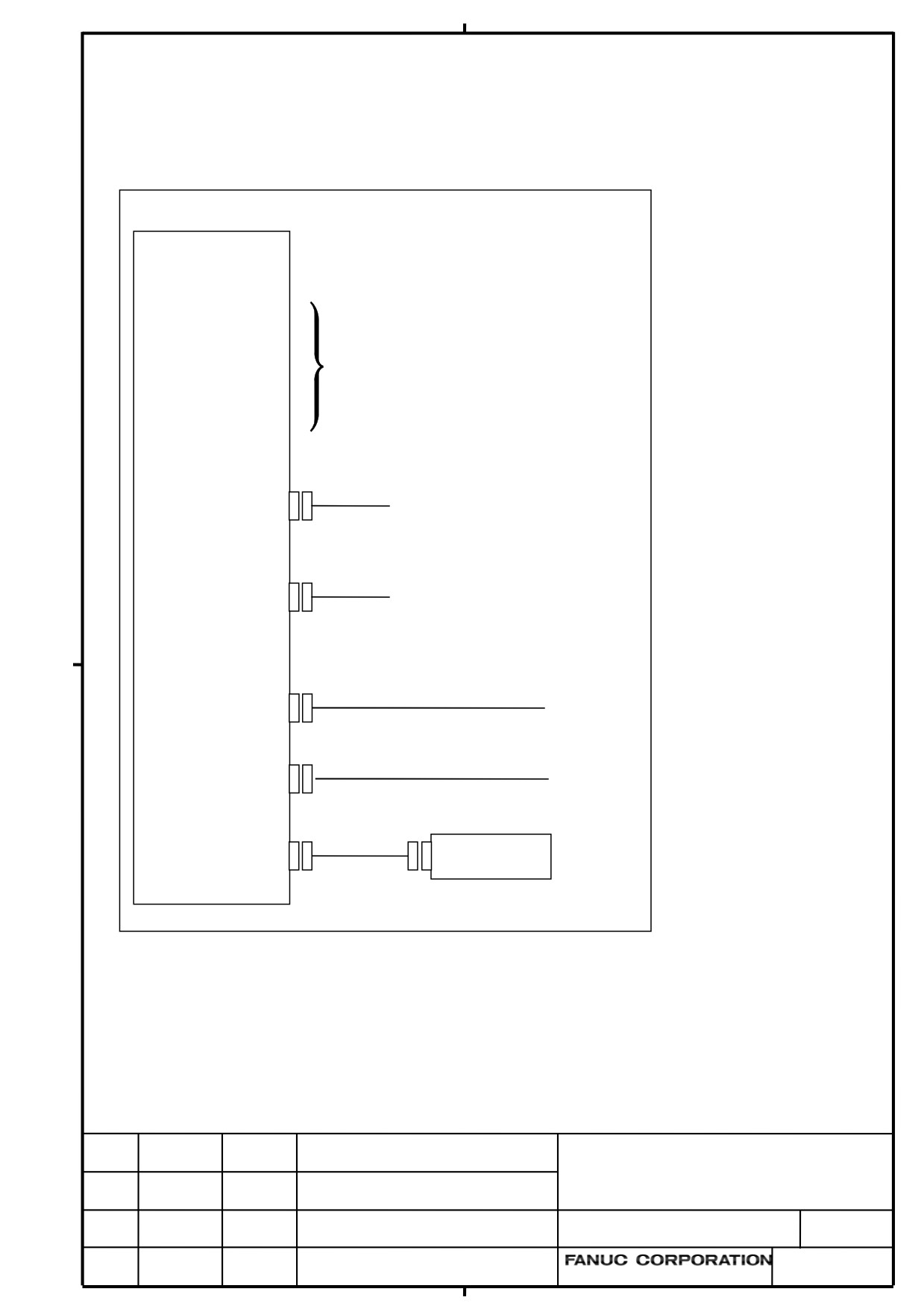
The name of connector for buzzer was corrected.
2.3.1
Control Unit Connection Diagram
LCD-mounted type control unit (personal computer function with Windows® CE)
LCD-mounted type
control unit
24V-IN(CPD16A)
I/O LINK(JD51A)
See the descriptions on the previous
HDI(JA40)
page for the functions of the
connectors listed on the left and how
MDI(CA55)
to attach them.
FSSB(COP10A-1)
FSSB(COP10A-2)
RS232-1(JD56A)
RS-232C I/O device
RS-232C I/O device
RS232-2/USB(JD54)
Personal computer
{
USB keyboard
Ethernet (embedded Ethernet)
ETHERNET (CD38S)
Ethernet (multi-function Ethernet)
ETHERNET (CD38B)
BUZZER for T.P.
Buzzer
(CA149)
Title
Series30i/31i/32i-MODEL B
The correction of maintenance manual
DRAW. NO.
CUST
B-64485EN/01-02
SHEET
EDIT
DATE
DESIG.
DESCRIPTION
2 / 9
Section 2.3.2 The name of connector for buzzer was corrected.
2.3.2
Connection Diagram of a Display Unit for the Stand-Alone
Type Control Unit
Stand-alone type control unit (personal computer function with Windows® CE)
Control unit
Main board
HSSB(COP21A)
MDI unit
(CK27)
Display unit
Power supply (+24VDC)
MDI(CA55)
HSSB(COP21M)
24V-IN(CPD18)
RS-232C I/O device
Personal computer
RS232-2/USB(JD54)
USB keyboard
{
USB printer
RS232-1(JD36)
RS-232C I/O device
Ethernet (embedded Ethernet)
ETHERNET(CD38S)
BUZZER for T.P.
Buzzer
(CA149)
Title
Series30i/31i/32i-MODEL B
The correction of maintenance manual
DRAW. NO.
CUST
B-64485EN/01-02
SHEET
EDIT
DATE
DESIG.
DESCRIPTION
3 / 9
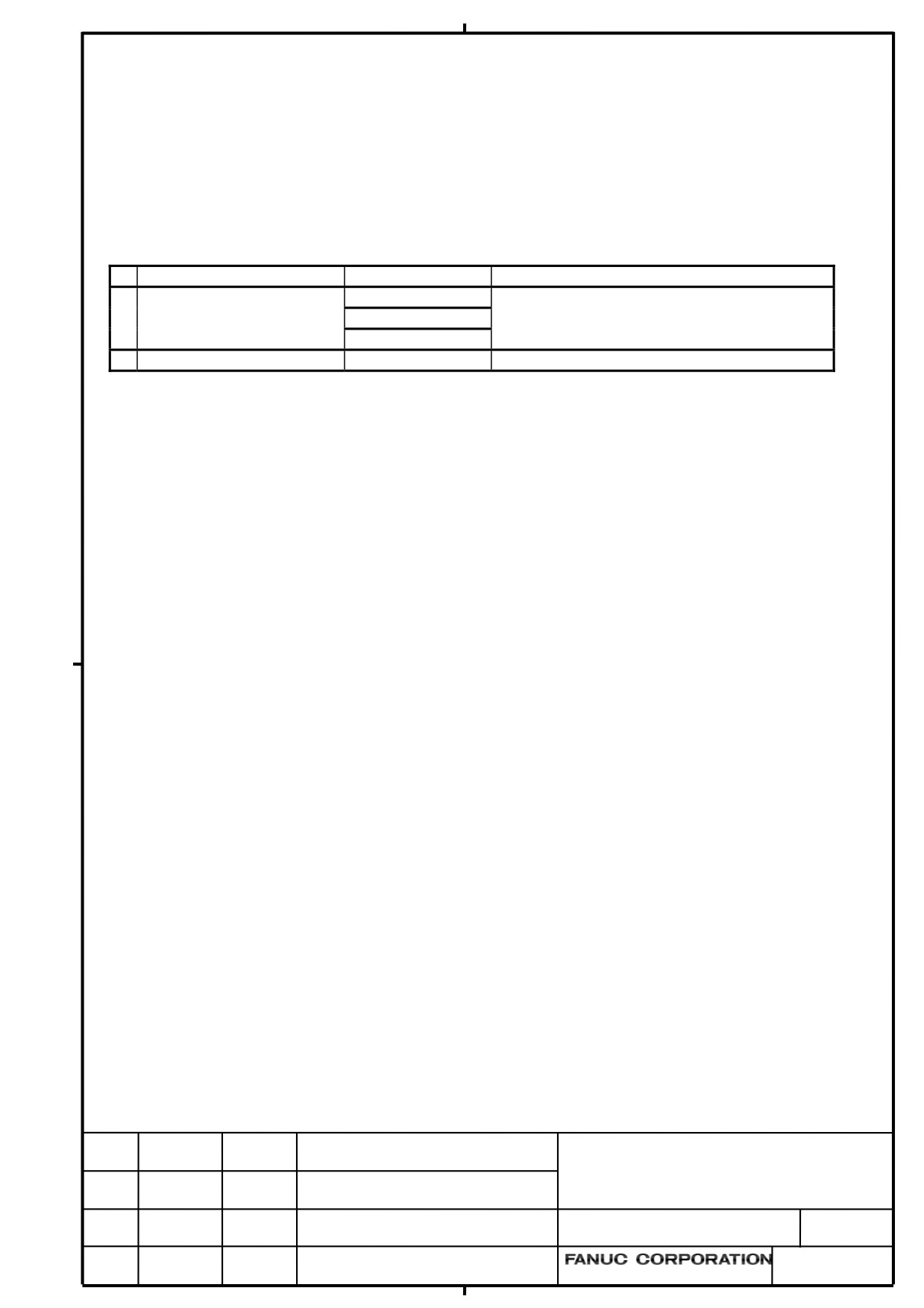
Section 2.4.2 The specification of FROM/SRAM module was corrected.
2.4.2
LCD-mounted Type Control Unit(10.4” LCD Unit B and 15”
LCD Unit)
z
FROM/SRAM module and compact flash card mounting location
No.
Name
Specification
Remark
(1)
FROM/SRAM module
A20B-3900-0250
The FROM stores various control software programs,
A20B-3900-0251
user software programs, and so forth.
The SRAM is a battery-backed memory module.
A20B-3900-0252
(2)
Compact flash card
A02B-0323-C990#A
Including software
Title
Series30i/31i/32i-MODEL B
The correction of maintenance manual
DRAW. NO.
CUST
B-64485EN/01-02
SHEET
EDIT
DATE
DESIG.
DESCRIPTION
4 / 9
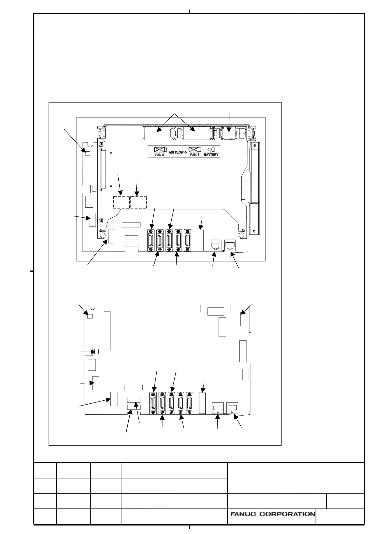
Section 2.4.3 The name of connector for buzzer was corrected.
2.4.3
LCD-mounted Type Control Unit (with Personal Computer
Function with Windows®CE) Hardware
z
Connector mounting location
Fan motor
Battery
CA149
(COP10A is a connector installed on the servo card.)
COP10A-1
COP10A-2
Rear
JD56A JA40
Fuse
CA136
CA55
CPD16A
JD54 JD51A
CD38S
CD38B
CA149
CA135
CA132
JGM
CA133
CA139
CA88A
Main board
CA134
JD56A JA40
CD46L
CA136
Fuse
CA55
CPD16A
CK20A
JD54 JD51A
CD38S
CD38B
CK21A
Title
Series30i/31i/32i-MODEL B
The correction of maintenance manual
DRAW. NO.
CUST
B-64485EN/01-02
SHEET
EDIT
DATE
DESIG.
DESCRIPTION
5 / 9
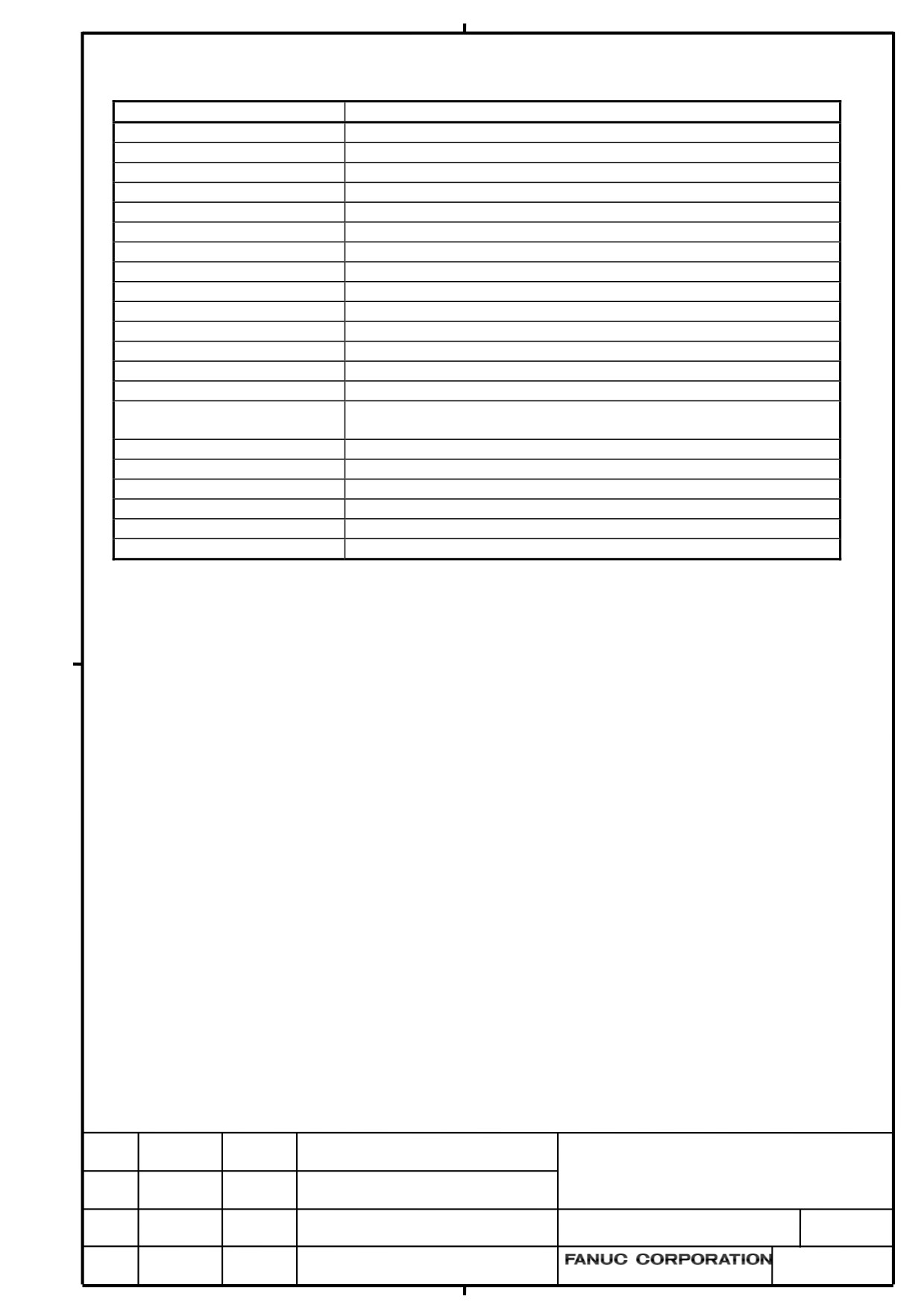
Connector number
Application
COP10A-1, COP10A-2
For FSSB interface
CA55
For MDI
JD56A
For I/O device interface (RS-232C)
JD54
For I/O device interface (RS-232C) or USB device
JA40
For high-speed skip
JD51A
For I/O Link i and I/O Link
CPD16A
For power supply
JGM
For back panel
CA133
For video signal interface (for 10.4”/12.1”LCD)
CA135
For video signal interface (for 15”LCD)
CA88A
For memory card interface
CD46L
For USB port
CK20A
For horizontal soft key
CK21A
For vertical soft key
CA132
For inverter board (for 10.4”LCD)
For fan adapter board (for 12.1”/15” LCD)
CD38S
For Ethernet (Windows CE control or Embedded Ethernet)
CD38B
Ethernet (Multi-function Ethernet)
CA139
For touch panel interface
CA134
For inverter board (for 12.1”/15” LCD)
CA149
For buzzer interface
CA136
For backup unit
Title
Series30i/31i/32i-MODEL B
The correction of maintenance manual
DRAW. NO.
CUST
B-64485EN/01-02
SHEET
EDIT
DATE
DESIG.
DESCRIPTION
6 / 9
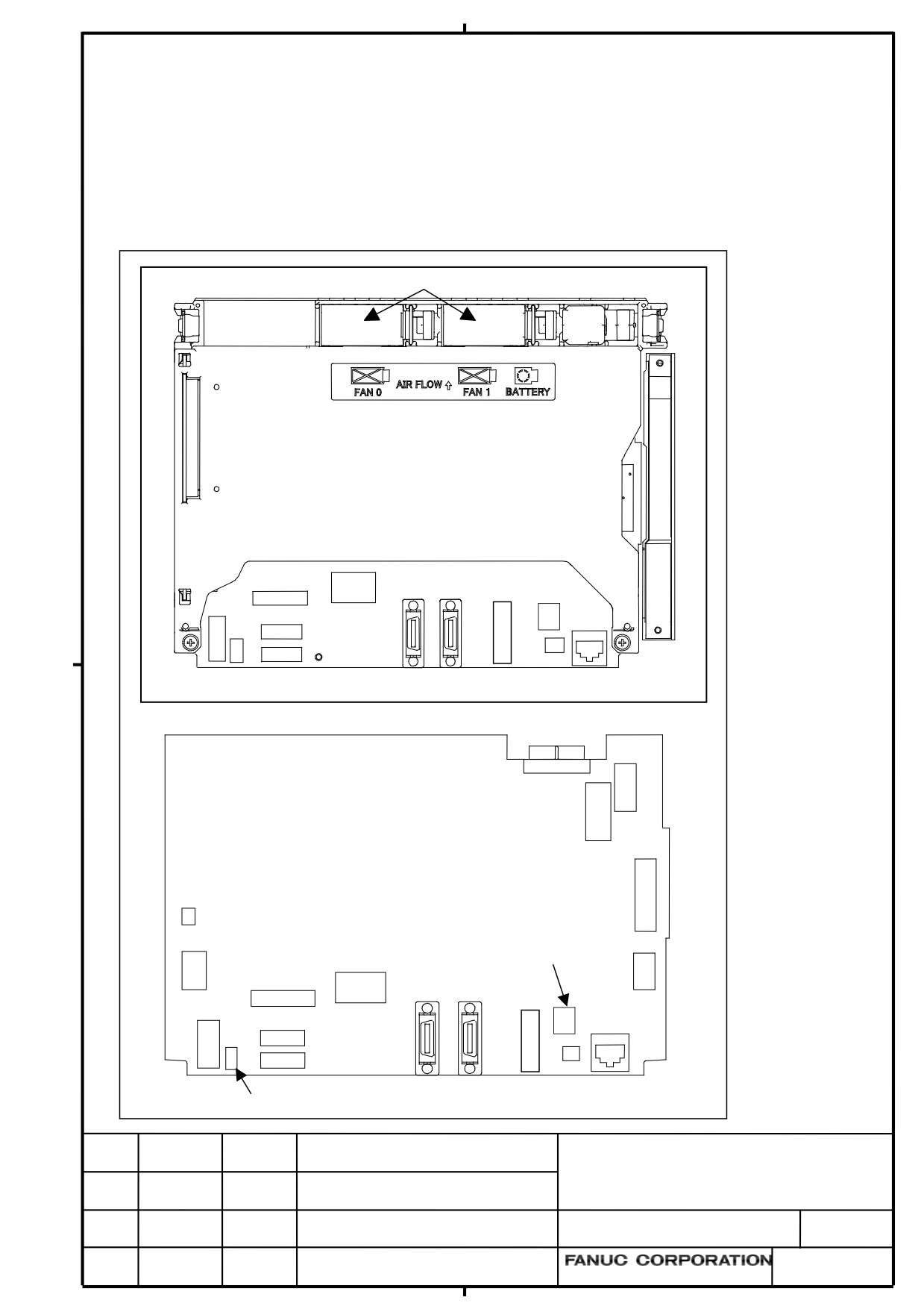
Section 2.5.3 The name of connector for buzzer was corrected.
2.5.3
Display Unit for Stand-Alone Type Control Unit (with Personal
Computer Function with Windows®CE)
z
Connector mounting location
Fan motor
Rear view
CA55
COP21M
CA136
CPD18
JD54
JD36
CA149
CD38S
CA132
CA135
CA133
CA139
Display control board
CA88A
CA134
Rotary switch
COP21M
CD46L
CA55
CA136
CPD18
CD38S
CK20A
CK21A
JD54
JD36
CA149
Fuse
Title
Series30i/31i/32i-MODEL B
The correction of maintenance manual
DRAW. NO.
CUST
B-64485EN/01-02
SHEET
EDIT
DATE
DESIG.
DESCRIPTION
7 / 9
Connector number
Application
CA55
For MDI
JD36
For I/O device interface (RS-232C)
JD54
For I/O device interface (RS-232C) or USB device
CPD18
For power supply
CA133
For video signal interface (for 10.4”/12.1” display unit)
CA135
For video signal interface (for 15” display unit)
CA88A
For memory card interface
CD46L
For USB port
CK20A
For horizontal soft key
CK21A
For vertical soft key
CA132
For inverter board (for 10.4” display unit)
For fan adapter board (for 12.1”/15” display unit)
COP21M
For HSSB interface
CD38S
For Ethernet (Windows CE control)
CA139
For touch panel interface
CA134
For inverter board (for 12.1”/15” display unit)
CA149
For buzzer interface
CA136
For backup unit
Title
Series30i/31i/32i-MODEL B
The correction of maintenance manual
DRAW. NO.
CUST
B-64485EN/01-02
SHEET
EDIT
DATE
DESIG.
DESCRIPTION
8 / 9
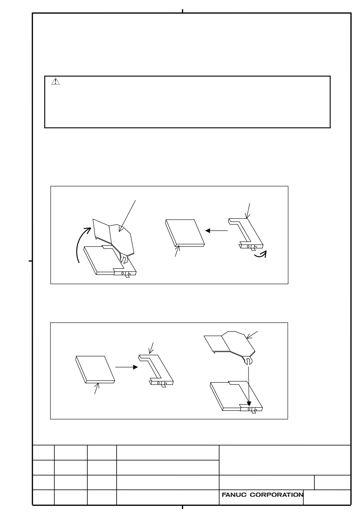
Section 3.7
The procedure of the installation and detaching the CompactFlash card was corrected.
3.7
ATTACHING A COMPACT FLASH CARD ONTO, AND
DETACHING IT FROM, A PRINTED CIRCUIT BOARD
CAUTION
Before starting to replace the compact flash card, make a backup copy of the
contents (parameters, programs, etc.) of SRAM in the CNC. The SRAM contents
may be lost during replacement. See Chapter 5, “INPUT AND OUTPUT OF
DATA”, and Appendix C, “BOOT SYSTEM” for explanations about how to make
backup copies. Also see Subsection 3.1.1, “Optional Information File”.
Some types of printed circuit boards incorporate a compact flash card. When replacing these printed
circuit boards, stick to the following procedures.
Dismounting procesure
Pull out the stopper up. Turn the latch inward and pull out the card.
Stopper
Connector
Compact
Latch
flash card
Mounting procedure
Insert the card in the connector, and put up the stopper.
Stopper
Connector
Compact
flash card
Title
Series30i/31i/32i-MODEL B
The correction of maintenance manual
DRAW. NO.
CUST
B-64485EN/01-02
SHEET
EDIT
DATE
DESIG.
DESCRIPTION
9 / 9
Addition in FANUC Series 30i-B / 31i-B / 32i-B MAINTENANCE MANUAL
1. Type of applied technical documents
Name
FANUC Series 30i-MODEL B
FANUC Series 31i-MODEL B
FANUC Series 32i-MODEL B
MAINTENANCE MANUAL
Spec.No. / Version
B-64485EN/01
2. Summary of change
Group
Name / Outline
New,
Applicable
Add,
Date
Correct,
Delete
Basic
Explanation of the alarms PS5523 and PS5524 has been
Add
Immediately
Function
added.
Optional
Function
Unit
Maintenance
parts
Notice
Notes for FROM/SRAM module replacement have
Add
Immediately
also been added.
Correction
Another
Addition in
FANUC Series 30i-B / 31i-B / 32i-B
MAINTENANCE MANUAL
CUST.
01
11.11.18
Kobayashi
New issue
DRAW. NO. B-64485EN/01-03
SHEET
Edit.
DATE
Design
Description
1 / 5
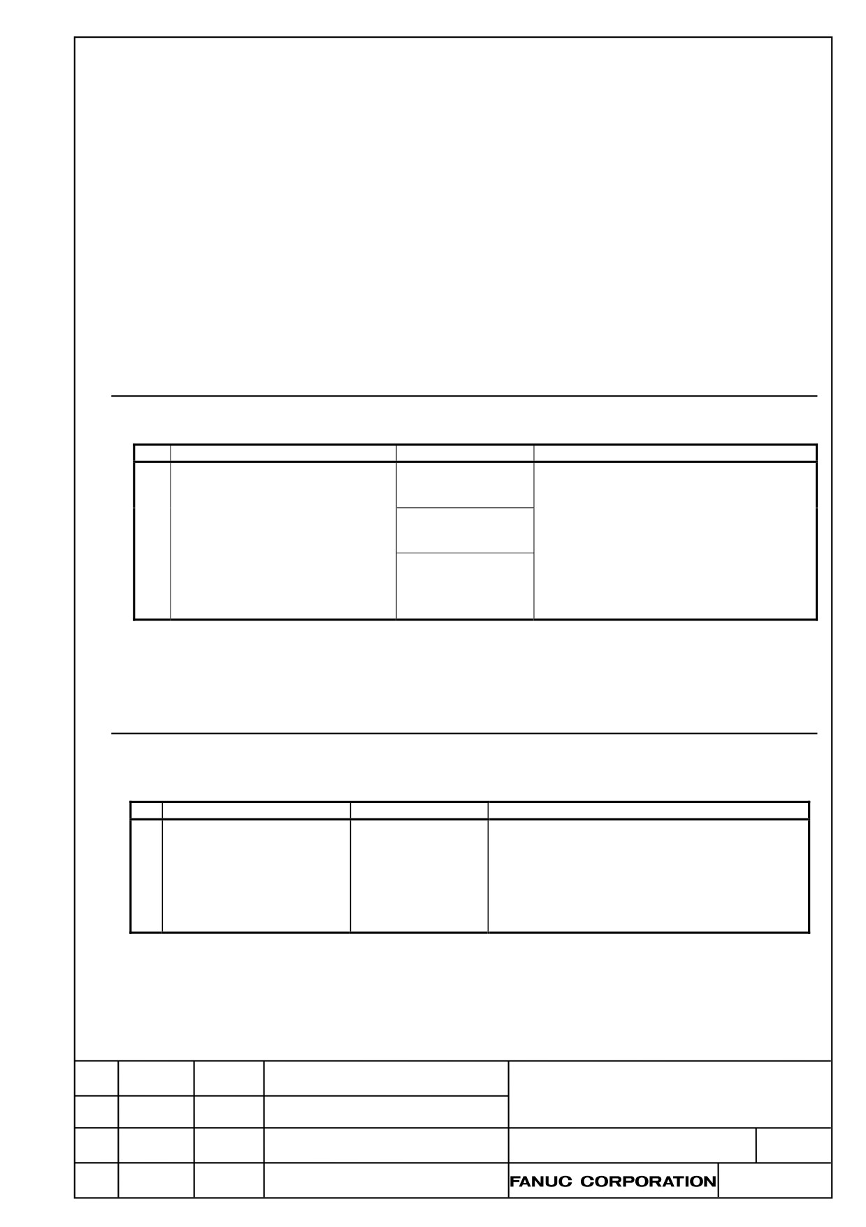
We add the specification of FROM/SRAM module in the P.C.B. list at the following paragraph.
2.4.1 LCD-mounted Type Control Unit (8.4” LCD Unit and 10.4” LCD Unit A)
2.4.2 LCD-mounted Type Control Unit (10.4” LCD Unit B and 15” LCD Unit)
2.4.3 LCD-mounted Type Control Unit (with Personal Computer Function with
Windows®CE) Hardware
2.5.1 Stand-alone Type Control Unit
3.1
CAUTIONS FOR REPLACEMENT
3.6
MOUNTING AND DEMOUNTING FROM/SRAM MODULE
B.3
PRINTED CIRCUIT BOARDS COMMON TO LCD-MOUNTED AND STAND-ALONE
TYPE CONTROL UNITS
2.4.1
LCD-mounted Type Control Unit (8.4” LCD Unit and 10.4”
LCD Unit A)
(P.173)
No.
Name
Specification
Remark
(4)
FROM/SRAM module
A20B-3900-0250
The FROM stores various control software
programs, user software programs, and so
A20B-3900-0251
forth. The SRAM is a battery-backed
memory module.
A20B-3900-0252
When a FROM/SRAM module is replaced,
the FANUC service division installs system
software.
2.4.2
LCD-mounted Type Control Unit (10.4” LCD Unit B and 15”
LCD Unit)
(P.182)
No.
Name
Specification
Remark
(1)
FROM/SRAM module
A20B-3900-0260
The FROM stores various control software
programs, user software programs, and so forth.
The SRAM is a battery-backed memory module.
When a FROM/SRAM module is replaced, the
FANUC service division installs system software.
Addition in
FANUC Series 30i-B / 31i-B / 32i-B
MAINTENANCE MANUAL
CUST.
DRAW. NO. B-64485EN/01-03
Edit.
DATE
Design
Description
SHEET
2 / 5
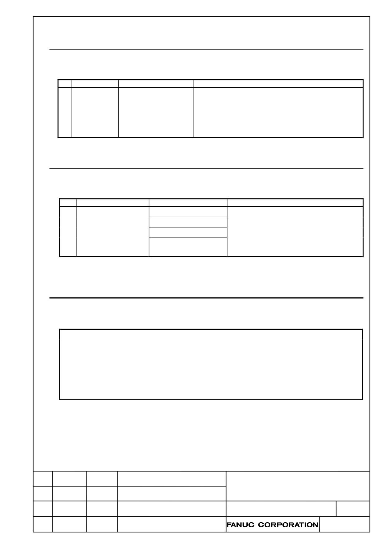
2.4.3
LCD-mounted Type Control Unit (with Personal Computer
Function with Windows®CE) Hardware
(P.191)
No.
Name
Specification
Remark
(1)
FROM/SRAM
A20B-3900-0260
The FROM stores various control software programs, user
module
software programs, and so forth.
The SRAM is a battery-backed memory module.
When a FROM/SRAM module is replaced, the FANUC
service division installs system software.
2.5.1
Stand-alone Type Control Unit
(P.200)
No.
Name
Specification
Remark
(3)
FROM/SRAM module
A20B-3900-0250
FROM stores various control software products.
A20B-3900-0251
The SRAM is a battery-backed memory module.
A20B-3900-0252
When a FROM/SRAM module is replaced, the
A20B-3900-0260
FANUC service division installs system
software.
3.1
CAUTIONS FOR REPLACEMENT
(P.250)
NOTE
1 When a FROM/SRAM module is replaced, the FANUC service division
installs system software.
2 The LCD (liquid-crystal display) has been fabricated using an extreme
precision technology. However, some of their pixels may fail to light or stay
constantly lighting because of their characteristics. Please be forewarned
that these phenomena are not faults.
Addition in
FANUC Series 30i-B / 31i-B / 32i-B
MAINTENANCE MANUAL
CUST.
DRAW. NO. B-64485EN/01-03
Edit.
DATE
Design
Description
SHEET
3 / 5
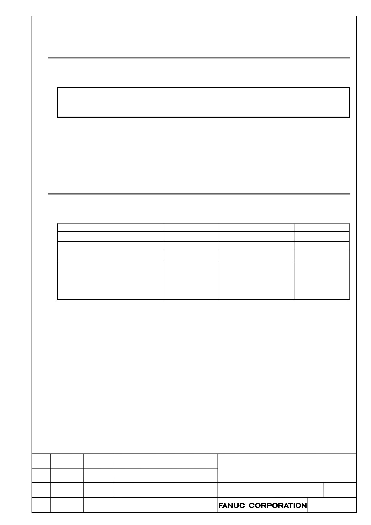
3.6
MOUNTING AND DEMOUNTING FROM/SRAM MODULE
(P.261)
NOTE
When a FROM/SRAM module is replaced, the FANUC service division
installs system software.
B.3 PRINTED CIRCUIT BOARDS COMMON TO
LCD-MOUNTED AND STAND-ALONE TYPE CONTROL
UNITS
(P.735,736)
Item
Specification
ID
Remark
FROM/SRAM module O
A02B-3900-0250
FROM: D4, SRAM: 03
FROM/SRAM module P
A02B-3900-0251
FROM: D4, SRAM: 04
FROM/SRAM module M
A02B-3900-0252
FROM: D3, SRAM: 03
FROM/SRAM module R
A20B-3900-0260
FROM: D4, SRAM: 06
For personal
computer function
with Windows® CE
* When a FROM/SRAM module is replaced, the FANUC service division installs system software.
Addition in
FANUC Series 30i-B / 31i-B / 32i-B
MAINTENANCE MANUAL
CUST.
DRAW. NO. B-64485EN/01-03
Edit.
DATE
Design
Description
SHEET
4 / 5
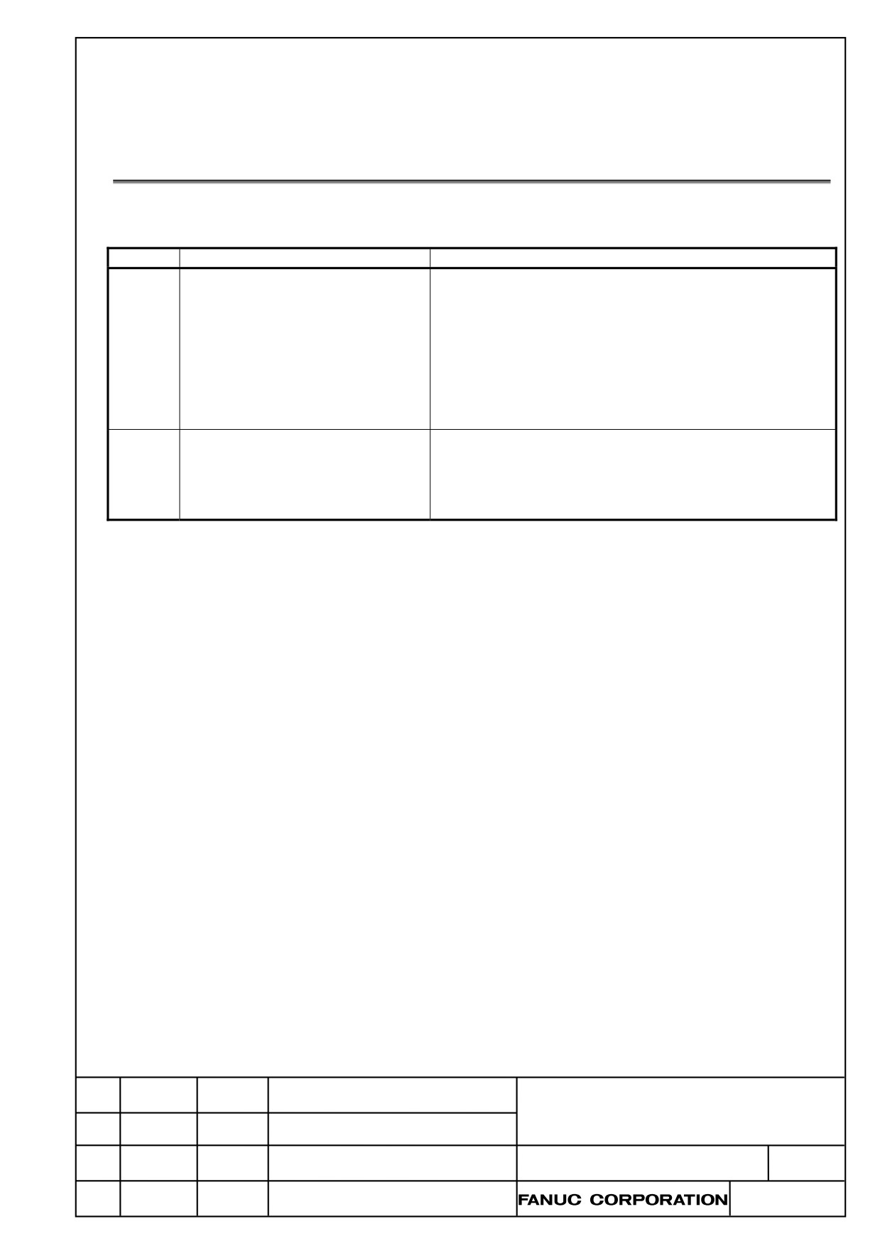
Add the following description to the table of the PS/BG/SR alarm in the appendix A.1 ALARM
LIST (CNC)
A.1 ALARM LIST(CNC)
(P.663)
Number
Message
Description
5523
WAITING THE OPTION
CNC is under the option certification waiting state.
CERTIFICATION
・ This alarm can be cleared by the reset operation before
the expiration date (30 days after generating the alarm).
・ As for the certification operation to clear this alarm
permanently, please contact the FANUC service division
by the above date.
・ When the certification operation is not executed by the
expiration date, the alarm PS5524 occurs. This alarm
cannot be cleared by the reset operation.
5524
OPTION CERTIFICATION (EXPIRE)
The option certification waiting state was expired.
・ This alarm cannot be cleared by the reset operation.
・ As for the certification operation to clear this alarm
permanently, please contact the FANUC service
division.
Addition in
FANUC Series 30i-B / 31i-B / 32i-B
MAINTENANCE MANUAL
CUST.
DRAW. NO. B-64485EN/01-03
Edit.
DATE
Design
Description
SHEET
5 / 5