FANUC Series 30i-MODEL B, 31i-MODEL B, 32i-MODEL B. MAINTENANCE MANUAL - page 26
B. LISTS OF UNITS, PRINTED CIRCUIT
BOARDS, AND CONSUMABLES
APPENDIX
B-64485EN/01
Display unit
-
Display unit with 10.4” LCD unit A
Item
Name
Specification
Remark
Display unit
Display control board
A20B-8200-0760
ID=00620
A02B-0323-C074
Inverter board (for 10.4” LCD unit)
A20B-8200-0662
ID=1010
10.4"LCD unit A
A02B-0323-D500
Display unit
Display control board
A20B-8200-0760
ID=00620
(with protection cover)
Inverter board (for 10.4” LCD unit)
A20B-8200-0662
ID=1010
A02B-0323-C075
10.4"LCD unit A (with protection cover)
A02B-0323-D574
Display unit
Display control board
A20B-8200-0760
ID=00620
(with touch panel)
Inverter board (for 10.4” LCD unit)
A20B-8200-0662
ID=1010
A02B-0323-C084
Touch panel control board
A20B-8002-0312
Touch panel cable
A660-2042-T145#L200R0
10.4"LCD unit A (with touch panel)
A02B-0323-D570
Display unit
Display control board
A20B-8200-0760
ID=00620
(with touch panel and protection
Inverter board (for 10.4” LCD unit)
A20B-8200-0662
cover)
A02B-0323-C085
10.4"LCD unit A
A02B-0323-D572
(with touch panel and protection cover)
First LCD unit for 2-display unit
Display control board
A20B-8200-0761
ID=00621
Inverter board (for 10.4” LCD unit)
A20B-8200-0662
ID=1010
A02B-0323-C072
10.4"LCD unit A
A02B-0323-D500
First LCD unit for 2-display unit
Display control board
A20B-8200-0761
ID=00621
(with protection cover)
Inverter board (for 10.4” LCD unit)
A20B-8200-0662
ID=1010
A02B-0323-C076
10.4"LCD unit A (with protection cover)
A02B-0323-D574
Second LCD unit for 2-display
Display control board
A20B-8200-0762
unit
Inverter board (for 10.4” LCD unit)
A20B-8200-0662
ID=1010
A02B-0323-C073
10.4"LCD unit A
A02B-0323-D521
(as the second LCD unit for 2-display unit)
Second LCD unit for 2-display
Display control board
A20B-8200-0762
unit
(with protection cover)
Inverter board (for 10.4” LCD unit)
A20B-8200-0662
ID=1010
A02B-0323-C077
10.4"LCD unit A
A02B-0323-D576
(as the second LCD unit for 2-display unit,
with protection cover)
-
Display unit with 10.4”LCD unit B
Item
Name
Specification
Remark
Display unit
Display control board
A20B-8200-0746
A02B-0323-C078
Compact flash card
A02B-0323-C990#A
Inverter board
A20B-8200-0662
10.4"LCD unit B
A02B-0323-D540
ID=0111
Power supply unit
A20B-8101-0011
Display unit
Display control board
A20B-8200-0746
(with touch panel)
Compact flash card
A02B-0323-C990#A
A02B-0323-C079
Inverter board
A20B-8200-0662
10.4"LCD unit B (with touch panel)
A02B-0323-D542
ID=0111
Power supply unit
A20B-8101-0011
Display unit
Display control board
A20B-8200-0746
(with protection cover)
Compact flash card
A02B-0323-C990#A
A02B-0323-C088
Inverter board
A20B-8200-0662
10.4"LCD unit B (with protection cover)
A02B-0323-D550
ID=0111
Power supply unit
A20B-8101-0011
- 732 -
B.LISTS OF UNITS, PRINTED CIRCUIT
B-64485EN/01
APPENDIX
BOARDS, AND CONSUMABLES
Item
Name
Specification
Remark
Display unit
Display control board
A20B-8200-0746
(with touch panel and protection
Compact flash card
A02B-0323-C990#A
cover)
A02B-0323-C089
Inverter board
A20B-8200-0662
10.4"LCD unit B
A02B-0323-D552
ID=0111
(with touch panel and protection cover)
Power supply unit
A20B-8101-0011
-
Display unit with 15”LCD unit
Item
Name
Specification
Remark
Display unit
Display control board
A20B-8200-0742
A02B-0323-C091
Compact flash card
A02B-0323-C990#A
Including software
Power supply unit
A20B-8101-0011
Inverter board
A14L-0168-0001
Connection cable between display
A660-4042-T076#L75R00
control board and inverter board
Fan adapter board
A20B-8200-0669
15”LCD unit
A02B-0323-D546
ID=0101
Display unit
Display control board
A20B-8200-0742
(with touch panel)
Compact flash card
A02B-0323-C990#A
Including software
A02B-0323-C092
Power supply unit
A20B-8101-0011
Inverter board
A14L-0168-0001
Connection cable between display
A660-4042-T076#L75R00
control board and inverter board
Fan adapter board
A20B-8200-0669
15”LCD unit (with touch panel)
A02B-0323-D548
ID=0101
Display unit
Display control board
A20B-8200-0742
(with protection cover)
Compact flash card
A02B-0323-C990#A
Including software
A02B-0323-C095
Power supply unit
A20B-8101-0011
Inverter board
A14L-0168-0001
Connection cable between display
A660-4042-T076#L75R00
control board and inverter board
Fan adapter board
A20B-8200-0669
15”LCD unit (with protection cover)
A20B-0323-D556
ID=0101
Display unit
Display control board
A20B-8200-0742
(with touch panel and
Compact flash card
A02B-0323-C990#A
Including software
protection cover)
Power supply unit
A20B-8101-0011
A02B-0323-C096
Inverter board
A14L-0168-0001
Connection cable between display
A660-4042-T076#L75R00
control board and inverter board
Fan adapter board
A20B-8200-0669
15”LCD unit
A20B-0323-D558
ID=0101
(with touch panel and protection
cover)
- 733 -
B. LISTS OF UNITS, PRINTED CIRCUIT
BOARDS, AND CONSUMABLES
APPENDIX
B-64485EN/01
-
Display unit for automotive manufacture
Item
Name
Specification
Remark
15” display unit
Display control board
A20B-8200-0745
A13B-0201-B201
Compact flash card
A02B-0323-C990#B
Including software
Power supply unit
A20B-8101-0011
Inverter board
A14L-0168-0001
Connection cable between display
A660-4042-T076#L75R00
control board and inverter board
Fan adapter board
A20B-8200-0669
LCD unit
A13B-0201-D201
ID=0101
15” display unit
Display control board
A20B-8200-0745
(with touch panel)
Compact flash card
A02B-0323-C990#B
Including software
A13B-0201-B202
Power supply unit
A20B-8101-0011
Inverter board
A14L-0168-0001
Connection cable between display
A660-4042-T076#L75R00
control board and inverter board
Fan adapter board
A20B-8200-0669
LCD unit (with touch panel)
A13B-0201-D202
ID=0101
15” display unit
Display control board
A20B-8200-0745
(with protection cover)
Compact flash card
A02B-0323-C990#B
Including software
A13B-0201-B203
Power supply unit
A20B-8101-0011
Inverter board
A14L-0168-0001
Connection cable between display
A660-4042-T076#L75R00
control board and inverter board
Fan adapter board
A20B-8200-0669
LCD unit (with protection cover)
A13B-0201-D203
ID=0101
15” display unit
Display control board
A20B-8200-0745
(with
touch
panel
and
Compact flash card
A02B-0323-C990#B
Including software
protection cover)
A13B-0201-B204
Power supply unit
A20B-8101-0011
Inverter board
A14L-0168-0001
Connection cable between display
A660-4042-T076#L75R00
control board and inverter board
Fan adapter board
A20B-8200-0669
LCD unit
A13B-0201-D204
ID=0101
(with touch panel and protection
cover)
15” display unit
Display control board
A20B-8200-0745
(with I/O Link)
Compact flash card
A02B-0323-C990#B
Including software
A13B-0201-B211
Power supply unit
A20B-8101-0011
Inverter board
A14L-0168-0001
Connection cable between display
A660-4042-T076#L75R00
control board and inverter board
Fan adapter board
A20B-8200-0669
I/O Link adapter board
A20B-8002-0500
DC power cable
A660-2005-T779#160R0
LCD unit
A13B-0201-D211
ID=0101
- 734 -
B.LISTS OF UNITS, PRINTED CIRCUIT
B-64485EN/01
APPENDIX
BOARDS, AND CONSUMABLES
Item
Name
Specification
Remark
15” display unit
Display control board
A20B-8200-0745
(with touch panel and I/O Link)
Compact flash card
A02B-0323-C990#B
Including software
A13B-0201-B212
Power supply unit
A20B-8101-0011
Inverter board
A14L-0168-0001
Connection cable between display
A660-4042-T076#L75R00
control board and inverter board
Fan adapter board
A20B-8200-0669
I/O Link adapter board
A20B-8002-0500
DC power cable
A660-2005-T779#160R0
LCD unit (with touch panel)
A13B-0201-D212
ID=0101
15” display unit
Display control board
A20B-8200-0745
(with I/O Link and protection
Compact flash card
A02B-0323-C990#B
Including software
cover)
A13B-0201-B213
Power supply unit
A20B-8101-0011
Inverter board
A14L-0168-0001
Connection cable between display
A660-4042-T076#L75R00
control board and inverter board
Fan adapter board
A20B-8200-0669
I/O Link adapter board
A20B-8002-0500
DC power cable
A660-2005-T779#160R0
LCD unit (with protection cover)
A13B-0201-D213
ID=0101
15” display unit
Display control board
A20B-8200-0745
(with touch panel, I/O Link, and
Compact flash card
A02B-0323-C990#B
Including software
protection cover)
Power supply unit
A20B-8101-0011
A13B-0201-B214
Inverter board
A14L-0168-0001
Connection cable between display
A660-4042-T076#L75R00
control board and inverter board
Fan adapter board
A20B-8200-0669
I/O Link adapter board
A20B-8002-0500
DC power cable
A660-2005-T779#160R0
LCD unit
A13B-0201-D214
ID=0101
(with touch panel and protection
cover)
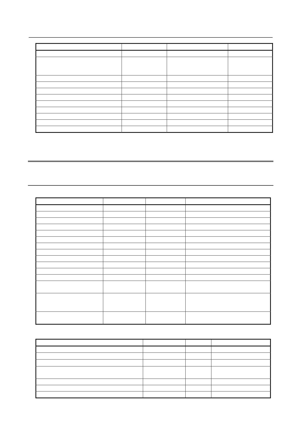
B.3 PRINTED CIRCUIT BOARDS COMMON TO
LCD-MOUNTED AND STAND-ALONE TYPE CONTROL
UNITS
Item
Specification
ID
Remark
CPU card A1
A20B-3300-0652
00442
CPU card A2
A20B-3300-0653
00443
CPU card B1
A20B-3300-0650
00440
CPU card B2
A20B-3300-0651
00441
CPU card C1
A20B-3300-0654
00444
CPU card C2
A20B-3300-0655
00445
Servo card A11
A20B-3300-0664
00155
Servo card A12
A20B-3300-0663
00154
Servo card A13
A20B-3300-0662
00153
Servo card A24
A20B-3300-0661
00152
Servo card A26
A20B-3300-0660
00151
FROM/SRAM module O
A02B-3900-0250
FROM: D4, SRAM: 03
FROM/SRAM module P
A02B-3900-0251
FROM: D4, SRAM: 04
- 735 -
B. LISTS OF UNITS, PRINTED CIRCUIT
BOARDS, AND CONSUMABLES
APPENDIX
B-64485EN/01
Item
Specification
ID
Remark
FROM/SRAM module M
A02B-3900-0252
FROM: D3, SRAM: 03
FROM/SRAM module R
A20B-3900-0260
FROM: D4, SRAM: 06
For personal
computer function
with Windows® CE
GUI card (DDR SDRAM 128MB)
A20B-3300-0670
1110
Additional axis board
A20B-8101-0740
00161
HSSB interface board
A20B-8101-0111
00611
Fast Ethernet board
A20B-8101-0770
0070E
PROFIBUS-DP master board
A20B-8101-0050
00704
PROFIBUS-DP slave board
A20B-8101-0100
00705
DeviceNet master board
A20B-8101-0220
00706
DeviceNet slave board
A20B-8101-0330
00708
CC-Link remote device station board
A20B-8101-0551
-
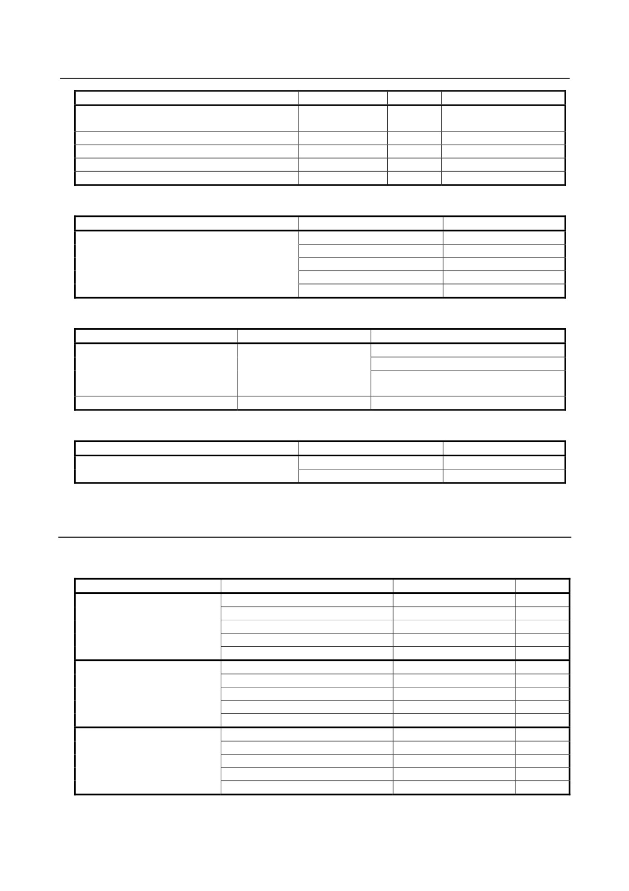
B.4 PRINTED CIRCUIT BOARDS AND UNITS UNIQUE TO
PERSONAL COMPUTER FUNCTION WITH Windows® CE
B.4.1 Personal computer function with Windows® CE for
LCD-mounted type Control Unit
List of printed circuit boards
Item
Specification
ID
Remark
Main board C1
A20B-8200-0710
00350
Main board C7
A20B-8200-0700
00340
Main board C4
A20B-8200-0714
00354
Main board C10
A20B-8200-0704
00344
Main board C3
A20B-8200-0713
00353
Main board C9
A20B-8200-0703
00343
Main board C6
A20B-8200-0717
00357
Main board C12
A20B-8200-0707
00347
Main board C2
A20B-8200-0711
00351
Main board C8
A20B-8200-0701
00341
Main board C5
A20B-8200-0715
00355
Main board C11
A20B-8200-0705
00345
GUI card
A20B-3300-0671
1111
See Section B.3 for descriptions of the
(DDR SDRAM 256MB)
GUI card (DDR SDRAM 128MB).
Inverter board
A14L-0143-0003
-
See Section B.1 for descriptions of the
(for 12.1” LCD unit)
inverter board for the 10.4” and 15” LCD
units.
Fan adapter board
A20B-8200-0669
-
(for 12.1” or 15” LCD unit)
List of units
Item
Specification
ID
Remark
10.4” LCD unit
A02B-0323-D505
1111
10.4” LCD unit (with touch panel)
A02B-0323-D507
1111
10.4” LCD unit (with protection cover)
A02B-0323-D525
1111
10.4” LCD unit (with touch panel and protection
A02B-0323-D527
1111
cover)
12.1” LCD unit
A02B-0323-D508
1110
12.1” LCD unit (with touch panel)
A02B-0323-D510
1110
12.1” LCD unit (with protection cover)
A02B-0323-D528
1110
- 736 -
B.LISTS OF UNITS, PRINTED CIRCUIT
B-64485EN/01
APPENDIX
BOARDS, AND CONSUMABLES
Item
Specification
ID
Remark
12.1” LCD unit (with touch panel and protection
A02B-0323-D530
1110
cover)
15” LCD unit
A02B-0323-D515
1101
15” LCD unit (with touch panel)
A02B-0323-D517
1101
15” LCD unit (with protection cover)
A02B-0323-D535
1101
15” LCD unit (with touch panel and protection cover)
A02B-0323-D537
1101
Compact flash cards on printed circuit boards
Item
Specification
Remark
Compact flash card
A87L-0001-0173#128MBD
Total capacity: 128MB
A87L-0001-0173#256MBD
Total capacity: 256MB
A87L-0001-0173#512MBD
Total capacity: 512MB
A87L-0001-0173#001GBD
Total capacity: 1GB
A87L-0001-0173#002GBD
Total capacity: 2GB
Backup unit
Item
Specification
Remark
Backup unit
A20B-2100-0820
For installation on the rear of the MDI unit
For installation inside a cabinet.
For installation on the rear of the MDI unit
(QWRTY TYPE B)
Cable for backup unit
A660-4042-T078#L500R0A
Others
Item
Specification
Remark
Connection cable between main board and inverter
A660-4042-0075#L90R00
For 12.1” LCD unit
board
A660-4042-0076#L75R00
For 15" LCD unit
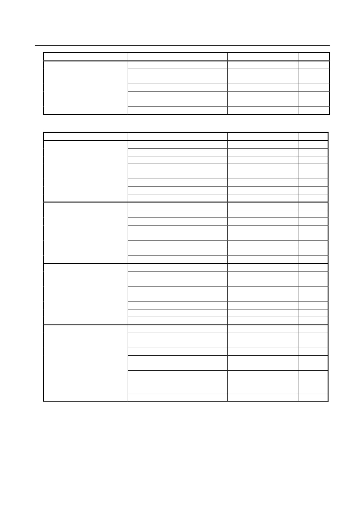
B.4.2 Personal computer function with Windows® CE for
Stand-alone type Control Unit
Display unit
・ Display unit with 10.4” LCD unit
Item
Name
Specification
Remark
Display unit
Display control board
A20B-8200-0740
A13B-0201-B001
Power supply unit
A20B-8101-0011
Inverter board
A20B-8200-0662
10.4”LCD unit
A02B-0323-D540
ID=1111
Case
A02B-0323-D100#0A
Display unit
Display control board
A20B-8200-0740
(with touch panel)
Power supply unit
A20B-8101-0011
A13B-0201-B003
Inverter board
A20B-8200-0662
10.4”LCD unit (with touch panel)
A02B-0323-D542
ID=1111
Case
A02B-0323-D100#0A
Display unit
Display control board
A20B-8200-0740
(with protection cover)
Power supply unit
A20B-8101-0011
A13B-0201-B004
Inverter board
A20B-8200-0662
10.4”LCD unit (with protection cover)
A02B-0323-D550
ID=1111
Case
A02B-0323-D100#0A
- 737 -
B. LISTS OF UNITS, PRINTED CIRCUIT
BOARDS, AND CONSUMABLES
APPENDIX
B-64485EN/01
Item
Name
Specification
Remark
Display unit
Display control board
A20B-8200-0740
(with touch panel and protection
Power supply unit
A20B-8101-0011
cover)
A13B-0201-B006
Inverter board
A20B-8200-0662
10.4”LCD unit
A02B-0323-D552
ID=1111
(with touch panel and protection cover)
Case
A02B-0323-D100#0A
・ Display unit with 12.1” LCD unit
Item
Name
Specification
Remark
Display unit
Display control board
A20B-8200-0743
A13B-0201-B011
Power supply unit
A20B-8101-0011
Inverter board
A14L-0143-0003
Connection cable between display
A660-4042-T075#L90R00
control board and inverter board
Fan adapter board
A20B-8200-0669
12.1”LCD unit
A02B-0323-D543
ID=1110
Case
A02B-0323-D100#0A
Display unit
Display control board
A20B-8200-0743
(with touch panel)
Power supply unit
A20B-8101-0011
A13B-0201-B013
Inverter board
A14L-0143-0003
Connection cable between display
A660-4042-T075#L90R00
control board and inverter board
Fan adapter board
A20B-8200-0669
12.1”LCD unit (with touch panel)
A02B-0323-D545
ID=1110
Case
A02B-0323-D100#0A
Display unit
Display control board
A20B-8200-0743
(with protection cover)
Power supply unit
A20B-8101-0011
A13B-0201-B014
Inverter board
A14L-0143-0003
Connection cable between display
A660-4042-T075#L90R00
control board and inverter board
Fan adapter board
A20B-8200-0669
12.1”LCD unit (with protection cover)
A02B-0323-D553
ID=1110
Case
A02B-0323-D100#0A
Display unit
Display control board
A20B-8200-0743
(with touch panel and protection
Power supply unit
A20B-8101-0011
cover)
A13B-0201-B016
Inverter board
A14L-0143-0003
Connection cable between display
A660-4042-T075#L90R00
control board and inverter board
Fan adapter board
A20B-8200-0669
12.1”LCD unit
A02B-0323-D555
ID=1110
(with touch panel and protection cover)
Case
A02B-0323-D100#0A
- 738 -
B.LISTS OF UNITS, PRINTED CIRCUIT
B-64485EN/01
APPENDIX
BOARDS, AND CONSUMABLES
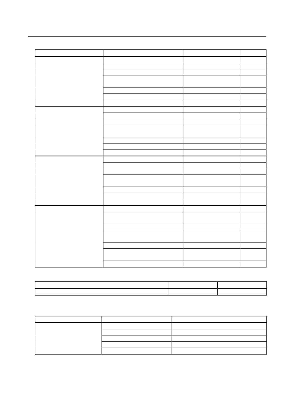
・ Display unit with 15” LCD unit
Item
Name
Specification
Remark
Display unit
Display control board
A20B-8200-0741
A13B-0201-B021
Power supply unit
A20B-8101-0011
Inverter board
A14L-0168-0001
Connection cable between display
A660-4042-T076#L75R00
control board and inverter board
Fan adapter board
A20B-8200-0669
15”LCD unit
A02B-0323-D546
ID=1101
Case
A02B-0323-D100#0A
Display unit
Display control board
A20B-8200-0741
(with touch panel)
Power supply unit
A20B-8101-0011
A13B-0201-B023
Inverter board
A14L-0168-0001
Connection cable between display
A660-4042-T076#L75R00
control board and inverter board
Fan adapter board
A20B-8200-0669
15”LCD unit (with touch panel)
A02B-0323-D548
ID=1101
Case
A02B-0323-D100#0A
Display unit
Display control board
A20B-8200-0741
(with protection cover)
Power supply unit
A20B-8101-0011
A13B-0201-B024
Inverter board
A14L-0168-0001
Connection cable between display
A660-4042-T076#L75R00
control board and inverter board
Fan adapter board
A20B-8200-0669
15”LCD unit (with protection cover)
A02B-0323-D556
ID=1101
Case
A02B-0323-D100#0A
Display unit
Display control board
A20B-8200-0741
(with touch panel and protection
Power supply unit
A20B-8101-0011
cover)
A13B-0201-B026
Inverter board
A14L-0168-0001
Connection cable between display
A660-4042-T076#L75R00
control board and inverter board
Fan adapter board
A20B-8200-0669
15”LCD unit
A02B-0323-D558
ID=1101
(with touch panel and protection cover)
Case
A02B-0323-D100#0A
GUI card
Item
Specification
Remark
GUI カード(DDR SDRAM 256MB)
A20B-3300-0671
ID=1111
* See Section B.3 for descriptions of the GUI card (DDR SDRAM 128MB).
Compact flash cards on printed circuit boards
Item
Specification
Remark
Compact flash card
A87L-0001-0173#128MBD
Total capacity: 128MB
A87L-0001-0173#256MBD
Total capacity: 256MB
A87L-0001-0173#512MBD
Total capacity: 512MB
A87L-0001-0173#001GBD
Total capacity: 1GB
A87L-0001-0173#002GBD
Total capacity: 2GB
- 739 -
B. LISTS OF UNITS, PRINTED CIRCUIT
BOARDS, AND CONSUMABLES
APPENDIX
B-64485EN/01
Backup unit
Item
Specification
Remark
Backup unit
A02B-0303-H160
For installation on the rear of the MDI unit
A02B-0303-C161
For installation inside a cabinet.
A02B-0303-H164
For installation on the rear of the MDI unit (QWRTY TYPE B)
Cable for backup unit
A02B-0323-K801
B.5 MDI UNIT
Item
Specification
ID
Remark
Small MDI unit (for lathe system, ONG, 8.4” LCD unit)
A02B-0323-C120#T
04
Small MDI unit (for machining center system, ONG, 8.4” LCD unit)
A02B-0323-C120#M
08
Standard MDI unit (for lathe system, ONG, 8.4” display unit)
A02B-0323-C121#T
40
Standard MDI unit (for machining center system, ONG, 8.4” LCD unit)
A02B-0323-C121#M
02
Standard MDI unit (for lathe system, ONG, horizontal type)
A02B-0323-C125#T
40
Standard MDI unit (for machining center system, ONG, Horizontal type)
A02B-0323-C125#M
02
Standard MDI unit (lathe system, ONG, Vertical type)
A02B-0323-C126#T
40
Standard MDI unit (machining center system, ONG, vertical type)
A02B-0323-C126#M
02
Standard MDI unit (QWERTY)
A02B-0323-C128
20
Standard MDI unit (QWERTY TYPE B)
A02B-0323-C129
21
B.6 OTHER UNITS
Item
Specification
Remark
I/O module for connector panel
A03B-0824-C001
DI/DO : 24/16
(basic module)
I/O module for connector panel
DI/DO : 24/16
A03B-0824-C002
(extension module A)
With manual pulse generator interface
I/O module for connector panel
DI/DO : 24/16
A03B-0824-C003
(extension module B)
Without manual pulse generator interface
I/O module for connector panel
DO : 16
A03B-0824-C004
(extension module C)
2A output module
I/O module for connector panel
A03B-0824-C005
Analog input module
(extension module D)
Cable length: 20mm
Flat cable between modules for I/O module for
A03B-0815-K100
Applicable to an inter-module distance of
connector panel
32 mm
I/O module for operator’s panel
A03B-0824-K200
I/O module for operator’s panel
DI/DO : 48/32
A03B-0824-K202
(with MPG interface)
With manual pulse generator interface
I/O module for power magnetics cabinet
DI/DO : 48/32
A03B-0824-K203
(without MPG interface)
Without manual pulse generator interface
I/O module type-2 for connector panel
A03B-0824-C040
DI/DO : 48/32
(basic module B1)
With manual pulse generator interface
I/O module type-2 for connector panel
A03B-0824-C041
DI/DO : 48/32
(basic module B2)
Without manual pulse generator interface
I/O module type-2 for connector panel
A03B-0824-C042
DI/DO : 48/32
(extension module E1)
Flat cable between modules for I/O module type-2 forA03B-0815-K102
Cable length: 35mm
connector panel
Inter-module distance: 5mm
- 740 -

B.LISTS OF UNITS, PRINTED CIRCUIT
B-64485EN/01
APPENDIX
BOARDS, AND CONSUMABLES
Item
Specification
Remark
Terminal type I/O module
DI/DO : 24/16
A03B-0823-C011
Basic module
Terminal type I/O module
DI/DO : 24/16
A03B-0823-C012
Extension module A
With manual pulse generator interface
Terminal type I/O module
DI/DO : 24/16
A03B-0823-C013
Extension module B
Without manual pulse generator interface
Terminal type I/O module
DO : 16
A03B-0823-C014
Extension module C
2A output module
Terminal type I/O module
A03B-0823-C015
Analog input module
Extension module D
Terminal type I/O module
A03B-0823-C016
Analog output module
Extension module E
Spare terminals set
A03B-0823-K020
Terminal block for cable side
(for basic and extension module A/B)
(With one piece of each of T1 to T4
included)
Spare terminals set
A03B-0823-K011
Terminal block for cable side for
(for extension module C)
extension module C (With one piece of
each of T1 and T2 included)
Spare terminals set
A03B-0823-K012
Terminal block for cable side for
(for extension module D)
extension module D (With one piece of
each of T1 and T2 included)
Spare terminals set
A03B-0823-K013
Terminal block for cable side for
(for extension module E)
extension module E (With one piece of
each of T1 and T2 included)
Flat cable A between modules for terminal type I/O
A03B-0823-K100
Cable length: 100mm, 52 pins
module
Used to connect an extension module
I/O Link connection unit
A02B-0333-C250
Machine operator's panel: Main panel
A02B-0323-C231
Machine operator's panel: Sub panel A
A02B-0236-C232
Machine operator's panel: Sub panel D
A02B-0236-C244
FANUC I/O Link-AS-i converter
A03B-0817-C001
(for AS-i Ver.2.0)
FANUC I/O Link-AS-i converter
A03B-0817-C002
(for AS-i Ver.2.1)
I/O Link signal divider (2ch)
A20B-1007-0680
I/O Link signal divider (3ch)
A20B-1008-0360
Separate detector interface unit (basic 4 axes)
A02B-0323-C205
Separate detector interface unit (additional 4 axes)
A02B-0323-C204
Analog input separate detector interface unit (basic
A06B-6061-C202
4 axes)
Optical I/O Link adapter
A13B-0154-B001
Optical I/O Link adapter (high-speed type)
A13B-0154-B004
Optical junction adapter for I/O Link
A63L-0020-0002
Low-loss optical junction adapter
A63L-0020-0004
Battery case installed outside for control (for
A02B-0236-C282
LCD-mounted type control unit)
Cable for battery case installed outside for control
A02B-0323-K103
(for LCD-mounted type control unit)
Battery case installed outside for control (for
A02B-0236-C281
With cable for battery
stand-alone type control unit)
Compact flash card (128MB)
A02B-0281-K601
For data backup
For Date Server
Compact flash card (256MB)
A02B-0213-K211
For data backup
For Date Server
- 741 -
B. LISTS OF UNITS, PRINTED CIRCUIT
BOARDS, AND CONSUMABLES
APPENDIX
B-64485EN/01
Item
Specification
Remark
Compact flash card (1GB)
A02B-0213-K212
For data backup
For Date Server
Compact flash card (2GB)
A02B-0213-K213
For data backup
For Date Server
Compact flash card (4GB)
A02B-0213-K214
For Date Server
Compact flash card adapter A
A02B-0303-K150
Compact flash card adapter B
A02B-0236-K150
Adapter which converts the compact flash
card to the ATA card.
PC-side HSSB interface board (2CH.) Compatible
A20B-8101-0162
with the PCI bus
PC-side HSSB interface board (1CH.) Compatible
A20B-8101-0163
with the PCI bus
B.7
Consumables
Item
Specification
Remark
Fuse
LCD-mo
For control unit (8.4” LCD unit)
A02B-0236-K100
unted
For control unit (10.4” LCD unit A)
type
For control unit (10.4” LCD unit B)
A02B-0236-K101
For control unit (15” LCD unit)
For control unit (personal computer function with
Windows® CE)
Stand-al
For control unit
A02B-0265-K100
one type
For display unit (10.4” LCD unit A)
A02B-0303-K101
For display unit (10.4” LCD unit B)
A02B-0236-K100
For display unit (15” LCD unit)
For display unit (personal computer function with
Windows® CE)
For display unit for automotive manufacture
Others
For operator’s panel I/O module
A03B-0815-K001
For standard machine operator’s panel
For connector panel I/O module
A03B-0815-K002
For operator’s panel connection unit
A02B-0163-K111
For I/O Link-AS-i
A03B-0815-K001
For terminal type I/O module
A03B-0823-K001
Fan motor
LCD-mo
For basic unit (no slot)
A02B-0323-K120
40 mm square,
unted
2 units
type
For basic unit (1 slot)
A02B-0323-K124
40 mm square,
1 unit
60 mm square,
1 unit
(for 1 slot)
For basic unit (2 slots)
A02B-0323-K125
40 mm square,
1 unit
60 mm square,
1 unit
(for 2 slots)
Stand-al
For basic unit (2 slots)
A02B-0303-K120
one type
For basic unit (4 slots)
A02B-0303-K122
For display unit (personal computer function with
A02B-0323-K120
Windows® CE)
For PANEL i (40-mm square)
A08B-0084-K100
For PANEL i (60-mm square)
A08B-0084-K101
For PANEL i (for HDD unit)
A08B-0084-K102
- 742 -
B.LISTS OF UNITS, PRINTED CIRCUIT
B-64485EN/01
APPENDIX
BOARDS, AND CONSUMABLES
Item
Specification
Remark
Screw caps
With 100 pieces included
A02B-0319-K190
With 5 pieces included
A02B-0319-K191
Battery
For LCD-mounted type control unit memory backup
A02B-0323-K102
For stand-alone type control unit memory backup
A02B-0200-K102
For PANEL i
For separate absolute Pulsecoder
A06B-6050-K061
Packing
For 8.4” LCD unit,
A02B-0323-K302
For standard MDI unit (ONG, 8.4” LCD unit)
For 10.4” LCD unit,
A02B-0323-K301
For standard MDI unit (ONG, vertical type)
For 12.1” LCD unit
A02B-0323-K300
For 15” LCD unit
A02B-0323-K304
For display unit for automotive manufacture
A02B-0323-K306
For standard MDI unit (ONG, horizontal type)
A02B-0323-K310
For small MDI unit (ONG, 8.4” LCD unit)
A02B-0323-K313
For standard MDI unit (QWERTY)
A02B-0323-K314
For standard MDI unit (QWERTY type B)
A02B-0323-K315
For main panel for machine operator's panel
A02B-0323-K320
Protection cover
For 8.4” LCD unit
A02B-0323-K112
For 10.4” LCD unit
A02B-0323-K113
For 12.1” LCD unit
A02B-0323-K114
For 15” LCD unit
A02B-0323-K115
Protection sheet for
For 10.4” LCD unit
A02B-0236-K110
touch panel
For 12.1” LCD unit
A02B-0236-K118
For display unit for automotive manufacture
A08B-0082-K020
For 15” LCD unit
Pen for the touch panel
A02B-0236-K111
- 743 -

C.BOOT SYSTEM
APPENDIX
B-64485EN/01
C BOOT SYSTEM
Appendix C, "BOOT SYSTEM", consists of the following sections:
C.1 OVERVIEW
744
C.2 SCREEN CONFIGURATION AND OPERATING PROCEDURE
747
C.3 ERROR MESSAGES AND REQUIRED ACTIONS
759
C.1 OVERVIEW
The boot system load the CNC system software (Flash ROM → DRAM), then starts it so that software
can be executed.
The boot system provides the following maintenance functions for the CNC:
(1) Registering a file in Flash ROM
A file is read from the FAT16-formatted memory card and written to the flash memory.
(A FAT32-formatted memory card cannot be recognized.)
(2) Checking a file (series and edition) in Flash ROM
(3) Checking a file (series and edition) in Memory card
(4) Deleting a file from Flash ROM
(5) Deleting a file from Memory card
(6) Saving a file in Flash ROM to a Memory card
(7) Batch saving and restoration of files of parameters and programs backed up by battery (SRAM area),
to and from a Memory card
(8) Formatting of a Memory card
This manual describes the activation of the boot system, as well as the screen displays and operation for
the functions listed above.
CAUTION
1 This control unit supports the use of a Memory card as an input/output device.
The Flash ATA card is available:
See the order list for details of the supported Memory card types.
2 On a Memory card, only those files that are in the root directory can be accessed
for display, reading, and writing. Those in subdirectories cannot be used.
3 The time required to read or write each data item varies depending on the
Memory card type, the status of use, and other factors.
4 No normal operation can be guaranteed for any memory cards other than those
purchased from FANUC.
5 When formatting a flash ATA card, use the quick formatting method, which
clears the file allocation table and the directory information on the root directory.
An unformatted flash ATA card needs to be formatted in FAT16 with a PC or the
like. (A FAT32-formatted ATA card cannot be recognized.)
- 744 -

B-64485EN/01
APPENDIX
C.BOOT SYSTEM
C.1.1 Displaying the Power ON Sequence
(1)
RAM TEST :END
(2)
ROM TEST :END [60W1A]
(3)
DRAM ID
:xxxxxxxx
(4)
SRAM ID
:xxxxxxxx
(5)
FROM ID
:xxxxxxxx
*** MESSAGE ***
(7)
LOADING CNC DATA-1
xxxxxx/xxxxxx
END
RAM TEST :END
Processing is stopped in the event of
(2)
ROM TEST :ERROR
an error
*** MESSAGE ***
SELECT key → SYSTEM MONITOR
(6)
ROM PARITY ERROR:NC BASIC. HIT SELECT.
[SELECT][ YES
][ NO
][ UP
][ DOWN ]
Fig. C.1 (a)
Details of display items
(1) WORK RAM test results are displayed. In the event of an error, however, the sequence is not
displayable, and LED indication is conducted without error display.
(2) BOOT ROM parity test results are displayed. During normal operation, the series and edition are
displayed. In the event of an error, processing is stopped.
(3) The ID of the DRAM MODULE installed in the CNC is displayed.
(4) The ID of the SRAM MODULE installed in the CNC is displayed.
(5) The ID of the FROM MODULE installed in the CNC is displayed.
(6) The CNC BASIC software in flash memory is checked for validity and, in the event of an error, an
error is displayed. In the event of an error, clicking the [SELECT] soft key allows you to select the
SYSTEM MONITOR screen.
(7) This message indicates that the CNC BASIC software is being transferred to flash memory to
DRAM.
C.1.2 Starting the Boot System
In ordinary system activation, the boot system automatically transfers files from Flash ROM to DRAM in
the background.
The user is not aware of this operation. However, the boot system must be operated manually, from menu
screen, when maintenance is to be carried out or when the Flash ROM does not contain a required file.
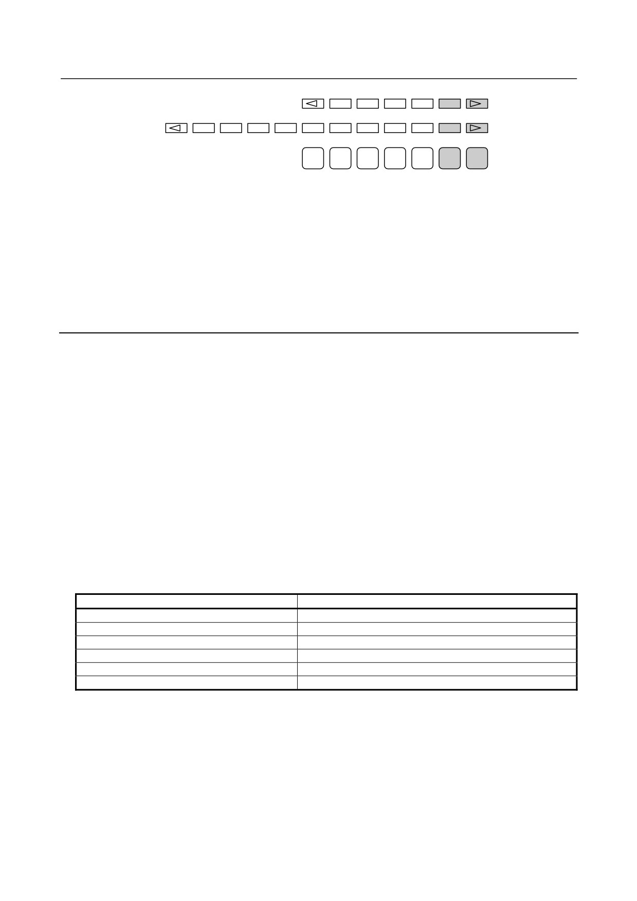
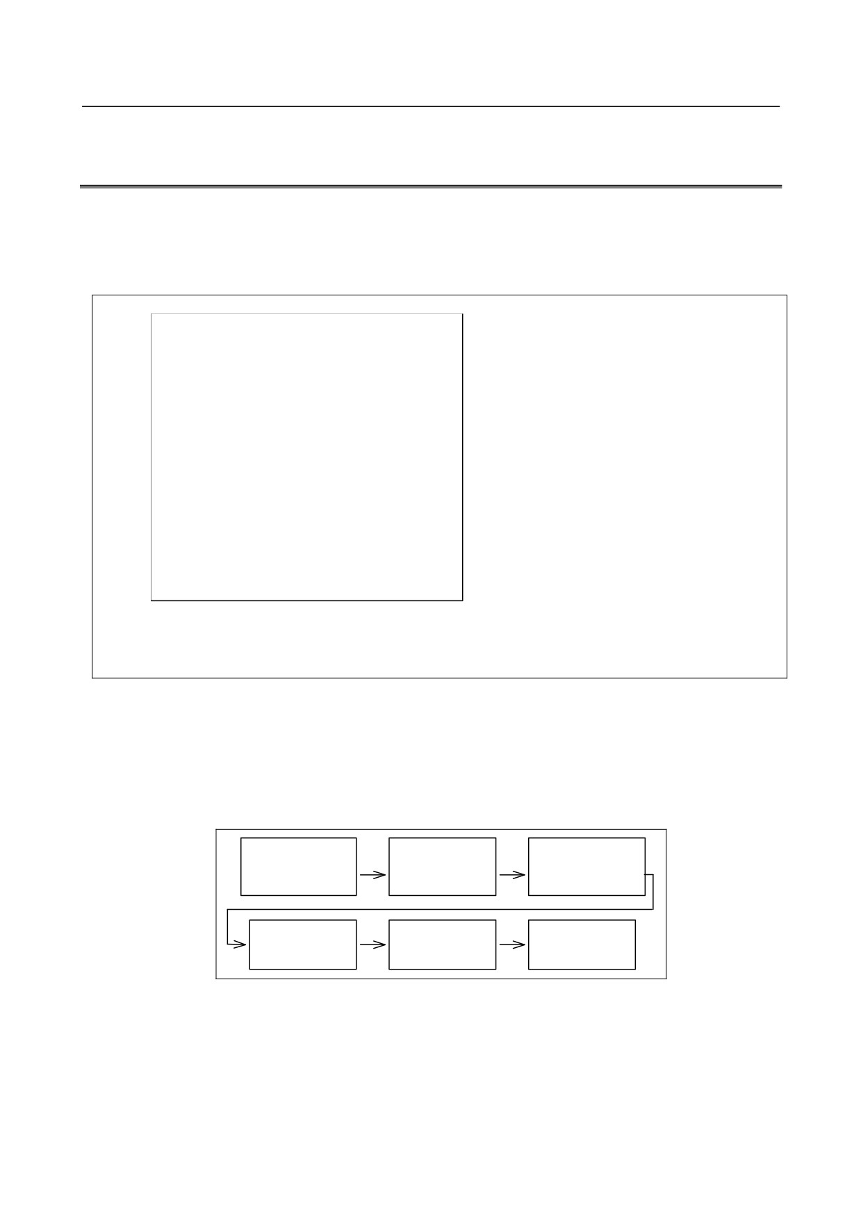
(1) In system maintenance, for example, to replace a file in ROM Operation : Turn the power on by
simultaneously pressing the two soft keys at the right end. If no soft keys are provided as with a
touch panel, use MDI numeric keys 6 and 7.
- 745 -
C.BOOT SYSTEM
APPENDIX
B-64485EN/01
1
2
3
4
5
6
7
Fig. C.1 (b)
After an FROM ID and other items are displayed on the CNC screen, releasing the key brings you to
the SYSTEM MONITOR screen.
(2) When the flash memory does not contain a file required to start the CNC
Immediately after the CNC is turned on, the boot system starts transferring files from Flash ROM to
DRAM. If, for some reason, a file required to start the CNC (NC BASIC) is not in Flash ROM or
has been destroyed, the boot system is automatically started.
C.1.3 System Files and User Files
The boot system organizes files in Flash ROM into two main groups : system files and user files. These
two file types have the following characteristics :
System files
CNC and servo control software provided by FANUC
User files
PMC sequence program (ladder), P-CODE macro program, and other user-created files
Naming convention for user files
Each of the files in flash ROM has a specific name based on its type. These file names are used by the
following items described later.
• SYSTEM DATA CHECK
• SYSTEM DATA DELETE
• SYSTEM DATA SAVE
The correspondence between the file names and their types is shown below.
Table C.1 (a)
File name
Type
PMC□
Ladder
PMCS
Ladder (for dual check safety)
M□PMCMSG
PMC message multi-language data
CEX □.□M
C Language Executor user application
CEX□○○○○
C Language Executor user data
PD□□_□□□
Macro executor user application
□: One numeric
○: One alphanumeric
- 746 -
B-64485EN/01
APPENDIX
C.BOOT SYSTEM
C.2 SCREEN CONFIGURATION AND OPERATING
PROCEDURE
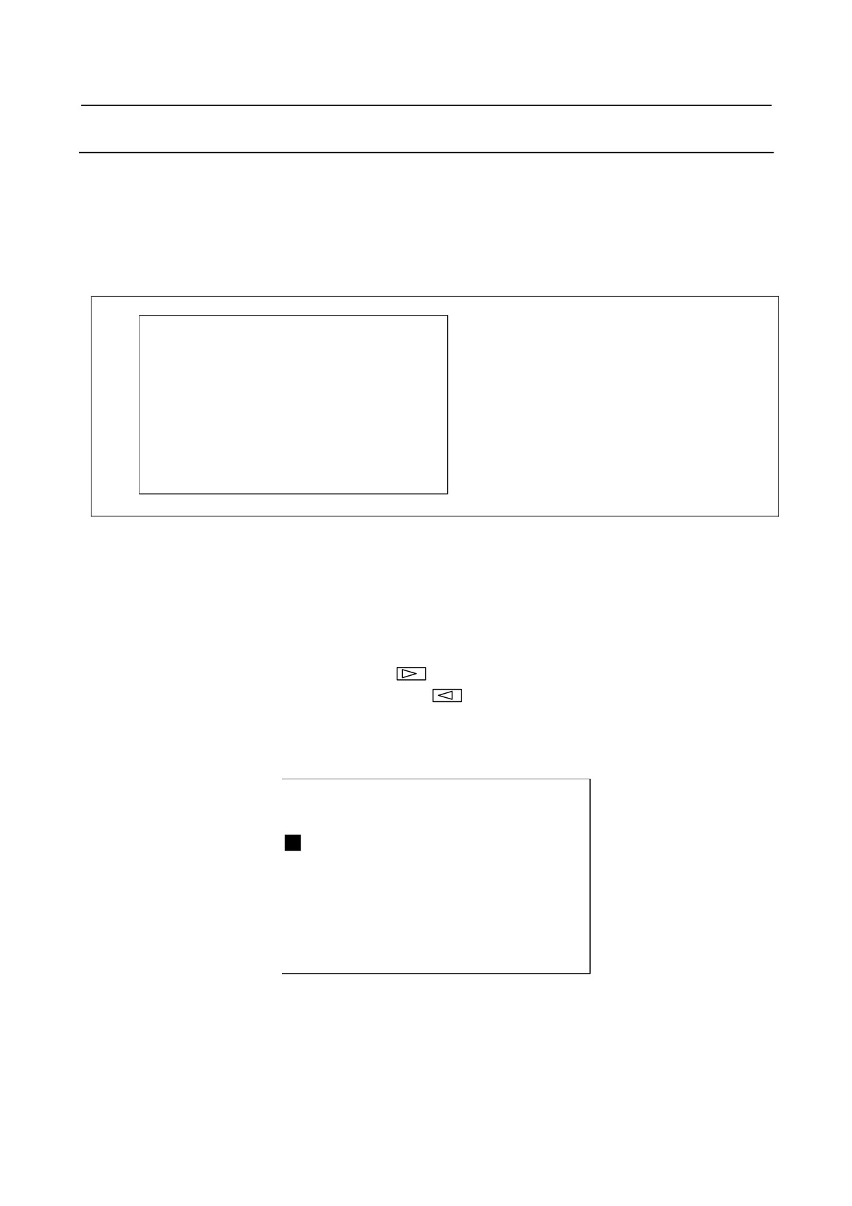
When the boot system is first started, the MAIN MENU screen is displayed. This screen is described
below :
MAIN MENU screen
(1)
SYSTEM MONITOR MAIN MENU
60W1 - 01
(1) Screen title. The series and edition of
the BOOT SYSTEM are displayed at
(2)
1.END
the right end.
(3)
2.USER DATA LOADING
(2) Function for terminating the boot
(4)
3.SYSTEM DATA LOADING
system and starting the CNC.
(5)
4.SYSTEM DATA CHECK
(3) Function for writing data to Flash
(6)
5.SYSTEM DATA DELETE
ROM.
(7)
6.SYSTEM DATA SAVE
(4) Function for writing data to Flash
(8)
7.SRAM DATA BACKUP
ROM.
(9)
8.MEMORY CARD FORMAT
(5) Function for checking the edition of a
file in ROM.
(6) Function for deleting a file from Flash
*** MESSAGE ***
ROM or Memory card.
(10)
SELECT MENU AND HIT SELECT KEY.
(7) Function for making a backup copy of
the data stored on the Memory card.
[SELECT][ YES
][ NO
][ UP
][ DOWN ]
(8) Function for backing up and restoring
the SRAM area
(9) Function for formatting a Memory
card.
(10) Simple operating instructions and
error messages are displayed.
Fig. C.2 (a)
Operating procedure
Press the [UP] or [DOWN] soft key to select the desired function. After positioning the cursor to the
desired function, press the [SELECT] soft key. Before executing a function, for a confirmation, it maybe
need to press the [YES] or [NO] soft key.
Basic operation
Position the cursor.
Select a function
Check the selection
[ UP ]
[SELECT]
[ YES ]
Execute the
Return to original
function
Select END
state
Fig. C.2 (b)
- 747 -
C.BOOT SYSTEM
APPENDIX
B-64485EN/01
C.2.1 USER DATA LOADING/SYSTEM DATA LOADING Screen
Description
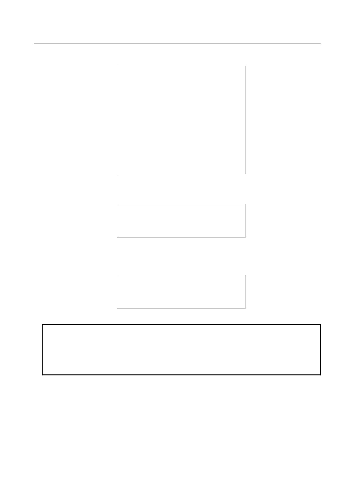
This screen is used to read a system or user file from a Memory card into Flash ROM.
The USER DATA LOADING screen is used to load ROM data from a Memory card to flash memory.
The SYSTEM DATA LOADING screen is used to check the contents of the ROM card installed in a
Memory card and then load ROM data from the Memory card to flash memory.
Screen configuration
(1)
SYSTEM DATA LOADING
(1) Screen title.
(2)
MEMORY CARD DIRECTORY
(FREE[KB]:
5123)
(2) The size of the free space of the
(3)
1 G001A_B1.MEM 1048704 2003-01-01 12:00
Memory card is displayed.
2 G001A_B2.MEM 1048704 2003-01-01 12:00
(3) A list of files in the Memory card is
(4)
3 END
displayed.
*** MESSAGE ***
(4) Returning to the MAIN MENU.
(5)
SELECT MENU AND HIT SELECT KEY.
[SELECT][ YES
][ NO
][ UP
][ DOWN ]
(5) Message
Fig. C.2 (c)
Operating procedure
(1) Position the cursor to the file to be read from the Memory card and written to Flash ROM. Then,
press the [SELECT] soft key.
-
A single page can list up to ten file names.
-
If the Memory card contains ten or more files, the remaining files are displayed on another
page.
To display the next page, press the
soft key.
To display the previous page, press the
soft key. The END option is displayed on the
last page.
(2) When you select a file from the USER DATA LOADING screen, you are prompted for
confirmation.
SYSTEM DATA LOADING
MEMORY CARD DIRECTORY
(FREE[KB]:
5123)
1 G001A_B1.MEM 1048704 2003-01-01 12:00
2 G001A_B2.MEM 1048704 2003-01-01 12:00
3 END
*** MESSAGE ***
LOADING OK ? HIT YES OR NO.
[SELECT][ YES
][ NO
][ UP
][ DOWN ]
Fig. C.2 (d)
- 748 -
B-64485EN/01
APPENDIX
C.BOOT SYSTEM
(3)
When you select a file from the SYSTEM DATA LOADING screen, a ROM data confirmation
screen is displayed for confirmation.
SYSTEM DATA CHECK & DATA LOADING
G001A_B1.MEM
1 G001 001A
2 G001 021A
3 G001 041A
4 G001 061A
5 G001 081A
6 G001 0A1A
7 G001 0C1A
8 G001 0E1A
*** MESSAGE ***
LOADING OK ? HIT YES OR NO.
[SELECT][ YES
][ NO
][ UP
][ DOWN ]
Fig. C.2 (e)
(4)
To start loading, press the [YES] soft key. To cancel, press the [NO] key.
*** MESSAGE ***
LOADING FROM MEMORY CARD xxxxxx/xxxxxx
[SELECT][ YES
][ NO
][ UP
][ DOWN ]
Fig. C.2 (f)
(5)
When loading terminates normally, the system displays the following message. Press the [SELECT]
soft key. If an error occurs, see C.3
*** MESSAGE ***
LOADING COMPLETE.
HIT SELECT KEY.
[SELECT][ YES
][ NO
][ UP
][ DOWN ]
Fig. C.2 (g)
NOTE
The CNC option parameters corresponding to the “FANUC Remote Option
System” are held in an option information file (named “OPRM INF”) in FROM.
Rewriting this file amounts to re-setting option parameters and therefore requires
authenticating them by FANUC.
Please ask FANUC to authenticate the option parameters.
- 749 -

C.BOOT SYSTEM
APPENDIX
B-64485EN/01
C.2.2 SYSTEM DATA CHECK Screen
Description
This screen is used to list files in Flash ROM or Memory card, together with the corresponding numbers
of management units in each file and the series and edition of the software.
Screen configuration
(1)
(1) Screen title.
SYSTEM DATA CHECK
(2)
(2) Select the FROM SYSTEM screen.
1.FROM SYSTEM
(3)
(3) Select the MEMORY CARD SYSTEM
2.MEMORY CARD SYSTEM
(4)
screen.
3.END
(4) Returning to the MAIN MENU.
*** MESSAGE ***
(5)
(5) Message
SELECT MENU AND HIT SELECT KEY.
[SELECT][ YES
][ NO
][ UP
][ DOWN ]
Fig. C.2 (h)
Screen configuration (FROM SYSTEM screen)
(1)
(1) Screen title.
SYSTEM DATA CHECK
FROM DIRECTORY
(2)
(2) Names of files in Flash ROM The
1 NC BAS-1(0008)
number of management units
2 NC BAS-2(0008)
constituting each file appears in
3 NC BAS-3(0008)
parentheses to the right of the filename.
4 NC BAS-4(0008)
5 DGD0SRVO(0003)
6 PS0B
(0006)
(3)
(3) Returning to the MAIN MENU.
7 END
*** MESSAGE ***
(4)
(4) Message
SELECT FILE AND HIT SELECT KEY.
[SELECT][ YES
][ NO
][ UP
][ DOWN ]
Fig. C.2 (i)
- 750 -

B-64485EN/01
APPENDIX
C.BOOT SYSTEM
Screen configuration (MEMORY CARD SYSTEM screen)
(1)
SYSTEM DATA CHECK
(1) Screen title.
(2)
MEMORY CARD DIRECTORY
(FREE[KB]:
5123)
(2) The size of the free space of the
(3)
1 G001A_B1.MEM 1048704 2003-01-01 12:00
Memory card is displayed.
2 G001A_B2.MEM 1048704 2003-01-01 12:00
(3) A list of files in the Memory card is
(4)
3 END
displayed.
(4) Returning to the MAIN MENU.
*** MESSAGE ***
(5)
SELECT FILE AND HIT SELECT KEY.
(5) Message
[SELECT][ YES
][ NO
][ UP
][ DOWN ]
Fig. C.2 (j)
Operating procedure
(1) Select either the FROM SYSTEM or MEMORY CARD SYSTEM screen.
(2) Select the file that you want to confirm (for example, "NC BAS-1 (0008)").
(3) For the selected file, the management unit numbers are listed, together with the series and editions of
the management units. After checking the listed data, select the [SELECT] soft key to return to the
file selection screen.
(1)
SYSTEM DATA CHECK
(1) Screen title.
NC BAS-1(0008)
(2)
1 G001 001A 0000
(2) The following items are displayed for
2 G001 021A 0001
each management unit:
3 G001 041A 0002
- Series
4 G001 061A 0003
- ROM number and edition
5 G001 081A 0004
- Internal management-unit number
6 G001 0A1A 0005
If a check result cannot be displayed, a
7 G001 0C1A 0006
"@" is displayed.
8 G001 0E1A 0007
*** MESSAGE ***
HIT SELECT KEY.
[SELECT][ YES
][ NO
][ UP
][ DOWN ]
Fig. C.2 (k)
Others (Parity information for the system file and user file)
The NC BAS-1, DGD0SRVO, and other system files in Flash ROM contain parity information in each
management unit. If the file name field or parity field on the check screen contains a non-ASC II
character or an "@", the Flash ROM may have been destroyed or a damaged file may have been read.
Re-read the data from the Memory card.
The PMC1, and other user files do not contain parity information in each management unit. A non-ASCII
character or an "@" may appear in the series/edition information. In this case, it does not indicate that the
file has been damaged.
- 751 -

C.BOOT SYSTEM
APPENDIX
B-64485EN/01
C.2.3 SYSTEM DATA DELETE Screen
Description
This screen is used to delete a user file from Flash ROM or Memory card.
Screen configuration
(1)
SYSTEM DATA DELETE
(1) Screen title.
(2)
1.FROM SYSTEM
(2) Select the FROM SYSTEM screen.
(3)
2.MEMORY CARD SYSTEM
(3) Select the MEMORY CARD SYSTEM
(4)
3.END
screen.
(4) Returning to the MAIN MENU.
*** MESSAGE ***
(5)
SELECT MENU AND HIT SELECT KEY.
(5) Message
[SELECT][ YES
][ NO
][ UP
][ DOWN ]
Fig. C.2 (l)
Screen configuration (FROM SYSTEM screen)
(1)
(1) Screen title.
SYSTEM DATA DELETE
FROM DIRECTORY
(2)
(2) Names of files in Flash ROM
1 NC BAS-1(0008)
The number of management units
2 NC BAS-2(0008)
constituting each file appears in
3 NC BAS-3(0008)
parentheses to the right of the filename.
4 NC BAS-4(0008)
5 DGD0SRVO(0003)
6 PS0B
(0006)
7 PMC1
(0001)
(3)
(3) Returning to the MAIN MENU.
8 END
*** MESSAGE ***
(4)
(4) Message
SELECT FILE AND HIT SELECT KEY.
[SELECT][ YES
][ NO
][ UP
][ DOWN ]
Fig. C.2 (m)
Screen configuration (MEMORY CARD SYSTEM screen)
(1)
SYSTEM DATA DELETE
(1) Screen title.
(2)
MEMORY CARD DIRECTORY
(FREE[KB]:
5123)
(2) The size of the free space of the
(3)
1 G001A_B1.MEM 1048704 2003-01-01 12:00
Memory card is displayed.
2 G001A_B2.MEM 1048704 2003-01-01 12:00
(3) A list of files in the Memory card is
(4)
3 END
displayed.
(4) Returning to the MAIN MENU.
*** MESSAGE ***
(5)
SELECT FILE AND HIT SELECT KEY.
(5) Message
[SELECT][ YES
][ NO
][ UP
][ DOWN ]
Fig. C.2 (n)
- 752 -

B-64485EN/01
APPENDIX
C.BOOT SYSTEM
Operating procedure
(1)
Select either the FROM SYSTEM or MEMORY CARD SYSTEM screen.
(2)
Select the file you want to delete.
(3)
The following message is displayed for confirmation.
*** MESSAGE ***
DELETE OK ? HIT YES OR NO.
[SELECT][ YES
][ NO
][ UP
][ DOWN ]
Fig. C.2 (o)
(4)
To start deleting, press the [YES] soft key. To cancel, press the [NO] key.
*** MESSAGE ***
EXECUTING
ADDRESS xxxx:
[SELECT][ YES
][ NO
][ UP
][ DOWN ]
Fig. C.2 (p)
(5)
When deleting terminates normally, the system displays the following message. Press the [SELECT]
soft key. If an error occurs, see C.3
*** MESSAGE ***
DELETE COMPLETE. HIT SELECT KEY.
[SELECT][ YES
][ NO
][ UP
][ DOWN ]
Fig. C.2 (q)
Others (System files and user files on SYSTEM DATA DELETE screen)
The system files are protected from accidental deletion. User files, however, are not protected. Protected
system files can be overwritten from the USER DATA LOADING / SYSTEM DATA LOADING screen.
- 753 -

C.BOOT SYSTEM
APPENDIX
B-64485EN/01
C.2.4 SYSTEM DATA SAVE Screen
Description
This screen is used to write a user file in Flash ROM to a Memory card. Only user files can be saved from
Flash ROM to a Memory card. System files cannot be saved.
Screen configuration
(1)
SYSTEM DATA SAVE
(1) Screen title.
FROM DIRECTORY
(2)
1 NC BAS-1(0008)
(2) Names of files in Flash ROM
2 NC BAS-2(0008)
The number of management units
3 NC BAS-3(0008)
constituting each file appears in
4 NC BAS-4(0008)
parentheses to the right of the filename.
5 DGD0SRVO(0003)
6 PS0B
(0006)
7 PMC1
(0001)
(3)
8 END
(3) Returning to the MAIN MENU.
*** MESSAGE ***
(4)
SELECT FILE AND HIT SELECT KEY.
(4) Message
[SELECT][ YES
][ NO
][ UP
][ DOWN ]
Fig. C.2 (r)
Operating procedure
(1)
Select the file you want to save.
(2)
The system displays the following confirmation message :
*** MESSAGE ***
SYSTEM DATA SAVE OK ? HIT YES OR NO.
[SELECT][ YES
][ NO
][ UP
][ DOWN ]
Fig. C.2 (s)
(3)
To start saving, press the [YES] key. To cancel, press [NO].
*** MESSAGE ***
STORE TO MEMORY CARD
[SELECT][ YES
][ NO
][ UP
][ DOWN ]
Fig. C.2 (t)
(4)
When saving terminates normally, the system displays the following message. Press the [SELECT]
key. The names of files written to the Memory card are listed. Check the file names by, for example,
making a note of the list.
*** MESSAGE ***
FILE SAVE COMPLETE. HIT SELECT KEY.
SAVE FILE NAME : PMC1.000
[SELECT][ YES
][ NO
][ UP
][ DOWN ]
Fig. C.2 (u)
- 754 -
B-64485EN/01
APPENDIX
C.BOOT SYSTEM
Saving ATA PROG
A file whose file name is ATA PROG contains an NC program. Even if you want to save this file, if the
boot software is of the 60W1/07 edition or later, you cannot save it on this SYSTEM DATA SAVE
screen, because it is saved together with SRAM data on the SRAM DATA UTILITY screen.
Others (System files and user files on SYSTEM DATA SAVE screen)
The SYSTEM DATA SAVE function provides a safeguard against free copying of the system files.
User files, however, are not protected.
Files saved from Flash ROM to a Memory card have the following names :
Table C.2 (b)
Header ID in Flash ROM
File name in Memory card
PMC1
→
PMC1.xxx
PD010.5M
→
PD0105M.xxx
PD011.0M
→
PD0110M.xxx
"xxx" is replaced by one of 32 numbers "000", "001", …, and "031".
For example, if you attempt to save the file "PMC1 " from Flash ROM to a Memory card, it will be saved
with a name of "PMC1.000" if no file with a name of "PMC1.000" is found on the Memory card. If,
however, that file is saved to a Memory card that already contains a file named PMC1.000, the saved file
is named PMC1.001. As files are added, the extension is incremented up to a maximum of PMC1.031.
Any no-longer used numbers in the sequence of the extension numbers are used in as sending order. If
two or more files having identical names but different extension numbers are normally saved to the
Memory card, check the file names displayed subsequently.
C.2.5 SRAM DATA UTILITY Screen
Description
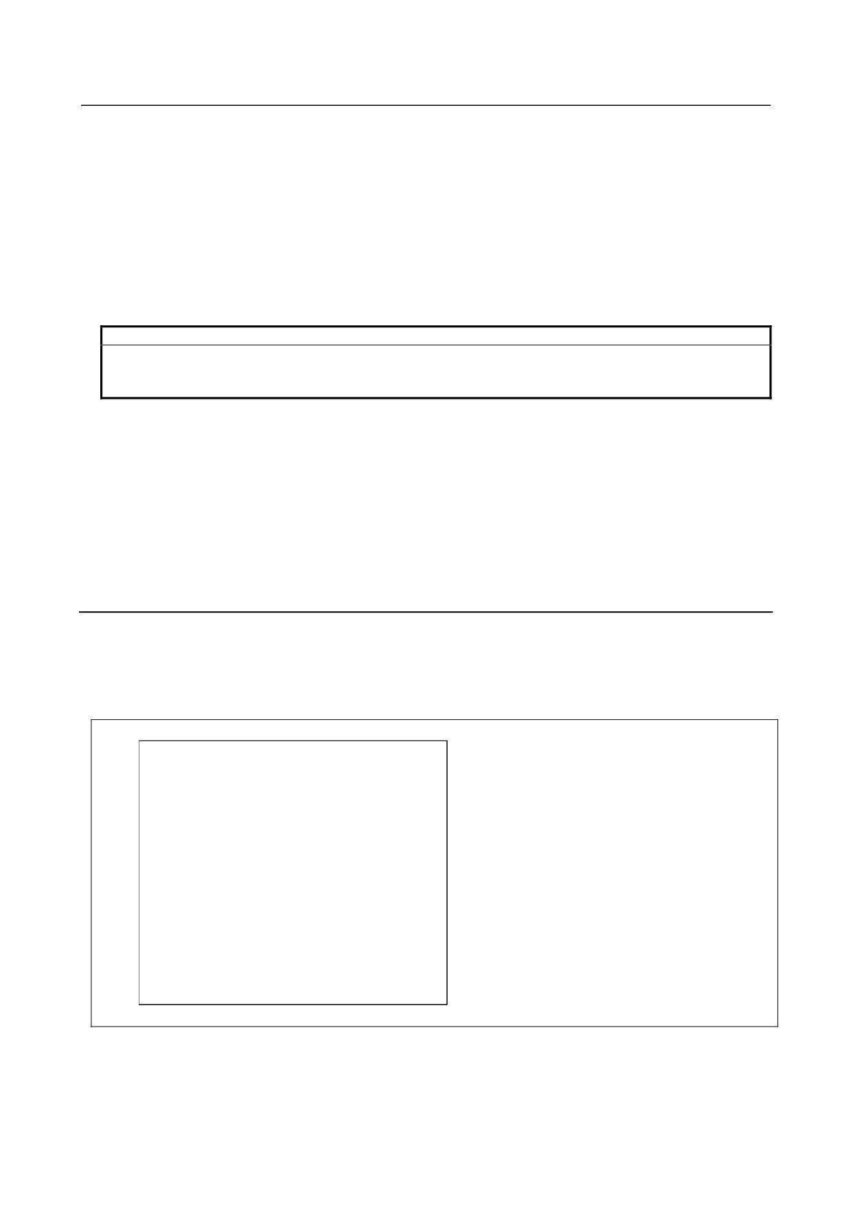
This screen is used to collectively save and restore parameters, programs, and other data, retained after
the CNC power in SRAM is turned off, to and from a Memory card.
Screen configuration
(1)
SRAM DATA UTILITY
(1) Screen title.
(2)
1.SRAM BACKUP
( CNC -> MEMORY CARD )
(2) Menu
2.RESTORE SRAM ( MEMORY CARD -> CNC )
(3)
3.END
(3) Returning to the MAIN MENU.
(4)
SRAM + ATA PROG FILE : (4MB)
(4) The SRAM file size is displayed.
(Displayed after a processing option
is selected.)
SRAM_BAK.001
(5)
(5) The name of the file currently being
saved or loaded is displayed. (Displayed
*** MESSAGE ***
after a processing option is selected.)
SET MEMORY CARD NO.001
ARE YOU SURE ? HIT YES OR NO.
[SELECT][ YES
][ NO
][ UP
][ DOWN ]
Fig. C.2 (v)
Operating procedure (Backing up data)
(1) Select "1.SRAM BACKUP" The following confirmation message is displayed. To start backup,
press the [YES] soft key.
- 755 -

C.BOOT SYSTEM
APPENDIX
B-64485EN/01
(2) If the data cannot be saved entirely onto a single Memory card, a message such as that shown below
is displayed. With the power still on, insert the second Memory card and press the [YES] key. Press
the [NO] key to cancel saving.
*** MESSAGE ***
SET MEMORY CARD NO.002
ARE YOU SURE ? HIT YES OR NO.
[SELECT][ YES
][ NO
][ UP
][ DOWN ]
Fig. C.2 (w)
(3) In this way, you can divide SRAM data onto a maximum of 999 Memory card for backup.
(4) Upon the termination of backup, the system displays the following message. Press the [SELECT]
soft key.
*** MESSAGE ***
SRAM BACKUP COMPLETE. HIT SELECT KEY.
[SELECT][ YES
][ NO
][ UP
][ DOWN ]
Fig. C.2 (x)
Operating procedure (Restoring the data)
(1)
Select "2.RESTORE SRAM" The following confirmation message is displayed. To start restoration,
press the [YES] soft key.
(2)
A message such as that shown below is displayed. Insert the first Memory card containing
SRAMBACK.001 and press the [YES] key. Press the [NO] key to cancel restoration.
*** MESSAGE ***
SET MEMORY CARD INCLUDING SRAMBAK.001
ARE YOU SURE ? HIT YES OR NO.
[SELECT][ YES
][ NO
][ UP
][ DOWN ]
Fig. C.2 (y)
(3)
If another Memory card is required, a message such as that shown below is displayed. With the
power still on, insert the second Memory card and press the [YES] key. Press the [NO] key to cancel
restoration.
*** MESSAGE ***
SET MEMORY CARD INCLUDING SRAMBAK.002
ARE YOU SURE ? HIT YES OR NO.
[SELECT][ YES
][ NO
][ UP
][ DOWN ]
Fig. C.2 (z)
(4)
Replace the second card with another, if required. Repeat this step until backing up all data.
(5)
Upon the termination of restoration, the system displays the following message. Press the [SELECT]
soft key.
*** MESSAGE ***
SRAM RESTORE COMPLETE. HIT SELECT KEY.
[SELECT][ YES
][ NO
][ UP
][ DOWN ]
Fig. C.2 (aa)
- 756 -

B-64485EN/01
APPENDIX
C.BOOT SYSTEM
CAUTION
1
Backup files will be created with a file name of SRAM_BAK.xxx, where xxx is
replaced with a number between 001 and 999 sequentially.
On the first Memory card, a backup file is created with a name of
SRAM_BAK.001. If all data is not contained on the single card, a backup file
containing the excess data is created with a name of SRAM_BAK.002 on the
second Memory card.
In this way, you can divide data onto a maximum of 999 Memory cards for
saving.
2
Check that the Memory card used for backup does not contain a file with a
name of SRAM_BAK.xxx before performing a BACKUP operation. You can
check a list of file names on a Memory card by using the SYSTEM DATA
LOADING function.
3
The Memory card used for backup needs to be formatted in FAT16.
4
The contents and name of a file to be backed up vary depending on the version
of the boot software used.
•
60W1/06 and earlier versions
Contents of file
: SRAM data
File name
: SRAMBAK.xxx
•
60W1/07 and later versions
Contents of file
: SRAM data, NC programs (ATA PROG to be saved in
flash ROM)
File name
: SRAM_BAK.xxx
It is also possible to restore data by using software of a version later than one
used to back it up.
C.2.6 MEMORY CARD FORMAT Screen
Description
This function is used to format a Memory card. Memory cards must be formatted before they can be used
for the first time or before they can be re-used after their data has been destroyed or lost because of, for
example, battery failure.
Operating procedure
(1) From the SYSTEM MONITOR MAIN MENU screen, select "8.MEMORY CARD FORMAT."
(2) The system displays the following confirmation message. Press the [YES] key.
*** MESSAGE ***
MEMORY CARD FORMAT OK ? HIT YES OR NO.
[SELECT][ YES
][ NO
][ UP
][ DOWN ]
Fig. C.2 (bb)
(3) The system displays the following message asking whether to delete all data on the Memory card.
To format the Memory card, press the [YES] key.
*** MESSAGE ***
MEMORY CARD FORMAT OK ? HIT YES OR NO.
ALL DATA IN THE MEMORY CARD IS LOST.
[SELECT][ YES
][ NO
][ UP
][ DOWN ]
Fig. C.2 (cc)
- 757 -
C.BOOT SYSTEM
APPENDIX
B-64485EN/01
(4) The system displays the following message during formatting :
*** MESSAGE ***
FORMATTING MEMORY CARD.
[SELECT][ YES
][ NO
][ UP
][ DOWN ]
Fig. C.2 (dd)
(5) When a card has been formatted normally, the system display the following message. Press the
[SELECT] soft key.
*** MESSAGE ***
FORMAT COMPLETE. HIT SELECT KEY.
[SELECT][ YES
][ NO
][ UP
][ DOWN ]
Fig. C.2 (ee)
C.2.7 LOAD BASIC SYSTEM
Description
The function is used to terminate the boot system and activate the CNC.
Operating procedure
From the MAIN MENU screen, select "1. END." The system displays the "ARE YOU SURE? HIT YES
OR NO" message. To terminate the boot system and activate the CNC, press the [YES] soft key. Press the
[NO] soft key, and you will be brought back to the MAIN MENU.
*** MESSAGE ***
ARE YOU SURE ? HIT YES OR NO.
[SELECT][ YES
][ NO
][ UP
][ DOWN ]
Fig. C.2 (ff)
C.2.8 Cautions
CAUTION
Bear the following cautions in mind if using boot software of the 60W1/06 edition
or later:
When restoring the following data in this system, be sure to restore a pair of
SRAM data and ATA PROG data which were backed up at the same time.
(ATA PROG data is in flash ROM.)
- Restoring SRAM data
- Restoring ATA PROG data
SRAM data and ATA PROG data are related to each other. Storing either data
would impair data consistency. (This may result in events such as destruction of
program files.)
If, for some reason, you need to restore either SRAM or ATA PROG data only,
be sure to initialize program files (perform a clear operation) before restoration.
- 758 -
B-64485EN/01
APPENDIX
C.BOOT SYSTEM
C.3 ERROR MESSAGES AND REQUIRED ACTIONS
The following table lists and explains error messages in alphabetical order.
Table C.3 (a)
Message
Description and required action
D
DEVICE ERROR (xxxx)
An attempt to write data to Flash ROM was unsuccessful.
Turn the power off and back on again. If the second
attempt also fails, the Flash ROM module may have been
damaged or destroyed. It is necessary to replace the Flash
ROM module.
F
FILE CLOSE ERROR.
Access to a Memory card failed. The Memory card’s
HIT SELECT KEY.
battery may have gone dead, the Memory card may have
been damaged electrically, or the Memory card may not be
inserted in the slot securely.
FILE DELETE ERROR.
Access to a Memory card failed. The Memory card’s
HIT SELECT KEY.
battery may have gone dead, the Memory card may have
been damaged electrically, or the Memory card may not be
inserted in the slot securely.
FILE OPEN ERROR.
Access to a Memory card failed. The Memory card’s
HIT SELECT KEY.
battery may have gone dead, the Memory card may have
been damaged electrically, or the Memory card may not be
inserted in the slot securely.
FILE READ ERROR.
Access to a Memory card failed. The Memory card’s
HIT SELECT KEY.
battery may have gone dead, the Memory card may have
been damaged electrically, or the Memory card may not be
inserted in the slot securely.
FILE SAVE ERROR.
Access to a Memory card failed. The Memory card’s
HIT SELECT KEY.
battery may have gone dead, the Memory card may have
been damaged electrically, or the Memory card may not be
inserted in the slot securely.
FLASH MEMORY NO SPACE.
There is insufficient free Flash ROM module to store the
HIT SELECT KEY.
selected file. Delete any unnecessary files from Flash
ROM. Alternatively, it is necessary to replace the Flash
ROM module with another with a larger size.
I
ILLEGAL FORMAT FILE.
The selected file cannot be read into Flash ROM. The
HIT SELECT KEY.
selected file or the header information for Flash ROM may
have been damaged or destroyed.
ILLEGAL SRAM MODULE.
The SRAM module ID is illegal. Check the drawing No. of
HIT SELECT KEY.
the SRAM module.
M
MAX EXTENSION OVER. HIT SELECT KEY.
The extension number added to a file name exceeds 031.
Either replace the Memory card or delete any unnecessary
backup files.
MEMORY CARD BATTERY ALARM.
The Memory card's battery is exhausted. Replace the
HIT SELECT KEY.
battery.
MEMORY CARD DISMOUNT ERROR.
Access to a Memory card failed. The Memory card’s
HIT SELECT KEY.
battery may have gone dead, the Memory card may have
been damaged electrically, or the Memory card may not be
inserted in the slot securely.
MEMORY CARD FORMAT ERROR
Access to a Memory card failed. The Memory card’s
battery may have gone dead, the Memory card may have
been damaged electrically, or the Memory card may not be
inserted in the slot securely.
MEMORY CARD FULL.
The Memory card is full. Delete any unnecessary files from
HIT SELECT KEY.
the Memory card. Alternatively, replace the Memory card
with another card having sufficient free space.
- 759 -
C.BOOT SYSTEM
APPENDIX
B-64485EN/01
Message
Description and required action
M
MEMORY CARD MOUNT ERROR.
The Memory card could not be accessed. Check that the
HIT SELECT KEY.
Memory card has been FAT-formatted.
MEMORY CARD NOT EXIST.
The Memory card is not inserted into its slot. Check that
HIT SELECT KEY.
the Memory card is pushed fully home.
MEMORY CARD PROTECTED. HIT SELECT
Although writing to the Memory card was selected, the
KEY.
write inhibit switch is set. Disable the write inhibit switch.
MEMORY CARD RESET ERROR.
Access to a Memory card failed. The Memory card’s
HIT SELECT KEY.
battery may have gone dead, the Memory card may have
been damaged electrically, or the Memory card may not be
inserted in the slot securely.
R
ROM PARITY ERROR:NC BASIC. HIT
NC BASIC data is not correct. Use SYSTEM DATA
SELECT.
CHECK to check that CNC system software is installed.
S
SRAM TEST ERROR (ECC)
An error was detected in the SRAM module. You can start
up the system because data has been automatically
restored. It is necessary to replace the SRAM module,
however, just in case that the data may be disarranged in
the future.
- 760 -
B-64485EN/01
APPENDIX
D.MEMORY CARD SLOT
D MEMORY CARD SLOT
Appendix D, "MEMORY CARD SLOT", consists of the following sections:
D.1 OVERVIEW
761
D.2 MEMORY CARD TYPES (FUNCTIONS)
761
D.3 HARDWARE CONFIGURATION
763
D.1 OVERVIEW
Whether a memory card slot is provided or not depends on the hardware configuration. See the Table D.1
(a):
Table D.1 (a)
Hardware configuration
Card slot on LCD unit
Card slot on control unit
Type 1
Provided
No card slot
Provided
Type 2
Provided
(This slot, however, cannot be used.)
Provided
Type 3
(when PANEL i is used)
Provided
(See NOTE given below.)
(Supplementary)
-
Types 1 to 3 indicate hardware configuration. See Section D.3.
NOTE
When the hardware configuration is type 3, software write operation and other
operations are implemented by Personal Computer functions.
D.2 MEMORY CARD TYPES (FUNCTIONS)
NOTE
No normal operation can be guaranteed for any memory cards other than those
purchased from FANUC.
Use of the compact flash card adapter in the card slot on the display unit side
When a compact flash card is inserted into a compact flash card adapter (A02B-0303-K150) (referred to
below as the CF adapter) purchased from FANUC, and then the CF adapter is inserted into the card slot
on the display unit side, the compact flash card lock function is available, the memory card interface
cover can be closed with the CF adapter inserted.
1.
Insertion
-
Set a compact flash card in the CF adapter (A02B-0303-K150).
-
Check that lock lever A is lifted, then insert the CF adapter into the memory card interface.
-
Lower lock lever A.
-
Close the memory card interface cover.
NOTE
1 For continuous operation with a CF adapter inserted, be sure to lower lock lever
A and close the memory card interface cover.
- 761 -