9/Series CNC Lathe. Operation and Programming Manual - page 29
Appendix B
Error and System Messages
Message
Description
SPINDLE IS CLAMPED
An attempt was made to program a block containing a spindle code other than an M05 while the
PAL servo clamp request flag for the spindle was set.
SPINDLE MODES INCOMPATIBLE
An attempt was made to enter virtual mode when the spindle that is used for this mode is
synchronized as the follower spindle or an attempt was made to perform end face milling during
synchronization.
SPINDLE MOTOR SPEED TOO HIGH
When using a 1326 motor as a spindle, feedback resolution combined with your configured
maximum spindle speed would return feedback counts faster than the control can reliably
decode. Either reduce the maximum configured spindle speed, or reduce the configured
feedback counts for the spindle in AMP.
SPINDLE MUST BE THE LAST SERVO
When the system is AMPed, the spindle must be assigned to the first available port after all axes
have been assigned.
SPINDLE NOT ASSIGNED
A spindle axis was AMPed, but not assigned to any process.
SPINDLE ORDER ERROR, AMP AUX. 2 SECOND
AMP order of spindles must be primary spindle, aux. spindle 2, aux. spindle 3.
SPINDLE ORDER ERROR, AMP AUX. 3 THIRD
AMP order of spindles must be primary spindle, aux. spindle 2, aux. spindle 3.
SPINDLE ORDER ERROR, AMP PRIMARY 1ST
AMP order of spindles must be primary spindle, aux. spindle 2, aux. spindle 3.
SPINDLE SYNC NOT CONFIGURED
The programmer attempted to enter synchronized spindle mode before it was configured in
AMP.
SPINDLE SYNC UNAVAILABLE THIS PROCESS
An attempt was made to enter synchronized spindle mode on a dual--process control when the
process was not yet configured for both spindles in the synchronized pair.
SQUARE ROOT OF NEGATIVE ERROR
Internal math error has occurred; contact Allen-Bradley customer support services.
SQUARE ROOT OF NEGATIVE INVALID
An attempt was made to determine the square root of a negative number using the calculator or
through a paramacro SQRT command.
STORED PASSWORD LIST TO BACKUP
This message appears after the password list has been successfully stored to the control’s
backup memory.
STORING TO BACKUP - PLEASE WAIT
This message appears whenever AMP or axis calibration data in RAM is being stored in backup
memory.
SYMBOL NAME FORMAT ERROR
Check the remote symbol and CNC symbol to make sure they exist on both remote and CNC.
Check the table of the read only or write only variables.
SYMBOL NOT FOUND
Check the remote symbol and CNC symbol to make sure they exist on both remote and CNC.
Check the table of the read only or write only variables.
SYNCHRONIZATION DEADLOCK
A synchronization code is activated and caused the activating process to wait on a process that
is already waiting.
SYNCH SPINDLES MISCONFIGURED
Causes for this could be: only one spindle (either controlling or follower) was defined in the
synchronized spindle pair, you exceeded the simple feedback ratio limitation of 10 (e.g., 11:1 or
2:13), or on a multiprocess system, one (or both) of the spindles in the synch pair is currently not
available to the process making the synchronization request.
SYNCH SPINDLES REQUIRE FEEDBACK
One or both of the spindles, configured in AMP as a member of a synchronized pair, did not
have feedback. Both spindles in a synchronized pair must be equipped with an AMP configured
feedback device.
SYNTAX ERROR (COMMA)
A missing comma or an extra comma was found in the program block.
SYSTEM DIAGNOSTIC #1
An illegal parameter was passed into a switch statement (mid-program start) in the control
software. Contact Allen-Bradley customer support services.
SYSTEM DIAGNOSTIC #2
An illegal parameter was passed into a switch statement (ASCII buffer task) in the control
software. Contact Allen-Bradley customer support services.
SYSTEM DIAGNOSTIC #3
An illegal parameter was passed into a switch statement (ASCII buffer task) in the control
software. Contact Allen-Bradley customer support services.
B-41
Appendix B
Error and System Messages
Message
Description
SYSTEM MODULE GROUND FAULT
The 1394 system module has detected a ground fault. The system generates a ground fault
when there is an imbalance in the DC bus of greater than 5A. This drive error can be caused by
incorrect wiring (verify motor and ground wiring), motor malfunction, or an axis module IGBT
malfunction.
SYSTEM MODULE OVER TEMP
The 1394 contains a thermal sensor which senses the internal ambient temperature. Causes
could be: that the cabinet ambient temperature is above rating. The machine duty cycle
requires an RMS current exceeding the continuous rating of the controller. The airflow access to
the 1394 is limited or blocked. This does not necessarily indicate a motor over temperature.
Motor over temperture sensors should be wired directly into the E-Stop string.
SYSTEM MODULE OVER VOLTAGE
The 1394 system module buss voltage exceeds the maximum operating voltage. The dc power
bus is continuously monitored. If it exceeds a preset level (810V dc), a fault is sensed and the
power supply is disabled. There are several possible causes for this error.
·an undersized shunt requirement
·a blown shunt regulator fuse
·a malfunctioning shunt regulator transistor
· the power driver board is malfunctioning and incorrectly sensing the bus voltage
· an incorrectly set CNC acc/dec rate
· an excessive input line voltage
· the system inertia is too high causing excessive energy to be returned to the power supply bus
·a vertical axis with insufficient counterbalancing is overdriving the servomotor and causing excessive
energy to be returned to the power supply bus
· an incorrect power supply is installed in your system. Make sure you are using a CNC power supply
SYSTEM MODULE PHASE LOSS
The 1394 system module has detected a loss of one of the input power phases. The
three--phase input line is monitored and a fault will be issued when a phase loss is detected.
Typical causes include, one or more input line fuses have opened, contactor malfunction, or
incorrect wiring.
SYSTEM MODULE UNDER VOLTAGE
The 1394 system module voltage does not meet the minimum operating voltage. The DC power
buss shall activate the under voltage limit when the bus drops to 275 VDC or less. It will clear at
300 Vdc. Typical causes include low voltage on the three phase input.
T
(T) WORD IN CIRCULAR MODE
An attempt was made to activate a tool length offset in a block that generates a circular move.
Tool length offsets can be activated only in linear blocks (or in non-motion blocks if AMP is so
configured).
T--WORD NOT ALLOWED WITH M06
NEXT TOOL IN T WORD was selected as the tool--change type in AMP while a T--word is
programmed in an M06 block.
TAN CIRCLE NOT IN 1ST BLOCK
When editing a program, an attempt was made to digitize an arc using {CIRCLE TANGNT} as
the first block in the program. To use this digitizing format, the control must first have a tool path
programmed to make the arc tangent.
TEMPLATE PROGRAM NOT FOUND
A transfer line quick view item was selected without the correct part program template present in
the protected directory. There are 19 transfer line cycles and there must be part program
templates QV01 thru QV19 present in the protected directory. Refer to your T-LINE-9 Quick
Start guide for details on replacing/restoring these part program templates.
THIRD SPINDLE NOT AVAILABLE
AMP configuration error; spindle 3 can be configured only on a 9/290.
THIRD SPINDLE NOT CONFIGURED
For spindle 3 to be programmable, it must be configured in AMP; a decode error.
THRDS/IN WORD FORMAT FINER THAN
The word format programmed is requesting a finer resolution than the axis word format for the
corresponding axis allows. These word formats are set in AMP.
THREAD FEEDRATE TOO LARGE
The lead is too large in threading mode. Program slower spindle speed.
THREAD LEAD ERROR
The thread lead was too large or too small. This commonly occurs when cutting a variable
thread lead and before the end of the threading pass is reached. Either the lead goes to zero
for a decreasing lead thread, or an axis speed would exceed its maximum allowable cutting
feedrate when cutting an increasing lead thread.
B-42
Appendix B
Error and System Messages
Message
Description
THREAD LEAD IS ZERO
No thread lead has been programmed in a block that calls for thread cutting. Thread lead is
programmed with either an F- or an E-word.
THREAD PULLOUT DISTANCE TOO LARGE
The programmed threading pullout distance is larger than the programmed distance of the
thread departure.
THREAD PULLOUT STOPPED AT I--PLANE
The chamfer block of a threading cycle is shortened so that the combination of pullout angle and
pullout distance does not cause the retract in axis 1 to go beyond the I--plane. The AMP pullout
angle is still used for the chamfer.
THREADING DISTANCE IS ZERO
A threading cycle has been programmed with no thread. Program an end-point or an end-point
different from the start-point.
TIME-OUT OCCURRED WHILE WAITING FOR INPUT
When downloading AMP or PAL from the ODS workstation to the control, the message OKAY
TO DOWNLOAD? (Y/N): appears on the control screen. If you do not respond within an allowed
time, this error will appear.
TIMER MUST START WITH #
You have used incorrect search string syntax in the PAL search monitor utility.
TOO MANY ( [ ) IN EXPRESSION
The control has found an unmatched number of [] in a program block or calculator operation. All
left brackets “[”must have a corresponding right bracket “]”.
TOO MANY ( ] ) IN EXPRESSION
The control has found an unmatched number of [] in a program block or calculator operation. All
right brackets “]”must have a corresponding left bracket “[”.
TOO MANY 7300 PATTERNS IN MEMORY
An attempt was made to enter a 7300 pattern into the control’s memory when the internal
cross-reference table of pattern repeat names was full. The internal cross-reference table of
pattern repeat names can only hold 20 pattern repeat names.
TOO MANY ACTIVE PROCESSES CONFIGURED
An AMP has been loaded that has too many actively configured processes for this controller
model. The 260 series and the dual lathe can have only 2 active processes.
TOO MANY AXES AMPED FOR HARDWARE
An AMP has been loaded that has too many configured axes for this controller model. The
9/440 series can have only up to 6 axes.
TOO MANY AXES PROGRAMMED
Too many axis letters were programmed in a fixed cycle block.
TOO MANY AXES SELECTED FOR DISPLAY
When using the {AXIS SELECT} softkey, you can display only 6 axes. If you attempt to display
more than 6 axes, this message is displayed.
TOO MANY CODES IN SYNCH BLOCK
Synch codes must be in a block by themselves, except for an N- or O-word. (9/260-9/290 dual
lathe only)
TOO MANY DECIMAL POINTS
A word or parameter value has been programmed with two or more decimal points.
TOO MANY DEVICES ON I/O RING
The I/O ring cannot support the number of devices that has been connected.
TOO MANY EXPRESSION NESTS
The maximum number of nested expressions is 25; for example, [P3+[P4+[P5]]] has 3
expressions nests.
TOO MANY G67’S
A G67 cancel modal paramacro code was executed when no modal paramacro was active.
This is typically caused when there are fewer nested modal paramacros than the programmer
expected.
TOO MANY I-J-K SETS
An attempt was made to define a local paramacro parameter that is greater than #33 using I,J,K,
argument sets. A maximum of 10 different I, J, K, sets may be programmed for each set of local
parameters.
TOO MANY MACRO CALLS
The maximum number of nested paramacros was reached. Only 4 paramacros can be active at
any one time.
TOO MANY MOTORS AMPED ON 1ST BOARD
The AMP parameter for the number of motors on the first servo board is larger than the number
of axes in the system.
TOO MANY NESTED (DO) COMMANDS
More than the allowable number paramacro DO loops are active at one time. A maximum of 3
nested DO loops are allowed.
TOO MANY NONMOTION BLOCKS-DEADLOCK
There were too many non-motion blocks encountered during the look-ahead for cutter
compensation or QPP. Consult Allen-Bradley customer support services.
B-43
Appendix B
Error and System Messages
Message
Description
TOO MANY NONMOTION CHAMFER/RADIUS BLOCKS
Too many non-motion blocks separate the first tool path that determines the chamfer or radius
size (programmed with a ,R or ,C) from the second tool path. A maximum number of
non-motion blocks is set in AMP by the system installer. A non-motion block is defined as any
block that does not generate axis motion in the current plane.
TOO MANY POCKETS IN ROUGHING CYCLE
A maximum of 2 pockets can exist in a roughing cycle.
TOO MANY QPP NONMOTION BLOCKS
Too many non-motion blocks separate the first and second tool paths with unknown
intersections in QuickPath Plus. A maximum number of non-motion blocks is set in AMP by the
system installer. A non-motion block is defined as any block that does not generate axis motion
in the current plane.
TOO MANY SHARED SPINDLES
Too many spindles were specified as being shared by two or more processes.
TOO MANY SPINDLES
More than one spindle is configured on the control.
TOO MANY SUBPROGRAM CALLS
The maximum number of nested sub-programs was reached. Only 4 sub-programs may be
active at any one time.
TOOL CONFIGURATION WILL NOT FIT
When assigning a custom tool in the random tool table, the number of pockets assigned to the
tool relative to the position of the selected shaft pocket will conflict with a different tool already
assigned to a pocket. If the custom tool is to be assigned as entered, it must be assigned to a
different shaft pocket, or the tool that conflicts with the custom tools location must be moved.
TOOL ENTRY EXCEEDS LIMIT
The selected tool number entered is greater than the AMP’ed maximum tool number entered by
the system installer.
TOOL GROUP DOES NOT EXIST
An attempt was made to edit a tool group in the tool life management tables that does not yet
exist in the tool directory. A group must be created by using the {TOOL DIR} softkey options.
TOOL OFFSET CHANGES NOT ALLOWED
During certain cycles, G10 tool change operations are not allowed.
TOOL OFFSET REQUIRES MOTION BLOCK
A tool offset cannot be changed in a non-motion block. A non-motion block is any block that
does not generate axis motion in the current plane.
TOOL RADIUS TOO LARGE
The programmed tool radius in a G88 or G89 pocket cycle is too large for the pocket contour. A
smaller radius tool must be used to machine out the current pocket contour.
TOOL RADIUS TOO SMALL FOR POCKET SIZE
The programmed tool radius in a G88 or G89 pocket cycle is too small for the pocket contour.
Either select a larger tool for the pocket contour or reduce the amount of material to be removed
each rough cut of the cycle.
TOP OF PROGRAM REACHED
When performing one of the program search operations, the first block in the program has been
reached.
TRAVERSE NOT ALLOWED ON :
An attempt was made to move an axis at rapid traverse before it was been homed. This only
applies to axes that have software overtravel limits.
TYPE 1 INTERRUPT INCOMPATIBLE WITH G24
This message occurs when returning from a type 1 program interrupt that previously interrupted
a G24 block. The interrupt is allowed however the return move is invalid since the axis was
previously in the G24 mode. You must manually intervene to continue program execution. We
recommend switching to a type 2 program interrupt.
U
UART PORT IS ALREADY OPEN
The requested serial communications port has already been opened. This message will appear
if an attempt is made to send data to a port that is currently being used.
UNABLE TO OPEN PROGRAM
The control cannot find the program that is requested. Make sure the program name is entered
correctly or the peripheral device has the correct programs loaded in it.
UNABLE TO OPEN THE UART PORT
A serial communication port error has occurred; retry. The conditions that can lead to this error
are unusual and generally will not exist when a second attempt is made to open the port. If this
error is generated continuously, it indicates that there may be a communications port hardware
failure.
B-44
Appendix B
Error and System Messages
Message
Description
UNABLE TO SYNCH IN CURRENT MODE
The control can not perform the request to synchronize spindles. Possible causes are:
synchronization is already active; virtual/cylindrical programming or a threading operation is
active on the primary or follower spindle when the synchronization request is made; or on a
dual--process system, one of the requesting processes cannot gain control over both spindles.
UNABLE TO WRITE TO FLASH MEMORY
If flash SIMMs appear to be installed correctly, remove and reseat SIMMs. If problem persists,
contact Allen--Bradley support service.
UNDEFINED INTERRUPT MACRO/SUBPROG
An interrupt program request was received by the control, but it cannot find the paramacro or
sub-program with the corresponding program name in the program directory. The program
name is defined in the enable block (M96) with a P-word.
UNEXPECTED DEPTH PROBE TRIP
G26 adaptive depth probe has fired unexpectedly. Either it has fired in a non-G26 block or it has
fired before the programmed G26 contact range.
UNSPECIFIED NETWORK ERROR
An error is being sent from another device that the module cannot interpret.
UNUSABLE WORDS IN ZONE BLOCK
An axis word or other data was programmed in a programmable zone block (G22, G22.1 G23,
G23.1). These G-codes must be programmed in blocks containing no other data except a block
delete /, N word, or comments.
UNRECOVERABLE ERROR
Can occur when updating flash SIMMs with new 9/Series firmware. Retry the update utility. If
problem persists, call Allen-Bradley Support Services.
V
VEL LOOP INVALID WITH DAC OUT
An attempt was made to select the position/velocity servo loop type on a 9/440HR system.
VIRTUAL AXIS NOT ALLOWED
The virtual axis can only be programmed when the control is in a virtual axis mode. You must
place the control in G16.3 mode to program a virtual axis.
VIRTUAL C NEEDS SPINDLE WITH FDBK
When the spindle is the virtual C axis in a virtual C application, it must be configured to provide
feedback to the servo module.
VIRTUAL/REAL AXIS NAME CONFLICT
The axis configured in AMP as the Virtual C axis was previously configured as a linear machine
axis.
W
WARNING - G10 OFFSETS ALTERED
This message warns that the offsets were changed by a G10 block during execution from a
mid-program start.
WARNING - PROGRAM STARTING AT BEGINNING
An active program was edited and then the editor exited. This causes the active program to
restart at the beginning of the program.
WARNING - VERIFY MODAL CODES
The MID START PROGRAM feature that activates modal codes for mid-program execution is
requesting that these generated modal codes be checked before program execution is started.
These modal codes can be checked on the G- and M-code status screens.
WARNING -- WATCHDOG JUMPER IS INSTALLED
This error indicates that the watchdog has been bypassed on the 9/Series hardware and your
system will not report watchdog errors. Call Allen-Bradley field service.
WHEEL AXIS MOTION INVALID IN G16.3/G16.4
While in the angled wheel grinding mode you have attempted to program the wheel axis directly.
Only the virtual axis and the axial axis can be programmed in angled wheel mode.
WILDCARD MUST BE AT START/END OF SYMBOL
You have used incorrect search string syntax in the PAL search monitor utility.
WORK CO-ORD CHANGES NOT ALLOWED
You have attempted to make a change to the work coordinate system at an invalid time.
Changes to the work coordinate system can not be performed when some features are active.
Disable the offending feature before attempting to change coordinate systems.
B-45
Appendix B
Error and System Messages
Message
Description
Z
Z-WORD CANNOT BE GREATER THAN R-WORD
The depth (Z-word) of a pocket formed using a G88.5 and G88.6 hemispherical pocket cycle
cannot be greater than the radius (R-word) of that pocket.
ZONE 2 PROGRAM ERROR
The next block in the program or MDI entry would cause the specified axis to enter the restricted
area of programmable zone 2.
ZONE 2 PROGRAM ERROR:
The current block in the program or MDI entry caused the specified axis to enter the restricted
area of programmable zone 2.
ZONE 3 PROGRAM ERROR
The next block in the program or MDI entry would cause the specified axis to enter or exit the
area defined as programmable zone 3.
ZONE 3 PROGRAM ERROR:
The current block in the program or MDI entry caused the specified axis to enter the restricted
area of programmable zone 3.
END OF APPENDIX
B-46
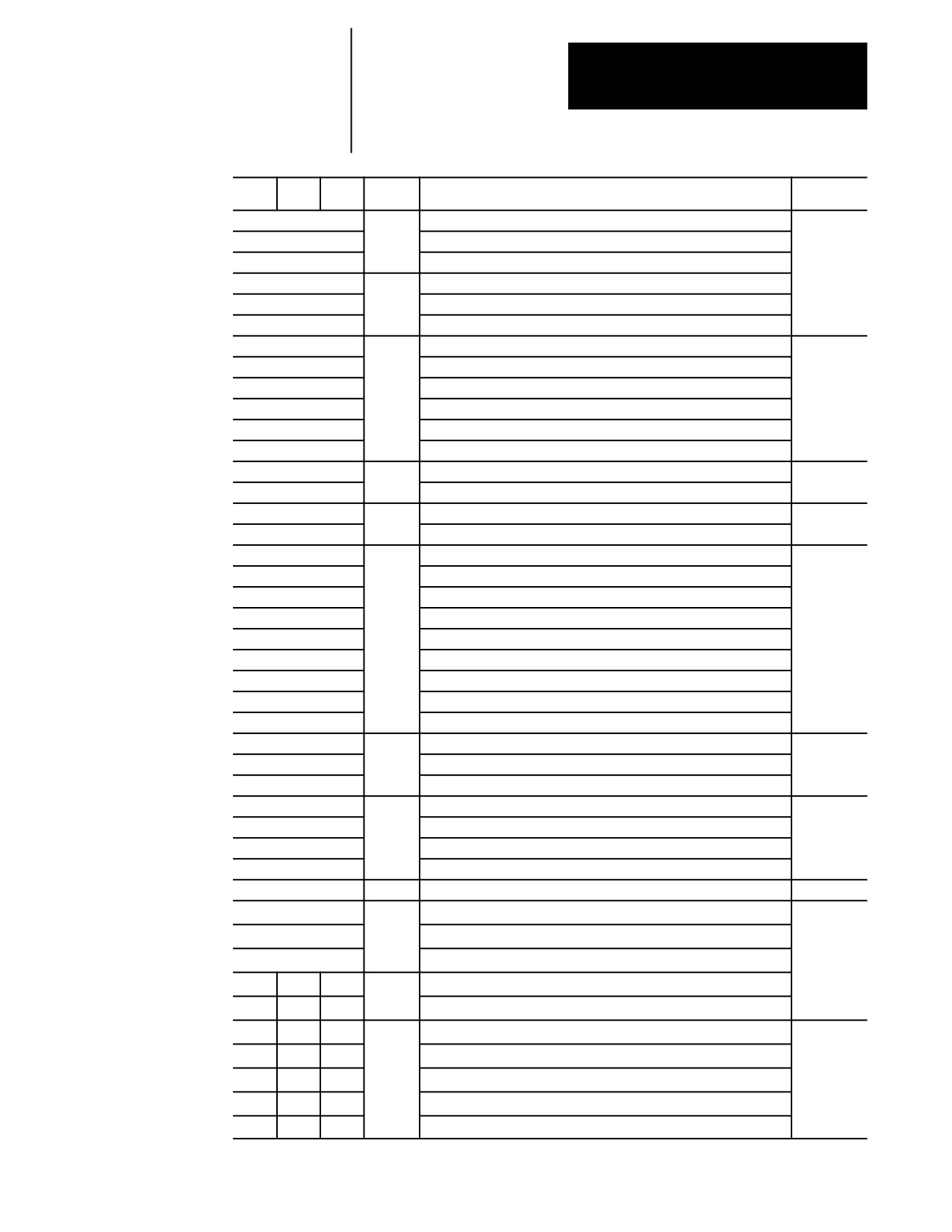
Appendix
C
G-code Tables
Appendix Overview
This appendix lists the G-codes for 9/Series turning center. This table is
presented numerically by G--code system B along with a brief description
of their use. These G-codes are discussed in detail in the sections within
this manual that refer to their specific use.
The group numbers given in the table refer to modality. Group 00 is not
modal and independent of other G-codes. The remaining G-code groups
are modal with other G-codes with the same group number. This means
programming a G-code in group 1 replaces any other active group 1
G-code, but does not affect any G-codes that are not in group 1.
Important: This manual assumes that G--code system C is used.
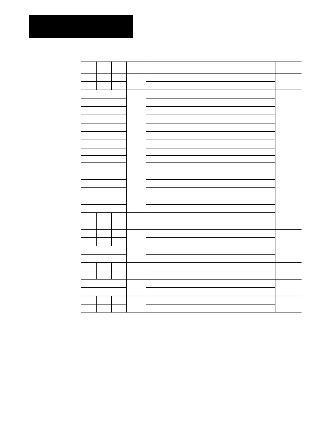
Interpreting G- codes
Table 1.A
G-code Table
A
B
C
Modal
Function
Type
G00
01
Rapid Positioning
Modal
G01
Linear Interpolation
G02
Circular Interpolation (Clockwise)
G03
Circular Interpolation (Counterclockwise)
G04
00
Dwell
Nonmodal
G05
Send Command and Wait for Return Status
(used with 9/Series Data Highway Plus Communication Module)
G05.1 -- G05.4
Send Command and Wait for Return Status
(used with 9/Series Data Highway Plus Communication Module)
G07
18
Programming Using Radius Values
Modal
G08
Programming Using Diameter Values
G09
00
Exact Stop
Nonmodal
G10L2
Setup Work Coordinate Offset Table
G10L3
Setup Tool Management Table
G10L10
Setup Tool Offset Values Geometry Table
G10L11
Setup Tool Offset Values Wear Table
G10.1
Setup Random Tool Table
G10.2L1
Communication Configuration Table
(used with 9/Series Data Highway Plus Communication Module)
G10.2L2
Output Command Table
(used with 9/Series Data Highway Plus Communication Module)
G10.2L3
Download Configuration Information
(used with 9/Series Data Highway Plus Communication Module)
G11
Setup Tool Management Table (Cancel)
C-1
Appendix C
G-code Tables
A
B
C
Modal
Function
Type
G12.1
21
Spindle 1 Controlling
Modal
G12.2
Spindle 2 Controlling
G12.3
Spindle 3 Controlling
G13
00
QuickPath Plus (Use First Intersect.)
Nonmodal
G13
QuickPath Plus (Use Second Intersect.)
G14
19
Scaling (Disable)
Modal
G14.1
Scaling (Enable)
G15
15
Virtual C (Cancel)
G16.1
Virtual C Cylindrical Interpolation
G16.2
Virtual C End Face Milling
G17
02
Plane Selection
G18
Plane Selection
G19
Plane Selection
G90
G77
G20
01
Single Pass O.D. and I.D. Roughing
G92
G78
G21
Single Pass Thread Cycle
G94
G79
G24
Single Pass Rough Facing Cycle
G22
04
Programmable Zone 2 and 3 (On)
G22.1
Programmable Zone 3 (On)
G23
Programmable Zone 2 and 3 (Off)
G23.1
Programmable Zone (Off)
G27
00
Machine Home Return Check
Nonmodal
G28
Automatic Return to Machine Home
G29
Automatic Return from Machine Home
G30
Return to Secondary home
G31
External Skip Function 1
G31.1
External Skip Function 1
G31.2
External Skip Function 2
G31.3
External Skip Function 3
G31.4
External Skip Function 4
G32
G33
G33
01
Constant Lead Thread Cutting
Modal
G34
Variable Lead Thread Cutting
G36
22
Short Block Acc/Dec (Enable)
G36.1
Short Block Acc/Dec (Disable)
G37
00
Tool Gauging Skip Function 1
Nonmodal
G37.1
Tool Gauging Skip Function 1
G37.2
Tool Gauging Skip Function 2
G37.3
Tool Gauging Skip Function 3
G37.4
Tool Gauging Skip Function 4
G39
20
Tool Tip Radius Compensation (Linear Generated Block)
Modal
G39.1
Tool Tip Radius Compensation (Circular Generated Block)
G40
07
Tool Tip Radius Compensation (Cancel)
G41
Tool Tip Radius Compensation (Left)
G42
Tool Tip Radius Compensation (Right)
C-2
Appendix C
G-code Tables
A
B
C
Modal
Function
Type
G45
23
Disable Spindle Synchronization
Modal
G46
Set Spindle Positional Synchronization
G46.1
Set Active Spindle Speed Synchronization
G47
24
Linear Acc/Dec in All Modes
G47.1
S--Curve Acc/Dec for Positioning and Exact Stop Mode
G47.9
Infinite Acc/Dec (No Acc/Dec) (AMP--selectable only)
G48
00
Reset Acc/Dec to Default AMPed Values
Non--Modal
G48.1
Acceleration Ramp for Linear Acc/Dec Mode
G48.2
Deceleration Ramp for Linear Acc/Dec Mode
G48.3
Acceceleration Ramp for S--Curve Acc/Dec Mode
G48.4
Dececeleration Ramp for S--Curve Acc/Dec Mode
G48.4
Programmable Jerk Value
G50.1
11
Programmable Mirror Image (Cancel)
Modal
G51.1
Programmable Mirror Image
G52
00
Offset Coordinate Zero Points
Nonmodal
G53
Motion in Machine Coordinate System
G54
12
Preset Work Coordinate System 1
Modal
G55
Preset Work Coordinate System 2
G56
Preset Work Coordinate System 3
G57
Preset Work Coordinate System 4
G58
Preset Work Coordinate System 5
G59
Preset Work Coordinate System 6
G59.1
Preset Work Coordinate System 7
G59.2
Preset Work Coordinate System 8
G59.3
Preset Work Coordinate System 9
G60
25
Synchronous Logic/Block Synchronization Mode
Modal
G60.1
Asynchronous Logic/Block Synchronization Mode
G60.2
Autosynchronous Logic/Block Synchronization Mode
G61
13
Exact Stop Mode
Modal
G62
Automatic Corner Override
G63
Tapping Mode
G64
Cutting Mode
G65
00
Paramacro Call
Nonmodal
G66
14
Paramacro call
Modal
G66.1
Paramacro call
G67
Paramacro call cancel
G20
G20
G70
06
Inch system selection
G21
G21
G71
Metric system selection
G70
G70
G72
00
O.D. and I.D. Finishing Cycle
Nonmodal
G71
G71
G73
O.D. and I.D. Roughing Cycle
G72
G72
G74
Rough facing cycle
G73
G73
G75
Casting/forging roughing cycle
G74
G74
G76
Face Grooving Cycle
C-3
Appendix C
G-code Tables
A
B
C
Modal
Function
Type
G75
G75
G77
O.D. and I.D. Grooving Cycle
G76
G76
G78
O.D. and I.D. Multi-Pass Threading Routine
G80
09
Cancel or end fixed cycle
Modal
G81
Drilling cycle (no dwell, rapid out)
G82
Drilling cycle (dwell, rapid out)
G83
Deep hole peck drilling cycle
G83.1
Deep hole peck drilling cycle (dwell)
G84
Right hand tapping cycle
G84.1
Left hand tapping cycle
G84.2
Right hand solid tapping cycle
G84.3
Left hand solid tapping cycle
G85
Boring cycle (no dwell, feed out)
G86
Boring cycle (spindle stop, rapid out)
G86.1
Boring cycle (spindle shift)
G87
Back boring cycle
G88
Boring cycle (spindle stop, manual out)
G89
Boring cycle (dwell, feed out)
-- --
G90
G90
03
Absolute mode
-- --
G91
G91
Incremental mode
G50
G92
G92
00
Coordinate offset using tool positions
Nonmodal
G50
G92
G92
Maximum CSS Spindle RPM
G92.1
Coordinate system offset cancel
G92.2
Cancel select offsets
G98
G94
G94
05
Feed per minute mode
Modal
G99
G95
G95
Feed per revolution mode
G96
17
CSS ON
Modal
G97
RPM Spindle Speed Mode
-- --
G98
G98
10
Initial level return drilling cycles
Modal
-- --
G99
G99
R-point level return drilling cycles
END OF APPENDIX
C-4
Appendix
D
Allen-Bradley 7300 Series CNC Tape
Compatibility
Appendix Overview
The 7300 Series CNC tape compatibility feature has been developed for
customers with an existing library of standard 7320 and 7360 CNC tapes.
This feature allows those 7300 tapes to be read and executed by the
control. If desired, these 7300 tapes can be copied into the control’s
memory to allow editing and execution, or they can be executed directly
from tape, with the exception of 7300 pattern repeat subprograms.
Important: This feature is not intended to let you to develop new 7300
part programs with the control. We strongly recommend that for new part
programs, you learn to develop them by using the control’s programming
method.
Important: S--Curve Acc/Dec mode is not available in 7300 mode.
To use the 7300 tape compatibility feature, the system installer must enable
this feature in PAL. Refer to your system installer’s documentation and the
PAL manual for details on how the 7300 Series CNC tape format feature is
activated.
G-code Compatibility
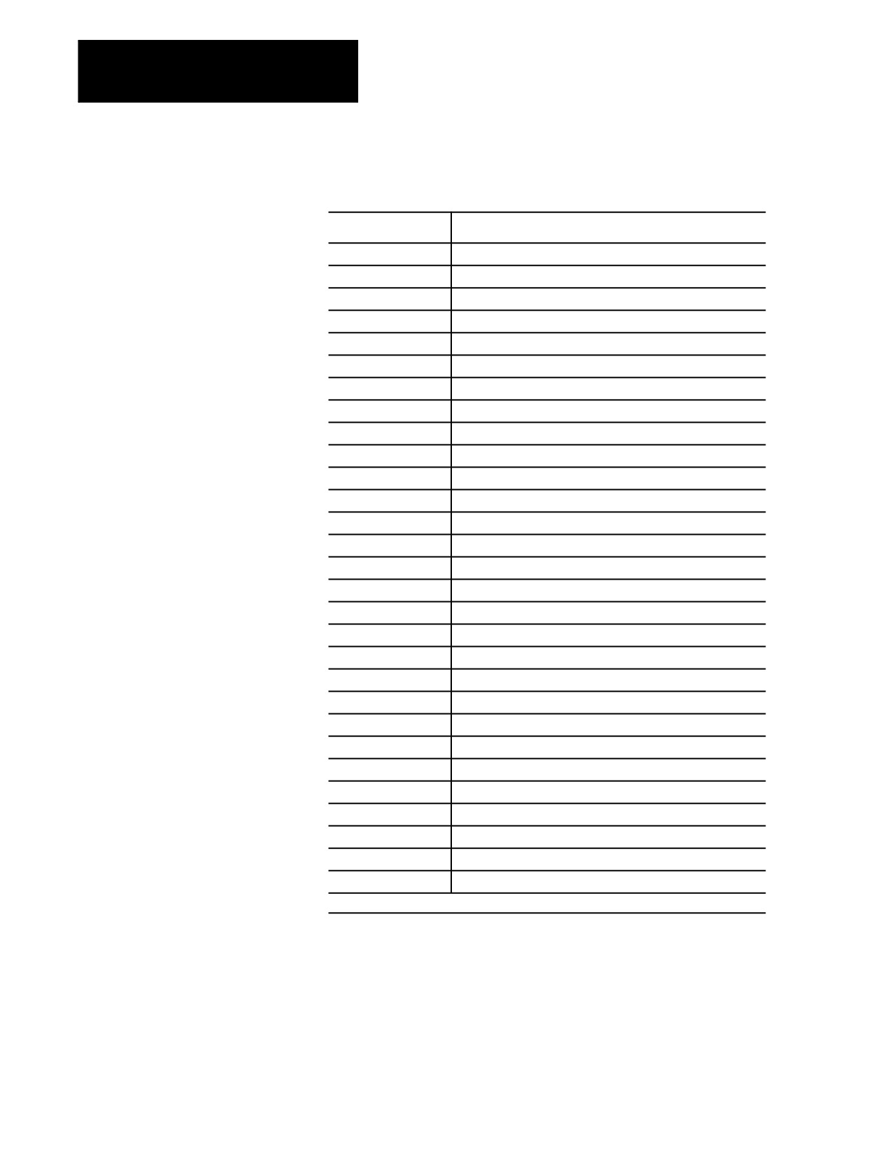
Table D.A lists all of the 7300 G-codes that the control can execute in 7300
mode. See the System 7360 Programming Manual for details on these
Considerations
G-codes and their operation.
D-1
Appendix D
Allen-Bradley
7300 Series CNC
Tape Compatibility
Table D.A
G-codes
G-code:
Function:
G00
Positioning mode
G01
Linear interpolation
G02
Circular interpolation CW
G03
Circular interpolation CCW
G04
Dwell
G21
Linear interpolation with delay
G22/G23
Circular interpolation with delay
G281
1st auto threading cycle parameters
G291
2nd auto threading cycle parameters and execute code
G33
Thread cutting (I and K)
G34
Variable lead threading, increasing
G35
Variable lead threading, decreasing
G40
Tool tip radius compensation off
G41
Tool tip radius compensation left
G42
Tool tip radius compensation right
G70
Inch mode
G71
Metric mode
G74
Full circle programming off
G75
Full circle programming, EIA standard
G76
Full circle programming, AB standard
G90
Absolute programming mode
G91
Incremental programming mode
G92
Insert absolute preset
G93
V/D feedrate coding
G94
Feed per minute
G95
Feed per revolution
G96
Constant surface speed on (spindle in rpm mode)
G97
Cancel constant surface speed off (spindle in rpm mode)
G99
Cancel G92
1 These are optional features included with the standard
7360 Lathe G-codes.
D-2
Appendix D
Allen-Bradley 7300 Series CNC
Tape Compatibility
G28 and G29 Automatic Thread Cutting or Roughing Cycle
G28 and G29 are not standard 7300s Lathe G-codes, but have been
provided to enable automatic thread cutting or roughing. Both G28 and
G29 are used for the Automatic Thread Cutting cycle. This Automatic
Thread Cutting feature simplifies part programming of multiple-pass
thread cutting operations for straight or tapered constant-lead threads.
With this feature, an entire multi-pass thread cutting operation is
programmed in only two data blocks. These blocks contain parameters
that specify the following characteristics of the thread:
final thread depth
thread depth of first pass
infeed path
infeed feedrate
thread length
thread lead
pullout-in-lead distance
return pass clearance
return pass feedrate
Important: G28 and G29 are programmed consecutively within the part
program. The first automatic threading block must contain a G28 code; the
next block must contain a G29 code. An error occurs if you program these
G-codes separately.
When a G33 code is programmed in a G29 data block, it establishes
Thread Cutting mode for the automatic multi-pass thread cutting cycle.
When a G01 is programmed with a G29 data block, the G01 establishes the
Linear Interpolation mode for automatic multi-pass roughing cycles.
Either a G33 or a G01 has to be accompanied by a G29 data block in order
to perform any of the cycles mentioned above.
Important: The G01 code programmed in the G29 block is not modal; the
control automatically cancels the linear interpolation mode after a
multi-pass roughing cycle is completed.
D-3
Appendix D
Allen-Bradley
7300 Series CNC
Tape Compatibility
The format for the G28 block is:
G28__D__X__Z__F
Where:
Specifies:
D
final threading depth or roughing depth. For Absolute Programming mode (G90), this
parameter is programmed as an X axis position. For Incremental Programming mode
(G91), this parameter is programmed as a distance measured parallel to the X axis from
the initial work surface.
X
depth of first thread cutting pass or first roughing pass. For Absolute Programming
mode, the initial depth is programmed as an X axis position. For Incremental
Programming mode, this initial depth is programmed as a distance measured parallel to
the X axis from the initial work surface.
Z
the distance between the starting point and the infeed endpoint on the Z axis. Not
programming a Z or programming a Z that does not create any axis motion results in a
plunge infeed. A plunge infeed moves the tool directly into the part with no Z component
in the move.
Programming a Z that is different than the starting point Z location generates a tapered
infeed. For threads that are cut with tapered infeed, the tool is fed into the part at an
angle comprised of both X and Z motions. The angle is determined by the linear
intersection of the start point and the endpoint. The endpoint is determined by this
parameter on Z axis and final depth is determined by D.
F
feedrate of the plunge or compound infeed. The infeed rate is programmed in the
units/inches per minute (IPM) in the inch mode, or millimeters/minute (MMPM) in the
Metric mode.
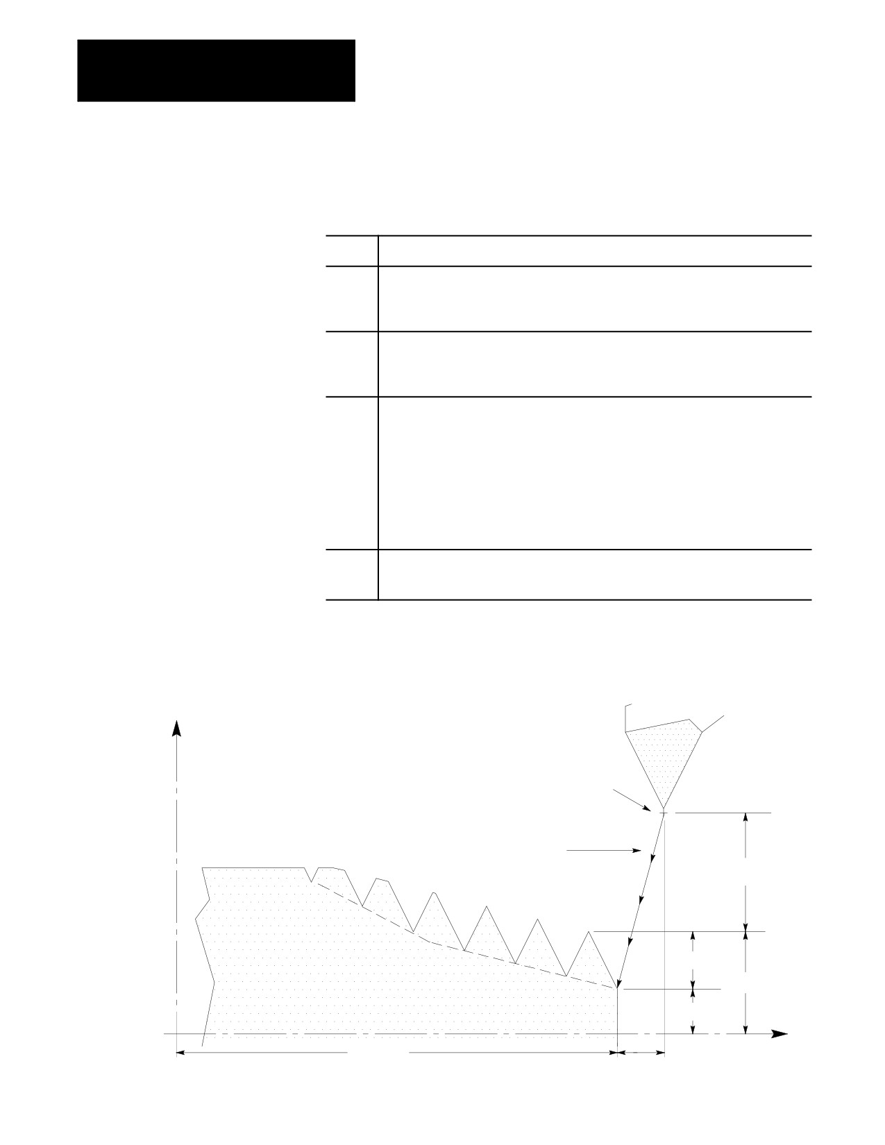
Figure D.1 illustrates these parameters.
Figure D.1
G28 Multi-pass Thread Cutting Parameters
(Absolute/Incremental Programming Mode)
X
Starting point
1st pass
Tapered infeed
2nd pass
X inc.
3rd pass
D inc.
X abs.
D abs.
Z
Z inc.
Z abs.
D-4
Appendix D
Allen-Bradley 7300 Series CNC
Tape Compatibility
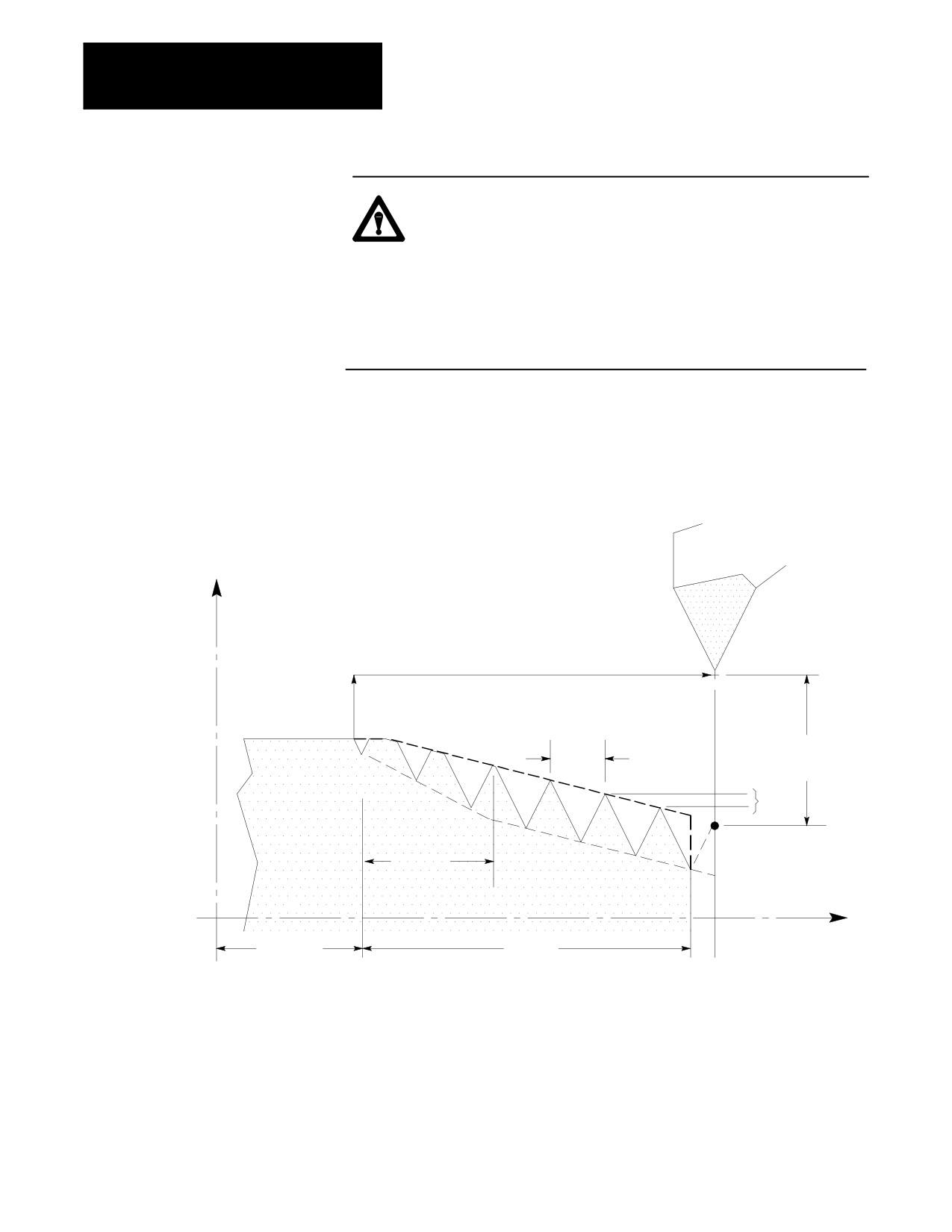
The format for the G29 block is:
G29__D__K__I__Z__L__F
Where:
Specifies:
D
return pass clearance, which is the distance between the initial work surface and the
starting point. D value must always be programmed as an incremental distance,
regardless of the current operating mode.
K
thread lead, which is the distance the thread cutting tool is to move along the Z axis per
revolution of the spindle. The thread lead is always programmed in units of inches per
revolution (IPR) in the Inch format mode (G70), or millimeters per revolution (MMPR) in
the Metric format mode (G71).
Does not need to be programmed for roughing cycle.
I
thread lead for a tapered thread, which is the distance and direction the thread cutting
tool is to move along the X axis per revolution of the spindle. The thread lead is always
programmed in units of inches per revolution (IPR) in the Inch format mode (G70), or
millimeters per revolution (MMPR) in the Metric format mode (G71). The I-word
determines the angle of a tapered thread. If the angle is known, I-word can be
calculated with the following formulas:
I-word = K-word * Tan0
Assign a value to I only if cutting tapered threads (I ¹ 0).
Length of the roughing pass for Z axis roughing cycle, I is the distance along the X axis.
Does not need to be programmed for single axis roughing.
Z
length of the thread. For Absolute Programming mode, the thread length is programmed
as the Z axis position of the end of the thread. For Incremental Programming mode, the
thread length is programmed as a distance measured parallel to the Z axis from the
infeed endpoint to the end of the thread.
Length of the roughing pass for roughing cycle, which is the distance measured parallel
to the Z axis.
L
pullout distance, which is the distance from the programmed end of the thread to the
point at which the thread cutting tool is to start pulling out from the workpiece. This
distance is measured parallel to the Z axis. If no L-word is programmed, then the tool
does not pull out until it reaches the programmed end of the thread. L-word must always
be programmed as an incremental distance, even in the Absolute Programming mode.
F
feedrate of the return path, which is the rate at which the tool moves away from the part
and returns to the start-point of the cycle for the next infeed. The infeed rate is always
programmed in units/inches per minute (IPM) in the Inch mode, or millimeters/minute
(MMPM) in the Metric mode. If no F-word is programmed in the G29 block, the last
programmed feedrate before the G28 block is used.
D-5
Appendix D
Allen-Bradley
7300 Series CNC
Tape Compatibility
CAUTION: The feedrate of any thread cutting pass is
lead-limited to 100 inches per minute (IPM). If the values of
the programmed thread lead and the currently active spindle
speed generate a feedrate that exceeds 100 IPM, the control
automatically reduces the value of the programmed thread lead
to limit the thread cutting feedrate at 100 IPM. The lead of the
resulting thread, therefore, is less than the programmed thread
lead.
Figure D.2 illustrates these parameters.
Figure D.2
G29 Multi-pass Thread Cutting Parameters
(Absolute/Increment Programming Mode)
X
K inc.
D inc.
I inc.
L inc.
Z
Z abs.
Z inc.
D-6
Appendix D
Allen-Bradley 7300 Series CNC
Tape Compatibility
M-code Compatibility
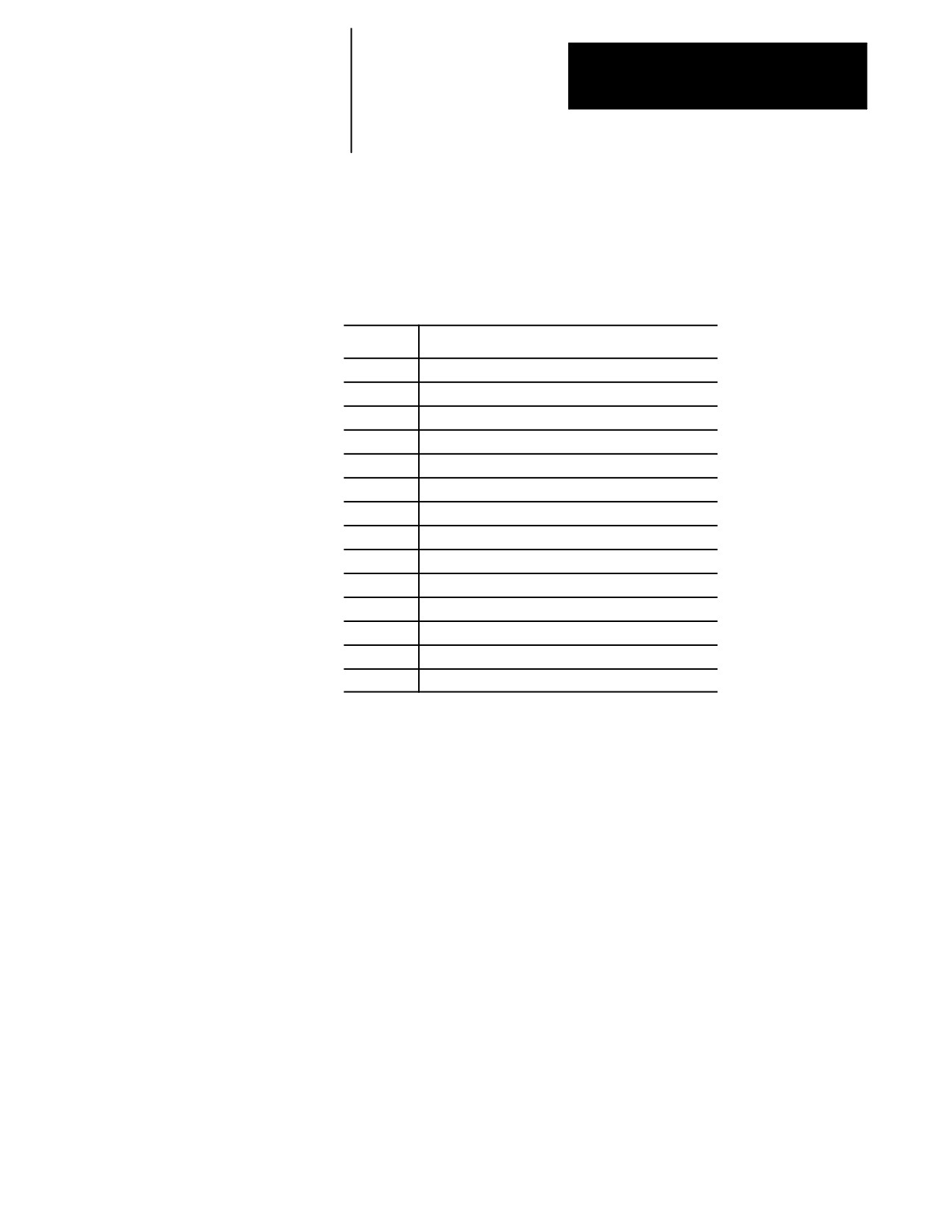
Table D.B lists all of the 7300 M-codes that the control can execute in
7300 mode. See the System 7360 Programming Manual for details on
Considerations
these M-codes and their operation.
Table D.B
M-codes
M-code:
Function:
M00
Program stop
M01
Optional program stop
M02
End of program
M03
Spindle on, CW
M04
Spindle on, CCW
M05
Spindle off
M07
Mist coolant on
M08
Flood coolant on
M09
Coolant off
M30
End of program, rewind
M48
Feedrate override, spindle override, normal
M49
Feedrate override, spindle override, bypass to 100%
M80
Constant surface speed, normal
M81
Constant surface speed, inhibit
D-7
Appendix D
Allen-Bradley
7300 Series CNC
Tape Compatibility
Offset Compatibility
Tool Length Offset
Considerations
When the control is in 7300 mode, tool length offsets are activated in the
same manner as on the 7300. The control supports 1- through 4-digit
T-words, and through AMP configuration, you have the flexibility of
specifying how the control activates offsets.
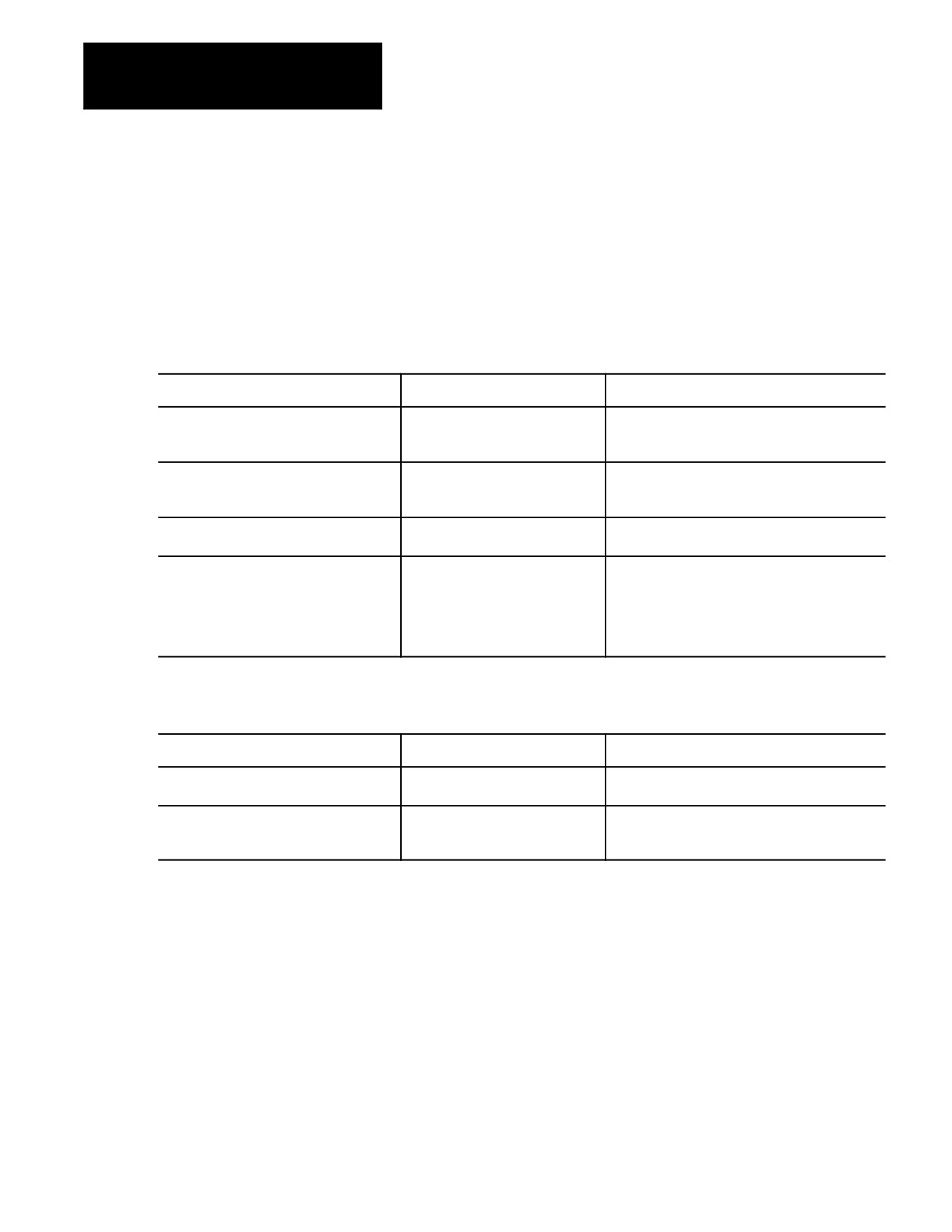
We recommend that you use this set-up when running your control in 7300
mode:
Set This Tool Length Offset Parameter:
To:
Explanation:
Tool Geometry Mode (AMP [202]):
immediate shift/immediate move
once the offset is programmed, the geometry offset
is activated immediately and the coordinate system
gets shifted immediately.
Tool Wear Mode (AMP [203]):
immediate shift/immediate move
once the offset is programmed, the wear offset is
activated immediately and the coordinate system
gets shifted immediately.
Tool Offset Cancel (AMP [204]):
cancel geometry & wear
both the geometry and wear offsets are cancelled
when the active offset is cancelled.
T-code Format (AMP [205]):
2-digit geometry & wear
The 2 right-most digits are used for geometry &
wear; and the leftover are used for tool number.
Example: T10 activates geometry offset 10 and
wear offset 10 on tool number 0.
Example: T915 activates geometry offset 15 and
wear offset 15 on tool number 9.
If the Tool Life Management option is present, set the following AMP
parameters for 7300 compatibility:
Set This Tool Length Offset Parameter:
To:
Explanation:
Tool Number/Group Boundary (AMP [131]):
9799
specify the division between ordinary tool numbers
and tool life groups.
T-word Programming Method (AMP [132]):
next Tool in T-word
for this method, the T-word to be activated is
programmed in a block that does not contain an
M06.
For systems with the Tool Life Management option, the T-word is limited
to four digits in the range of 1 to 9799.
Refer to the AMP manual for details on any of the above AMP parameters.
Important: When 7300 mode is active on the control, automatic tool
changing requires the proper PAL interface and may require changing the
AMP parameters described above. The random tool feature of the control
is also available to interface with special tool changers.
D-8
Appendix D
Allen-Bradley 7300 Series CNC
Tape Compatibility
The control has two offset tables: geometry and wear table. The sum from
these two tables is used to generate tool length data when the tool offset
number is programmed. When in 7300 mode, the active offset is also
computed as the sum of the geometry and wear offsets. Refer to chapter 3
for details.
When changing from inch to metric (or vice versa) in 7300 mode, the
control does automatic conversion on tool offset values. The 7300 did
not provide this automatic conversion and, instead, required the operator to
re-enter tool offsets.
A T-word cannot be programmed in circular interpolation mode (G02 or
G03).
Important: The control allows the Power-Turn-On (PTO) mode of the
control to be specified in AMP with respect to inch/metric (G70/G71) and
absolute/incremental (G90/G91) etc. For 7300 tape compatibility, these
parameters may need to be modified if a certain PTO mode is expected.
Refer to the AMP manual for details.
Additional Feature
In this section, we describe how to copy a 7300 tape to the control. This
process involves these steps:
Compatibility
Considerations
store a 7300 part program and pattern repeat into the control
execute the 7300 part program and patten repeat
Storing 7300 Part Programs
A 7300 tape can be stored in control memory by using the COPY
PRGRAM softkey function. While reading the tape to the control, any TN
code, which defined the program name for 7300s, is interpreted as a
comment block; this means a new program name must be entered. The
control prompts you to enter a program name for each part program or
pattern repeat stored. The name given to the program must adhere to the
format of control program names.
Important: When storing a pattern, the pattern name entered here must be
a 1-to 5-digit numeric prefixed with the letter O; for example, O10005.
Refer to section 11.5.9 for information on valid subprogram names.
At this time, the control creates an internal cross-reference table for all
pattern repeat names. The cross-reference table is generated so that any
blocks that call pattern repeat do not need to be rewritten with the new
program name. Refer to the section on Pattern Repeat for details.
You can not copy pattern repeat programs from memory to memory.
Doing so does not create the necessary cross-reference table.
D-9
Appendix D
Allen-Bradley
7300 Series CNC
Tape Compatibility
Pattern Repeat
A pattern repeat is a series of blocks of information repeated a specified
number of times for a specified function. A pattern repeat is called in 7300
mode with the following format:
(CP, name, r)#
where:
Name:
Indicates:
CP
a pattern repeat is called.
name
the pattern blocks being called (part program name).
r
the number of times the pattern blocks get executed.
#
end of block.
You can store patterns in the control by using the COPY PRGRAM softkey
function. The control requires that a new program name be entered for
each pattern. The control automatically creates an internal cross-reference
table of 7300 pattern names. This cross-reference table consists of the
subprogram file name called by the main program, and the new file name
entered for the pattern repeat. The control takes the first program start
code from the tape and corresponds it to the file name you have just
entered for the pattern repeat; this way, you do not need to modify your
main program so that it still calls the correct pattern. This cross reference
table is maintained by the control, and it is transparent to you. For
example:
Important: The patterns called must be saved as independent part
programs and copied into control memory from a peripheral device. You
can not create new pattern repeat programs online. A maximum of 20
patterns can be copied into the controls memory.
You have a 7300 part program that has a pattern named
BL-M008-001. When you stored the part program to the control, the
control prompted you for a name; you entered O00001. The part
program and the pattern are now stored in the memory. At this point,
the control searches for the program start code on the tape and takes
the code and matches it with O00001. When this pattern name is
called, the control automatically searches the cross-reference table
for BL-M008-001 and executes O00001.
The (DP) block is saved in memory as part of the program, and it is treated
as a comment block during the execution of the part program.
D-10
Appendix D
Allen-Bradley 7300 Series CNC
Tape Compatibility
Executing 7300 Part Programs
The system installer has to write PAL program for the control to execute in
7300 tape compatibility mode. Refer to the PAL manual for details.
The control allows the Power-Turn-On mode (PTO) of the control to be
specified in AMP with respect to inch/metric (G70/G71) mode and
absolute/incremental (G90/G91) programming mode. For 7300 tape
compatibility, we recommend that you select G70 and G90 for PTO mode.
When 7300 tape compatibility mode is enabled, the following modal
conditions are automatically established and cannot be selected in AMP:
G36.1 Short block Acc/Dec enabled
G39.1 Tool Tip Radius Compensation Circular Transition
Important: When programming a G00 in 7300 mode, the 9/Series control
uses the <RAPID OVERRIDE> switch to override the rapid feedrate. This
applies to any programmed rapid move including moves generated by the
fixed cycles or pattern repeats. The operation of the <RAPID
OVERRIDE> switch is very PAL dependent, and can be alter by your
system installer’s PAL logic. See your system installer documentation for
details.
The part program can be executed from tape or control memory. If a 7300
program makes pattern calls, the patterns must reside in control memory.
The control attains compatible pattern repeat functionality by using an
M98 subprogram call. When the control executes the 7300 pattern repeat
call, it makes the following substitutes:
Control Uses:
To substitute 7300’s:
To Indicate:
M98
CP
a pattern repeat is called.
Pnnnnn
name
the pattern blocks being called (part program name).
Lmmm
r
the number of times the pattern blocks get executed.
#
#
end of block.
Important: In order for the control to properly execute a M98 subprogram
call, the blocks called by the pattern repeat must be stored under a program
name starting with the letter O, followed by one through five numeric
characters. Refer to section 11.5.9 for information on valid file names.
D-11
Appendix D
Allen-Bradley
7300 Series CNC
Tape Compatibility
The main program, which has the pattern repeat call block “(CP, name, r),”
can be executed from tape or from the control memory. However, if you
want to make minor editing to your main program, you must copy the
program into the control memory. Refer to section 10.2, “Inputting Part
Programs,” for details on how to copy a program from tape.
Important: To execute a program from tape, the tape must be positioned
at the start of the main program.
For more information on how subprograms are executed in the control,
refer to chapter 10, “Subprogram Call (M98).”
9/Series G-codes Applicable
You may enhance your 7300 part program flexibility with selected 9/Series
features. In addition to those 7300 G-codes described earlier, Table D.C
to the 7300 Series CNC
lists the 9/Series G-codes that are also available to be executed in 7300
mode. Refer to earlier sections of this manual for details on these G-codes.
Table D.C
9/Series Lathe G-codes Available in 7300 Mode
G-code:
Description:
G09
Exact stop
G10L2
Set up work coordinate offset table
G10L3
Set up tool management table
G10L10
Set up tool offset geometry table
G10L11
Set up tool offset wear table
G11
Set up tool management table cancel
G14
Disable scaling
G20
Single pass ID & OD roughing
G24
Single pass rough face
G27
Machine home return check
G30
Return to secondary home
G31
External skip function 1
G36
Short block Acc/Dec disabled
G37
Tool gauging skip function 1
G38
Hole probing
G39
TTRC (Linear Transition)
G52
Offset coordinate zero point
G53
Motion in machine coordinate system
G54
Preset work coordinate system 1
D-12
Appendix D
Allen-Bradley 7300 Series CNC
Tape Compatibility
Table D.C (continued)
9/Series Lathe G-codes Available in 7300 Mode
G-code:
Description:
G55
Preset work coordinate system 2
G56
Preset work coordinate system 3
G57
Preset work coordinate system 4
G58
Preset work coordinate system 5
G59
Preset work coordinate system 6
G61
Exact stop mode
G62
Automatic corner override
G63
Tapping mode
G64
Cutting mode
G65
Paramacro call
G66
Paramacro modal call
G67
Paramacro modal cancel
7300 Series Features Not
The control does not support these 7300 Series CNC features:
Supported
any of the lathe canned cycles (G80 to G83)
7300 Scaling using “SCF” with G-codes (9/Series available)
7300 Part Rotation
additional plane selection (beyond G17, G18 and G19)
7300 Tool Axis Switching
7300 Tool Tip Radius Compensation (TTRC) entry and exit motion
All TTRC moves, except for the entry and exit moves, use the same
paths for 7300 and 9/Series. However, the entry and exit moves of
cutter compensation use the 9/Series control’s tool paths. Refer to
chapter 21 for details.
END OF APPENDIX
D-13