FANUC Series Series 16i-TB, Series 18i-TB, Series 160i-TB, Series 180i-TB. OPERATOR’S MANUAL - page 9
B-63524EN/01
PROGRAMMING
14. COMPENSATION FUNCTION
COMPENSATION FUNCTION
14
This chapter describes the following compensation functions:
14.1
TOOL OFFSET
14.2
OVERVIEW OF TOOL NOSE RADIUS COMPENSATION
14.3
DETAILS OF TOOL NOSE RADIUS COMPENSATION
14.4
CORNER CIRCULAR INTERPOLATION FUNCTION (G39)
14.5
TOOL COMPENSATION VALUES, NUMBER OF
COMPENSATION VALUES, AND ENTERING VALUES FROM
THE PROGRAM (G10)
14.6
AUTOMATIC TOOL OFFSET (G36, G37)
14.7
COORDINATE ROTATION (G68.1, G69.1)
219
14. COMPENSATION FUNCTION
PROGRAMMING
B-63524EN/01
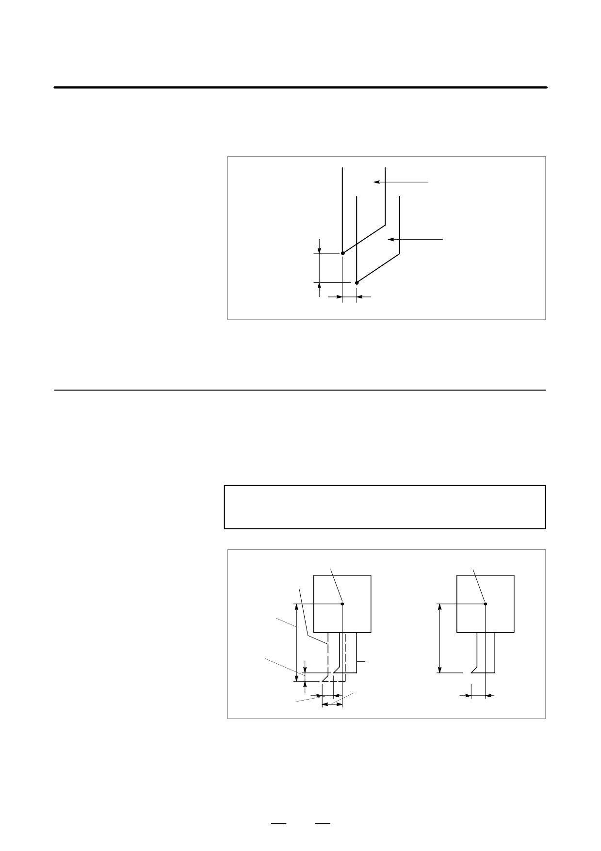
Tool offset is used to compensate for the difference when the tool actually
14.1
used differs from the imagined tool used in programming (usually,
TOOL OFFSET
standard tool).
Standard tool
Actual tool
Offset amount
on X axis
Offset amount
on Z axis
Fig. 14.1 Tool offset
In this unit, there is no G code to specify tool offset.
The tool offset is specified by T code.
14.1.1
Tool geometry offset and tool wear offset are possible to divide the tool
offset to the tool geometry offset for compensating the tool shape or tool
Tool Geometry Offset
mounting position and the tool wear offset for compensating the tool nose
and Tool Wear Offset
wear.
Total value of tool geometry offset value and tool wear offset value is set
as the tool wear offset value without option.
NOTE
Tool geometry offset and tool wear offset are optioned.
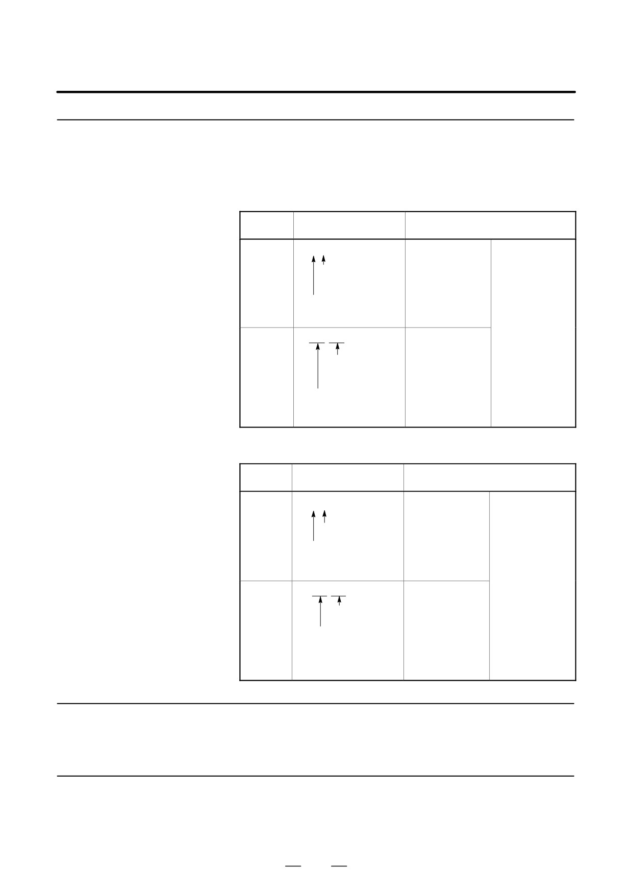
Point on the program
Point on the program
Imaginary tool
X axis
geometry
Offset
offset
amount
value
on X axis
X axis
wear
Actual
offset
tool
value
Z axis
Z axis
wear
geometry
Offset
offset
offset
amount
value
value
on Z axis
Fig. 14.1.1 (a) Difference the
Fig. 14.1.1 (b) Not difference the
tool geometry offset from tool
tool geometry offset from tool
wear offset
wear offset
220
B-63524EN/01
PROGRAMMING
14. COMPENSATION FUNCTION
14.1.2
There are two methods for specifying a T code as shown in Table 14.1.2
(a) and Table 14.1.2 (b).
T Code for Tool Offset
Format
D Lower digit of T code
Table 14.1.2 (a)
specifies geometry and
Kind of
Parameter setting for specifying of
wear offset number
Meaning of T code
T code
offset No.
2-digit
T f f
When LD1, bit 0 of
When LGN, bit 1
command
parameter
of parameter
Tool wear and tool
No.5002, is set to
No.5002, is set to
geometry offset
1, a tool wear off-
0, the tool geome-
number
set number is spe-
try offset number
Tool selection
cified with the last
and tool wear off-
digit of a T code.
set number speci-
fied for a certain
4-digit
T ff ff
When LD1, bit 0 of
tool are the same.
command
parameter
Tool wear and tool
No.5002, is set to
geometry offset
0, a tool wear off-
number
set number is spe-
Tool selection
cified with the last
two digits of a T
code.
D Lower digit of T code
Table 14.1.2 (b)
specifies wear offset
Kind of
Parameter setting for specifying of
number and higher digit
Meaning of T code
T code
offset No.
number specifies tool
selection number and
2-digit
When LD1, bit 0 of
When LGN, bit 1
T f f
command
parameter
of parameter
geometry offset number
No.5002, is set to
No.5002, is set to
Tool wear offset
1, a tool wear off-
1, the tool geome-
number
Tool selection and tool
set number is spe-
try offset number
geometry offset num-
cified with the last
and tool wear off-
ber
digit of a T code.
set number speci-
fied for a certain
4-digit
T ff ff
When LD1, bit 0 of
tool are the same.
command
parameter
Tool wear offset
No.5002, is set to
number
0, a tool wear off-
Tool selection and
set number is spe-
tool geometry offset
cified with the last
number
two digits of a T
code.
14.1.3
Tool selection is made by specifying the T code corresponding to the tool
number. Refer to the machine tool builder’s manual for the relationship
Tool Selection
between the tool selection number and the tool.
14.1.4
Tool offset number has two meanings.
It is specifies the offset distance corresponding to the number that is
Offset Number
selected to begin the offset function. A tool offset number of 0 or 00
indicates that the offset amount is 0 and the offset is cancelled.
221
14. COMPENSATION FUNCTION
PROGRAMMING
B-63524EN/01
14.1.5
There are two types of offset. One is tool wear offset and the other is tool
geometry offset.
Offset
Explanations
D Tool wear offset
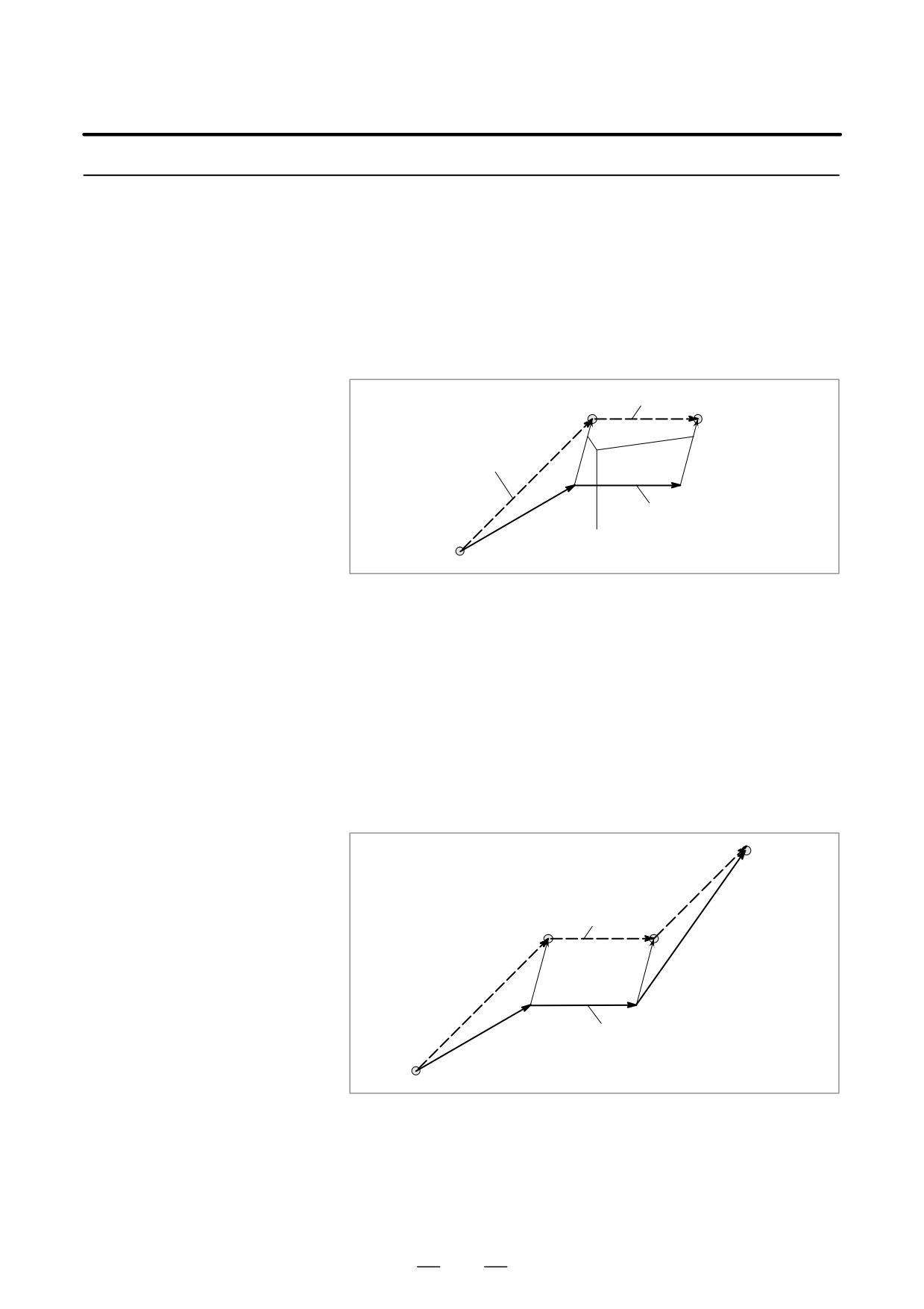
The tool path is offset by the X, Y, and Z wear offset values for the
programmed path. The offset distance corresponding to the number
specified by the T code is added to or subtracted from the and position of
each programmed block.
Tool path after offset
This block contains the offset
command with T code
Programmed path
Compensation by offset X, Z (offset vector)
Fig. 14.1.5 (a) Movement of offset (1)
D Offset vector
In Fig. 14.1.5 (a), the vector with offset X, Y, and Z is called the offset
vector. Compensation is the same as the offset vector.
D Offset cancel
Offset is cancelled when T code offset number 0 or 00 is selected. At the
end of the cancelled block, the offset vector becomes 0.
N1 X50.0 Z100.0 T0202 ; Creates the offset vector corresponding
to offset number 02
N2 X200.0 ;
N3 X100.0 Z250.0 T0200 ; Specifying offset number 00 deletes the
offset vector.
Tool path after offset
N2
Programmed path
N1
Fig. 14.1.5 (b) Movement of offset (2)
When the power is first turned on , and the reset key on the MDI units is
pushed or the reset signal is input to the CNC from the machine tool, the
offset is cancelled.
Parameter LVK (No. 5003#6) can be set so that offset will not be cancelled
by pressing the reset key or by reset input.
222
B-63524EN/01
PROGRAMMING
14. COMPENSATION FUNCTION
D Only T code
When only a T code is specified in a block, the tool is moved by the wear
offset value without a move command. The movement is performed at
rapid traverse rate in the G00 mode . It is performed at feedrate in other
modes.
When a T code with offset number 0 or 00is specified by itself, movement
is performed to cancel the offset.
WARNING
When G50 X_Z_T_ ; is specified
Tool is not moved.
The coordinate system in which the coordinate value of the
tool position is (X,Z) is set. The tool position is obtained by
subtracting the wear offset value corresponding to the offset
number specified in the T code.
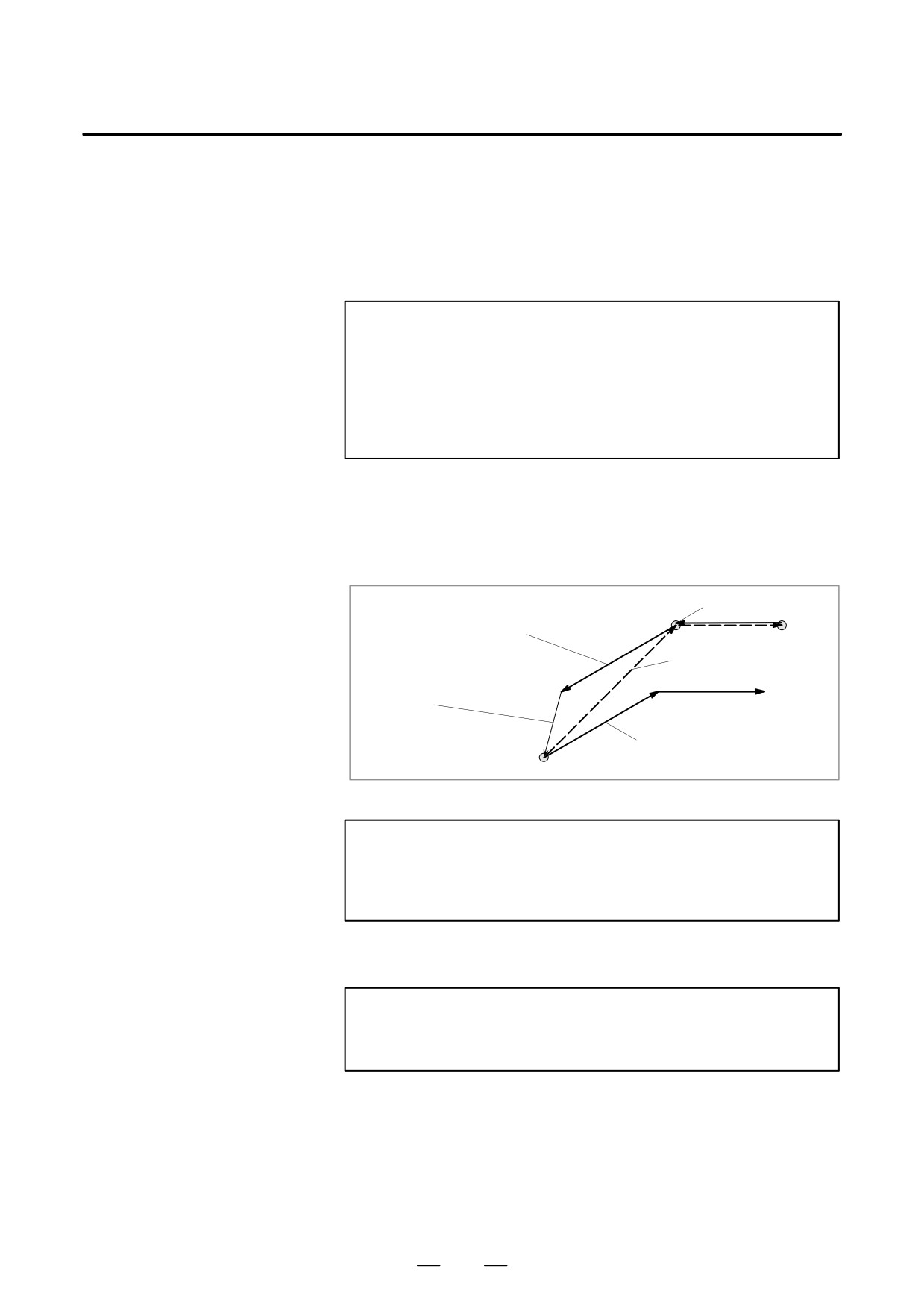
With the tool geometry offset, the work coordinate system is shifted by
D Tool geometry offset
the X, Y, and Z geometry offset amounts. Namely, the offset amount
corresponding to the number designated with the code is added to or
subtracted from the current position.
Absolute command
Programmed path after work
coordinate system shift
Tool path after offset
Offset amount by tool
geometry offset in X, Z
axis (offset vector
Programmed path before
work coordinate system shift
Fig. 14.1.5 (c) Movement of tool geometry offset
NOTE
As well as wear offset, the tool can be compensated by
parameter setting LGT(No.5002#4) to add or subtract the
programmed end point of each block.
D Offset cancel
Specifying offset number 0, 00, or 0000 cancels offset.
NOTE
When LGC, bit 5 of parameter No.5002, is set to 0,
specifying offset number 0 or 00 does not cancel offset.
223
14. COMPENSATION FUNCTION
PROGRAMMING
B-63524EN/01
Examples
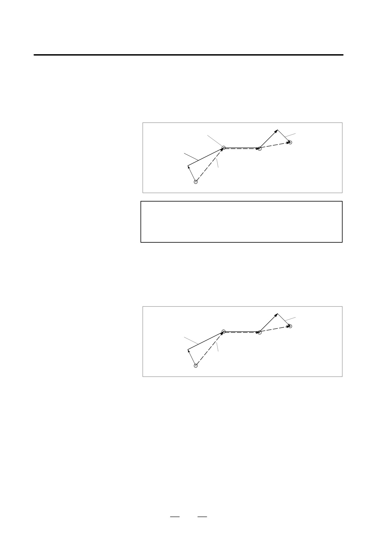
1. When a tool geometry offset number and tool wear offset number are
specified with the last two digits of a T code
(when LGN, bit 1 of parameter No. 5002, is set 0),
N1 X50.0 Z100.0 T0202 ; Specifies offset number 02
N2 Z200.0 ;
N3 X100.0 Z250.0 T0200 ; Cancels offset
Absolute command
Offset cancel
Programmed
N3
path after work
N2
coordinate
N1
system shift
Tool path after offset
Offset
NOTE
When LGC, bit 5 of parameter No.5002, is set to 0,
specifying offset number 0 does not cancel tool geometry
offset.
2. Assume that geometry offset is not cancelled with offset No. 0
(Set the parameter (No. 5002#1).)
N1 X50.0 Z100.0 T0202 ; Tool selection number
(specified tool
geometry offset number 02)
N2 Z200.0 ;
N3 X100.0 Z250.0 T0000 ; Cancels offset
Offset cancel
Programmed
N3
path after work
N2
coordinate
N1
system shift
Tool path after offset
Offset
224
B-63524EN/01
PROGRAMMING
14. COMPENSATION FUNCTION
14.1.6
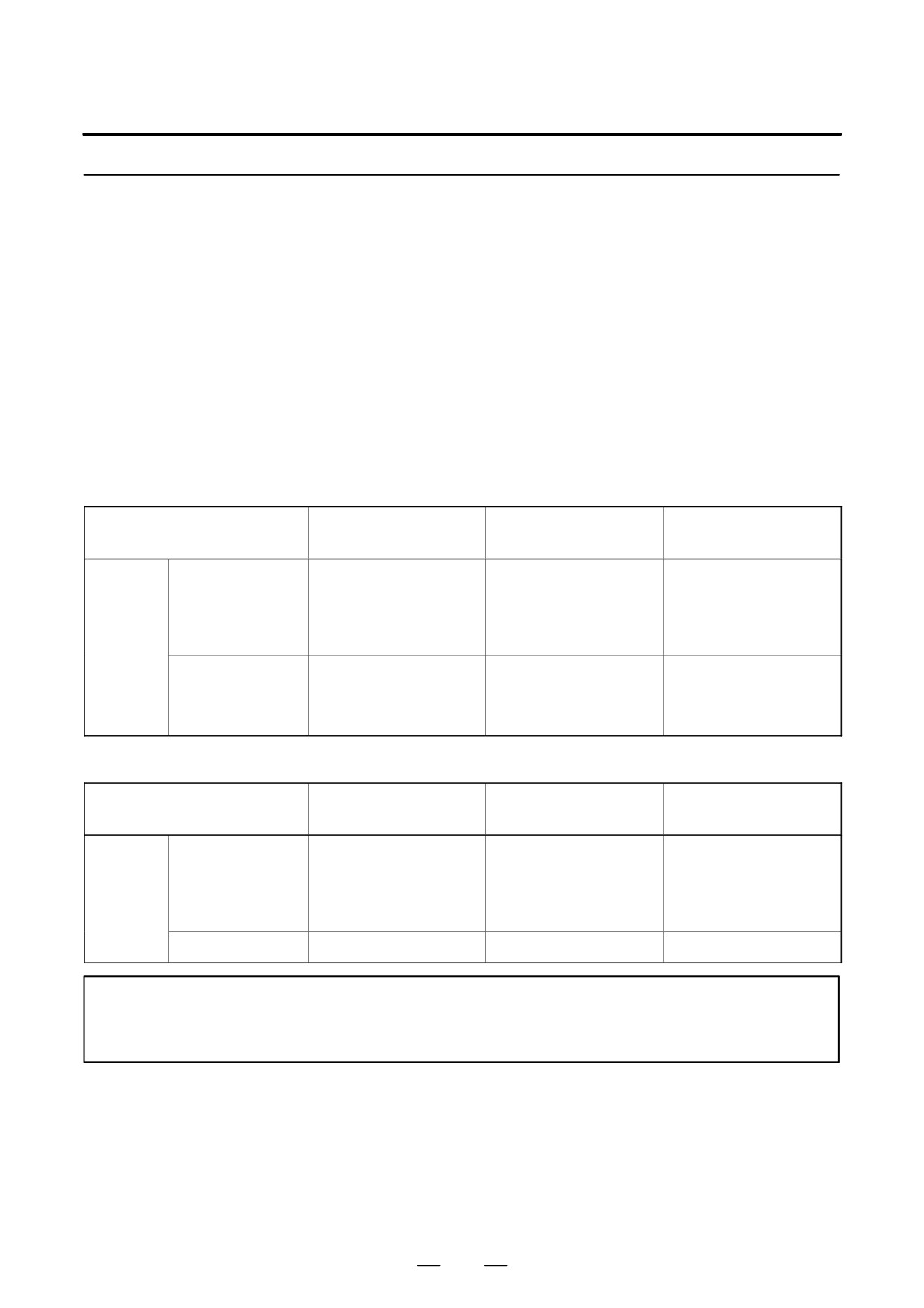
This section describes the following operations when tool position offset
is applied: G53, G28, G30, and G30.1 commands, manual reference
G53, G28, G30, and
position return, and the canceling of tool position offset with a T00
G30.1 Commands
command.
When Tool Position
Offset is Applied
Explanations
D Reference position
Executing reference position return (G28) or a G53 command when tool
return (G28) and G53
position offset is applied does not cancel the tool position offset vector.
command when tool
The absolute position display is as follows, however, according to the
position offset is applied
setting of bit 4 (LGT) of parameter No. 5002.
LGT = 0 (Tool geometry compensation is based on shift of the coordinate system.)
Tool position offset
Tool geometry
Tool wear
(without option)
compensation
compensation
Absolute
Block for reference
The vector is not reflected.
The shift is reflected.
The vector is not reflected.
position
position return or
The coordinates are dis-
Coordinates shifted ac-
The coordinates are dis-
coordinate
G53 command
played as if the offset had
cording to the tool geome-
played as if the offset had
display
been temporarily can-
try compensation are dis-
been temporarily can-
celed.
played.
celed.
Next block
The vector is reflected.
Coordinates shifted ac-
The vector is reflected.
cording to the tool geome-
try compensation are dis-
played.
LGT = 1 (Tool geometry compensation is based on tool movement.)
Tool position offset
Tool geometry
Tool wear
(without option)
compensation
compensation
Absolute
Block for reference
The vector is not reflected.
The vector is not reflected.
The vector is not reflected.
position
position return or
The coordinates are dis-
The coordinates are dis-
The coordinates are dis-
coordinate
G53 command
played as if the offset had
played as if the offset had
played as if the offset had
display
been temporarily can-
been temporarily can-
been temporarily can-
celed.
celed.
celed.
Next block
The vector is reflected.
The vector is reflected.
The vector is reflected.
NOTE
Bit 6 (DAL) of parameter No. 3104 is set to 0 (the actual positions to which the tool position offset
is applied are displayed in the absolute position display).
225
14. COMPENSATION FUNCTION
PROGRAMMING
B-63524EN/01
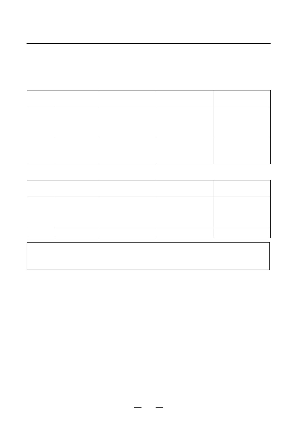
D Manual reference
Executing manual reference position return when tool position offset is
position return when tool
applied does not cancel the tool position offset vector. The absolute
position offset is applied
position display is as follows, however, according to the setting of bit 4
(LGT) of parameter No. 5002.
LGT = 0 (Tool geometry compensation is based on shift of the coordinate system.)
Tool position offset
Tool geometry
Tool wear
(without option)
compensation
compensation
Absolute
Upon manual refer-
The vector is not reflected.
The shift is reflected.
The vector is not reflected.
position
ence position return
The coordinates are dis-
Coordinates shifted ac-
The coordinates are dis-
coordinate
played as if the offset had
cording to tool geometry
played as if the offset had
display
been temporarily can-
compensation are dis-
been temporarily can-
celed.
played.
celed.
Next block
The vector is reflected.
Coordinates shifted ac-
The vector is reflected.
cording to tool geometry
compensation are dis-
played.
LGT = 1 (Tool geometry compensation is based on tool movement.)
Tool position offset
Tool geometry
Tool wear
(without option)
compensation
compensation
Absolute
Upon manual refer-
The vector is not reflected.
The vector is not reflected.
The vector is not reflected.
position
ence position return
The coordinates are dis-
The coordinates are dis-
The coordinates are dis-
coordinate
played as if the offset had
played as if the offset had
played as if the offset had
display
been temporarily can-
been temporarily can-
been temporarily can-
celed.
celed.
celed.
Next block
The vector is reflected.
The vector is reflected.
The vector is reflected.
NOTE
Bit 6 (DAL) of parameter No. 3104 is set to 0 (the actual positions to which the tool position offset
is applied are displayed in the absolute position display).
226
B-63524EN/01
PROGRAMMING
14. COMPENSATION FUNCTION
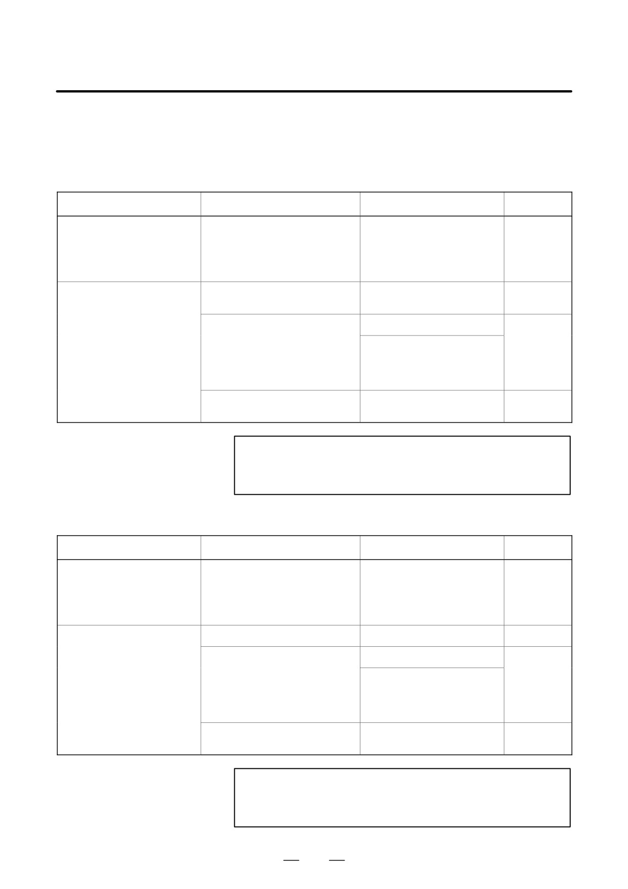
D Canceling tool position
Whether specifying T00 alone, while tool position offset is applied,
offset with T00
cancels the offset depends on the settings of the following parameters:
When the tool geometry/wear compensation option is selected
LGN = 0
LGN (No.5002#1)
LGT (No.5002#4)
LGC (No.5002#5)
The geometry offset number is:
Geometry compensation is applied:
The geometry offset is:
Result
0: Same as the wear offset
0: Based on shift of the
0: Not canceled with T00
number
coordinate system
1: Canceled with T00
1: Same as the tool selection
1: Based on movement of the tool
number
LGT=0
LGT=0
LGC=0
Not canceled
LGC=1
Canceled
LWM (No.5002#6)
Tool position offset is applied:
0: By means of T code
1: By means of movement
along axis
LGT=1
LWM=0
Canceled
LWM=1
Not canceled
NOTE
1
When LGT=0, LWM is unrelated.
2
When LGT=1, LGC is unrelated, even when LGN = 0.
LGN = 1
LGN (No.5002#1)
LGT (No.5002#4)
LGC (No.5002#5)
The geometry offset number is:
Geometry compensation is applied:
The geometry offset is:
Result
0: Same as the wear offset
0: Based on shift of the
0: Not canceled with T00
number
coordinate system
1: Canceled with T00
1: Same as the tool selection
1: Based on movement of the tool
number
LGT=0
LGT=0
LGC is unrelated.
Canceled
LWM (No.5002#6)
Tool position offset is applied:
0: By means of T code
1: By means of movement
along axis
LGT=1
LWM=0
Canceled
LWM=1
Not canceled
NOTE
1
When LGT = 0, LWM is unrelated.
2
When LGT = 1, LGC is unrelated.
227
14. COMPENSATION FUNCTION
PROGRAMMING
B-63524EN/01
When the tool geometry/wear compensation option is not selected
LGN (No.5002#1)
LGT (No.5002#4)
LGC (No.5002#5)
The geometry offset number is:
Geometry compensation is
The geometry offset is:
Result
0: Same as the wear offset
applied:
0: Not canceled with T00
number
0: Based on shift of the
1: Canceled with T00
1: Same as the tool selection
coordinate system
number
1: Based on movement of the
tool
LGN is unrelated.
LGT is unrelated.
LGC is unrelated.
The tool position offset number
Tool position offset is always
LWM (No.5002#6)
always uses the low-order digits.
applied based on the movement
of the tool.
Tool position offset is applied:
0: By means of T code
1: By means of movement
along axis
LWM=0
Canceled
LWM=1
Not canceled
228
B-63524EN/01
PROGRAMMING
14. COMPENSATION FUNCTION
It is difficult to produce the compensation necessary to form accurate parts
14.2
when using only the tool offset function due to tool nose roundness in
OVERVIEW OF TOOL
taper cutting or circular cutting. The tool nose radius compensation
NOSE RADIUS
function compensates automatically for the above errors.
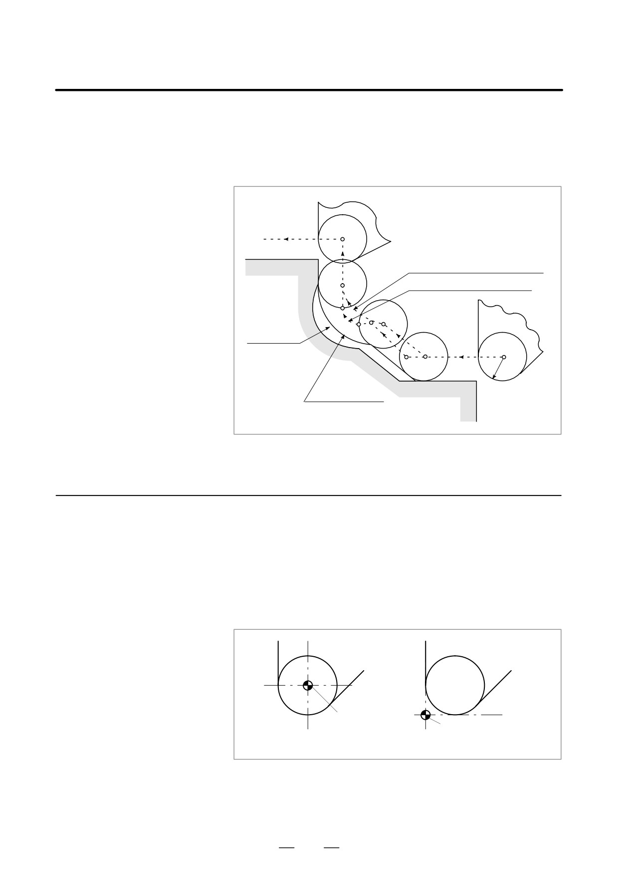
COMPENSATION
Workpiece
Tool path without compensation
Ç
Tool path with compensation
ÇÇ
Insufficient
ÇÇ
Tool nose
depth of
ÇÇÇ
cutting
ÇÇÇÇ
ÇÇÇÇ
R
ÇÇÇÇ
Shape processed without tool
nose radius compensation
Fig 14.2 Tool path of tool nose radius compensation
14.2.1
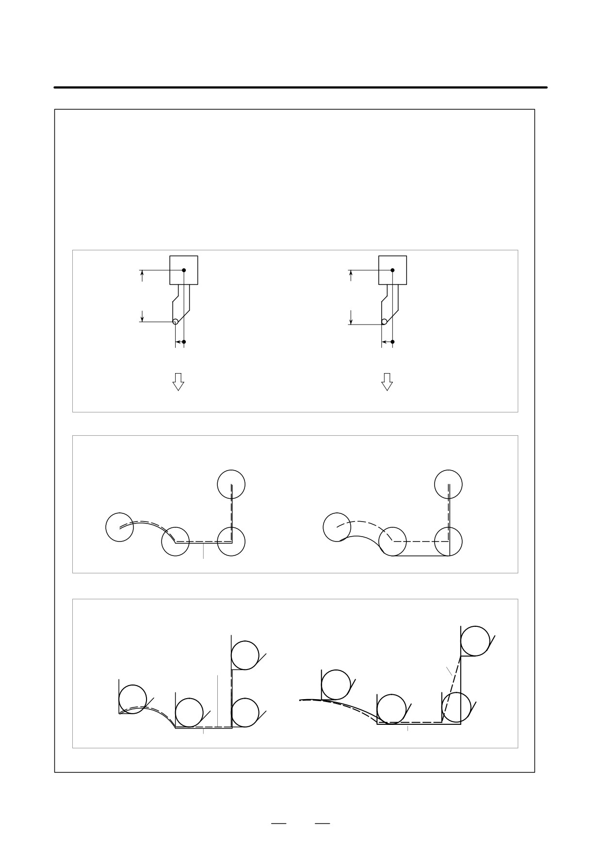
The tool nose at position A in following figure does not actually exist.
The imaginary tool nose is required because it is usually more difficult to
Imaginary Tool Nose
set the actual tool nose radius center to the start position than the
imaginary tool nose (Note).
Also when imaginary tool nose is used, the tool nose radius need not be
considered in programming.
The position relationship when the tool is set to the start position is shown
in the following figure.
A
Start position
Start position
When programmed using the
When programmed using the
tool nose center
imaginary tool nose
Fig. 14.2.1 (a) Tool nose radius center and imaginary tool nose
229
14. COMPENSATION FUNCTION
PROGRAMMING
B-63524EN/01
CAUTION
In a machine with reference positions, a standard position like the turret center can be placed
over the start position. The distance from this standard position to the nose radius center or
the imaginary tool nose is set as the tool offset value.
Setting the distance from the standard position to the tool nose radius center as the offset
value is the same as placing the tool nose radius center over the start position, while setting
the distance from the standard position to the imaginary tool nose is the same as placing the
imaginary tool nose over the standard position. To set the offset value, it is usually easier to
measure the distance from the standard position to the imaginary tool nose than from the
standard position to the tool nose radius center.
OFX
OFX
(Tool offset
(Tool offset
in X axis)
in X axis)
OFZ
OFZ
(Tool offset
(Tool offset
in Z axis)
in Z axis)
Setting the distance from the standard position
Setting the distance from the standard position to
to the tool nose center as the tool offset value
the imaginary tool nose center as the tool offset
value
The start position is placed over the tool nose center The start position is placed over the imaginary tool
nose
Fig. 14.2.1 (b) Tool offset value when the turret center is placed over the start position
Unless tool nose radius compensation is
If tool nose radius compensation is used, accu-
performed, the tool nose center path is the
rate cutting will be performed.
same as the programmed path.
Start-
Start-
Tool nose center path
Tool nose center path
up
up
Programmed path
Programmed path
Fig. 14.2.1 (c) Tool path when programming using the tool nose center
Without tool nose radius compensation, the
With tool nose radius compensation, accurate
imaginary tool nose path is the same as the
cutting will be performed.
programmed path.
Imaginary tool
Imaginary tool
nose path
nose path
Start-
Start-
up
up
Programmed path
Programmed path
Fig. 14.2.1 (d) Tool path when programming using the imaginary tool nose
230
B-63524EN/01
PROGRAMMING
14. COMPENSATION FUNCTION
14.2.2
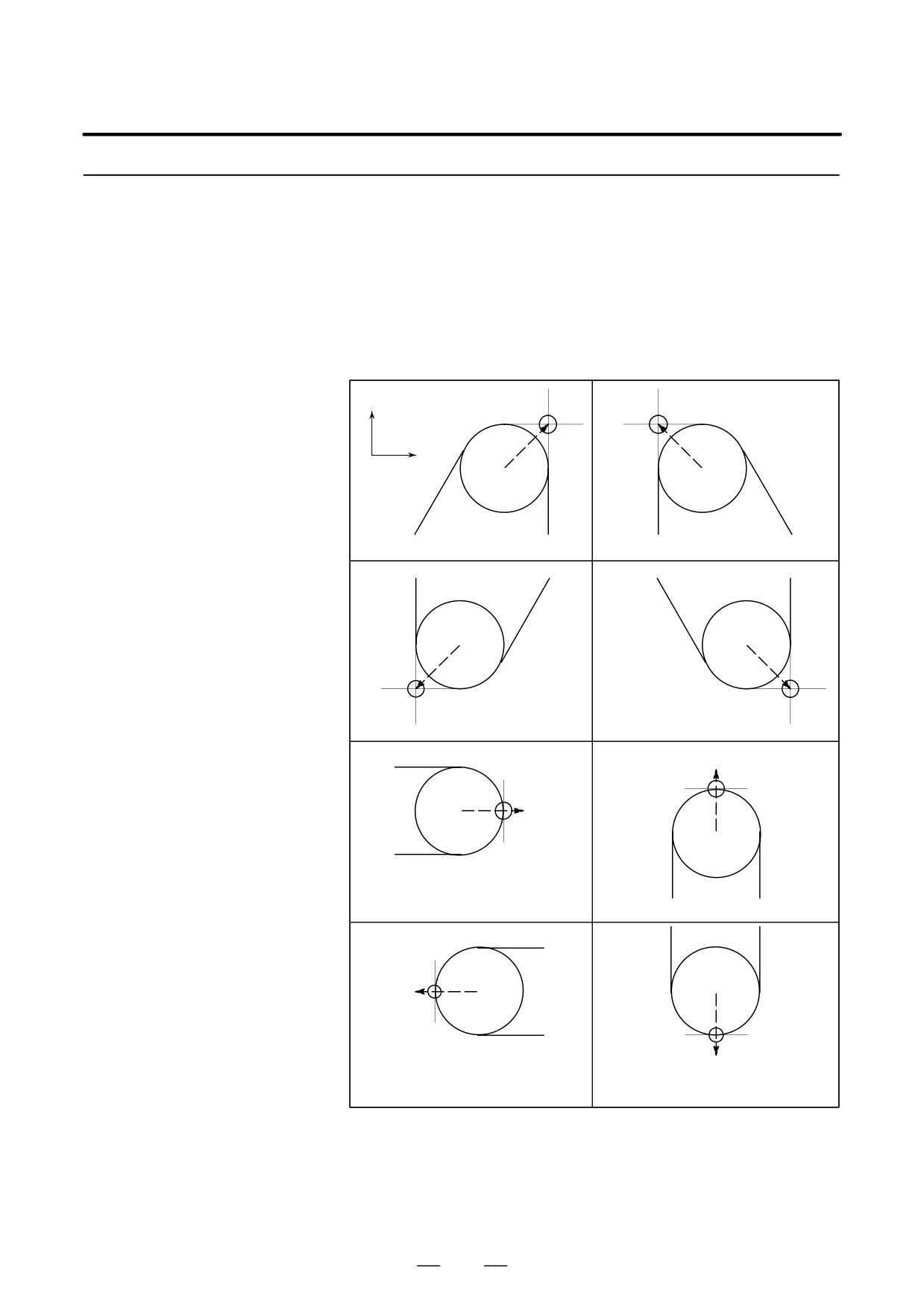
The direction of the imaginary tool nose viewed from the tool nose center
is determined by the direction of the tool during cutting, so it must be set
Direction of Imaginary
in advance as well as offset values.
Tool Nose
The direction of the imaginary tool nose can be selected from the eight
specifications shown in the Fig.
14.2.2 below together with their
corresponding codes.
This Fig 14.2.2 illustrates the relation between the tool and the start
position. The following apply when the tool geometry offset and tool
wear offset option are selected.
X
Z
Imaginary tool nose number 1
Imaginary tool nose number 2
Imaginary tool nose number 3
Imaginary tool nose number 4
Imaginary tool nose number 5
Imaginary tool nose number 6
Imaginary tool nose number 7
Imaginary tool nose number 8
Fig. 14.2.2 Direction of imaginary tool nose
231
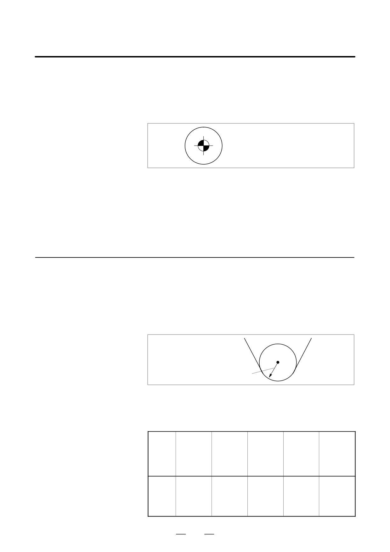
14. COMPENSATION FUNCTION
PROGRAMMING
B-63524EN/01
Imaginary tool nose numbers 0 and 9 are used when the tool nose center
coincides with the start position. Set imaginary tool nose number to
address OFT for each offset number.
Bit 7 (WNP) of parameter No. 5002 is used to determine whether the tool
geometry offset number or the tool wear offset number specifies the
direction of the virtual tool nose for tool nose radius compensation.
Imaginary tool nose number 0 to 9
Limitations
D Plane selection
Virtual tool nose directions 1 to 8 can be used only in the G18 (Z-X) plane.
For virtual tool nose 0 or 9, compensation is applied in both the G17 and
G19 planes.
14.2.3
Offset Number and
Offset Value
Explanations
D Offset number and offset
value
Tool nose radius compensation value
(Tool nose radius value)
This value is set from the MDI according to the offset number.
When the options of tool geometry compensation and tool wear
compensation are selected, offset values become as follows :
Table 14.2.3 (a) Offset number and offset value
OFR
OFT
OFX
OFZ
(Tool nose
OFY
(Direction
Offset
(Offset
(Offset
radius
(Offset
of imagi-
number
value on X
value on Z
com-
value on Y
nary tool
axis)
axis)
pensation
axis)
nose)
value)
01
0.040
0.020
0.20
1
0.030
02
0.060
0.030
0.25
2
0.040
:
:
:
:
:
:
98
0.050
0.015
0.12
6
0.025
99
0.030
0.025
0.24
3
0.035
232
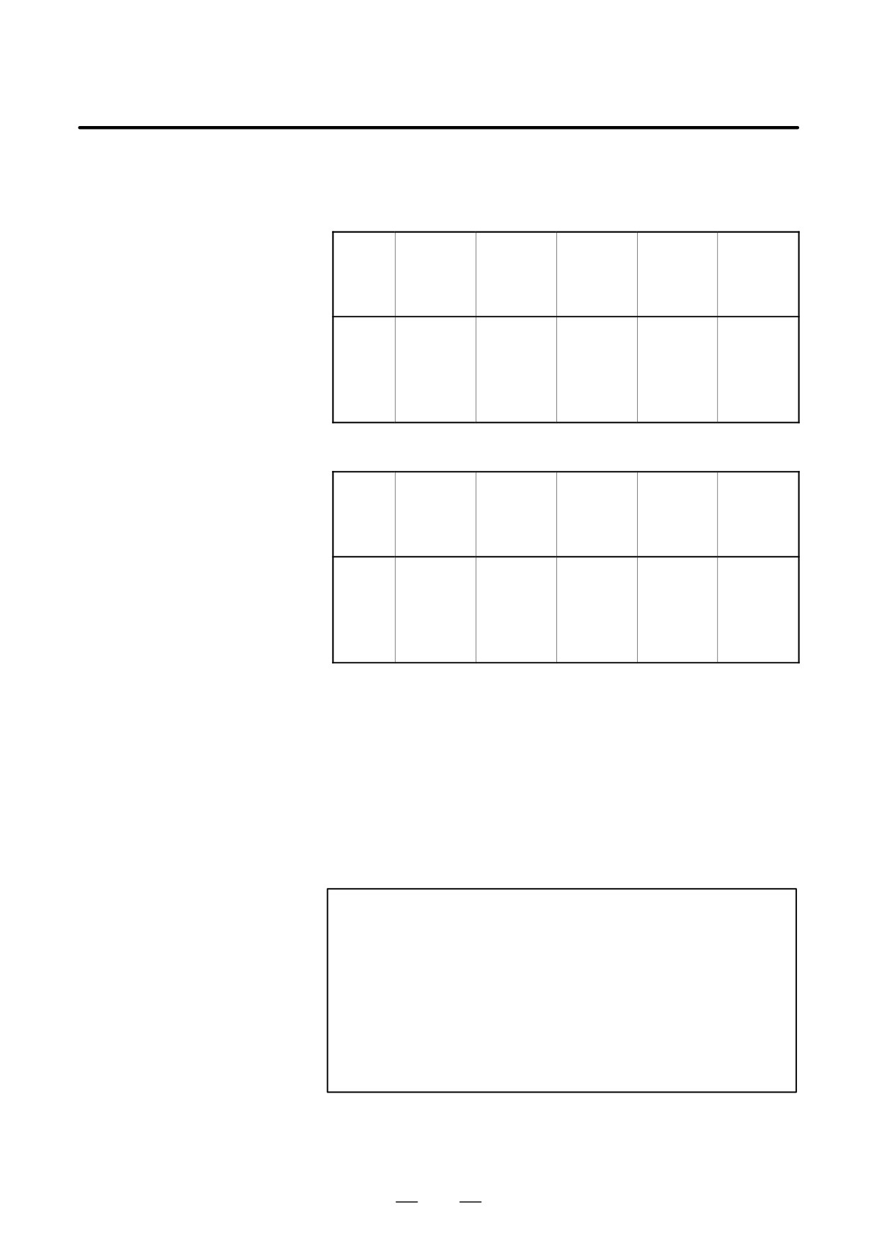
B-63524EN/01
PROGRAMMING
14. COMPENSATION FUNCTION
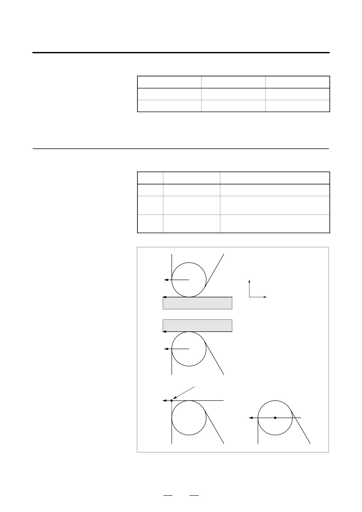
When the options of tool geometry compensation and tool wear
compensation are selected, the offset values become as follows :
Table 14.2.3 (b) Tool geometry offset
OFGX
OFGZ
OFGR
OFGY
Geome-
OFT
(X-axis
(Z-axis
(Tool nose
(Y-axis
try
(Imaginary
geometry
geometry
radius ge-
geometry
offset
tool nose
offset
offset
ometry off-
offset
number
direction)
amount)
amount)
set value)
amount)
G01
10.040
50.020
0
1
70.020
G02
20.060
30.030
0
2
90.030
G03
0
0
0.20
6
0
G04
:
:
:
:
:
G05
:
:
:
:
:
:
:
:
:
:
:
Table 14.2.3 (c) Tool wear offset
OFGR
OFGX
OFGZ
OFT
OFGY
Wear
(Tool nose
(X-axis
(Z-axis
(Imaginary
(Y-axis
offset
radius
wear offset
wear offset
tool nose
wear offset
number
wear offset
amount)
amount)
direction)
amount)
value)
W01
0.040
0.020
0
1
0.010
W02
0.060
0.030
0
2
0.020
W03
0
0
0.20
6
0
W04
:
:
:
:
:
W05
:
:
:
:
:
:
:
:
:
:
:
D Tool nose radius
In this case, the tool nose radius compensation value is the sum of the
compensation
geometry or the wear offset value.
OFR=OFGR+OFWR
D Imaginary tool nose
The imaginary tool nose direction may be set for either the geometry
direction
offset or the wear offset.
However, the last designated direction later is effective.
D Command of offset value
A offset number is specified with the same T code as that used for tool
offset. For details, see Subsec. II-14.1.2.
NOTE
When the geometry offset number is made common to the
tool selection by the parameter LGT(No.5002#1)setting
and a T code for which the geometry offset and wear offset
number differ from each other is designated, the imaginary
tool nose direction specified by the geometry offset number
is valid.
Example)
T0102
OFR=RFGR01+OFWR02
OFT=OFT01
233
14. COMPENSATION FUNCTION
PROGRAMMING
B-63524EN/01
D Setting range of offset
The range of the offset value is an follows :
value
Increment system
metric system
Inch system
IS-B
0 to "999.999 mm
0 to "99.9999 inch
IS-C
0 to "999.9999 mm
0 to "99.99999 inch
The offset value corresponding to the offset number 0 is always 0.
No offset value can be set to offset number 0.
14.2.4
In tool nose radius compensation, the position of the workpiece with
respect to the tool must be specified.
Work Position and
Move Command
G code
Workpiece position
Tool path
G40
(Cancel)
Moving along the programmed path
G41
Right side
Moving on the left side the programmed
path
G42
Left side
Moving on the right side the programmed
path
The tool is offset to the opposite side of the workpiece.
X axis
G42
Z axis
Workpiece
G41
The imaginary tool nose is
on the programmed path.
G40
G40
Imaginary tool nose
Imaginary tool
number 1 to 8
nose number 0
234
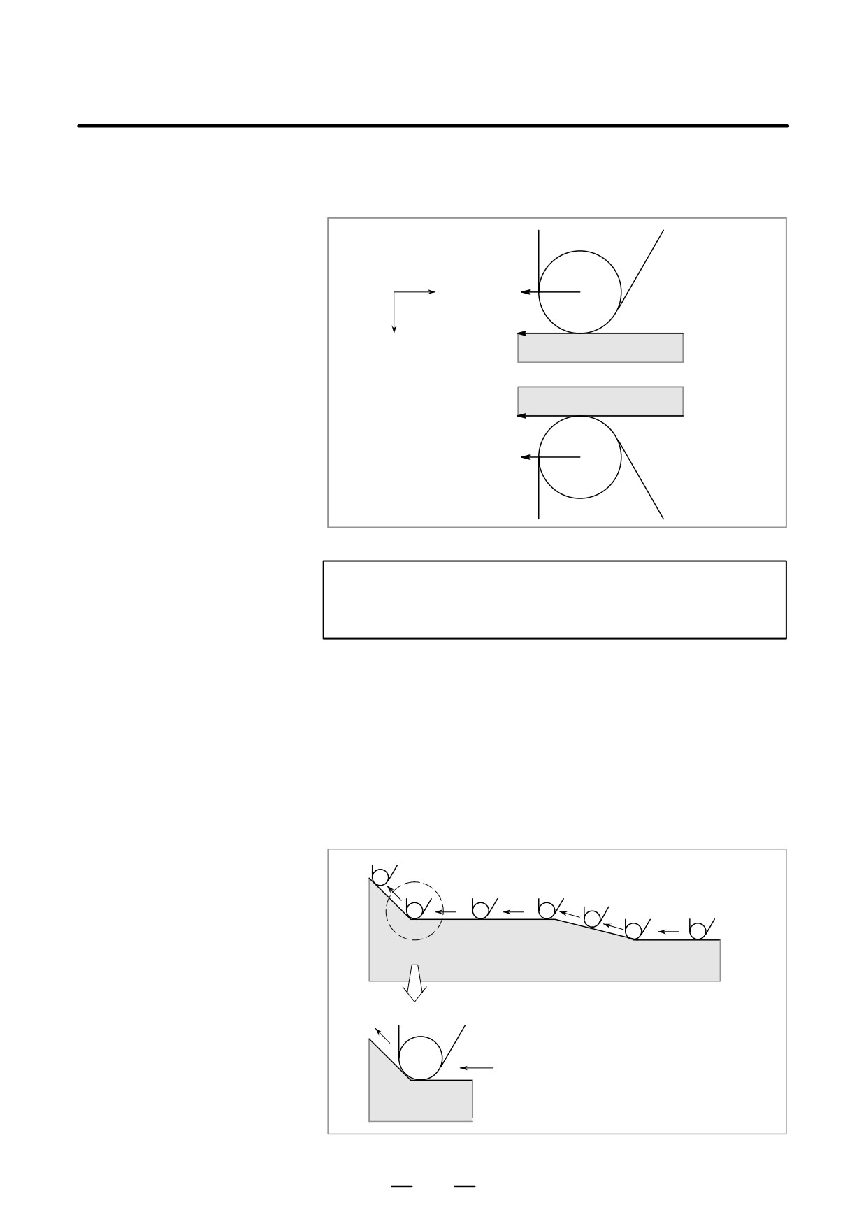
B-63524EN/01
PROGRAMMING
14. COMPENSATION FUNCTION
The workpiece position can be changed by setting the coordinate system
as shown below.
Z axis
G41 (the workpiece is
on the left side)
X axis
Workpiece
G42 (the workpiece is
Note
on the right side)
NOTE
If the tool nose radius compensation value is negative, the
workpiece position is changed.
G40, G41, and, G42 are modal.
Don’t specify G41 while in the G41 mode. If you do, compensation will
not work properly.
Don’t specify G42 while in the G42 mode for the same reason.
G41 or G42 mode blocks in which G41 or G42 are not specified are
expressed by (G41) or (G42) respectively.
D Tool movement when the
When the tool is moving, the tool nose maintains contact with the
workpiece position does
workpiece.
not change
(G42)
(G42)
(G42)
(G42)
(G42)
(G42)
Enlarged
diagram
235
14. COMPENSATION FUNCTION
PROGRAMMING
B-63524EN/01
D Tool movement when the
The workpiece position against the toll changes at the corner of the
workpiece position
programmed path as shown in the following figure.
changes
A
C
Workpiece
G41
position
G42
Workpiece
B
position
B
A
C
G41
G42
Although the workpiece does not exist on the right side of the
programmed path in the above case. the existence of the workpiece is
assumed in the movement from A to B. The workpiece position must not
be changed in the block next to the start-up block. In the above example,
if the block specifying motion from A to B were the start-up block, the
tool path would not be the same as the one shown.
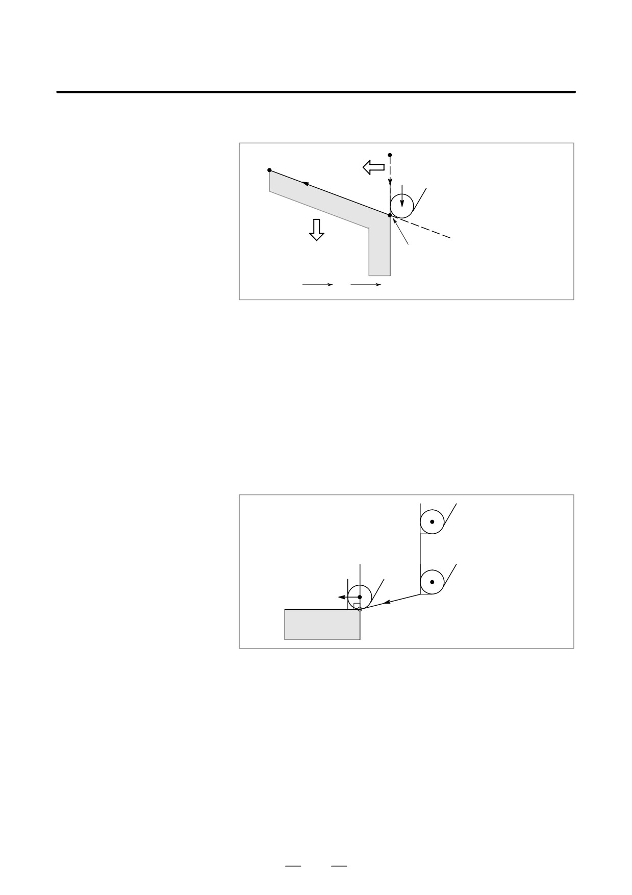
D Start-up
The block in which the mode changes to G41 or G42 from G40 is called
the start-up block.
G40 _ ;
G41 _ ; (Start-up block)
Transient tool movements for offset are performed in the start-up block.
In the block after the start-up block, the tool nose center is positioned
Vertically to the programmed path of that block at the start position.
G40
(G42)
G42 (Start-up)
236
B-63524EN/01
PROGRAMMING
14. COMPENSATION FUNCTION
D Offset cancel
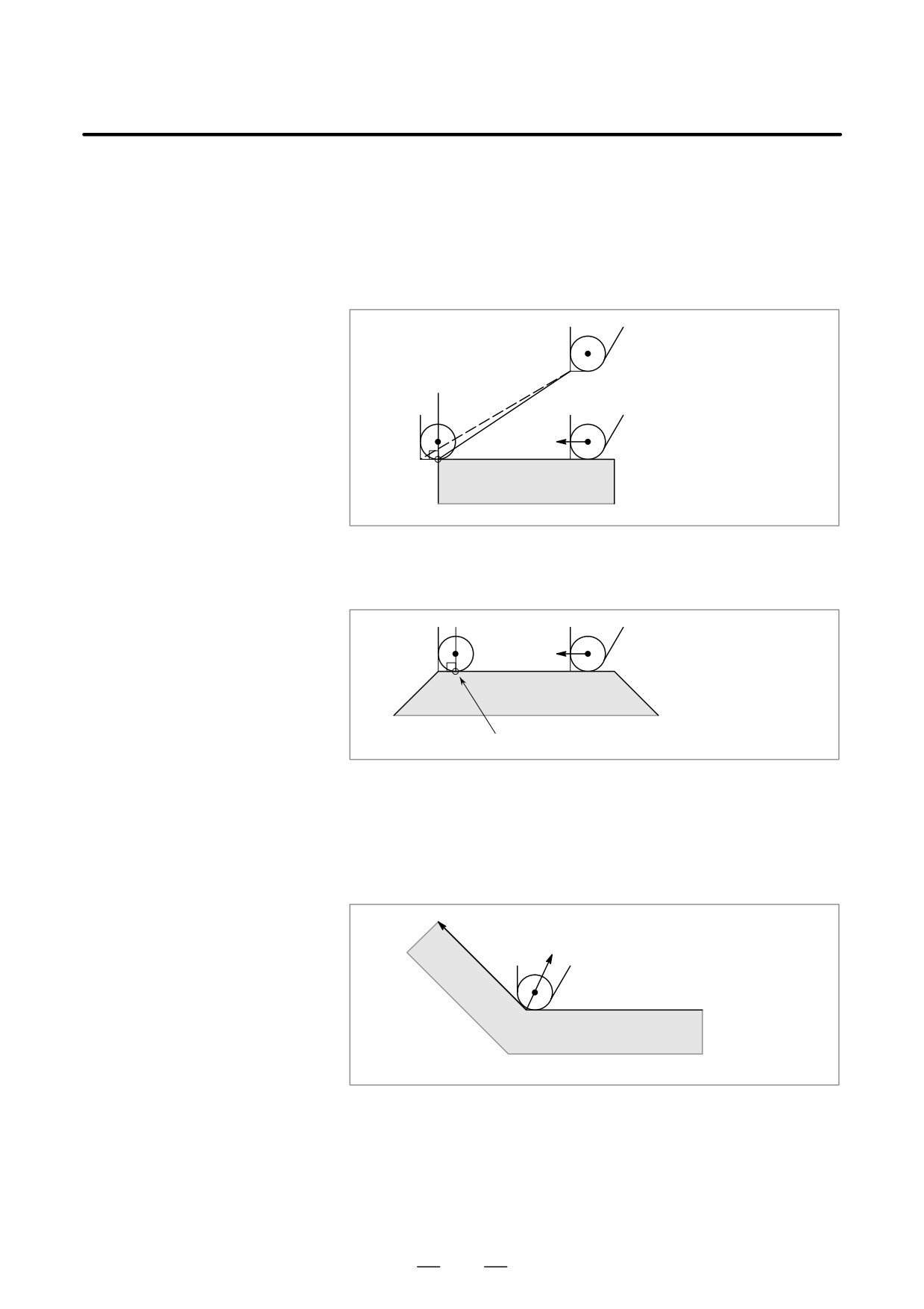
The block in which the mode changes to G40 from G41 or G42 is called
the offset cancel block.
G41 _ ;
G40 _ ; (Offset cancel block)
The tool nose center moves to a position vertical to the programmed path
in the block before the cancel block. The tool is positioned at the end
position in the offset cancel block (G40) as shown below.
End position
G40
(G42)
D Specification of G41/G42
When is specified again in G41/G42 mode , the tool nose center is
in G41/G42 mode
positioned vertical to the programmed path of the preceding block at the
end position of the preceding block.
(G42)
(G42)
(G42)
G42 W-500.0 U-500.0 ;
In the block that first specifies G41/G42, the above positioning of the tool
nose center is not performed.
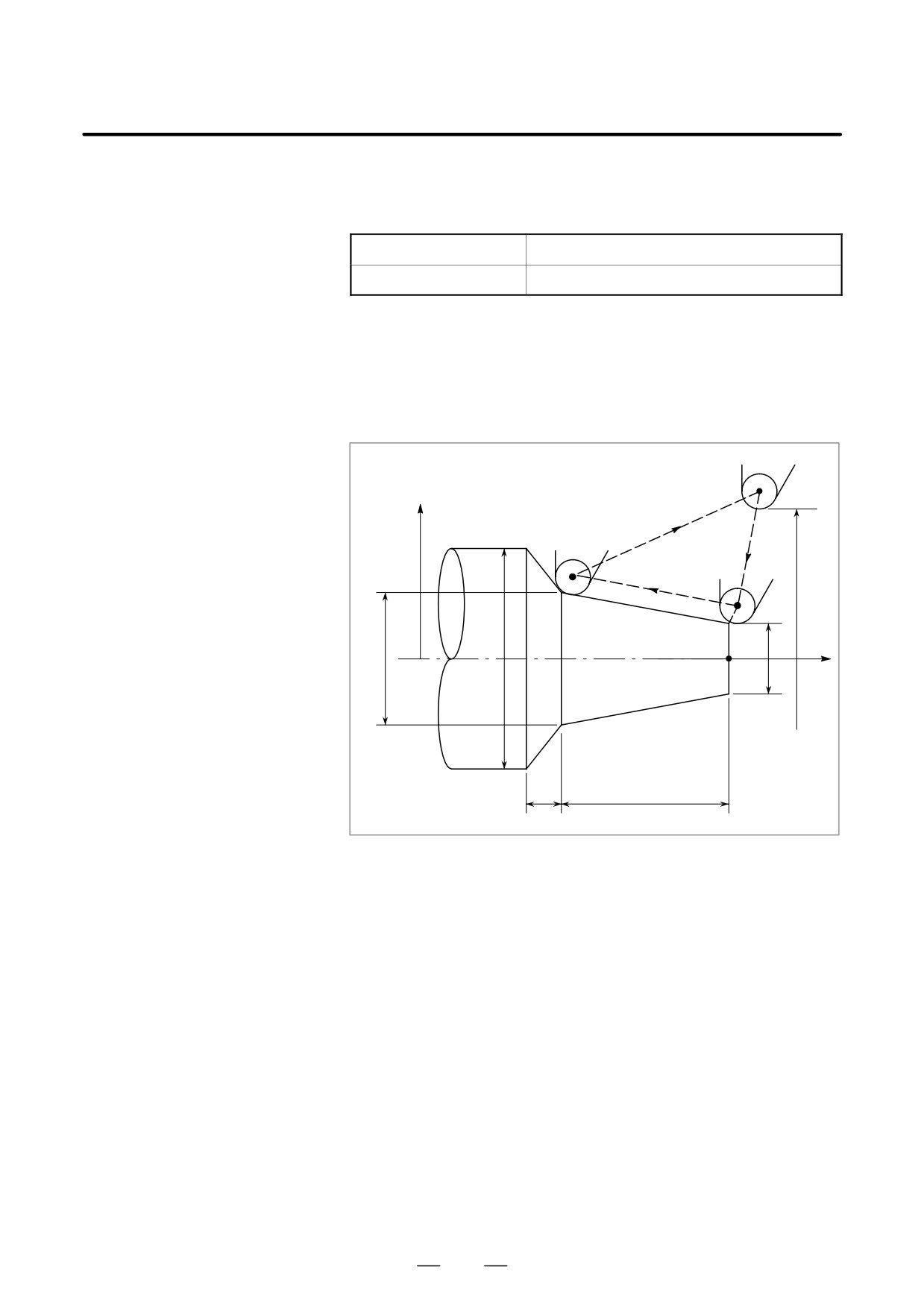
D Tool movement when the
When you wish to retract the tool in the direction specified by X(U) and
moving direction of the
Z(W) cancelling the tool nose radius compensation at the end of
tool in a block which
machining the first block in the figure below, specify the following :
includes a G40
G40 X(U) _ Z(W) _ I _ K _ ;
command is different
from the direction of the
I, K
Moving direction of tool
workpiece
U, W
G40
G42
G40 U_ W_ I_ K_ ;
237
14. COMPENSATION FUNCTION
PROGRAMMING
B-63524EN/01
The workpiece position specified by addresses I and K is the same as that
in the preceding block. If I and/or K is specified with G40 in the cancel
mode, the I and/or K is ignored.
G40 X_ Z_ I_ K_ ;
Tool nose radius compensation
G40 G02 X_ Z_ I_ K_ ;
Circular interpolation
G40 G01 X_ Z_ ;
G40 G01 X_ Z_ I_ K_ ; Offset cancel mode (I and k are ineffective.)
The numeral s followed I and K should always be specified as radius
values.
Examples
X
(3)
f300
(1)
(2)
200
f60
Z
120
0
30
150
(G40 mode)
1.G42 G00 X60.0 ;
2.G01 X120.0 W-150.0 F10 ;
3.G40 G00 X300.0 W150.0 I40.0 K-30.0 ;
238
B-63524EN/01
PROGRAMMING
14. COMPENSATION FUNCTION
14.2.5
Notes on Tool Nose
Radius Compensation
Explanations
D Tool movement when
1.M05 ;
M code output
two or more blocks
2.S210 ;
S code output
without a move
3.G04 X1000 ;
Dwell
command should not be
4.G01 U0 ;
Feed distance of zero
programmed
5.G98 ;
G code only
consecutively
6.G10 P01 X10.0 Z20.0 R0.5 Q2 ; Offset change
If two or more of the above blocks are specified consecutively, the tool
nose center comes to a position vertical to the programmed path of the
preceding block at the end of the preceding block. However, if the no
movement commands is 4 above, the above tool motion is attained only
with one block.
(G42 mode)
Programmed path
N6 W1000.0 ;
N6
N7 S21 ;
N7 N8
N8 M04 ;
U9 U-1000.0 W1000.0 ;
N9
Tool nose center path
D Tool nose radius
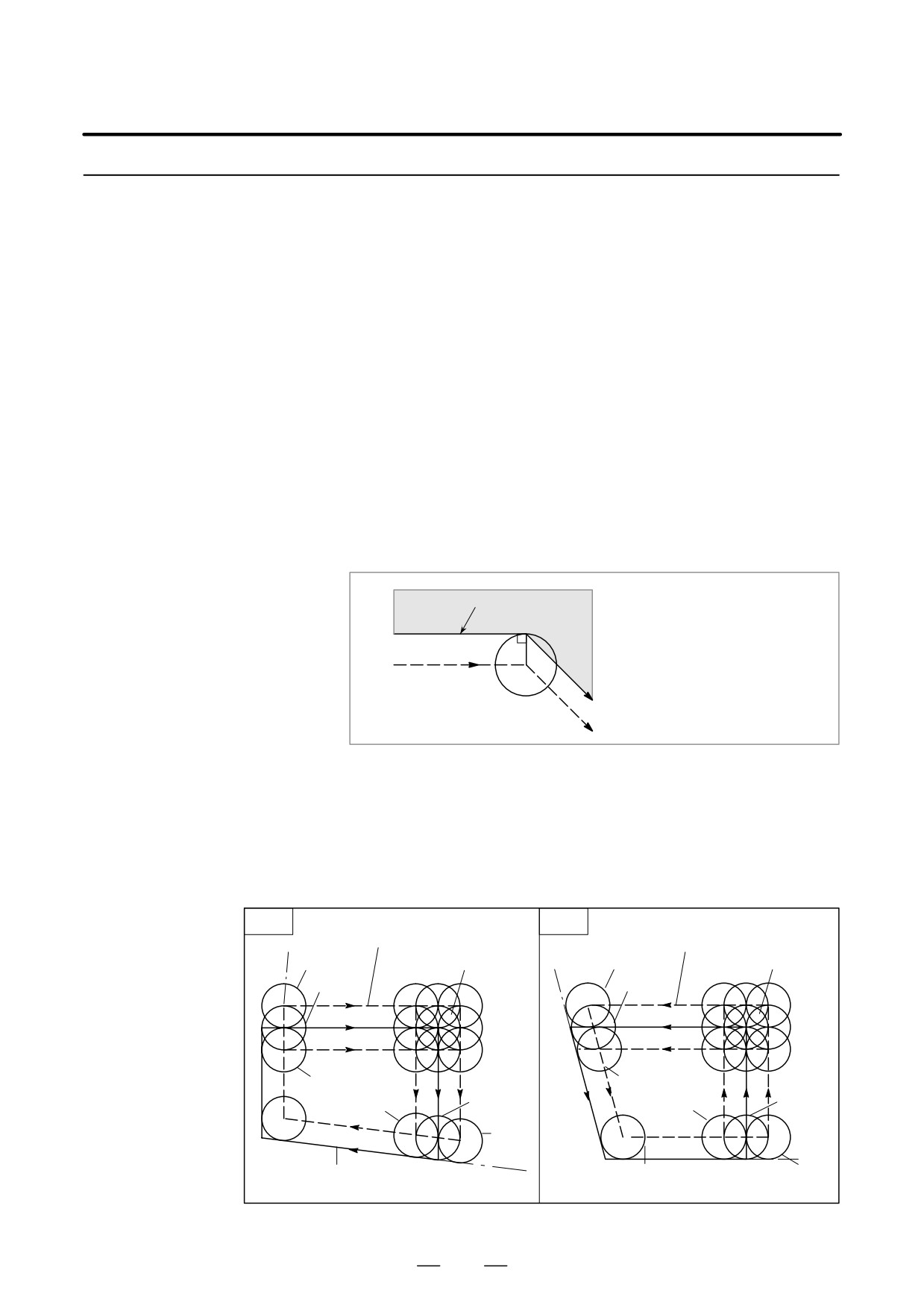
Tool nose radius compensation with G90
(outer diameter/internal
compensation with G90
diameter cutting cycle) or G94 (end face turning cycle) is as follows, :
or G94
1. Motion for imaginary tool nose numbers
For each path in the cycle, the tool nose center path is generally parallel
to the programmed path.
G90
G94
Tool nose center path
Tool nose center path
4, 8, 3
0
4, 8, 3
0
8
8
5, 0, 7
3
5, 0, 7
3
4
4
5
7
5
7
2
2
1, 6, 2
1
1, 6, 2
1
6
6
In all case
1, 4, 5
8, 0, 6
1, 4, 5
8, 0, 6
In all
3, 7, 2
case
Programmed path
Programmed path
3, 7, 2
239
14. COMPENSATION FUNCTION
PROGRAMMING
B-63524EN/01
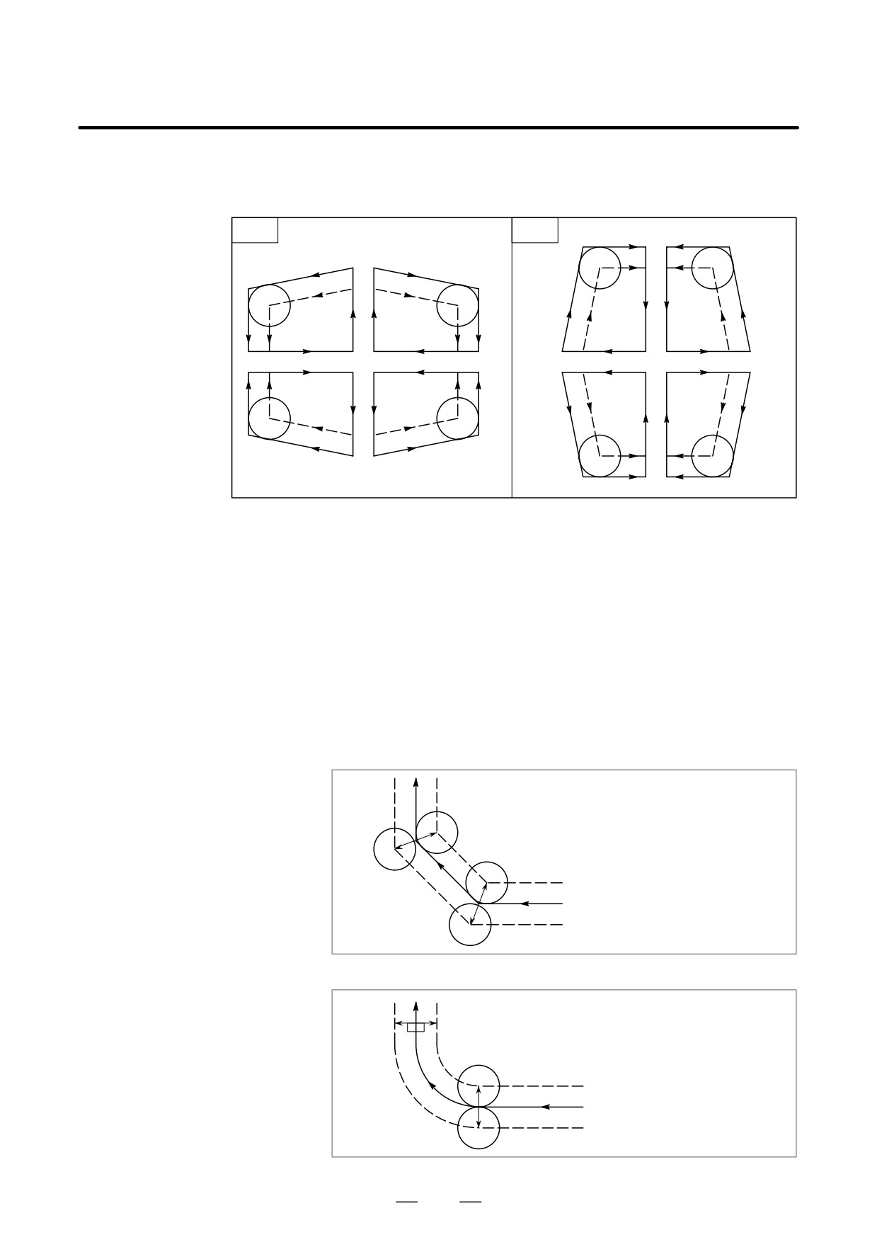
2. Direction of the offset
The offset direction is indicated in the figure below regardless of the
G41/G42 mode.
G90
G94
D Tool nose radius
When one of following cycles is specified, the cycle deviates by a tool
compensation with G71
nose radius compensation vector. During the cycle, no intersection
to G76 or G78
calculation is performed.
G71 (Stock removal in turning or traverse grinding cycle)
G72 (Stock removal in facing or traverse direct constant-dimension
grinding cycle)
G73 (Pattern repeating or Oscillation grinding cycle)
G74 (End face peck drilling)
G75 (Outer diameter/internal diameter drilling)
G76 (Multiple threading cycle)
G78 (Threading cycle)
D Tool nose radius
Movement after after compensation is shown below.
compensation when
chamfering is performed
(G42)
Programmed path
(G41)
D Tool nose radius
Movement after compensation is shown below.
compensation when a
corner arc is inserted
(G42)
Programmed path
(G41)
240
B-63524EN/01
PROGRAMMING
14. COMPENSATION FUNCTION
D Tool nose radius
In this case, tool nose radius compensation is not performed.
compensation when the
block is specified from
the MDI
241
14. COMPENSATION FUNCTION
PROGRAMMING
B-63524EN/01
This section provides a detailed explanation of the movement of the tool
14.3
for tool nose radius compensation outlined in Section 14.2.
DETAILS OF TOOL
This section consists of the following subsections:
NOSE RADIUS
COMPENSATION
14.3.1
General
14.3.2
Tool Movement in Start-up
14.3.3
Tool Movement in Offset Mode
14.3.4
Tool Movement in Offset Mode Cancel
14.3.5
Interference Check
14.3.6
Overcutting by Tool Nose Radius Compensation
14.3.7
Correction in Chamfering and Corner Arcs
14.3.8
Input Command from MDI
14.3.9
General Precautions for Offset Operations
14.3.10 G53, G28, G30, and G30.1 Commands in Tool-tip Radius
Compensation Mode
14.3.1
General
D Tool nose radius center
The tool nose radius center offset vector is a two dimensional vector equal
offset vector
to the offset value specified in a T code, and the is calculated in the CNC.
Its dimension changes block by block according to tool movement.
This offset vector (simply called vector herein after) is internally crated
by the control unit as required for proper offsetting and to calculate a tool
path with exact offset (by tool nose radius) from the programmed path.
This vector is deleted by resetting.
The vector always accompanies the tool as the tool advances.
Proper understanding of vector is essential to accurate programming.
Read the description below on how vectors are created carefully.
D G40, G41, G42
G40, G41 or G42 is used to delete or generate vectors.
These codes are used together with G00, G01, G02, G03 or G33 to specify
a mode for tool motion (Offsetting).
G code
Function
Workpiece position
G40
Tool nose radius compensation cancel
Neither
G41
Left offset along tool path
Right
G42
Right offset along tool path
Left
G41 and G42 specify an off mode, while G40 specifies cancellation of the
offset.
D Cancel mode
The system enters the cancel mode immediately after the power is turned
on, when the RESET button on the MDI is pushed or a program is forced
to end by executing M02 or M30. (the system may not enter the cancel
mode depending on the machine tool.) In the cancel mode, the vector is
set to zero, and the path of the center of tool nose coincides with the
programmed, path. A program must end in cancel mode. If it ends in the
offset mode, the tool cannot be positioned at the end point, and the tool
stops at a location the vector length away from the end point.
242
B-63524EN/01
PROGRAMMING
14. COMPENSATION FUNCTION
D Start-up
When a block which satisfies all the following conditions is executed in
cancel mode, the system enters the offset mode. Control during this
operation is called start-up.
D G41 or G42 is contained in the block, or has been specified to set the
system enters the offset mode. Control during this operation is called
start-up.
D The offset number for tool nose radius compensation is not 00.
D X or Z moves is specified in the block and the move distance is not
zero.
A circular command (G02 or G03) is not allowed in start-up.
If specified, P/S alarm (PS34) will occur. Two blocks are read in during
start- up. The first block is executed, and the second block is entered into
the tool nose radius compensation buffer. In the single block mode, two
blocks are read and the first block is executed, then the machine stops.
In subsequent operations, two blocks are read in advance, so the CNC has
the block currently being executed, and the next two blocks.
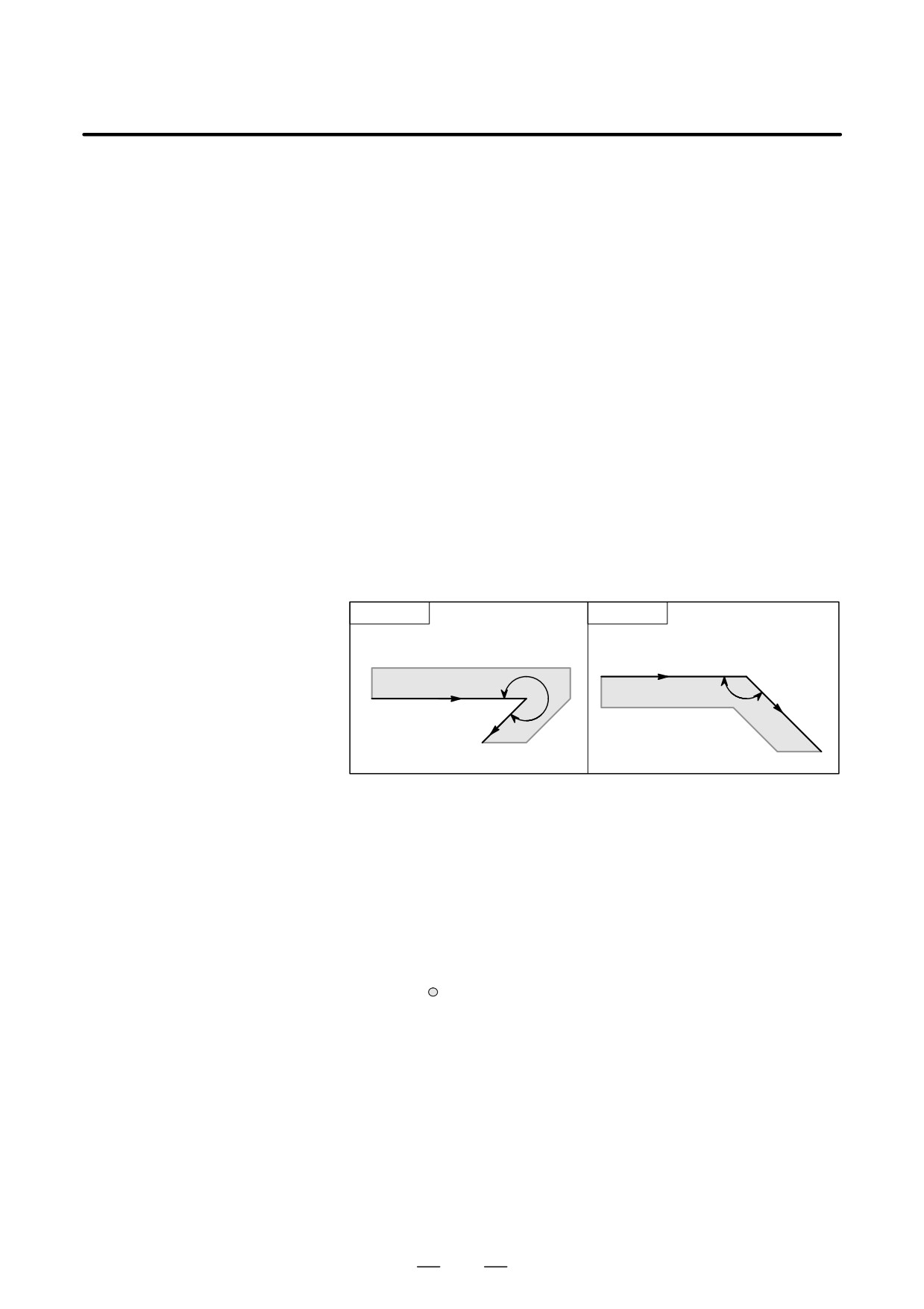
D Inner side and outer side
When an angle of intersection created by tool paths specified with move
commands for two blocks is over 180°, it is referred to as “inner side.”
When the angle is between 0° and 180°, it is referred to as “outer side.”
Inner side
Outer side
Programmed path
Workpiece
α
α
Workpiece
Programmed path
180°xα
0°xα<180°
D Meaning of symbols
The following symbols are used in subsequent figures:
- S indicates a position at which a single block is executed once.
- SS indicates a position at which a single block is executed twice.
- SSS indicates a position at which a single block is executed three times.
- L indicates that the tool moves along a straight line.
- C indicates that the tool moves along an arc.
- r indicates the tool nose radius compensation value.
- An intersection is a position at which the programmed paths of two
blocks intersect with each other after they are shifted by r.
- indicates the center of the tool nose radius.
243
14. COMPENSATION FUNCTION
PROGRAMMING
B-63524EN/01
14.3.2
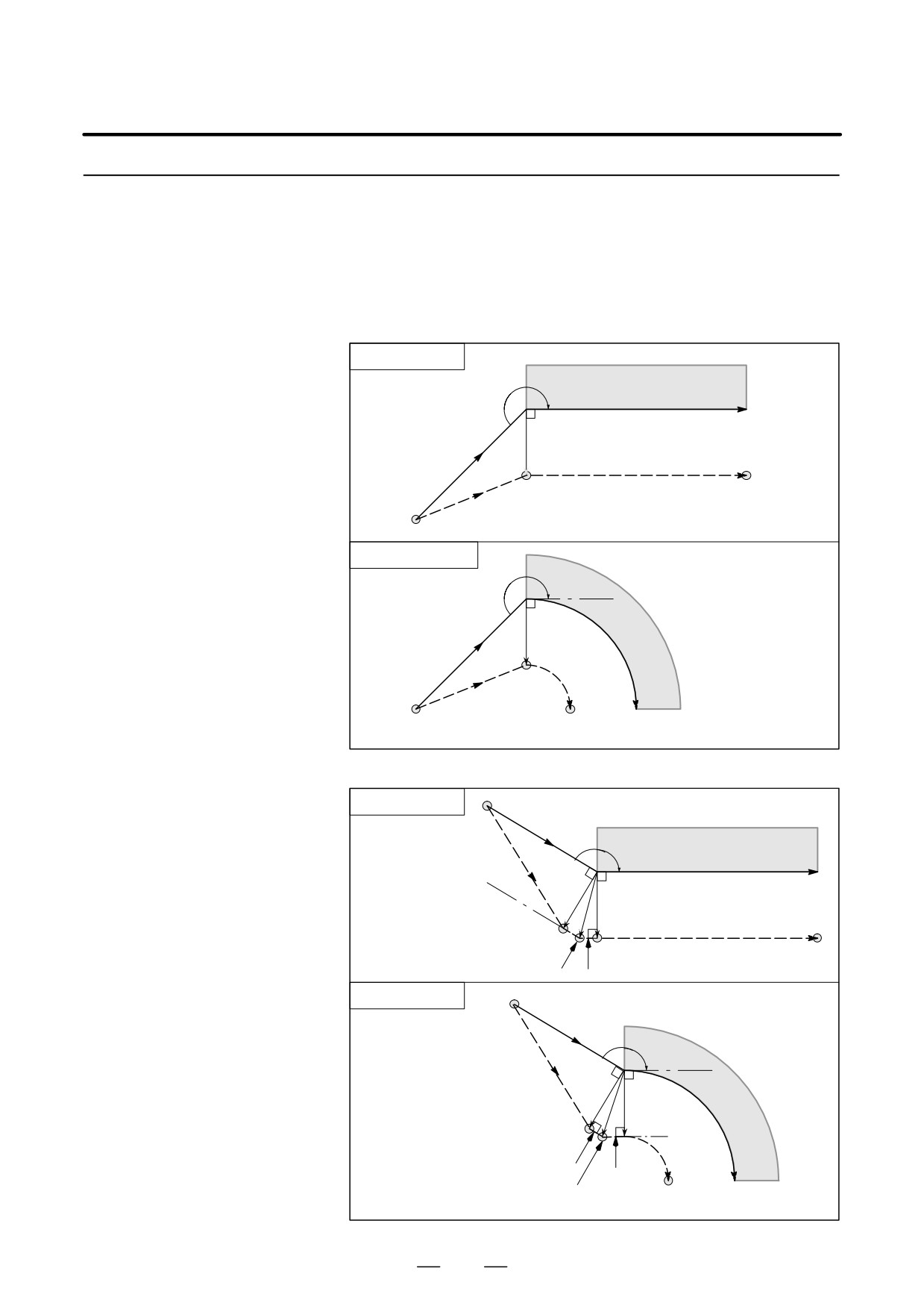
When the offset cancel mode is changed to offset mode, the tool moves
as illustrated below (start-up):
Tool Movement in
Start-up
Explanations
D Tool movement around
an inner side of a corner
Linear→Linear
(180°xα)
Workpiece
α
Programmed path
r
G42
S
L
Tool nose radius center path
L
Start position
Linear→Circular
α
r
G42
Work-
piece
S
C
L
Tool nose radius
Programmed path
Start position
center path
D Tool movement around
the outside of a corner at
Linear→Linear
Start position
an obtuse angle
G42
(90°xα<180°)
α
Workpiece
L
Programmed path
r
r
S
L
Tool nose radius center path
Intersection
L
Linear→Circular
Start position
G42
α
L
r
r
Work-
S
piece
C
L
L
Intersection
Tool nose radius
Programmed path
center path
244

B-63524EN/01
PROGRAMMING
14. COMPENSATION FUNCTION
D Tool movement around
the outside of an acute
Linear→Linear
Start position
angle (α<90°)
L
S
G42
Workpiece
r
α
L
Programmed path
r
L
Tool nose radius center path
L
L
Linear→Circular
Start position
L
S
G42
r
α
L
r
L
Work-
L
C
piece
Tool nose radius
center path
Programmed path
D Tool movement around
the outside linear→linear
S
Tool nose radius center path
at an acute angle less
L
than 1 degree
L
(α<1°)
r
Programmed path
G41
G41
Start position
Less than 1 deg
D A block without tool
If the command is specified at start-up, the offset vector is not created.
movement specified at
G91 G40 … ;
start-up
:
SS
N6 U100.0 W100.0 ;
N7
N7 G41 U0 ;
N8 U-100.0 ;
N9 U-100.0 W100.0 ;
N6
S
N8
r
Tool nose radius
center path
N9
Programmed path
NOTE
For the definition of blocks that do not move the tool, see
Subsec. II-14.3.3.
245
14. COMPENSATION FUNCTION
PROGRAMMING
B-63524EN/01
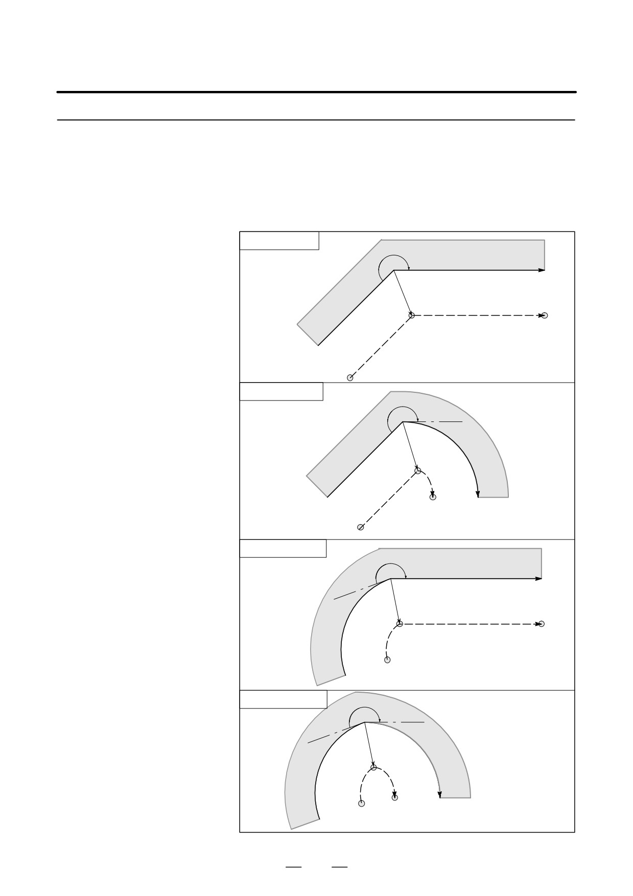
14.3.3
In the offset mode, the tool moves as illustrated below:
Tool Movement in
Offset Mode
Explanations
D Tool movement around
the inside of a corner
Linear→Linear
(180°xα)
α
Workpiece
Programmed path
Tool nose radius center path
S
L
Intersection
L
Linear→Circular
α
Work-
piece
Intersection
C
S
L
Tool nose radius
Programmed path
center path
Circular→Linear
α
Workpiece
Programmed path
Tool nose radius center path
S
L
C
Intersection
Circular→Circular
α
Work-
Intersection
piece
S
C
C
Programmed path
Tool nose radius
center path
246
B-63524EN/01
PROGRAMMING
14. COMPENSATION FUNCTION
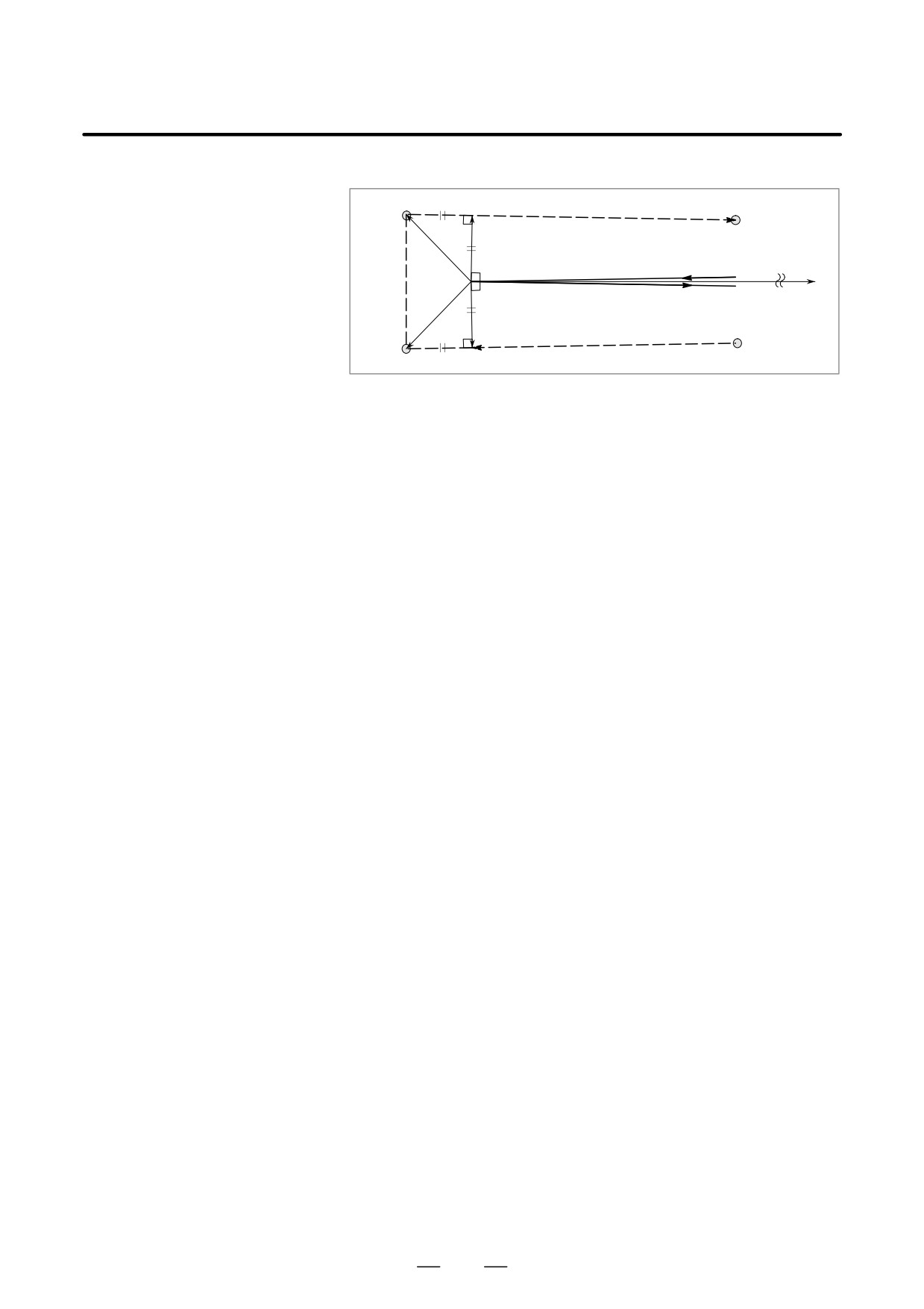
D Tool movement around
the inside (α<1°) with an
Intersection
abnormally long vector,
linear → linear
r
Tool nose radius center path
Programmed path
r
r
S
Intersection
Also in case of arc to straight line, straight line to arc and arc to arc, the
reader should infer in the same procedure.
247
14. COMPENSATION FUNCTION
PROGRAMMING
B-63524EN/01
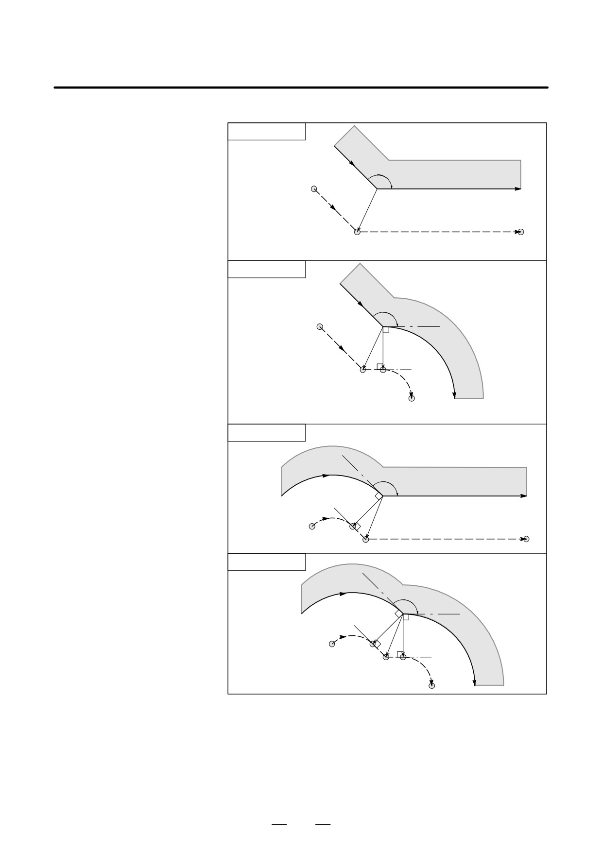
D Tool movement around
the outside corner at an
Linear→Linear
obtuse angle
(90°xα<180°)
α
Workpiece
L
Programmed path
Tool nose radius center path
S
Intersection
L
Linear→Circular
α
L
r
Work-
piece
L
S
C
Intersection
Programmed path
Tool nose radius
center path
Circular→Linear
α
Workpiece
Programmed path
r
C
Tool nose radius center path
IntersectionSL
L
Circular→Circular
α
Programmed path
r
Work-
r
piece
C
Tool nose radius
SL
center path
L
Intersection
C
248