FANUC Series 0i-MC. OPERATOR’S MANUAL - page 29
B. LIST OF FUNCTIONS AND
TAPE FORMAT
APPENDIX
B-64124EN/01
LIST OF FUNCTIONS AND TAPE FORMAT
B
Some functions cannot be added as options depending on the model.
In the tables below,
I
:presents a combination of arbitrary
axis
addresses using X,Y,Z,A,B and C (such as X_Y_Z_A_).
x = 1st basic axis (X usually)
y = 2nd basic axis (Y usually)
z = 3rd basic axis (Z usually)
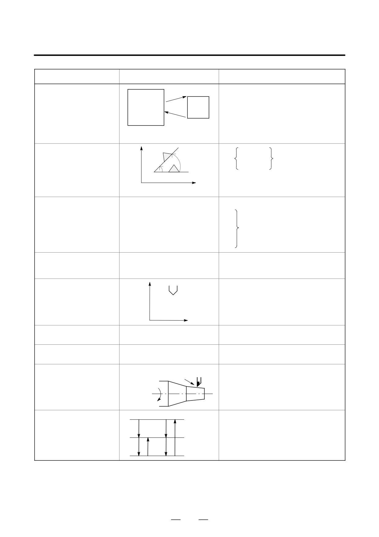
Functions
Illustration
Tape format
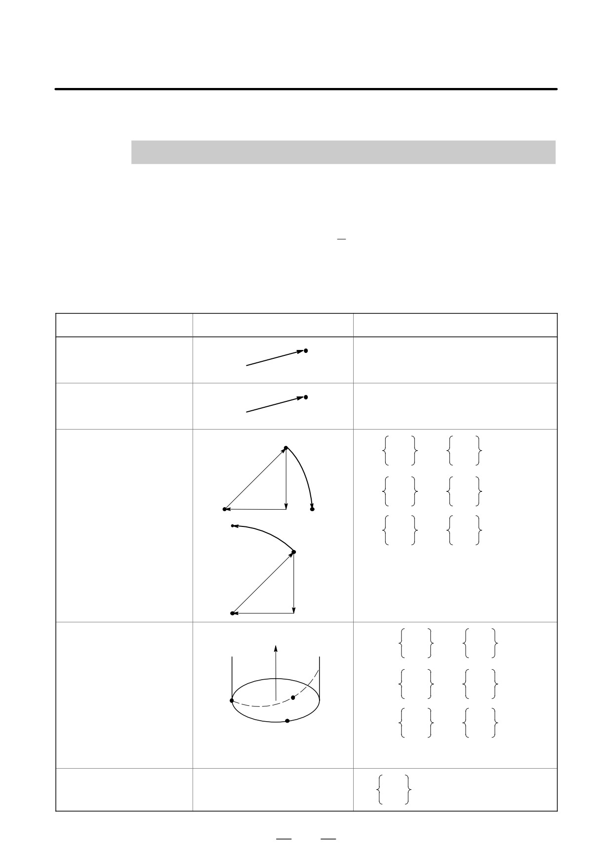
Positioning (G00)
I
P
G00
I
P
_ ;
Start point
Linear interpolation (G01)
I
P
G01
I
P
_ F_;
Start point
Circular interpolation
Start point
G02
R_
(G02, G03)
G17
X_ Y_
F_ ;
G03
I_ J_
G02
R
J
G02
R_
G18
X_ Z_
F_ ;
G03
I_ K_
I
(x, y)
G02
R_
(x,
y)
G03
G19
Y_ Z_
F_ ;
G03
J_ K_
Start
point
R
J
I
Helical interpolation
Z
G02
R_
(G02, G03)
G17
X_ Y_
α_ F_ ;
G03
I_ J_
G02
R_
G18
X_ Z_
α_ F_ ;
G03
I_ K_
(xyz)
G02
R_
Start
G19
Y_ Z_
α_ F_ ;
(x, y)
J_ K_
point
G03
α : Any axis other than circular
(In case of X-Y plane)
interpolation axes.
Dwell (G04)
X_
G04
;
P_
828
B. LIST OF FUNCTIONS AND
B-64124EN/01
APPENDIX
TAPE FORMAT
Functions
Illustration
Tape format
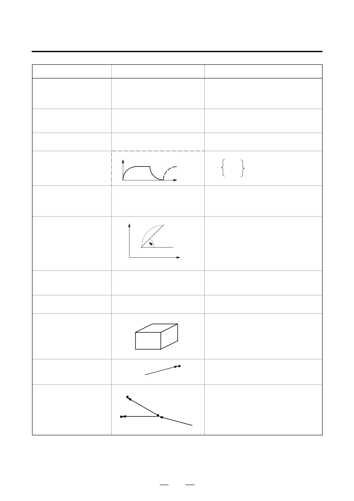
AI advanced preview control
G05.1 Q1; AI advanced preview control
(G05.1)
mode on
G05.1 Q0 ; AI advanced preview control
mode off
Cylindrical interpolation
G07.1 IP_r_; Cylindrical interpolation mode
(G07.1)
G07.1 IP0 ; Cylindrical interpolation mode cancel
r: Radius of cylinder
Advanced preview control (G08)
G08 P1: Advanced preview control mode on
G08 P0: Advanced preview control mode off
Exact stop (G09)
Velocity
G01
IP_;
G09
G02
G03
Time
Change of offset value by
G10 L10 P_R_;(Geomerty offset value/H)
program (G10)
G10 L11 P_R_;(Wear offset value/H)
G10 L12 P_R_;(Geomerty offset value/D)
G10 L13 P_R_;(Wear offset value/D)
Polar coordinate (G15, G16)
Local coordinate
G17 G16 Xp_ Yp_ . ;
Yp
Yp
G18 G16 Zp_ Xp_ . ;
G19 G16 Yp_ Zp_ . ;
Xp
G15 ; Cancel
(x y)
Xp
Work coordinate system
Plane selection
G17 ;
(G17, G18, G19)
G18 ;
G19 ;
Inch/millimeter
G20 : Inch input
conversion (G20, G21)
G21 : Millimeter input
Stored stroke check
(XYZ)
G22 X_Y_Z_I_J_K_;
(G22, G23)
G23 Cancel;
(IJK)
Reference position return
I
P
G27
I
P
_ ;
check (G27)
Start point
Reference position return
Reference position
(G28)
G27
I
P_ ;
(G28)
2nd, reference position return
Intermediateposition
(G30)
I
P
2nd reference
position (G30)
Start point
829
B. LIST OF FUNCTIONS AND
TAPE FORMAT
APPENDIX
B-64124EN/01
Functions
Illustration
Tape format
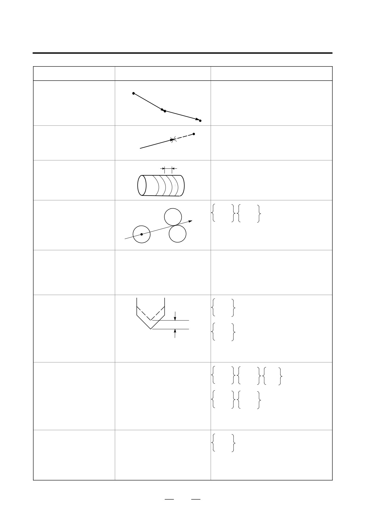
Return from reference
Reference position
G29
I
P_ ;
position to start point (G29)
I
P
Intermediate position
Skip function (G31)
I
P
G31
I
P_ F_;
Skip signal
Start point
Thread cutting (G33)
F
G33
I
P_ F_;
F : lead
Cutter compensation C
G41
G17
G41
(G40 - G42)
G18
D_ ;
ÇÇÇ
G42
G19
G40
ÇÇÇ
ÇÇ
ÇÇÇ
D : Tool offset
G40 : Cancel
ÇÇ
Tool
ÇÇÇG42
Normal direction control
G41.1 (G151)
(G40.1, G41.1, G42.1)
Normal direction control left
(G150, G151, G152)
G42.1 (G152)
Normal direction control right
G40.1 (G150)
Normal direction control cancel
Tool length offset A
G43
(G43, G44, G49)
Offset
Z_ H_ ;
G44
Z
G43
H_ ;
G44
H : Tool offset
G49 : Cancel
Tool length offset B
G17
G43
Z_
(G43, G44, G49)
G18
Y_
H_ ;
G44
G19
X_
G17
G43
G18
H_ ;
G19
G44
H : Tool offset
G49 : Cancel
Tool length offset C
G43
(G43, G44, G49)
a_ H_ ;
G44
a : An optional address of one axis
H : Tool offset number
G49 : Cancel
830
B. LIST OF FUNCTIONS AND
B-64124EN/01
APPENDIX
TAPE FORMAT
Functions
Illustration
Tape format
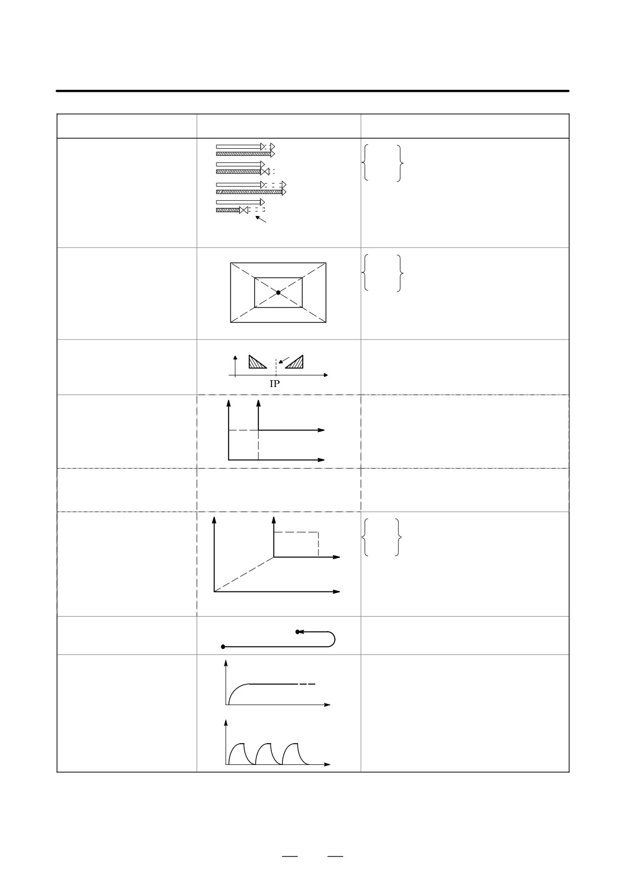
Tool offset (G45 - G48)
G45
Increase
G46
I
P_ D_;
IP
Decrease
G47
2 times
G48
increase
D : Tool offset number
IP
2 times
decrease
Compensation
value
Scaling (G50, G51)
P4
P3
G45
P4’
P3’
G46
I
P_ D_;
G47
I
P
G48
D : Tool offset number
P1’
P2’
P1
P2
Programmable mirror
Mirror
G51.1 IP _ ;
image (G50.1, G51.1)
G50.1 ; .
Cancel
Setting of local
G52
I
P_ ;
Local coordinate
coordinate system
x
system
(G52)
I
P
Work coordinate
y
system
Command in machine
G53
I
P_ ;
coordinate system
(G53)
Selection of work
G54
Work zero
I
P
coordinate system
:
I
P_ ;
(G54 - G59)
point
offset
G59
Work coordinate
system
Machine coordinate system
Single direction
I
P
G60
I
P_ ;
positioning (G60)
Cutting mode (G64)
G64_ ; Cutting mode
v
Exact stop mode (G61)
G61_ ; Exact stop mode
Tapping mode (G63)
G63_ ; Tapping mode
G64
G62_ ; Automatic corner override
t
Automatic corner override
(G62)
v
G61
t
831
B. LIST OF FUNCTIONS AND
TAPE FORMAT
APPENDIX
B-64124EN/01
Functions
Illustration
Tape format
Custom macro
Macro
One-shot call
(G65, G66, G67)
G65 P_ L_
O_ ;
<Argument assignment> ;
G65 P_ L_ ;
P : Program No.
M99 ;
L : Number of repeatition
Modal call
G66 P_L_
<Argument
G67 ; Cancel
assignment>;
Coordinate system rotation
Y
G17 X_ Y_
(G68, G69)
G68
R α ;
G18 Z_ X_
a
G19 Y_ Z_
(x y)
G69 ; Cancel
X
(In case of X-Y plane)
Canned cycles
Refer to II.13. FUNCTIONS TO
G80 ; Cancel
(G73, G74, G76, G80 - G89)
SIMPLIFY PROGRAMMING
G73
G74
G76
X_ Y_ Z_ P_ Q_ R_ F_ K_ ;
G81
:
G89
Absolute/incremental
G90_ ; Absolute command
programming (G90/G91)
G91_ ; Incremental command
G90_ G91_ ; Combined use
Change of workpiece
G92
I
P_ ; Change of workpiece coordinate
coordinate system (G92)
ÇÇ
system
I
Maximum spindle speed
Ç
G92S_ ; Maximum spindle speed clump
clump (G92)
Workpiece coordinate
G92.1
I
P
0;
system preset (G92.1)
Feed per minute, Feed
mm/min
inch/min
G94 F_ ; Feed per minute
per revolution (G94, G95)
mm/rev
inch/rev
G95 F_ ; Feed per revolution
Constant surface speed
Surface speed
G96 S_ ; Starts constant surface speed control
control (G96, G97)
(m/min or feet/min)
(Surface speed command)
G97 S_ ; Constant surface speed is cancelled
Spindle speed
N (min-1)
(Maximum spindle speed command)
Initial point return / R point
G98
G98_ ;
Initial
return (G98, G99)
G99_ ;
level
G99
R level
Z point
832
B-64124EN/01
APPENDIX
C. RANGE OF COMMAND VALUE
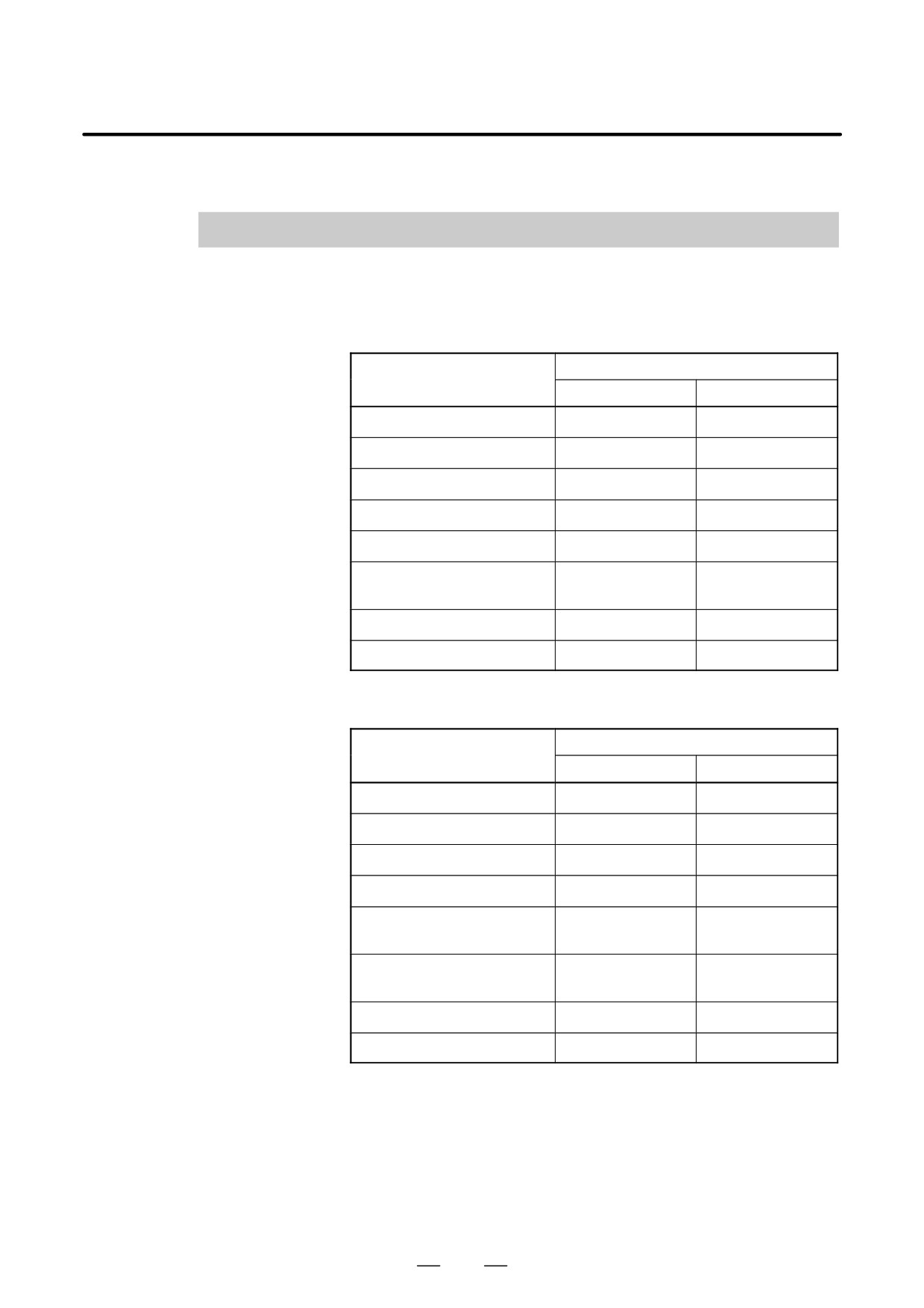
RANGE OF COMMAND VALUE
C
Linear axis
D In case of millimeter
Increment system
input, feed screw is
IS-B
IS-C
millimeter
Least input increment
0.001 mm
0.0001 mm
Least command increment
0.001 mm
0.0001 mm
Max. programmable dimension
±99999.999 mm
±9999.9999 mm
Max. rapid traverse Note
240000 mm/min
100000 mm/min
Feedrate range Note
1 to 240000 mm/min
1 to 100000 mm/min
Incremental feed
0.001, 0.01, 0.1,
0.0001, 0.001, 0.01,
1 mm/step
0.1 mm/step
Tool compensation
0 to ±999.999 mm
0 to ±999.9999 mm
Dwell time
0 to 99999.999 sec
0 to 99999.999 sec
D In case of inch input,
Increment system
feed screw is millimeter
IS-B
IS-C
Least input increment
0.0001 inch
0.00001 inch
Least command increment
0.001 mm
0.0001 mm
Max. programmable dimension
±9999.9999 inch
±393.70078 inch
Max. rapid traverse Note
240000 mm/min
100000 mm/min
Feedrate range Note
0.01 to 9600
0.01 to 4000
inch/min
inch/min
Incremental feed
0.0001, 0.001, 0.01,
0.00001, 0.0001,
0.1 inch/step
0.001, 0.01 inch/step
Tool compensation
0 to ±99.9999 inch
0 to ±99.9999 inch
Dwell time
0 to 99999.999 sec
0 to 9999.9999 sec
833
C. RANGE OF COMMAND VALUE
APPENDIX
B-64124EN/01
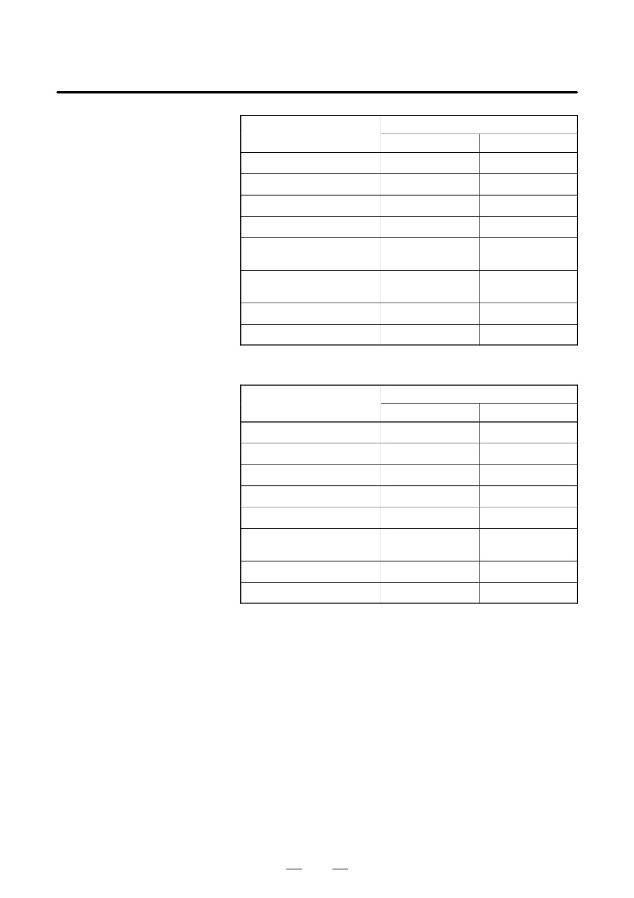
D In case of inch input,
Increment system
feed screw is inch
IS-B
IS-C
Least input increment
0.0001 inch
0.00001 inch
Least command increment
0.0001 inch
0.00001 inch
Max. programmable dimension
±9999.9999 inch
±9999.9999 inch
Max. rapid traverse Note
9600 inch/min
4000 inch/min
Feedrate range Note
0.01 to 9600
0.01 to 4000
inch/min
inch/min
Incremental feed
0.0001, 0.001, 0.01,
0.00001, 0.0001,
0.1 inch/step
0.001, 0.01 inch/step
Tool compensation
0 to ±99.9999 inch
0 to ±99.9999 inch
Dwell time
0 to 99999.999 sec
0 to 9999.9999 sec
D In case of millimeter
Increment system
input, feed screw is inch
IS-B
IS-C
Least input increment
0.001 mm
0.0001 mm
Least command increment
0.0001 inch
0.00001 inch
Max. programmable dimension
±99999.999 mm
±9999.9999 mm
Max. rapid traverse Note
9600 inch/min
4000 inch/min
Feedrate range Note
1 to 240000 mm/min
1 to 100000 mm/min
Incremental feed
0.001, 0.01, 0.1, 1
0.0001, 0.001, 0.01,
mm/step
0.1 mm/step
Tool compensation
0 to ±999.999 mm
0 to ±999.9999 mm
Dwell time
0 to 99999.999 sec
0 to 9999.9999 sec
834
B-64124EN/01
APPENDIX
C. RANGE OF COMMAND VALUE
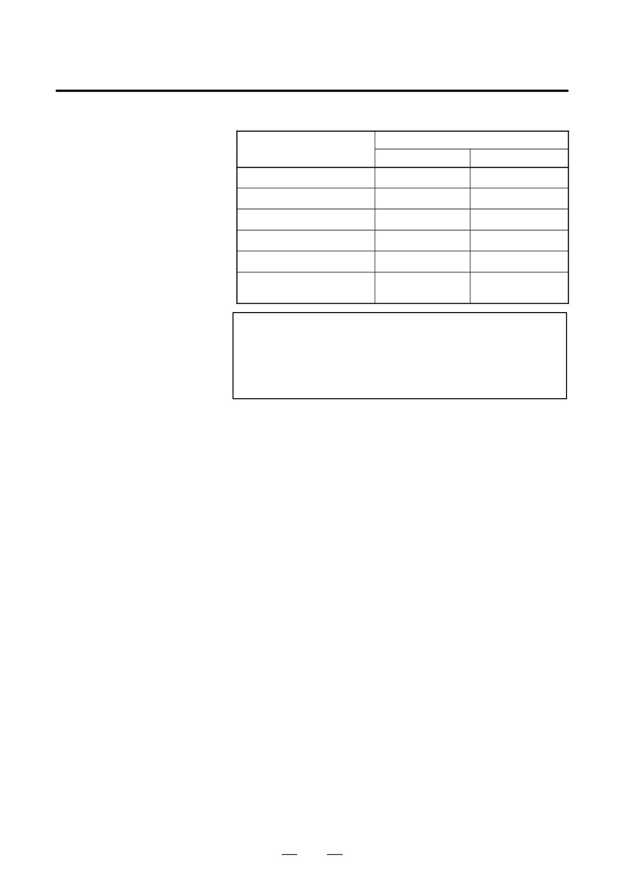
Rotation axis
Increment system
IS-B
IS-C
Least input increment
0.001 deg
0.0001 deg
Least command increment
0.001 deg
0.0001 deg
Max. programmable dimension
±99999.999 deg
±9999.9999 deg
Max. rapid traverse Note
240000 deg/min
100000 deg/min
Feedrate range Note
1 to 240000 deg/min
1 to 100000 deg/min
Incremental feed
0.001, 0.01, 0.1,
0.0001, 0.001, 0.01,
1 deg/step
0.1 deg/step
NOTE
The feedrate range shown above are limitations depending
on CNC interpolation capacity. As a whole system,
limitations depending on servo system must also be
considered.
835
B-64124EN/01
APPENDIX
D. NOMOGRAPHS
D.1
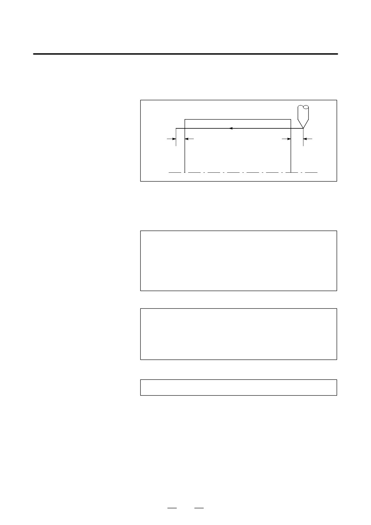
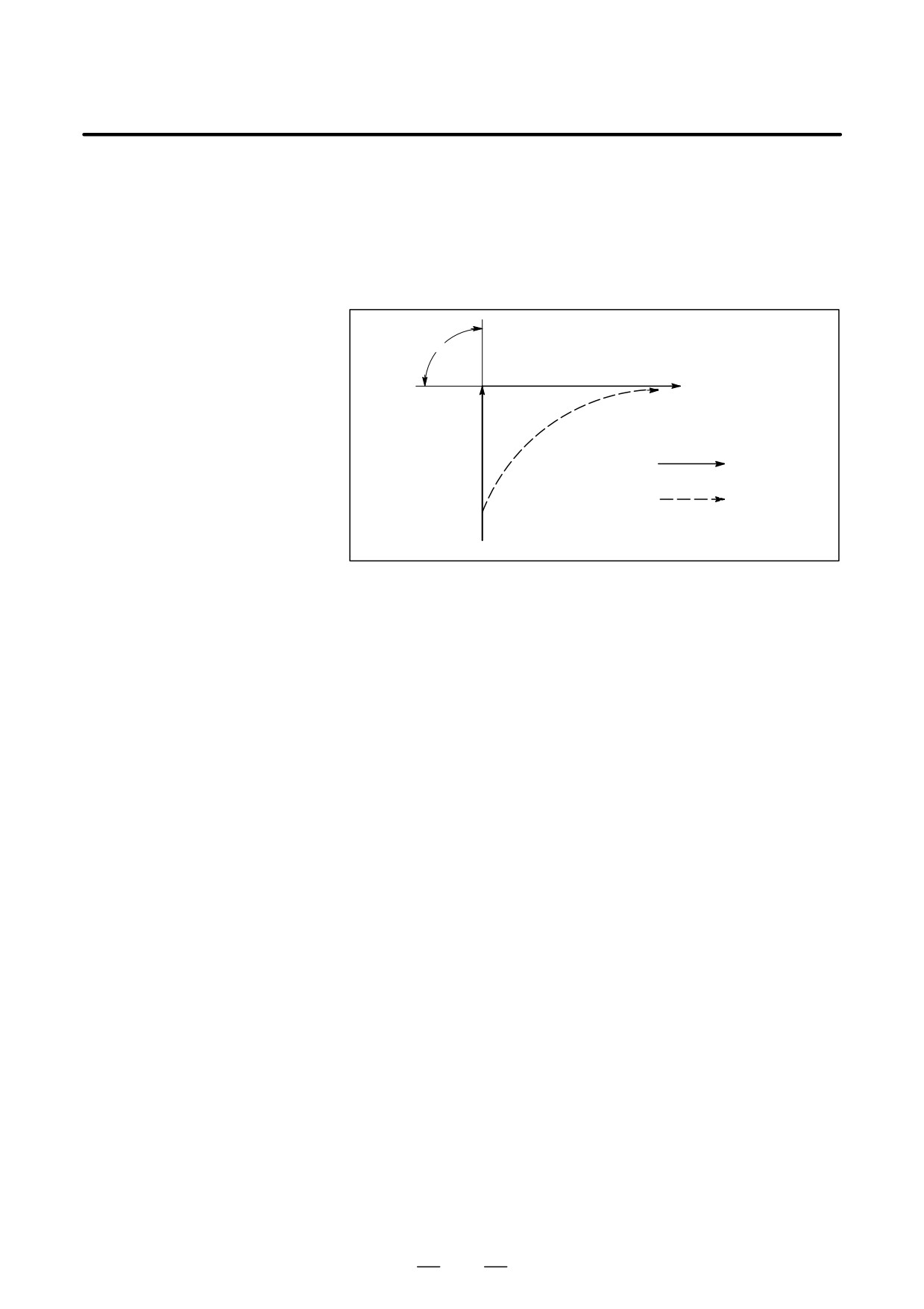
The leads of a thread are generally incorrect in δ1 and δ2, as shown in Fig.
D.1 (a), due to automatic acceleration and deceleration.
INCORRECT
Thus distance allowances must be made to the extent of δ1 and δ2 in the
THREADED LENGTH
program.
δ
2
δ
1
Fig. D.1 (a) Incorrect thread position
Explanations
D How to determine δ2
d2 + T1V
(mm)
(1)
1
V+
60RL
T1
: Time constant of servo system (sec)
V
: Cutting speed (mm/sec)
Time constant T1 (sec) of
R
: Spindle speed (min-1)
the servo system: Usually
L
: Thread feed (mm)
0.033 s.
D How to determine δ1
t
d1 + {t-T1 ) T1 exp(-
)}V
(2)
T1
t
a + exp(-
)
(3)
T1
Time constant T1 (sec) of
T1
: Time constant of servo system (sec)
the servo system: Usually
V
: Cutting speed (mm/sec)
0.033 s.
The lead at the beginning of thread cutting is shorter than the specified
lead L, and the allowable lead error is ∆L. Then as follows.
a+DL
L
When the value of HαI is determined, the time lapse until the thread
accuracy is attained. The time HtI is substituted in (2) to determine δ1:
Constants V and T1 are determined in the same way as for δ2. Since the
calculation of δ1 is rather complex, a nomography is provided on the
following pages.
837
D. NOMOGRAPHS
APPENDIX
B-64124EN/01
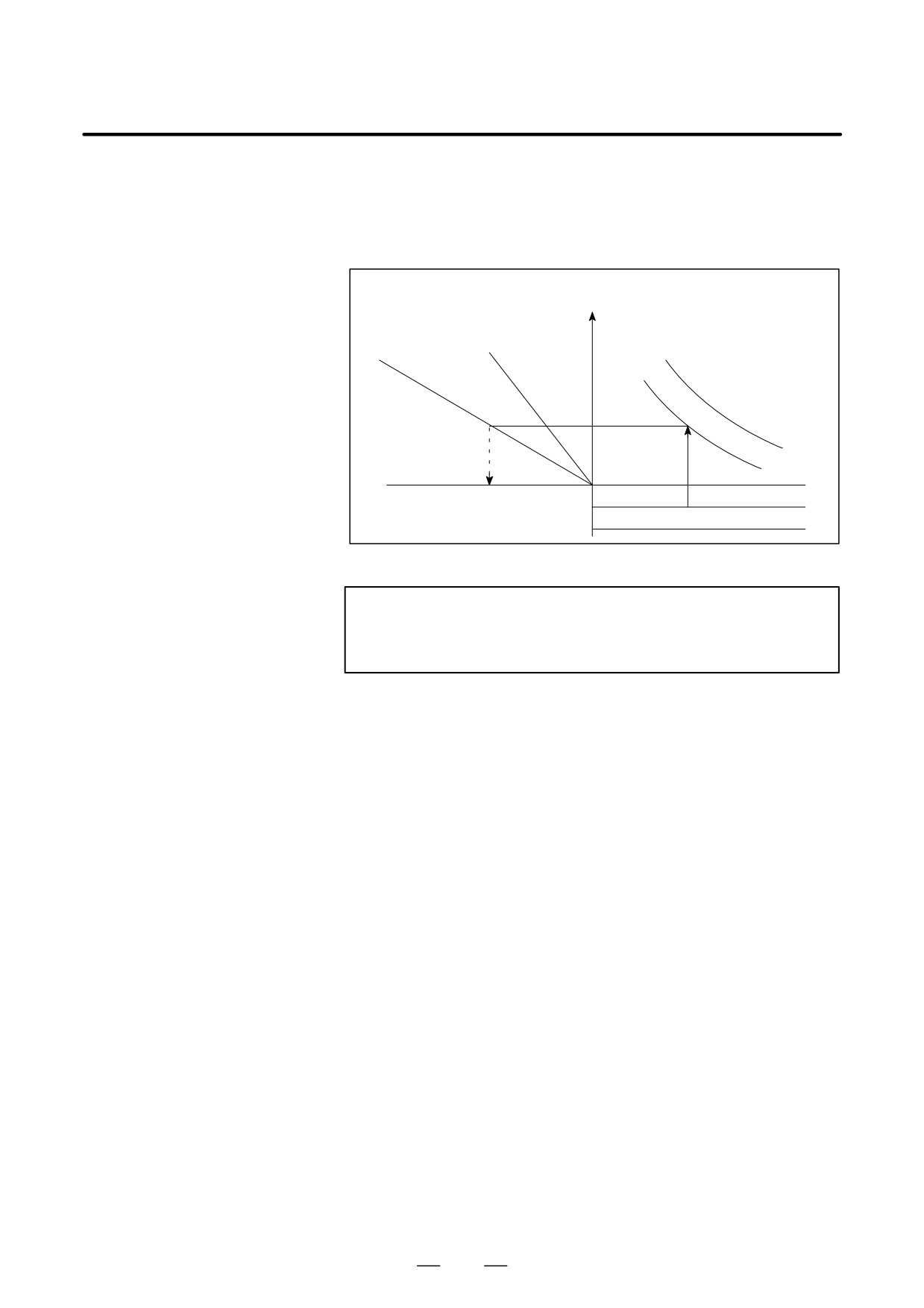
First specify the class and the lead of a thread. The thread accuracy, α,
D How to use nomograph
will be obtained at (1), and depending on the time constant of cutting feed
acceleration/ deceleration, the δ1 value when V = 10mm / s will be
obtained at (2). Then, depending on the speed of thread cutting, δ1 for
speed other than 10mm/ s can be obtained at (3).
δ1(V=10mm/
sec)
V=20mm/
V=40mm/
sec
sec
Time constant of
servo system
(2)
T1
(3)
(1)
T2
δ1
a
0
L
See the graph in reference later in
the manual for an actual example.
L
Fig. D.1 (b) Nomograph
NOTE
The equations for δ1, and δ2 are for when the acceleration/
deceleration time constant for cutting feed is 0.
838
B-64124EN/01
APPENDIX
D. NOMOGRAPHS
D.2
SIMPLE
CALCULATION OF
INCORRECT THREAD
LENGTH
δ2
δ1
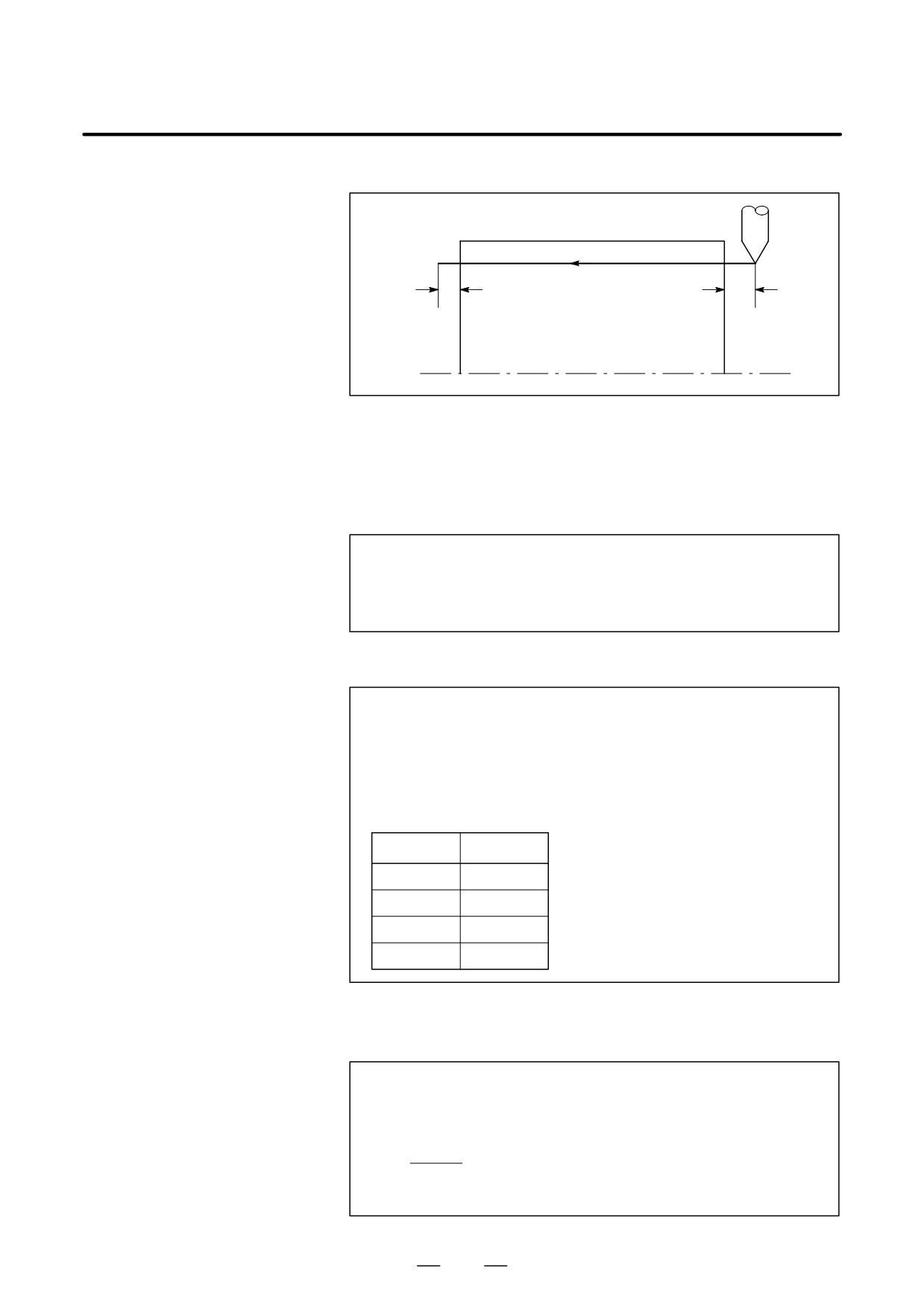
Fig. D.2 (a) Incorrect threaded portion
Explanations
D How to determine δ2
d2 +LR
1800 *
(mm)
R : Spindle speed (min-1)
* When time constant T of the
L : Thread lead (mm)
servo system is 0.033 s.
D How to determine δ1
d1 +LR
(-1-lna)
1800 *
(mm)
+ d2(-1-lna)
(mm)
R : Spindle speed (min-1)
* When time constant T of the
L : Thread lead (mm)
servo system is 0.033 s.
Following a is a permited value of thread.
a
-1-lna
0.005
4.298
0.01
3.605
0.015
3.200
0.02
2.912
Examples
R=350min-1
L=1mm
a=0.01
then
1
d2 +350
+ 0.194
(mm)
1800
d1 + d2
3.605 + 0.701 (mm)
839
D. NOMOGRAPHS
APPENDIX
B-64124EN/01
D Reference
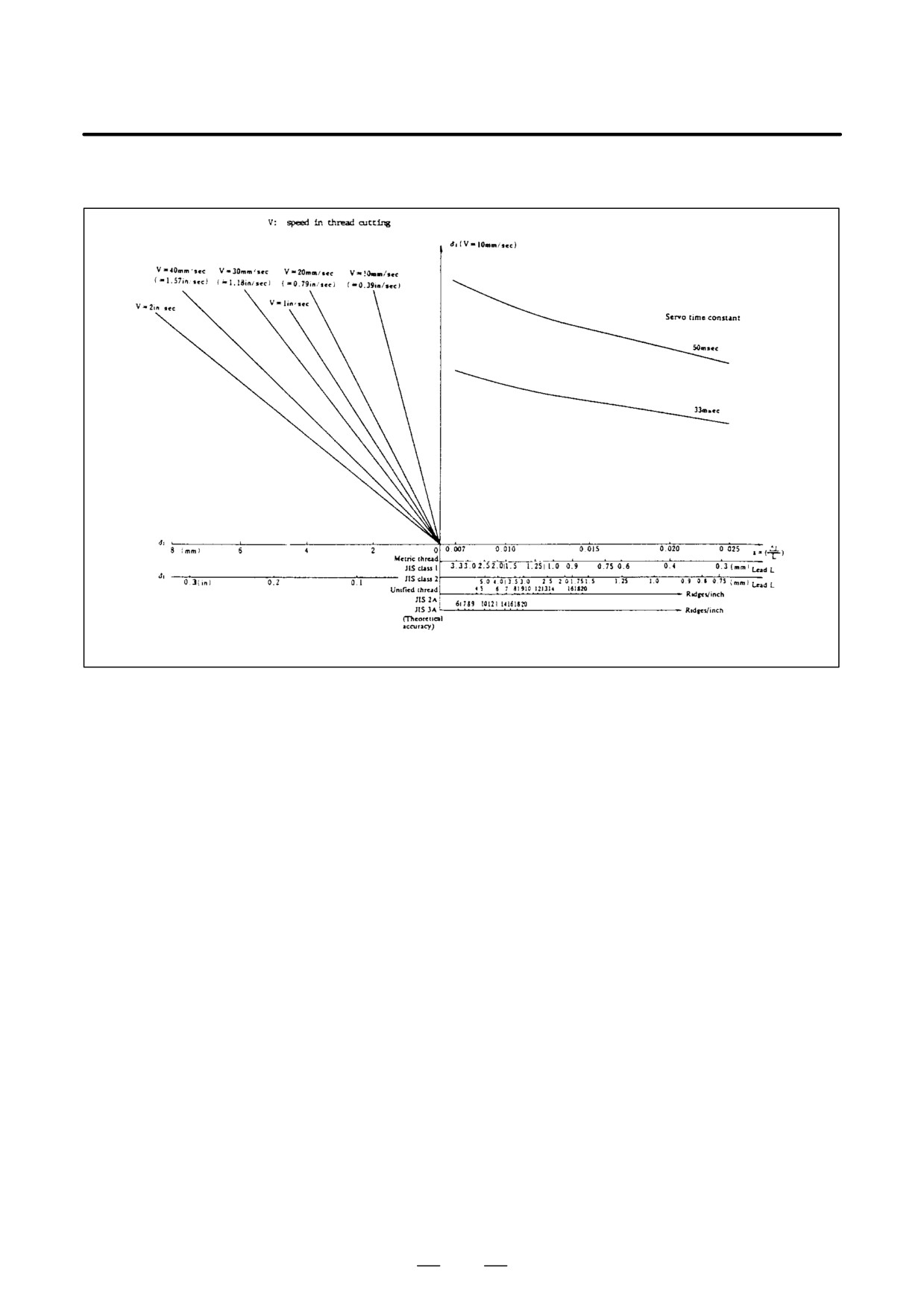
Fig. D.2 (b) Nomograph for obtaining approach distance δ1
840
B-64124EN/01
APPENDIX
D. NOMOGRAPHS
D.3
When servo system delay (by exponential acceleration/deceleration at
cutting or caused by the positioning system when a servo motor is used)
TOOL PATH AT
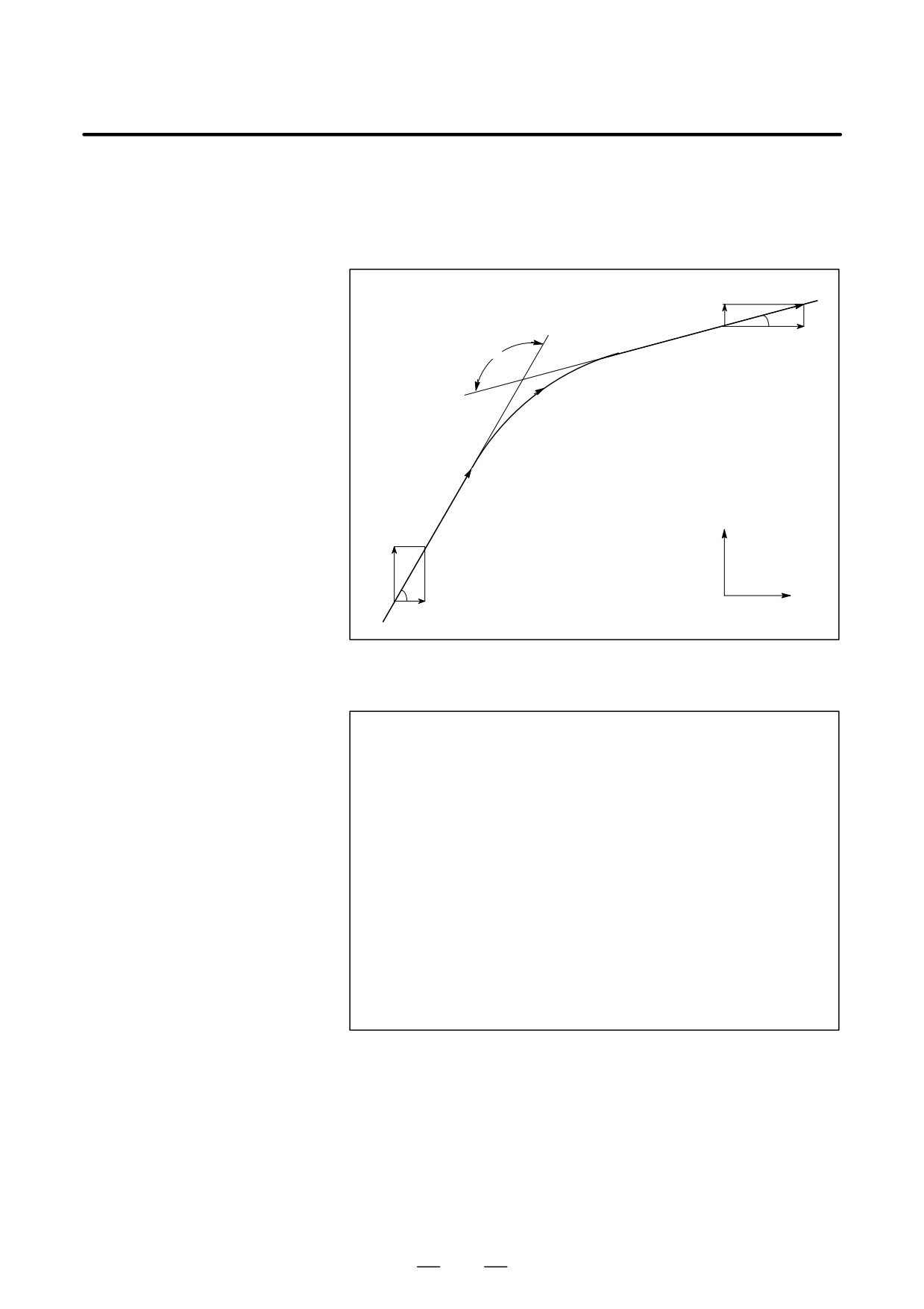
is accompanied by cornering, a slight deviation is produced between the
CORNER
tool path (tool center path) and the programmed path as shown in Fig. D.3
(a).
Time constant T1 of the exponential acceleration/deceleration is fixed to
0.
θ
V2
Programmed path
Tool path
V1
Fig. D.3 (a) Slight deviation between the tool path and
the programmed path
This tool path is determined by the following parameters:
• Feedrate (V1, V2)
• Corner angle (q)
• Exponential acceleration / deceleration time constant (T1) at
cutting (T1 = 0)
• Presence or absence of buffer register.
The above parameters are used to theoretically analyze the tool path and
above tool path is drawn with the parameter which is set as an example.
When actually programming, the above items must be considered and
programming must be performed carefully so that the shape of the
workpiece is within the desired precision.
In other words, when the shape of the workpiece is not within the
theoretical precision, the commands of the next block must not be read
until the specified feedrate becomes zero. The dwell function is then used
to stop the machine for the appropriate period.
841
D. NOMOGRAPHS
APPENDIX
B-64124EN/01
Analysis
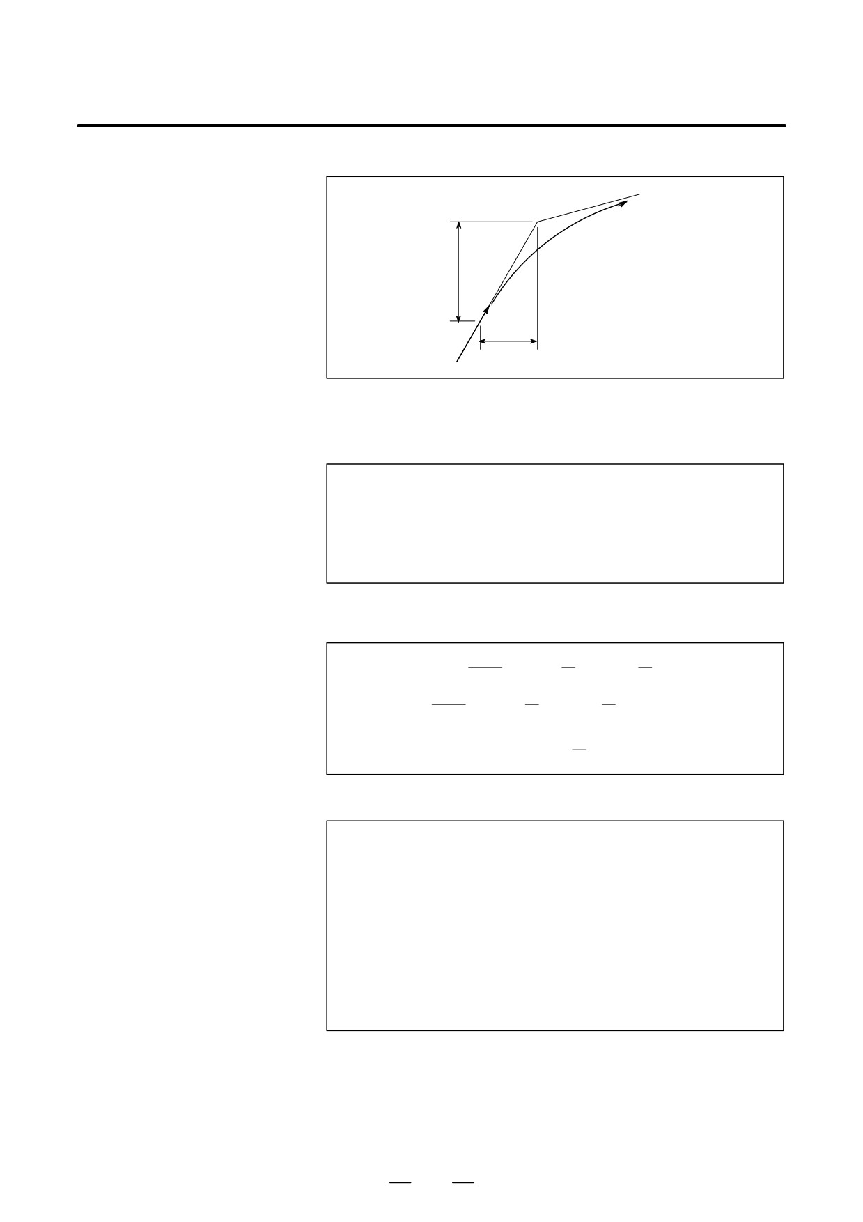
The tool path shown in Fig. D.3 (b) is analyzed based on the following
conditions:
Feedrate is constant at both blocks before and after cornering.
The controller has a buffer register.
(The error differs with the reading
speed of the tape reader, number of characters of the next block, etc.)
V
VY2
φ2
VX2
θ
V
Z
VY1
φ1
0
VX1
X
Fig. D.3 (b) Example of tool path
D Description of conditions
and symbols
VX1 + V cos f1
VY1 + V sin f1
VX2 + V cos f2
VY2 + V sin f2
V
: Feedrate at both blocks before and after cornering
VX1 : X-axis component of feedrate of preceding block
VY1 : Y-axis component of feedrate of preceding block
VX2 : X-axis component of feedrate of following block
VY2 : Y-axis component of feedrate of following block
θ
: Corner angle
φ1
: Angle formed by specified path direction of preceding block
and X-axis
φ2
: Angle formed by specified path direction of following block
and X-axis
842
B-64124EN/01
APPENDIX
D. NOMOGRAPHS
D Initial value calculation
0
Y0
V
X0
Fig. D.3 (c) Initial value
The initial value when cornering begins, that is, the X and Y coordinates
at the end of command distribution by the controller, is determined by the
feedrate and the positioning system time constant of the servo motor.
X0 + VX1(T1 ) T2)
Y0 + VY1(T1 ) T2)
T1:Exponential acceleration / deceleration time constant. (T=0)
T2:Time constant of positioning system (Inverse of position loop gain)
D Analysis of corner tool
The equations below represent the feedrate for the corner section in
path
X-axis direction and Y-axis direction.
VX1
VX(t) + (VX2-VX1)[1-
T1-T2 {T1 exp(
T1)-T2 exp(
T2
VX1
+ VX2[1-
T1-T2 {T1 exp(
T1)-T2 exp(
T2
t
VY(t) +VY1-VY2
{T1 exp(-
)} ) VY2
T1-T2
T1)-T2 exp(-T
2
Therefore, the coordinates of the tool path at time t are calculated from the
following equations:
t
X(t) + ŕ
VX(t)dt-X0
0
t
t
+VX2-VX1
{T12 exp(-
exp(-
)}-VX2(T1 ) T2-t)
T1-T2
T1)-T22
T2
t
Y(t) + ŕ
VY(t)dt-Y0
0
t
t
+VY2-VY1
{T12 exp(-
exp(-
)}-VY2(T1 ) T2-t)
T1-T2
T1)-T22
T2
843
D. NOMOGRAPHS
APPENDIX
B-64124EN/01
D.4
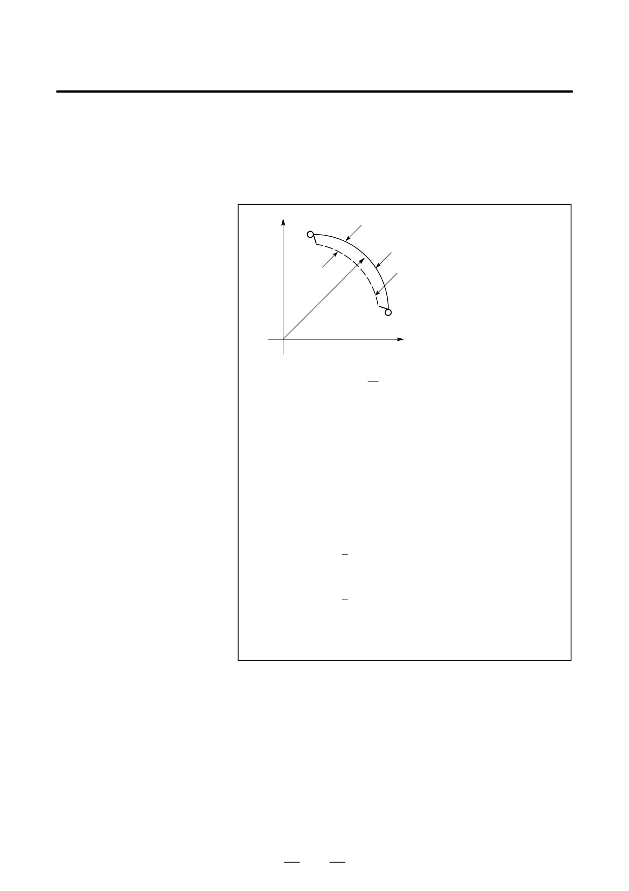
When a servo motor is used, the positioning system causes an error
between input commands and output results. Since the tool advances
RADIUS DIRECTION
along the specified segment, an error is not produced in linear
ERROR AT CIRCLE
interpolation. In circular interpolation, however, radial errors may be
CUTTING
produced, sepecially for circular cutting at high speeds.
This error can be obtained as follows:
X
Dr
Command path
Actual path
r
Z
1
Dr +
(T12 ) T22(1 * a2))V2
(1)
2
r
Dr
: Maximum radius error (mm)
v : Feedrate (mm/s)
r
: Circle radius (mm)
T1
: Exponential acceleration/deceleration time constant (sec)
at cutting (T=0)
T2
: Time constant of positoning system (sec). (Inverse of positon
loop gain)
a
: Feed forward coefficient (%)
In the case of bell-shaped acceleration/deceleration and linear acceleration/
deceleration after cutting feed interpolation, an approximation of this radius
error can be obtained with the following expression:
Linear acceleration/deceleration after cutting feed interpolation
Dr + ǒ 1
24T12 )2T22(1*a2)Ǔ
r
Bell-shaped acceleration/deceleration after cutting feed interpolation
Dr + ǒ 1
48T12 )2T22(1*a2)Ǔ
r
Thus, the radius error in the case of bell-shaped acceleration/deceleration
and linear acceleration/deceleration after interpolation is smaller than in
case of exponential acceleration/deceleration by a factor of 12, excluding
any error caused by a servo loop time constant.
Since the machining radius r (mm) and allowable error ∆r (mm) of the
workpiece is given in actual machining, the allowable limit feedrate v
(mm /sec) is determined by equation (1).
Since the acceleration/deceleration time constant at cutting which is set
by this equipment varies with the machine tool, refer to the manual issued
by the machine tool builder.
844
E. STATUS WHEN TURNING POWER ON,
B-64124EN/01
APPENDIX
WHEN CLEAR AND WHEN RESET
STATUS WHEN TURNING POWER ON, WHEN CLEAR
AND WHEN RESET
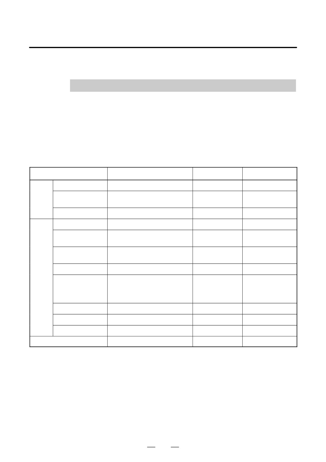
E
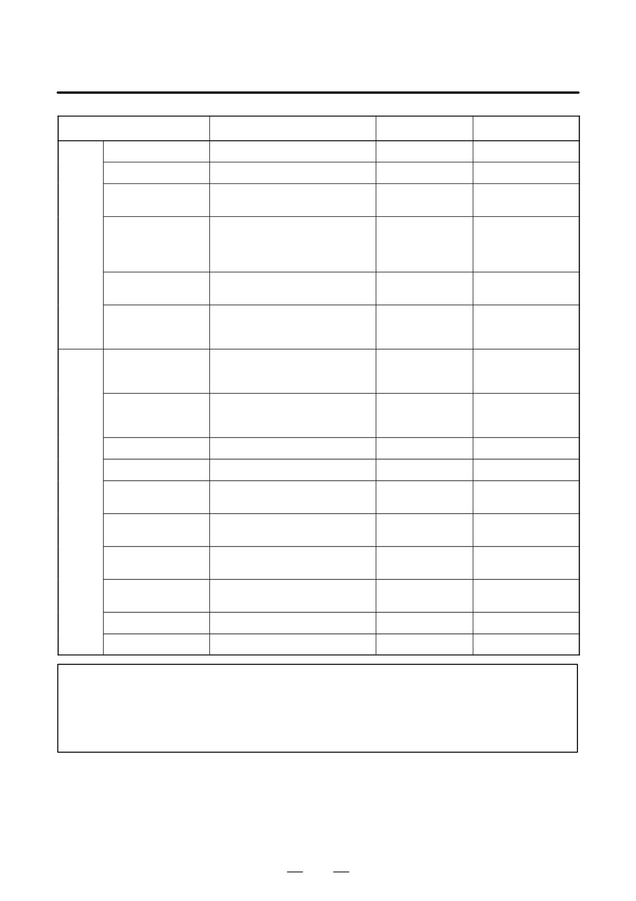
Parameter CLR (No. 3402#6) is used to select whether resetting the CNC
places it in the cleared state or in the reset state (0: reset state/1: cleared
state).
The symbols in the tables below mean the following :
f:The status is not changed or the movement is continued.
×:The status is cancelled or the movement is interrupted.
Item
When turning power on
Cleared
Reset
Setting
Offset value
f
f
f
data
Data set by the MDI
f
f
f
setting operation
Parameter
f
f
f
Various
Programs in memory
f
f
f
data
Contents in the buffer
×
×
f : MDI mode
storage
× : Other mode
Display of sequence
f
f (Note 1)
f (Note 1)
number
One shot G code
×
×
×
Modal G code
Initial G codes.
Initial G codes.
f
(The G20 and G21 codes return to
(G20/G21 are not
the same state they were in when
changed.)
the power was last turned off.)
F
Zero
Zero
f
S, T, M
×
f
f
K (Number of repeats)
×
×
×
Work coordinate value
Zero
f
f
845
E. STATUS WHEN TURNING POWER ON,
WHEN CLEAR AND WHEN RESET
APPENDIX
B-64124EN/01
Item
When turning power on
Cleared
Reset
Action in
Movement
×
×
×
opera-
Dwell
×
×
×
tion
Issuance of M, S and
×
×
×
T codes
Tool length compensa-
×
Depending on
f : MDI mode
tion
parameter
Other modes depend
LVK(No.5003#6)
on parameter
LVK(No.5003#6).
Cutter compensation
×
×
f : MDI mode
× : Other modes
Storing called subpro-
×
× (Note 2)
f : MDI mode
gram number
× : Other modes
(Note 2)
Output
CNC alarm signal
Extinguish if there is no cause for
Extinguish if there is
Extinguish if there is
signals
AL
the alarm
no cause for the
no cause for the alarm
alarm
Reference position
×
f
f
return completion LED
(× : Emergency
(× : Emergency stop)
stop)
S, T and B codes
×
f
f
M code
×
×
×
M, S and T strobe sig-
×
×
×
nals
Spindle revolution sig-
×
f
f
nal (S analog signal)
CNC ready signal
ON
f
f
MA
Servo ready signal
ON (When other than servo
ON (When other
ON (When other than
SA
alarm)
than servo alarm)
servo alarm)
Cycle start LED (STL)
×
×
×
Feed hold LED (SPL)
×
×
×
NOTE
1
When heading is performed, the main program number is displayed.
2
When a reset is performed during execution of a subprogram, control returns the head of main
program.
Execution cannot be started from the middle of the subprogram.
846
F. CHARACTER-TO-CODES
B-64124EN/01
APPENDIX
CORRESPONDENCE TABLE
CHARACTER-TO-CODES CORRESPONDENCE TABLE
F
Char-
Code
Comment
Char-
Code
Comment
acter
acter
A
065
6
054
B
066
7
055
C
067
8
056
D
068
9
057
E
069
032
Space
F
070
!
033
Exclamation mark
G
071
”
034
Quotation mark
H
072
#
035
Hash sign
I
073
$
036
Dollar sign
J
074
%
037
Percent
K
075
&
038
Ampersand
L
076
’
039
Apostrophe
M
077
(
040
Left parenthesis
N
078
)
041
Right parenthesis
O
079
042
Asterisk
P
080
+
043
Plus sign
Q
081
,
044
Comma
R
082
-
045
Minus sign
S
083
046
Period
T
084
/
047
Slash
U
085
:
058
Colon
V
086
;
059
Semicolon
W
087
<
060
Left angle bracket
X
088
=
061
Equal sign
Y
089
>
062
Right angle bracket
Z
090
?
063
Question mark
0
048
@
064
HAtI mark
1
049
[
091
Left square bracket
2
050
^
092
3
051
]
094
Right square bracket
4
052
_
095
Underscore
5
053
847
G. ALARM LIST
APPENDIX
B-64124EN/01
ALARM LIST
G
1) Program errors (P/S alarm)
Number
Message
Contents
000
PLEASE TURN OFF POWER
A parameter which requires the power off was input, turn off power.
001
TH PARITY ALARM
TH alarm (A character with incorrect parity was input). Correct the tape.
002
TV PARITY ALARM
TV alarm (The number of characters in a block is odd). This alarm will
be generated only when the TV check is effective.
003
TOO MANY DIGITS
Data exceeding the maximum allowable number of digits was input.
(Refer to the item of max. programmable dimensions.)
004
ADDRESS NOT FOUND
A numeral or the sign “ - ” was input without an address at the beginning
of a block. Modify the program .
005
NO DATA AFTER ADDRESS
The address was not followed by the appropriate data but was followed
by another address or EOB code. Modify the program.
006
ILLEGAL USE OF NEGATIVE SIGN
Sign “ .” input error (Sign “ - ” was input after an address with which it
cannot be used. Or two or more “ - ” signs were input.)
Modify the program.
007
ILLEGAL USE OF DECIMAL POINT
Decimal point “ - ” input error (A decimal point was input after an address
with which it can not be used. Or two decimal points were input.)
Modify the program.
009
ILLEGAL ADDRESS INPUT
Unusable character was input in significant area.
Modify the program.
010
IMPROPER G-CODE
An unusable G code or G code corresponding to the function not pro-
vided is specified. Modify the program.
011
NO FEEDRATE COMMANDED
Feedrate was not commanded to a cutting feed or the feedrate was in-
adequate. Modify the program.
014
CAN NOT COMMAND G95
A synchronous feed is specified without the option for threading / syn-
chronous feed.
015
TOO MANY AXES COMMANDED
The number of the commanded axes exceeded that of simultaneously
controlled axes.
020
OVER TOLERANCE OF RADIUS
In circular interpolation (G02 or G03), difference of the distance between
the start point and the center of an arc and that between the end point
and the center of the arc exceeded the value specified in parameter No.
3410.
021
ILLEGAL PLANE AXIS
An axis not included in the selected plane (by using G17, G18, G19) was
COMMANDED
commanded in circular interpolation. Modify the program.
022
NO CIRCULAR RADIUS
When circular interpolation is specified, neither R (specifying an arc ra-
dius), nor I, J, and K (specifying the distance from a start point to the cen-
ter) is specified.
025
CANNOT COMMAND F0 IN
F0 (fast feed) was instructed by F1 -digit column feed in circular inter-
G02/G03
polation. Modify the program.
027
NO AXES COMMANDED IN
No axis is specified in G43 and G44 blocks for the tool length offset type
G43/G44
C.
Offset is not canceled but another axis is offset for the tool length offset
type C. Modify the program.
028
ILLEGAL PLANE SELECT
In the plane selection command, two or more axes in the same direction
are commanded.
Modify the program.
848

B-64124EN/01
APPENDIX
G. ALARM LIST
Number
Message
Contents
029
ILLEGAL OFFSET VALUE
The offset values specified by H code is too large.
Modify the program.
030
ILLEGAL OFFSET NUMBER
The offset number specified by D/H code for tool length offset or cutter
compensation is too large. Modify the program.
031
ILLEGAL P COMMAND IN G10
In setting an offset amount by G10, the offset number following address
P was excessive or it was not specified. Alternatively, the additional
work coordinate number to be specified in a P code was too large.
Modify the program.
032
ILLEGAL OFFSET VALUE IN G10
In setting an offset amount by G10 or in writing an offset amount by sys-
tem variables, the offset amount was excessive.
033
NO SOLUTION AT CRC
A point of intersection cannot be determined for cutter compensation C.
Modify the program.
034
NO CIRC ALLOWED IN ST-UP /EXT
The start up or cancel was going to be performed in the G02 or G03
BLK
mode in cutter compensation C. Modify the program.
036
CAN NOT COMMANDED G31
Skip cutting (G31) was specified in cutter compensation mode.
Modify the program.
037
CAN NOT CHANGE PLANE IN CRC
G40 is commanded on the plane other than offset plane in cutter com-
pensation B. The plane selected by using G17, G18 or G19 is changed
in cutter compensation C mode. Modify the program.
038
INTERFERENCE IN CIRCULAR
Overcutting will occur in cutter compensation C because the arc start
BLOCK
point or end point coincides with the arc center.
Modify the program.
041
INTERFERENCE IN CRC
Overcutting will occur in cutter compensation C. Two or more blocks
are consecutively specified in which functions such as the auxiliary
function and dwell functions are performed without movement in the cut-
ter compensation mode. Modify the program.
042
G45/G48 NOT ALLOWED IN CRC
Tool offset (G45 to G48) is commanded in cutter compensation. Modify
the program.
044
G27-G30 NOT ALLOWED IN FIXED
One of G27 to G30 is commanded in canned cycle mode.
CYC
Modify the program.
045
NO G COMMAND (G73/G83)
A depth for each cutting (Q) is not commanded in canned cycle G73 or
G83. Alternatively, Q was specified. Correct the program.
046
ILLEGAL REFERENCE RETURN
Other than P2, P3 and P4 are commanded for 2nd, 3rd and 4th refer-
COMMAND
ence position return command.
050
CHF/CNR NOT ALLOWED IN THRD
Chamfering or corner R is commanded in the thread cutting block.
BLK
Modify the program.
051
MISSING MOVE AFTER CHF/CNR
Improper movement or the move distance was specified in the block
next to the chamfering or corner R block.
Modify the program.
052
CODE IS NOT G01 AFTER CHF/
The block next to the chamfering or corner R block is not G01,G02,or
CNR
G03. Modify the program.
053
TOO MANY ADDRESS COM-
For systems without the arbitary angle chamfering or corner R cutting,
MANDS
a comma was specified. For systems with this feature, a comma was fol-
lowed by something other than R or C Correct the program.
055
MISSING MOVE VALUE IN CHF/
In the arbitrary angle chamfering or corner R block, the move distance
CNR
is less than chamfer or corner R amount.
058
END POINT NOT FOUND
In a arbitrary angle chamfering or corner R cutting block, a specified axis
is not in the selected plane. Correct the program.
059
PROGRAM NUMBER NOT FOUND
In an external program number search or external workpiece number
search, a specified program number was not found. Otherwise, a pro-
gram specified for searching is being edited in background processing.
Otherwise, a program specified by an one-touch macro call is not regis-
tered in memory. Check the program number and external signal. Or dis-
continue the background editing.
849

G. ALARM LIST
APPENDIX
B-64124EN/01
Number
Message
Contents
060
SEQUENCE NUMBER NOT FOUND
Commanded sequence number was not found in the sequence number
search. Check the sequence number.
070
NO PROGRAM SPACE IN
The memory area is insufficient.
MEMORY
Delete any unnecessary programs, then retry.
071
DATA NOT FOUND
The address to be searched was not found. Or the program with speci-
fied program number was not found in program number search.
Check the data.
072
TOO MANY PROGRAMS
The number of programs to be stored exceeded 63 (basic), 125 (option),
200 (option), or
400 (option). Delete unnecessary programs and
execute program registeration again.
073
PROGRAM NUMBER ALREADY IN
The commanded program number has already been used.
USE
Change the program number or delete unnecessary programs and
execute program registeration again.
074
ILLEGAL PROGRAM NUMBER
The program number is other than 1 to 9999.
Modify the program number.
075
PROTECT
An attempt was made to register a program whose number was pro-
tected.
076
ADDRESS P NOT DEFINED
Address P (program number) was not commanded in the block which
includes an M98, G65, or G66 command. Modify the program.
077
SUB PROGRAM NESTING ERROR
The subprogram was called in five folds. Modify the program.
078
NUMBER NOT FOUND
A program number or a sequence number which was specified by ad-
dress P in the block which includes an M98, M99, M65 or G66 was not
found. The sequence number specified by a GOTO statement was not
found. Otherwise, a called program is being edited in background pro-
cessing. Correct the program, or discontinue the background editing.
079
PROGRAM VERIFY ERROR
In memory or program collation,a program in memory does not agree
with that read from an external I/O device. Check both the programs in
memory and those from the external device.
080
G37 ARRIVAL SIGNAL NOT AS-
In the automatic tool length measurement function (G37), the measure-
SERTED
ment position reach signal (XAE, YAE, or ZAE) is not turned on within
an area specified in parameter 6254 (value ε).
This is due to a setting or operator error.
081
OFFSET NUMBER NOT FOUND IN
Tool length automatic measurement (G37) was specified without a H
G37
code. (Automatic tool length measurement function) Modify the pro-
gram.
082
H-CODE NOT ALLOWED IN G37
H code and automatic tool compensation (G37) were specified in the
same block. (Automatic tool length measurement function) Modify the
program.
083
ILLEGAL AXIS COMMAND IN G37
In automatic tool length measurement, an invalid axis was specified or
the command is incremental. Modify the program.
085
COMMUNICATION ERROR
When entering data in the memory by using Reader / Puncher interface,
an overrun, parity or framing error was generated. The number of bits
of input data or setting of baud rate or specification No. of I/O unit is in-
correct.
086
DR SIGNAL OFF
When entering data in the memory by using Reader / Puncher interface,
the ready signal (DR) of reader / puncher was off.
Power supply of I/O unit is off or cable is not connected or a P.C.B. is de-
fective.
087
BUFFER OVERFLOW
When entering data in the memory by using Reader / Puncher interface,
though the read terminate command is specified, input is not interrupted
after 10 characters read. I/O unit or P.C.B. is defective.
850

B-64124EN/01
APPENDIX
G. ALARM LIST
Number
Message
Contents
090
REFERENCE RETURN INCOM-
The reference position return cannot be performed normally because
PLETE
the reference position return start point is too close to the reference posi-
tion or the speed is too slow. Separate the start point far enough from
the reference position, or specify a sufficiently fast speed for reference
position return.
091
REFERENCE RETURN
In the automatic operation halt state, manual reference position return
INCOMPLETE
cannot be performed.
092
AXES NOT ON THE REFERENCE
The commanded axis by G27 (Reference position return check) did not
POINT
return to the reference position.
094
P TYPE NOT ALLOWED
P type cannot be specified when the program is restarted. (After the au-
(COORD CHG)
tomatic operation was interrupted, the coordinate system setting opera-
tion was performed.) Perform the correct operation according to th oper-
ator’s manual.
095
P TYPE NOT ALLOWED
P type cannot be specified when the program is restarted.
(After the
(EXT OFS CHG)
automatic operation was interrupted, the external workpiece offset
amount changed.)
096
P TYPE NOT ALLOWED
P type cannot be specified when the program is restarted. (After the au-
(WRK OFS CHG)
tomatic operation was interrupted, the workpiece offset amount
changed.)
097
P TYPE NOT ALLOWED
P type cannot be directed when the program is restarted. (After power
(AUTO EXEC)
ON, after emergency stop or P/S alarm 94 to 97 were reset, no
automatic operation is performed.) Perform automatic operation.
098
G28 FOUND IN SEQUENCE
A command of the program restart was specified without the reference
RETURN
position return operation after power ON or emergency stop, and G28
was found during search. Perform the reference position return.
099
MDI EXEC NOT ALLOWED AFT.
After completion of search in program restart, a move command is given
SEARCH
with MDI.
100
PARAMETER WRITE ENABLE
On the PARAMETER(SETTING) screen, PWE(parameter writing en-
abled) is set to 1. Set it to 0, then reset the system.
101
PLEASE CLEAR MEMORY
The power turned off while rewriting the memory by program edit opera-
tion. If this alarm has occurred, press <RESET> while pressing
<PROG>, and only the program being edited will be deleted.
Register the deleted program.
109
FORMAT ERROR IN G08
A value other than 0 or 1 was specified after P in the G08 code, or no
value was specified.
110
DATA OVERFLOW
The absolute value of fixed decimal point display data exceeds the al-
lowable range. Modify the program.
111
CALCULATED DATA OVERFLOW
The result of calculation is out of the allowable range (-1047 to -10-29,
0, and 10-29 to 1047).
112
DIVIDED BY ZERO
Division by zero was specified. (including tan 90°)
113
IMPROPER COMMAND
A function which cannot be used in custom macro is commanded.
Modify the program.
114
FORMAT ERROR IN MACRO
There is an error in other formats than <Formula>.
Modify the program.
115
ILLEGAL VARIABLE NUMBER
A value not defined as a variable number is designated in the custom
macro. Modify the program.
116
WRITE PROTECTED VARIABLE
The left side of substitution statement is a variable whose substitution
is inhibited. Modify the program.
118
PARENTHESIS NESTING ERROR
The nesting of bracket exceeds the upper limit (quintuple).
Modify the program.
119
ILLEGAL ARGUMENT
The SQRT argument is negative, BCD argument is negative, or other
values than 0 to 9 are present on each line of BIN argument.
Modify the program.
851

G. ALARM LIST
APPENDIX
B-64124EN/01
Number
Message
Contents
122
QUADRUPLICATE MACRO
A total of four macro calls and macro modal calls are nested. Correct
MODAL-CALL
the program.
123
CAN NOT USE MACRO COMMAND
Macro control command is used during DNC operation.
IN DNC
Modify the program.
124
MISSING END STATEMENT
DO - END does not correspond to 1 : 1. Modify the program.
125
FORMAT ERROR IN MACRO
<Formula> format is erroneous. Modify the program.
126
ILLEGAL LOOP NUMBER
In DOn, 1x n x3 is not established. Modify the program.
127
NC, MACRO STATEMENT IN SAME
NC and custom macro commands coexist.
BLOCK
Modify the program.
128
ILLEGAL MACRO SEQUENCE NUM-
The sequence number specified in the branch command was not 0 to
BER
9999. Or, it cannot be searched. Modify the program.
129
ILLEGAL ARGUMENT ADDRESS
An address which is not allowed in <Argument Designation > is used.
Modify the program.
130
ILLEGAL AXIS OPERATION
An axis control command was given by PMC to an axis controlled by
CNC. Or an axis control command was given by CNC to an axis con-
trolled by PMC. Modify the program.
131
TOO MANY EXTERNAL ALARM
Five or more alarms have generated in external alarm message.
MESSAGES
Consult the PMC ladder diagram to find the cause.
132
ALARM NUMBER NOT FOUND
No alarm No. concerned exists in external alarm message clear.
Check the PMC ladder diagram.
133
ILLEGAL DATA IN EXT. ALARM
Small section data is erroneous in external alarm message or exter-
MSG
nal operator message. Check the PMC ladder diagram.
135
ILLEGAL ANGLE COMMAND
The index table indexing positioning angle was instructed in other
than an integral multiple of the value of the minimum angle.
Modify the program.
136
ILLEGAL AXIS COMMAND
In index table indexing, another control axis was instructed together
with the B axis.
Modify the program.
139
CAN NOT CHANGE PMC
An axis is selected in commanding by PMC axis control.
CONTROL AXIS
Modify the program.
141
CAN NOT COMMAND G51 IN CRC
G51 (Scaling ON) is commanded in the tool offset mode.
Modify the program.
142
ILLEGAL SCALE RATE
Scaling magnification is commanded in other than 1 - 999999.
Correct the scaling magnification setting (G51 Pp . . or parameter
5411 or 5421).
143
SCALED MOTION DATA OVER-
The scaling results, move distance, coordinate value and circular
FLOW
radius exceed the maximum command value. Correct the program or
scaling mangification.
144
ILLEGAL PLANE SELECTED
The coordinate rotation plane and arc or cutter compensation C
plane must be the same. Modify the program.
148
ILLEGAL SETTING DATA
Automatic corner override deceleration rate is out of the settable
range of judgement angle. Modify the parameters (No.1710 to
No.1714)
149
FORMAT ERROR IN G10L3
A code other than Q1,Q2,P1 or P2 was specified as the life count
type in the extended tool life management.
150
ILLEGAL TOOL GROUP NUMBER
Tool Group No. exceeds the maximum allowable value.
Modify the program.
151
TOOL GROUP NUMBER NOT
The tool group commanded in the machining program is not set.
FOUND
Modify the value of program or parameter.
152
NO SPACE FOR TOOL ENTRY
The number of tools within one group exceeds the maximum value
registerable. Modify the number of tools.
852

B-64124EN/01
APPENDIX
G. ALARM LIST
Number
Message
Contents
153
T-CODE NOT FOUND
In the registration of tool life data, a T code was not specified in a
block where it is required. Alternatively, only M06 was specified in a
block for tool change type D. Correct the program.
154
NOT USING TOOL IN LIFE GROUP
When the group is not commanded, H99 or D99 was commanded.
Correct the program.
155
ILLEGAL T-CODE IN M06
In the machining program, M06 and T code in the same block do not
correspond to the group in use. Correct the program.
156
P/L COMMAND NOT FOUND
P and L commands are missing at the head of program in which the
tool group is set. Correct the program.
157
TOO MANY TOOL GROUPS
The number of tool groups to be set exceeds the maximum allowable
value. See parameter GS1, GS2 (No. 6800 bit 0 and 1). Modify the
program.
158
ILLEGAL TOOL LIFE DATA
The tool life to be set is too excessive. Modify the setting value.
159
TOOL DATA SETTING INCOM-
During executing a life data setting program, power was turned off.
PLETE
Set again.
175
ILLEGAL G107 COMMAND
Conditions when performing cylindrical interpolation start or cancel
not correct. To change the mode to the cylindrical interpolation
mode, specify the command in a format of “G07.1 rotation-axis name
radius of cylinder.”
176
IMPROPER G-CODE IN G107
Any of the following G codes which cannot be specified in the cylin-
drical interpolation mode was specified.
1) G codes for positioning, such as G28,, G73, G74, G76, G81 - G89,
including the codes specifying the rapid traverse cycle
2) G codes for setting a coordinate system: G52,G92,
3) G code for selecting coordinate system: G53 G54-G59
Modify the program.
177
CHECK SUM ERROR
Check sum error
(G05 MODE)
Modify the program.
178
G05 COMMANDED IN G41/G42
G05 was commanded in the G41/G42 mode.
MODE
Correct the program.
179
PARAM. (PRM NO. 7510) SETTING
The number of controlled axes set by the parameter 7510 exceeds
ERROR
the maximum number. Modify the parameter setting value.
180
COMMUNICATION ERROR
Remote buffer connection alarm has generated. Confirm the number of
(REMOTE BUF)
cables, parameters and I/O device.
190
ILLEGAL AXIS SELECT
In the constant surface speed control, the axis specification is wrong.
(See parameter No. 3770.) The specified axis command (P) contains
an illegal value.
Correct the program.
194
SPINDLE COMMAND IN
A contour control mode, spindle positioning (Cs-axis control) mode,
SYNCHRO-MODE
or rigid tapping mode was specified during the serial spindle
synchronous control mode. Correct the program so that the serial
spindle synchronous control mode is released in advance.
197
C-AXIS COMMANDED IN SPINDLE
The program specified a movement along the Cs-axis when the sig-
MODE
nal CON(DGN=G027#7) was off. Correct the program, or consult the
PMC ladder diagram to find the reason the signal is not turned on.
199
MACRO WORD UNDEFINED
Undefined macro word was used. Modify the custom macro.
200
ILLEGAL S CODE COMMAND
In the rigid tap, an S value is out of the range or is not specified.
The maximum value for S which can be specified in rigid tapping is
set in parameter (No.5241 to 5243). Change the setting in the
parameter or modify the program.
201
FEEDRATE NOT FOUND IN RIGID
In the rigid tapping, no F value is specified.
TAP
Correct the program.
202
POSITION LSI OVERFLOW
In the rigid tapping, spindle distribution value is too large.
853

G. ALARM LIST
APPENDIX
B-64124EN/01
Number
Message
Contents
203
PROGRAM MISS AT RIGID
In the rigid tapping, position for a rigid M code (M29) or an S
TAPPING
command is incorrect. Modify the program.
204
ILLEGAL AXIS OPERATION
In the rigid tapping, an axis movement is specified between the rigid
M code (M29) block and G84 (G74) block. Modify the program.
205
RIGID MODE DI SIGNAL OFF
Rigid tapping signal (DGNG061 #1) is not 1 when G84 (G88) is
executed though the rigid M code (M29) is specified.
Consult the PMC ladder diagram to find the reason the signal is not
turned on.
206
CAN NOT CHANGE PLANE
Plane changeover was instructed in the rigid mode.
(RIGID TAP)
Correct the program.
207
RIGID DATA MISMATCH
The specified distance was too short or too long in rigid tapping.
210
CAN NOT COMAND M198/M99
1) M198 and M99 are executed in the schedule operation. Or M198
is executed in the DNC operation.
2) In a multiple repetitive pocketing canned cycle, an interrupt macro
was specified, and M99 was executed.
212
ILLEGAL PLANE SELECT
The arbitrary angle chamfering or a corner R is commanded or the
plane including an additional axis. Correct the program.
213
ILLEGAL COMMAND IN
Any of the following alarms occurred in the operation with the simple
SYNCHRO-MODE
synchronization control.
1) The program issued the move command to the slave axis.
2) The program issued the manual continuous feed/manual handle
feed/incremental feed command to the slave axis.
3) The program issued the automatic reference position return com-
mand without executing the manual reference position return after
the power was turned on.
4) The difference between the position error amount of the master and
slave axes exceeded the value specified in parameter No. 8313.
214
ILLEGAL COMMAND IN
Coordinate system is set or tool compensation of the shift type is
SYNCHRO-MODE
executed in the synchronous control. Correct the program.
224
RETURN TO REFERENCE POINT
Reference position return has not been performed before the auto-
matic operation starts. Perform reference position return only when
parameter ZRNX (No.1005#0) is 0.
231
ILLEGAL FORMAT IN G10 OR L50
Any of the following errors occurred in the specified format at the
programmable-parameter input.
1) Address N or R was not entered.
2) A number not specified for a parameter was entered.
3) The axis number was too large.
4) An axis number was not specified in the axis-type parameter.
5) An axis number was specified in the parameter which is not an axis
type.
6) An attempt was made to reset bit 4 of parameter 3202 (NE9) or
change parameter 3210 (PSSWD) when they are protected by a
password. Correct the program.
232
TOO MANY HELICAL AXIS
Three or more axes (in the normal direction control mode two or more
COMMANDS
axes) were specified as helical axes in the helical interpolation mode.
233
DEVICE BUSY
When an attempt was made to use a unit such as that connected via
the RS-232-C interface, other users were using it.
239
BP/S ALARM
While punching was being performed with the function for controlling
external I/O units ,background editing was performed.
240
BP/S ALARM
Background editing was performed during MDI operation.
253
G05 IS NOT AVAIRABLE
Binary-input operation with a high-speed remote buffer (G05) or
high-speed cycle machining (G05) has been specified in look-ahead
control mode (G08P1). Before attempting to specify these
commands, first specify G08P0; to cancel look-ahead control mode.
854

B-64124EN/01
APPENDIX
G. ALARM LIST
Number
Message
Contents
5010
END OF RECORD
The end of record (%) was specified.
5020
PARAMETER OF RESTART
The parameter for specifying program restart is not set correctly.
ERROR
5046
ILLEGAL PARAMETER (ST.COMP)
An illegal parameter has been specified for straightness compensa-
tion.
Possible reasons are as follows:
1
There is no axis corresponding to the axis number specified in the
move axis or compensation axis parameter.
2
More than 128 pitch error compensation points are not sequentially
numbered.
3
The straightness compensation points are not sequentially num-
bered.
4
A specified straightness compensation point is outside the range
between the pitch error compensation points having the maximum
positive and negative coordinates.
5
The compensation value specified for each compensation point is
too large or too small.
5073
NO DECIMAL POINT
A decimal point is not specified for a command for which a decimal
point must be specified.
5074
ADDRESS DUPLICATION ERROR
The same address appears more than once in a block. Alternatively,
a block contains two or more G codes belonging to the same group.
5110
IMPROPER G-CODE
An illegal G code was specified in AI look-ahead control mode.
(G05.1 Q1 MODE)
5111
IMPROPER MODAL G-CODE
An illegal G code is left modal when AI look-ahead control mode was
(G05.1 Q1)
specified.
5112
G08 CAN NOT BE COMMANDED
Look-ahead control (G08) was specified in AI look-ahead control
(G05.1 Q1)
mode.
5114
NOT STOP POSITION
At the time of restart after manual intervention, the coordinates at which
(G05.1 Q1)
the manual intervention occurred have not been restored.
5134
FSSB : OPEN READY TIME OUT
The FSSB did not become ready to open during initialization.
5135
FSSB : ERROR MODE
The FSSB entered an error mode.
5136
FSSB : NUMBER OF AMPS IS
The number of amplifiers recognized by the FSSB is insufficient,
SMALL
compared with the number of controlled axes.
5137
FSSB : CONFIGURATION ERROR
The FSSB detected a configuration error.
5138
FSSB : AXIS SETTING NOT
Axis setting has not been performed in automatic setting mode. Per-
COMPLETE
form axis setting using the FSSB setting screen.
5139
FSSB : ERROR
Servo initialization did not terminate normally.
The optical cable may be defective, or there may be an error in connec-
tion to the amplifier or another module.
Check the optical cable and the connection status.
5156
ILLEGAL AXIS OPERATION (AICC)
In AI look-ahead control mode, the controlled axis selection signal
(PMC axis control) changes.
In AI look-ahead control mode, the simple synchronous axis selection
signal changes.
5157
PARAMETER ZERO (AICC)
Zero is set in the parameter for the maximum cutting feedrate (parame-
ter No. 1422 or 1432).
Zero is set in the parameter for the acceleration/deceleration before in-
terpolation (parameter No. 1770 or 1771).
5197
FSSB : OPEN TIME OUT
The FSSB did not open when the CNC had allowed the FSSB to
open.
5198
FSSB : ID DATA NOT READ
The initial ID information for the amplifier cannot be read because of
a failure in the temporary assignment.
855

G. ALARM LIST
APPENDIX
B-64124EN/01
Number
Message
Contents
5212
SCREEN COPY : PARAMETER
There is a parameter setting error. Check that 4 is set as the I/O channel.
ERROR
5213
SCREEN COPY : COMMUNICA-
The memory card cannot be used. Check the memory card. (Check
TION ERROR
whether the memory card is write-protected or defective.)
5214
SCREEN COPY : DATA TRANSFER
Data transfer to the memory card failed.
ERROR
Check whether the memory card space is insufficient and whether the
memory card was removed during data transfer.
5220
REFERENCE POINT
A parameter for automatically set a reference position is set. (Bit 2 of
ADJUSTMENT MODE
parameter No. 1819 = 1)
Perform automatic setting.
(Position the machine at the reference position manually, then perform
manual reference position return.)
Supplementary: Automatic setting sets bit 2 of parameter No. 1819 to 0.
5222
SRAM CORRECTABLE ERROR
The SRAM correctable error cannot be corrected.
Cause:
A memory problem occurred during memory initialization.
Action:
Replace the master printed circuit board (SRAM module).
5227
FILE NOT FOUND
A specified file is not found during communication with the built-in
Handy File.
5228
SAME NAME USED
There are duplicate file names in the built-in Handy File.
5229
WRITE PROTECTED
A floppy disk in the built-in Handy File is write protected.
5231
TOO MANY FILES
The number of files exceeds the limit during communication with the
built-in Handy File.
5232
DATA OVER-FLOW
There is not enough floppy disk space in the built-in Handy File.
5235
COMMUNICATION ERROR
A communication error occurred during communication with the built-in
Handy File.
5237
READ ERROR
A floppy disk in the built-in Handy File cannot be read from. The floppy
disk may be defective, or the head may be dirty. Alternatively, the Handy
File is defective.
5238
WRITE ERROR
A floppy disk in the built-in Handy File cannot be written to. The floppy
disk may be defective, or the head may be dirty. Alternatively, the Handy
File is defective.
5257
G41/G42 NOT ALLOWED IN MDI
G41/G42 (cutter compensation C: M series, tool-nose radius com-
MODE
pensation: T series) was specified in MDI mode. (Depending on the set-
ting of bit 4 of parameter No. 5008)
5303
TOUCH PANEL ERROR
A touch panel error occurred.
Cause:
1. The touch panel is kept pressed.
2. The touch panel was pressed when power was turned on.
Remove the above causes, and turn on the power again.
5306
MODE CHANGE ERROR
In an one-touch macro call, the mode is not normally switched at the
beginning.
5311
FSSB : ILLEGAL CONNECTION
1. This alarm is issued if, in a pair of axes in which one axis has an
odd servo axis number (parameter No. 1023) and the other has an
even servo axis number that is adjacent to the odd servo axis
number, one of the axes is assigned to an amplifier connected to
an FSSB in a system different from that for the other axis.
2. This alarm is issued if the system does not satisfy a constraint for
performing high-speed HRV control, current control periods for
two FSSBs are different, and it is specified that pulse modules
connected to an FSSB in different paths are to be used.
856
B-64124EN/01
APPENDIX
G. ALARM LIST
2) Background edit alarm
Number
Message
Contents
???
BP/S alarm
BP/S alarm occurs in the same number as the P/S alarm that occurs in
ordinary program edit.
(P/S alarm No. 070, 071, 072, 073, 074, 085 to 087)
Modify the program.
140
BP/S alarm
It was attempted to select or delete in the background a program being
selected in the foreground. (Note)
Use background editing correctly.
NOTE
Alarm in background edit is displayed in the key input line of the background edit screen instead
of the ordinary alarm screen and is resettable by any of the MDI key operation.
3) Absolute pulse coder (APC) alarm
Number
Message
Contents
300
nth-axis origin return
Manual reference position return is required for the nth-axis (n=1 - 4).
301
APC alarm: nth-axis communication
nth-axis (n=1 - 4) APC communication error. Failure in data transmission
Possible causes include a faulty APC, cable, or servo interface module.
302
APC alarm: nth-axis over time
nth-axis (n=1 - 4) APC overtime error.
Failure in data transmission.
Possible causes include a faulty APC, cable, or servo interface module.
303
APC alarm: nth-axis framing
nth-axis (n=1 - 4) APC framing error. Failure in data transmission.
Possible causes include a faulty APC, cable, or servo interface module.
304
APC alarm: nth-axis parity
nth-axis (n=1 - 4) APC parity error.
Failure in data transmission.
Possible causes include a faulty APC, cable, or servo interface module.
305
APC alarm: nth-axis pulse error
nth-axis (n=1 - 4) APC pulse error alarm.
APC alarm.APC or cable may be faulty.
306
APC alarm: nth-axis battery voltage 0
nth-axis (n=1 - 4) APC battery voltage has decreased to a low level so
that the data cannot be held.
APC alarm. Battery or cable may be faulty.
307
APC alarm: nth-axis battery low 1
nth-axis (n=1 - 4) axis APC battery voltage reaches a level where the
battery must be renewed.
APC alarm. Replace the battery.
308
APC alarm: nth-axis battery low 2
nth-axis (n=1 - 4) APC battery voltage has reached a level where the
battery must be renewed (including when power is OFF).
APC alarm .Replace battery.
309
APC ALARM : n AXIS ZRN
An attempt was made to perform reference position return without rotat-
IMPOSSIBL
ing the motor through one or more turns. Rotate the motor through one
or more turns, turn off the power then on again, then perform reference
position return.
857

G. ALARM LIST
APPENDIX
B-64124EN/01
4) Serial pulse coder (SPC) alarms
No.
Message
Description
360
n AXIS : ABNORMAL CHECKSUM
A checksum error occurred in the built-in pulse coder.
(INT)
361
n AXIS : ABNORMAL PHASE DATA
A phase data error occurred in the built-in pulse coder.
(INT)
362
n AXIS : ABNORMAL REV.DATA
A rotation speed count error occurred in the built-in pulse coder.
(INT)
363
n AXIS : ABNORMAL CLOCK (INT)
A clock error occurred in the built-in pulse coder.
364
n AXIS : SOFT PHASE ALARM (INT)
The digital servo software detected invalid data in the built-in pulse
coder.
365
n AXIS : BROKEN LED (INT)
An LED error occurred in the built-in pulse coder.
366
n AXIS : PULSE MISS (INT)
A pulse error occurred in the built-in pulse coder.
367
n AXIS : COUNT MISS (INT)
A count error occurred in the built-in pulse coder.
368
n AXIS : SERIAL DATA ERROR
Communication data from the built-in pulse coder cannot be re-
(INT)
ceived.
369
n AXIS : DATA TRANS. ERROR
A CRC or stop bit error occurred in the communication data being
(INT)
received from the built-in pulse coder.
380
n AXIS : BROKEN LED (EXT)
The separate detector is erroneous.
381
n AXIS : ABNORMAL PHASE
A phase data error occurred in the separate linear scale.
(EXT LIN)
382
n AXIS : COUNT MISS (EXT)
A pulse error occurred in the separate detector.
383
n AXIS : PULSE MISS (EXT)
A count error occurred in the separate detector.
384
n AXIS : SOFT PHASE ALARM
The digital servo software detected invalid data in the separate de-
(EXT)
tector.
385
n AXIS : SERIAL DATA ERROR
Communication data from the separate detector cannot be received.
(EXT)
386
n AXIS : DATA TRANS. ERROR
A CRC or stop bit error occurred in the communication data being
(EXT)
received from the separate detector.
387
n AXIS : ABNORMAL ENCODER
An error occurs in the separate detector. For details, contact the
(EXT)
manufacturer of the scale.
858