FANUC Series 0i-MC. OPERATOR’S MANUAL - page 17
B-64124EN/01
OPERATION
3. MANUAL OPERATION
MANUAL OPERATION
3
MANUAL OPERATION are six kinds as follows :
3.1
MANUAL REFERENCE POSITION RETURN
3.2
JOG FEED
3.3
INCREMENTAL FEED
3.4
MANUAL HANDLE FEED
3.5
MANUAL ABSOLUTE ON AND OFF
463
3. MANUAL OPERATION
OPERATION
B-64124EN/01
The tool is returned to the reference position as follows :
3.1
The tool is moved in the direction specified in parameter ZMI (bit 5 of No.
MANUAL
1006) for each axis with the reference position return switch on the
REFERENCE
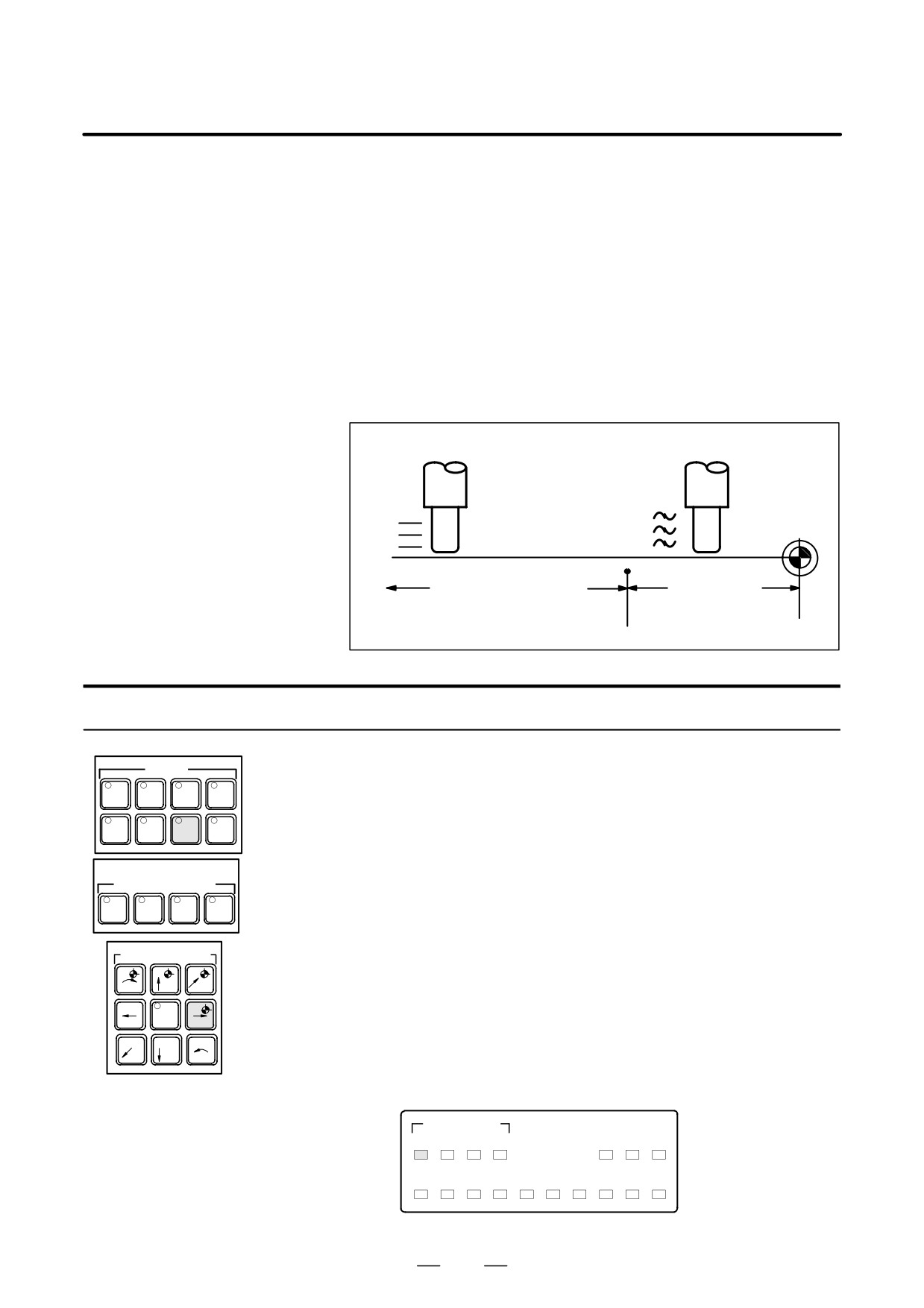
machine operator’s panel. The tool moves to the deceleration point at the
rapid traverse rate, then moves to the reference position at the FL speed.
POSITION RETURN
The rapid traverse rate and FL speed are specified in parameters (No.
1420,1421, and 1425).
Fourstep rapid traverse override is effective during rapid traverse.
When the tool has returned to the reference position, the reference
position return completion LED goes on. The tool generally moves along
only a single axis, but can move along three axes simultane ously when
specified so in parameter JAX(bit 0 of No.1002).
Reference
position
ÇÇ
ÇÇ
Deceleration
ÇÇ
point
ÇÇ
ÇÇ
ÇÇ
Rapid traverse motion
Decelerated
motion
Rapid traverse rate
FL speed
(rapid traverse override is
effective)
Procedure for Manual Reference Position Return
Procedure
1
Press the reference position return switch, one of the mode selection
MODE
swithces.
EDIT
MEMORY
REMOTE
MDI
2
To decerease the feedrate, press a rapid traverse override switch.
HANDLE
JOG
ZERO
TEACH
RETURN
When the tool has returned to the reference position, the reference
position return completion LED goes on.
RAPID TRAVERSE
OVERRIDE (%)
3
Press the feed axis and direction selection switch corresponding to the
F0
25
50
100
axis and direction for reference position return. Continue pressing the
switch until the tool returns to the reference position. The tool can be
AXIS DIRECTION
moved along three axes simultaneously when specified so in an
appropriate parameter setting. The tool moves to the deceleration
+C
+Z
+Y
point at the rapid traverse rate, then moves to the reference position at
the FL speed set in a parameter.
-X
RAPID
+X
4
Perform the same operations for other axes, if necessary.
–Y
-Z
-C
The above is an example. Refer to the appropriate manual provided by
the machine tool builder for the actual operations.
ZERO POSITION
MIRRROR IMAGE
X Y Z C
X Y Z
PROGRAM
M02/
MANU
SPINDLE
ATC
STOP
M30
ABS
ORI
TAP
READY
NC? MC?
464
B-64124EN/01
OPERATION
3. MANUAL OPERATION
Explanations
D Automatically setting the
The coordinate system is automatically determined when manual
coordinate system
reference position return is performed.
When a, b and g are set in workpiece zero point offset values, the
workpiece coordinate system is determined so that reference point on the
tool holder or the position of the tip of the reference tool is X= a, Y = b,
Z = g when reference position return is performed. This has the same
effect as specifying the following command for reference position return:
G92XaYbZg;
Restrictions
D Moving the tool again
Once the REFERENCE POSITION RETURN COMPLETION LED
lights at the completion of reference position return, the tool does not
move unless the REFERENCE POSITION RETURN switch is turned
off.
D Reference position return
The REFERENCE POSITION RETURN COMPLETION LED is
completion LED
extinguished by either of the following operations:
- Moving from the reference position.
- Entering an emergency stop state.
D The distance to return to
For the distance (Not in the deceleration condition) to return the tool to
reference position
the reference position, refer to the manual issued by the machine tool
builder.
465
3. MANUAL OPERATION
OPERATION
B-64124EN/01
3.2
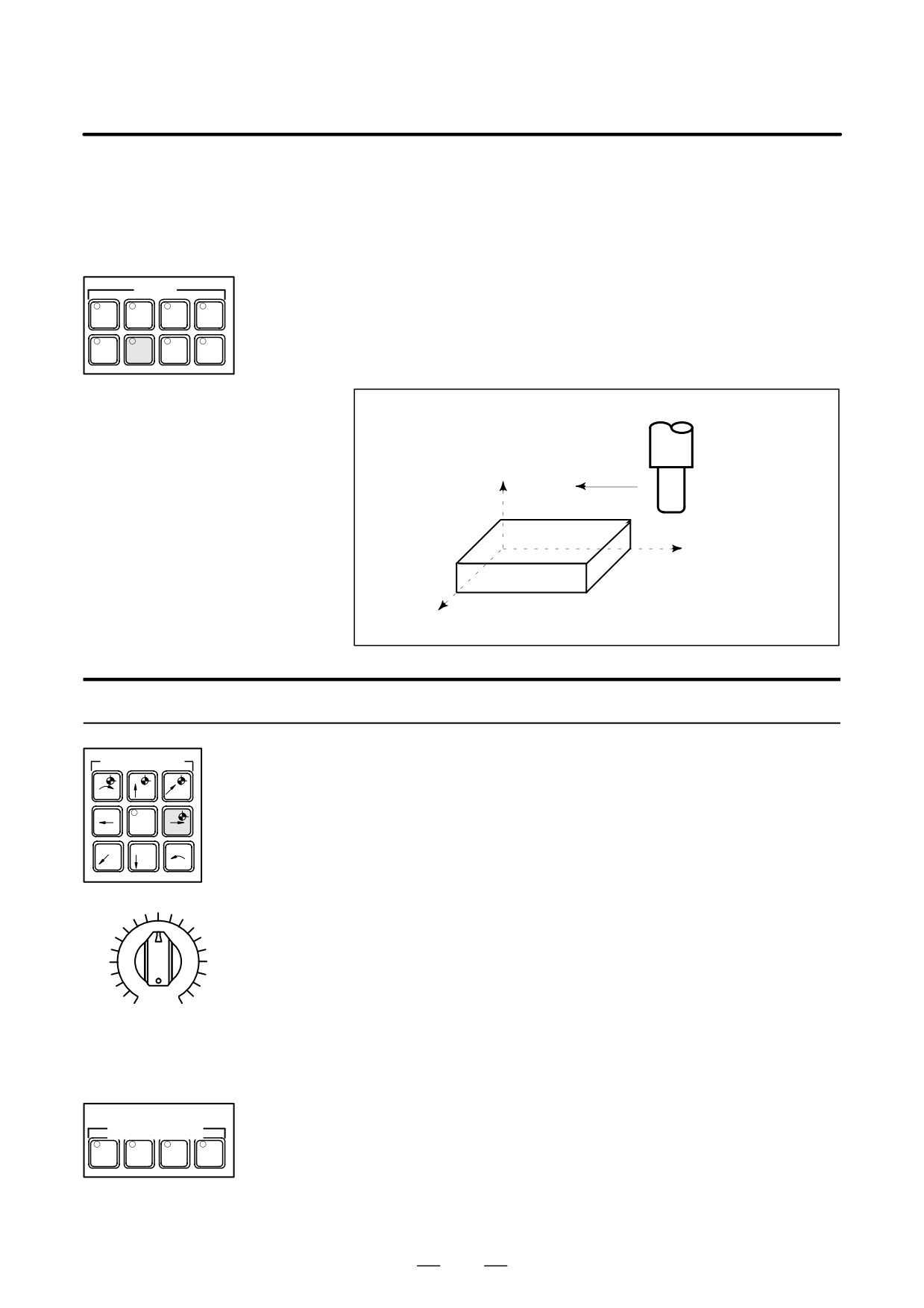
In the jog mode, pressing a feed axis and direction selection switch on the
JOG FEED
machine operator’s panel continuously moves the tool along the selected
axis in the selected direction.
The jog feedrate is specified in a parameter (No.1423)
The jog feedrate can be adjusted with the jog feedrate override dial.
MODE
Pressing the rapid traverse switch moves the tool at the rapid traverse
EDIT
MEMORY
REMOTE
MDI
feedrate (No. 1424) regardless of the postiotion of the jog feedrate
override dial. This function is called the manual rapid traverse.
HANDLE
TEACH
JOGÂÂ
RETURN
Manual operation is allowed for one axis at a time. 3 axes can be
ÂÂ
selected at a time by parameter JAX (No.1002#0).
Z
ÇÇ
ÇÇ
ÇÇ
Y
While a switch is pressed, the
tool moves in the direction
X
specified by the switch.
Procedure for JOG feed
AXIS DIRECTION
Procedure
1
Press the jog switch, one of the mode selection switches.
+C
+Z
+Y
2
Press the feed axis and direction selection switch corresponding to the
axis and direction the tool is to be moved. While the switch is pressed,
–X
RAPID
+X
the tool moves at the feedrate specified in a parameter (No. 1423).
The tool stops when the switch is released.
-Y
-Z
-C
3
The jog feedrate can be adjusted with the jog feedrate override dial.
4
Pressing the rapid traverse switch while pressing a feed axis and
direction selection switch moves the tool at the rapid traverse rate
while the rapid traverse switch is pressed. Rapid traverse override by
the rapid traverse override switches is effective during rapid traverse.
0
2000
The above is an example. Refer to the appropriate manual provided
by the machine tool builder for the actual operations.
JOG FEED RATE OVERRIDE
RAPID TRAVERSE
OVERRIDE (%)
F0
25
50
100
466
B-64124EN/01
OPERATION
3. MANUAL OPERATION
Limitations
D Acceleration/decelera-
Feedrate, time constant and method of automatic acceleration/
tion for rapid traverse
deceleration for manual rapid traverse are the same as G00 in programmed
command.
D Change of modes
Changing the mode to the jog mode while pressing a feed axis and
direction selection switch does not enable jog feed. To enable jog feed,
enter the jog mode first, then press a feed axis and direction selection
switch.
D Rapid traverse prior to
If reference position return is not performed after power-on, pushing
reference position return
RAPID TRAVERSE button does not actuate the rapid traverse but the
remains at the JOG feedrate. This function can be disabled by setting
parameter RPD (No.1401#01).
467
3. MANUAL OPERATION
OPERATION
B-64124EN/01
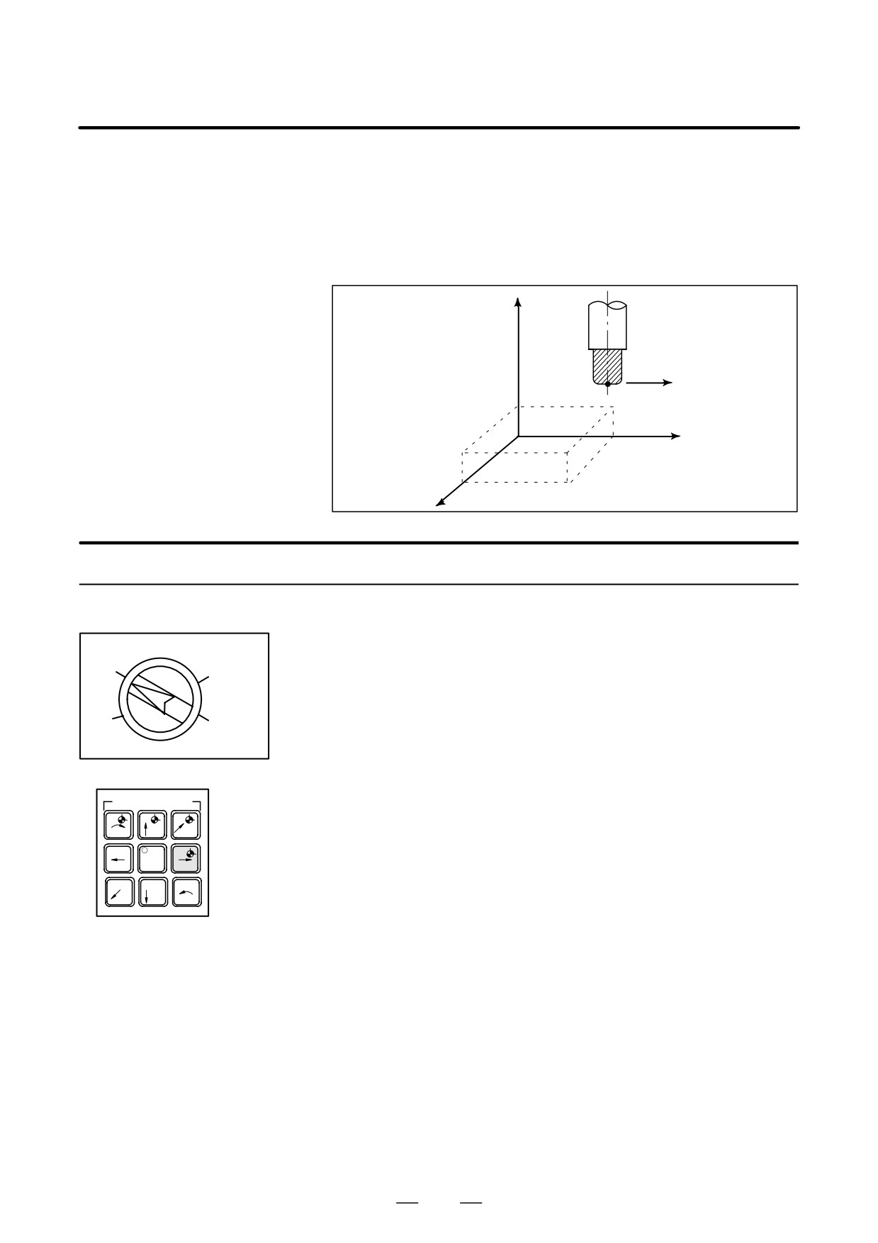
In the incremental (INC) mode, pressing a feed axis and direction
3.3
selection switch on the machine operator’s panel moves the tool one step
INCREMENTAL FEED
along the selected axis in the selected direction. The minimum distance
the tool is moved is the least input increment. Each step can be 10, 100,
or 1000 times the least input increment.
This mode is effective when a manual pulse generator is not connected.
Z
Each time a switch is
Tool
pressed, the tool moves
one step in the direction
specified by the switch.
Y
X
Procedure for Incremental Feed
1
Press the INC switch, one of the mode selection switches.
2
Select the distance to be moved for each step with the
X10
X100
magnification dial.
3
Press the feed axis and direction selection switch corresponding to
the axis and direction the tool is to be moved. Each time a switch
X1
X1000
is pressed, the tool moves one step. The feedrate is the same as the
jog feedrate.
4
Pressing the rapid traverse switch while pressing a feed axis and
AXIS DIRECTION
direction selection switch moves the tool at the rapid traverse rate.
Rapid traverse override by the rapid traverse override switch is
+C
+Z
+Y
effective during rapid traverse.
–X
RAPID
+X
The above is an example. Refer to the appropriate manual provided
-Y
-Z
-C
by the machine tool builder for the actual operations.
468
B-64124EN/01
OPERATION
3. MANUAL OPERATION
3.4
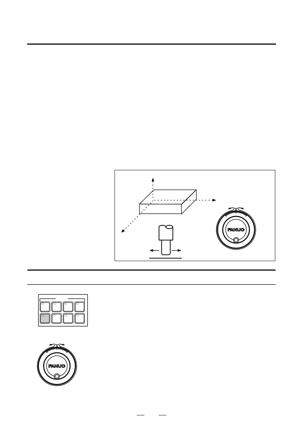
In the handle mode, the tool can be minutely moved by rotating the
manual pulse generator on the machine operator’s panel. Select the axis
MANUAL HANDLE
along which the tool is to be moved with the handle feed axis selection
FEED
switches.
The minimum distance the tool is moved when the manual pulse
generator is rotated by one graduation is equal to the least input increment.
Or the distance the tool is moved when the manual pulse generator is
rotated by one graduation can be magnified by 1 times, 10 times, or by
one of the two magnifications (total four magnifications) specified by
parameters (No. 7113 and 7114).
In addition to using parameters No. 7113 and No. 7114 to set arbitrary
magnifications common to all axes, the user can use parameters No.
12350 and No. 12351 to set arbitrary magnifications independently for
individual axes.
When parameter No. 12350 has no value, parameter No. 7113 is used;
when parameter No. 12351 has no value, parameter No. 7114 is used.
These parameters are also valid for manual handle interruption.
Z
Y
X
ÇÇ
ÇÇ
ÇÇ
Manual pulse generator
Procedure for Manual Handle Feed
1
Press the HANDLE switch, one of the mode selection switches.
MODE
2
Select the axis along which the tool is to be moved by pressing a
EDIT
MEMORY
REMOTE
MDI
handle feed axis selection switch.
HANDLE
JOG
ZERO
TEACH
RETURN
3
Select the magnification for the distance the tool is to be moved by
pressing a handle feed magnification switch. The distance the tool is
moved when the manual pulse generator is rotated by one graduation
is: Least input increment multiplied by magnification.
4
Move the tool along the selected axis by rotating the handle. Rotating
the handle 360 degrees moves the tool the distance equivalent to 100
graduations.
The above is an example. Refer to the appropriate manual provided
by the machine tool builder for the actual operations.
Manual pulse generator
469
3. MANUAL OPERATION
OPERATION
B-64124EN/01
Explanations
D Availability of manual
Parameter JHD (bit 0 of No. 7100) enables or disables the manual handle
pulse generator in Jog
feed in the JOG mode.
mode (JHD)
When the parameter JHD( bit 0 of No. 7100) is set 1,both manual handle
feed and incremental feed are enabled.
D Availability of manual
Parameter THD (bit 1 of No. 7100) enables or disables the manual handle
pulse generator in
feed in the TEACH IN JOG mode.
TEACH IN JOG mode
(THD)
D A command to the MPG
Parameter HPF (bit 4 of No. 7100) or (No. 7117) specifies as follows:
exceeding rapid traverse
D Parameter HPF (bit 4 of No. 7100)
rate (HPF)
Set value 0 : The feedrate is clamped at the rapid traverse rate and
generated pulses exceeding the rapid traverse rate are
ignored. (The distance the tool is moved may not match
the graduations on the manual pulse generator.)
Set value 1 : The feedrate is clamped at the rapid traverse rate and
generated pulses exceeding the rapid traverse rate are not
ignored but accumulated in the CNC.
(No longer rotating the handle does not immediately
stop the tool. The tool is moved by the pulses
accumulated in the CNC before it stops.)
D Parameter HPF (No. 7177) (It is available when parameter HPF is 0.)
Set value 0 : The feedrate is clamped at the rapid traverse rate and
generated pulses exceeding the rapid traverse rate are
ignored. (The distance the tool is moved may not match
the graduations on the manual pulse generator.)
Other than 0 : The feedrate is clamped at the rapid traverse rate and
generated pulses exceeding the rapid traverse rate are not
ignored but accumulated in the CNC until the limit
specified in parameter No. 7117 is reached.
(No longer rotating the handle does not immediately
stop the tool. The tool is moved by the pulses
accumulated in the CNC before it stops.)
D Movement direction of
Parameter HNGx (No. 7102 #0) switches the direction of MPG in which
an axis to the rotation of
the tool moves along an axis, corresponding to the direction in which the
MPG (HNGX)
handle of the manual pulse generator is rotated.
470

B-64124EN/01
OPERATION
3. MANUAL OPERATION
Restrictions
D Number of MPGs
Up to three manual pulse generators can be connected, one for each axis.
The three manual pulse generators can be simultaneously operated.
WARNING
Rotating the handle quickly with a large magnification such
as x100 moves the tool too fast. The feedrate is clamped
at the rapid traverse feedrate.
NOTE
Rotate the manual pulse generator at a rate of five rotations
per second or lower. If the manual pulse generator is
rotated at a rate higher than five rotations per second, the
tool may not stop immediately after the handle is no longer
rotated or the distance the tool moves may not match the
graduations on the manual pulse generator.
471
3. MANUAL OPERATION
OPERATION
B-64124EN/01
3.5
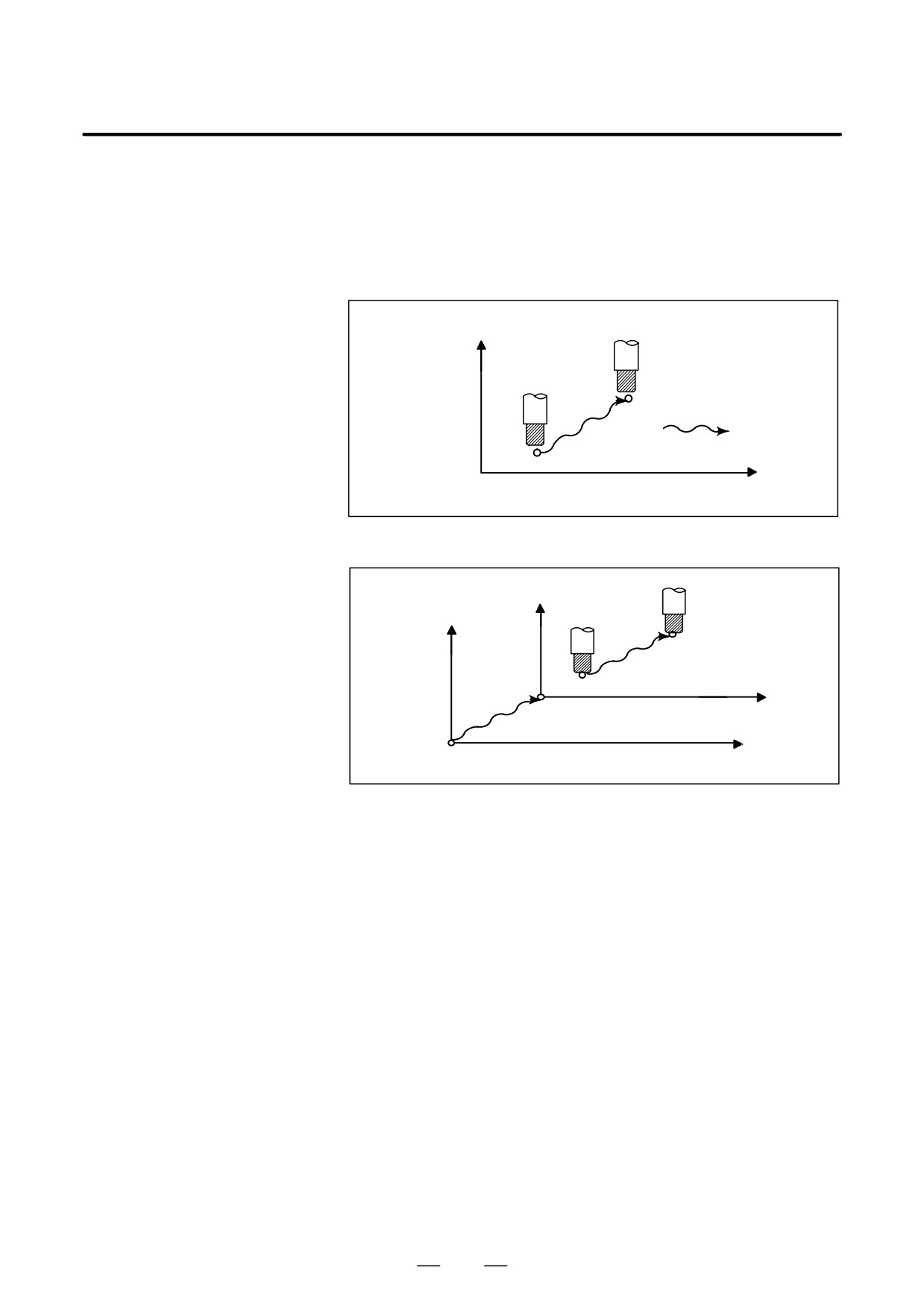
Whether the distance the tool is moved by manual operation is added to
the coordinates can be selected by turning the manual absolute switch on
MANUAL ABSOLUTE
or off on the machine operator’s panel. When the switch is turned on, the
ON AND OFF
distance the tool is moved by manual operation is added to the
coordinates. When the switch is turned off, the distance the tool is moved
by manual operation is not added to the coordinates.
Y axis
P2
Manual operation
P1
X axis
O
The coordinates values change by the amount of manual operation.
Fig. 3.5 (a) Coordinates with the switch ON
Y2
Y1
P2
O2
P1
X2
X1
O1
The coordinates do not change.
Fig. 3.5 (b) Coordinates with the switch OFF
472
B-64124EN/01
OPERATION
3. MANUAL OPERATION
Explanation
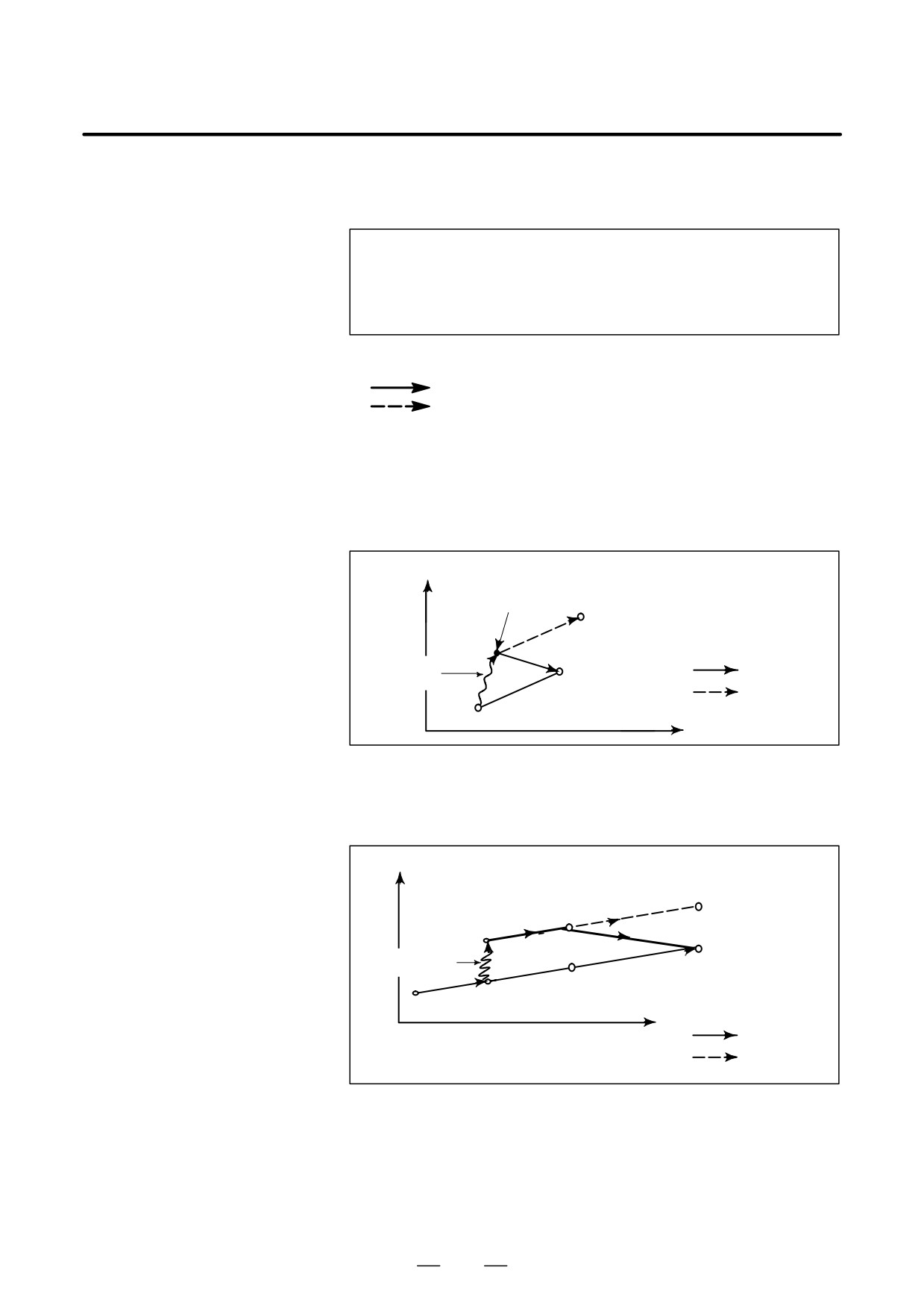
The following describes the relation between manual operation and
coordinates when the manual absolute switch is turned on or off, using a
program example.
G01G90
X100.0Y100.0F010
;
X200.0Y150.0
;
X300.0Y200.0
;
The subsequent figures use the following notation:
Movement of the tool when the switch is on
Movement of the tool when the switch is off
The coordinates after manual operation include the distance the tool is
moved by the manual operation. When the switch is off, therefore, subtract
the distance the tool is moved by the manual operation.
D Manual operation after
Coordinates when block
has been executed after manual operation
the end of block
(X-axis +20.0, Y-axis +100.0) at the end of movement of block
Y
(220.0 , 250.0)
(120.0 , 200.0)
Manual
(200.0 , 150.0)
Switch ON
operation
Switch OFF
(100.0 , 100.0)
X
D Manual operation after a
Coordinates when the feed hold button is pressed while block
is being
feed hold
executed, manual operation (Y-axis + 75.0) is performed, and the cycle
start button is pressed and released.
Y
(300.0 , 275.0)
(200.0 , 225.0)
(150.0 , 200.0)
Manual
operation
(200.0 , 150.0)
(300.0 , 200.0)
(150.0 , 125.0)
X
Switch ON
Switch OFF
473
3. MANUAL OPERATION
OPERATION
B-64124EN/01
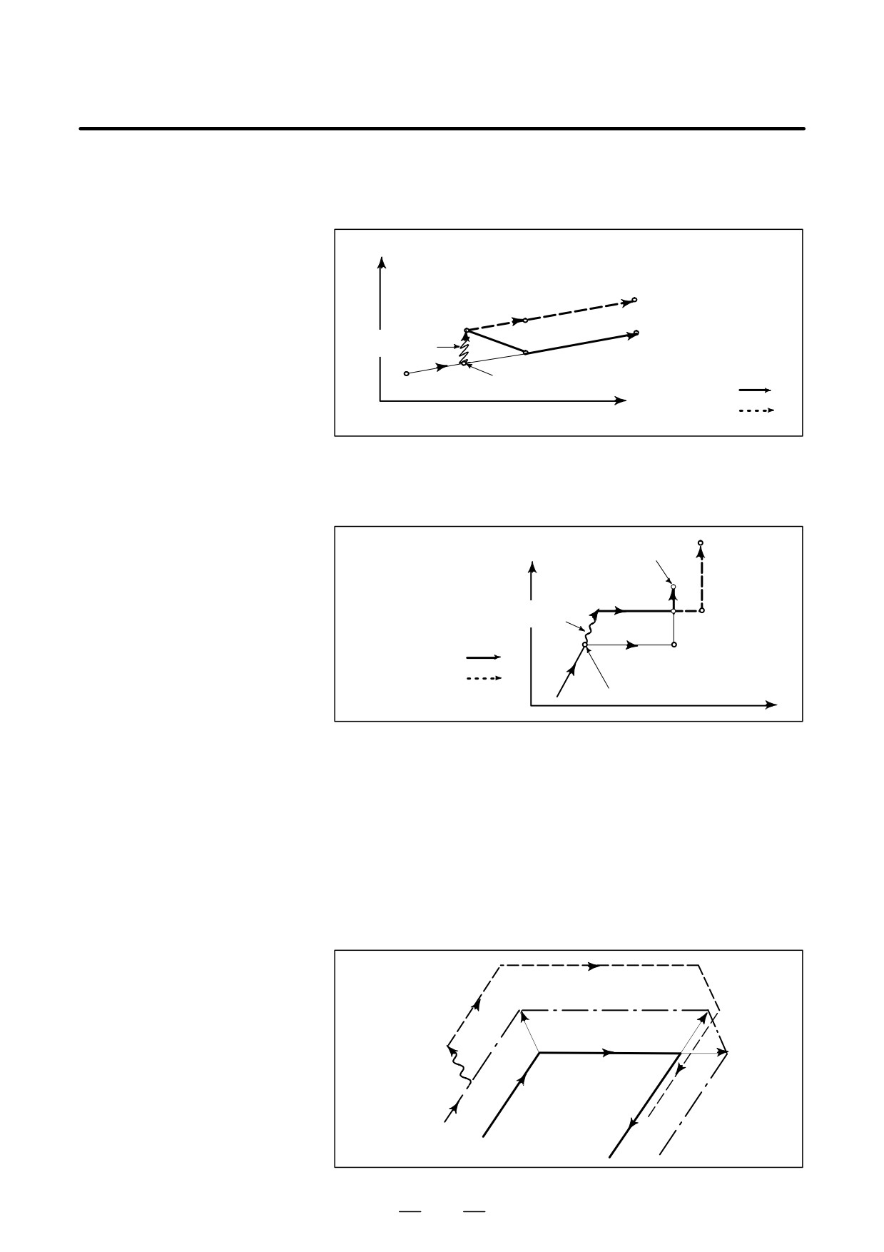
D When reset after a
Coordinates when the feed hold button is pressed while block
is being
manual operation
executed, manual operation (Y-axis +75.0) is performed, the control unit
following a feed hold
is reset with the RESET button, and block
is read again
Y
(300.0 , 275.0)
(200.0,225.0)
(150.0 , 200.0)
Manual
(300.0 , 200.0)
operation
(200.0,150.0)
(100.0 , 100.0)
(150.0 , 125.0)
Switch ON
X
Switch OFF
D When a movement
When there is only one axis in the following command, only the
command in the next
commanded axis returns.
block is only one axis
N1G01X100.0Y100.0F500;
Y
N2X200.0;
(200.0 , 150.0)
N3Y150.0;
Manual
operation
N3
Switch ON
N2
(200.0 , 100.0)
Switch OFF
N1
(100.0 , 100.0)
X
D When the next move
When the following commands are incremental commands, operation is
block is an incremental
the same as when the switch is OFF.
D Manual operation during
cutter compensation
When the switch is OFF
After manual operation is performed with the switch OFF during cutter
compensation, automatic operation is restarted then the tool moves
parallel to the movement that would have been performed if manual
movement had not been performed. The amount of separation equals to
the amount that was performed manually.
Cutter path after
manualoperation
Manual
operation
Cutter path
Programmed path
474
B-64124EN/01
OPERATION
3. MANUAL OPERATION
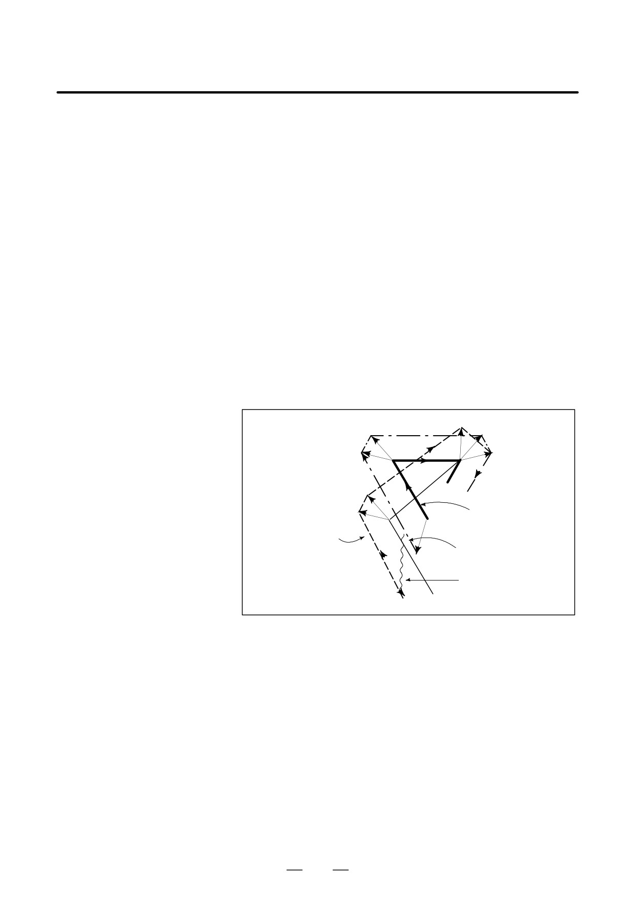
When the switch is ON during cutter compensation
Operation of the machine upon return to automatic operation after manual
intervention with the switch is ON during execution with an absolute
command program in the cutter compensation mode will be described.
The vector created from the remaining part of the current block and the
beginning of the next block is shifted in parallel. A new vector is created
based on the next block, the block following the next block and the
amount of manual movement. This also applies when manual operation
is performed during cornering.
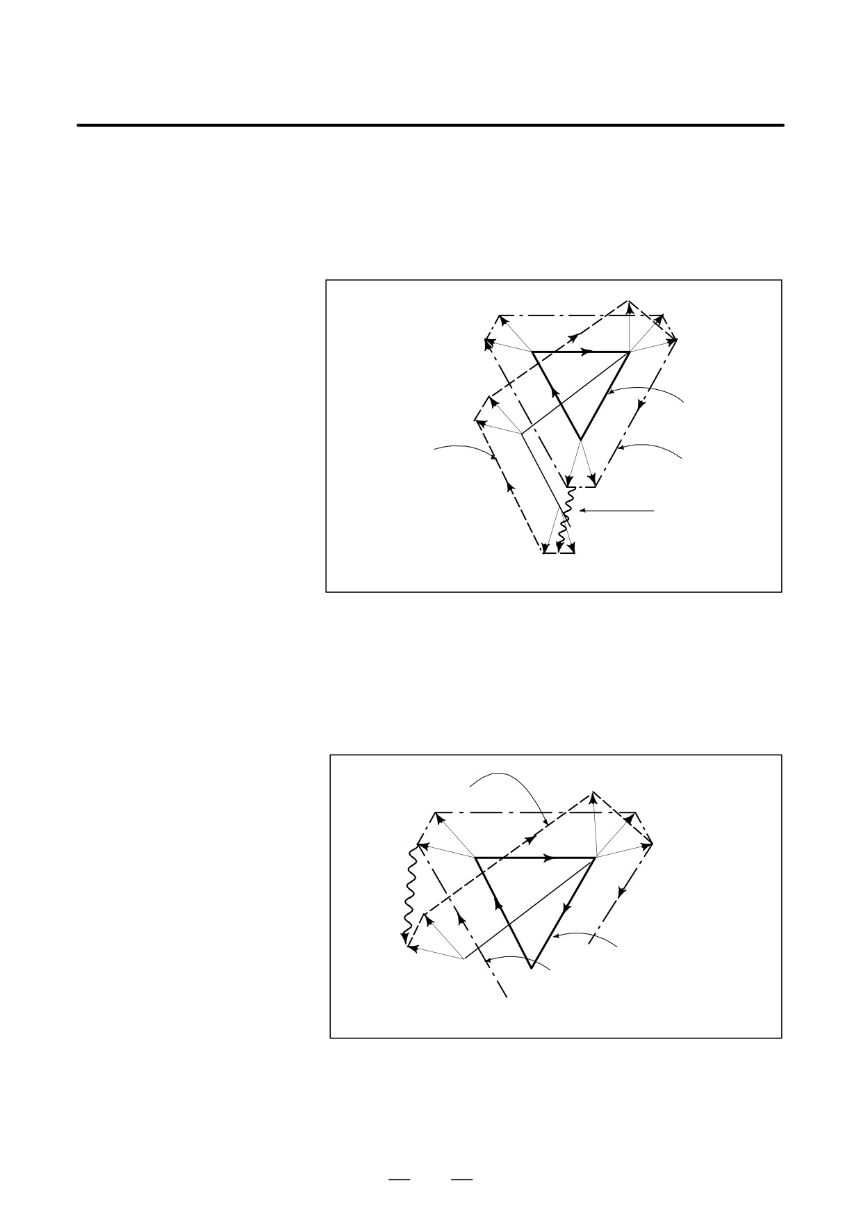
Manual operation performed in other than cornering
Assume that the feed hold was applied at point PH while moving from PA
to PB of programmed path PA, PB, and PC and that the tool was manually
moved to PH’. The block end point PB moves to the point PB’ by the
amount of manual movement, and vectors VB1 and VB2 at PB also move
to VB1’ and VB2’. Vectors VC1 and VC2 between the next two blocks PB
- PC and PC - PD are discarded and new vectors VC1’ and VC2’ (VC2’ =
VC2 in this example) are produced from the relation between PB’ - PC and
PC - PD. However, since VB2’ is not a newly calculated vector, correct
offset is not performed at block PB’ - PC. Offset is correctly performed
after PC.
VC1’
VB2
VC1
VB1
PB
PC
VC2
VB2’
PD
Programmed path
VB1’
(absolute command)
PA
Cutter path after
P’
B
P
H
manual operation
Cutter path before
manual operation
Manual operation
PH’
475
3. MANUAL OPERATION
OPERATION
B-64124EN/01
Manual operation during cornering
This is an example when manual operation is performed during cornering.
VA2’, VB1’, and VB2’ are vectors moved in parallel with VA2, VB1 and VB2
by the amount of manual movement. The new vectors are calculated
from VC1 and VC2. Then correct cutter compensation is performed for the
blocks following Pc.
VC1’
VB2
VC1
VB1
PB
PC
VC2
VB2’
VB1’
Programmed path
(absolute command)
Cutter path after
PA
manual operation
Cutter path before
manual operation
VA2
VA1
PH
PA’
Manual operation
VA2’
V
A1’
PH’
Manual operation after single block stop
Manual operation was performed when execution of a block was
terminated by single block stop.
Vectors VB1 and VB2 are shifted by the amount of manual operation.
Sub-sequent processing is the same as case a described above. An MDI
operation can also be interveneted as well as manual operation. The
movement is the same as that by manual operation.
Cutter path after
VC1’
manual operation
VB2
VC1
VB1
PB
PC
VC2
Manual
operation
VB2’
Programmed path
VB1’
PB’
(absolute command)
PA Cutter path before
manual operation
476
B-64124EN/01
OPERATION
4. AUTOMATIC OPERATION
AUTOMATIC OPERATION
4
Programmed operation of a CNC machine tool is referred to as automatic
operation.
This chapter explains the following types of automatic operation:
•
MEMORY OPERATION
Operation by executing a program registered in CNC memory
•
MDI OPERATION
Operation by executing a program entered from the MDI panel
S
DNC OPERATION
Operation while reading a program from an input/output device
•
PROGRAM RESTART
Restarting a program for automatic operation from an intermediate
point
•
SCHEDULING FUNCTION
Scheduled operation by executing programs (files) registered in an
external input/output device (such as Handy File)
•
SUBPROGRAM CALL FUNCTION
Function for calling and executing subprograms (files) registered in an
external input/output device (such as Handy File) during memory
operation
•
MANUAL HANDLE INTERRUPTION
Function for performing manual feed during movement executed by
automatic operation
•
MIRROR IMAGE
Function for enabling mirror-image movement along an axis during
automatic operation
•
MANUAL INTERVENTION AND RETURN
Function restarting automatic operation by returning the tool to the
position where manual intervention was started during automatic
operation
•
MEMORY CARD-BASED DNC OPERATION
Automatic operation by a program written to a memory card
477

4. AUTOMATIC OPERATION
OPERATION
B-64124EN/01
Programs are registered in memory in advance. When one of these
4.1
programs is selected and the cycle start switch on the machine operator’s
MEMORY
panel is pressed, automatic operation starts, and the cycle start LED goes
OPERATION
on.
When the feed hold switch on the machine operator’s panel is pressed
during automatic operation, automatic operation is stopped temporarily.
When the cycle start switch is pressed again, automatic operation is
restarted.
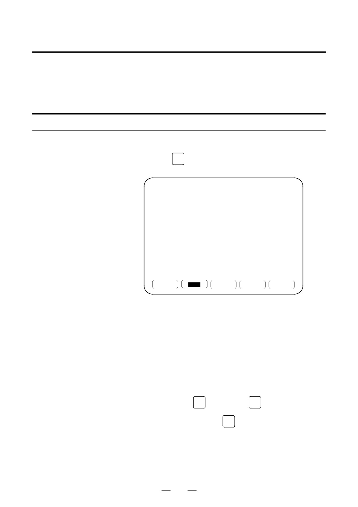
When the
RESET
key on the MDI panel is pressed, automatic operation
terminates and the reset state is entered.
The following procedure is given as an example. For actual operation,
refer to the manual supplied by the machine tool builder.
Procedure for Memory Operation
Procedure
1
Press the MEMORY mode selection switch.
2
Select a program from the registered programs. To do this, follow the
steps below.
2-1 Press
PROG
to display the program screen.
2-2 Press address
O
2-3 Enter a program number using the numeric keys.
2-4 Press the [O SRH] soft key.
3
Press the cycle start switch on the machine operator’s panel.
Automatic operation starts, and the cycle start LED goes on. When
automatic operation terminates, the cycle start LED goes off.
4
To stop or cancel memory operation midway through, follow the
steps below.
a. Stopping memory operation
Press the feed hold switch on the machine operator’s panel. The
feed hold LED goes on and the cycle start LED goes off. The
machine responds as follows:
(i) When the machine was moving, feed operation decelerates
and stops.
(ii) When dwell was being performed, dwell is stopped.
(iii) When M, S, or T was being executed, the operation is stopped
after M, S, or T is finished.
When the cycle start switch on the machine operator’s panel is
pressed while the feed hold LED is on, machine operation restarts.
478
B-64124EN/01
OPERATION
4. AUTOMATIC OPERATION
b. Terminating memory operation
Press the
RESET
key on the MDI panel.
Automatic operation is terminated and the reset state is entered.
When a reset is applied during movement, movement decelerates
then stops.
Explanation
Memory operation
After memory operation is started, the following are executed:
(1) A one-block command is read from the specified program.
(2) The block command is decoded.
(3) The command execution is started.
(4) The command in the next block is read.
(5) Buffering is executed. That is, the command is decoded to allow
immediate execution.
(6) Immediately after the preceding block is executed, execution of the
next block can be started. This is because buffering has been
executed.
(7) Hereafter, memory operation can be executed by repeating the
steps (4) to.(6)
Stopping and terminating
Memory operation can be stopped using one of two methods: Specify a
memory operation
stop command, or press a key on the machine operator’s panel.
- The stop commands include M00 (program stop), M01 (optional
stop), and M02 and M30 (program end).
- There are two keys to stop memory operation: The feed hold key
and reset key.
D Program stop (M00)
Memory operation is stopped after a block containing M00 is executed.
When the program is stopped, all existing modal information remains
unchanged as in single block operation. The memory operation can be
restarted by pressing the cycle start button. Operation may vary
depending on the machine tool builder. Refer to the manual supplied by
the machine tool builder.
D Optional stop (M01)
Similarly to M00, memory operation is stopped after a block containing
M01 is executed. This code is only effective when the Optional Stop
switch on the machine operator’s panel is set to ON. Operation may vary
depending on the machine tool builder. Refer to the manual supplied by
the machine tool builder.
D Program end
When M02 or M30 (specified at the end of the main program) is read,
(M02, M30)
memory operation is terminated and the reset state is entered.
In some machines, M30 returns control to the top of the program. For
details, refer to the manual supplied by the machine tool builder.
D Feed hold
When Feed Hold button on the operator’s panel is pressed during memory
operation, the tool decelerates to a stop at a time.
D Reset
Automatic operation can be stopped and the system can be made to the
reset state by using
RESET
key on the MDI panel or external reset signal.
When reset operation is applied to the system during a tool moving status,
the motion is slowed down then stops.
479
4. AUTOMATIC OPERATION
OPERATION
B-64124EN/01
D Optional block skip
When the optional block skip switch on the machine operator’s panel is
turned on, blocks containing a slash (/) are ignored.
Calling a subprogram
A file (subprogram) in an external input/output device such as a Floppy
stored in an external
Cassette can be called and executed during memory operation. For
input/output device
details, see Section 4.6.
480
B-64124EN/01
OPERATION
4. AUTOMATIC OPERATION
In the MDI mode, a program consisting of up to 10 lines can be created
4.2
in the same format as normal programs and executed from the MDI panel.
MDI OPERATION
MDI operation is used for simple test operations.
The following procedure is given as an example. For actual operation,
refer to the manual supplied by the machine tool builder.
Procedure for MDI Operation
Procedure
1
Press the MDI mode selection switch.
2
Press the
PROG
function key on the MDI panel to select the program
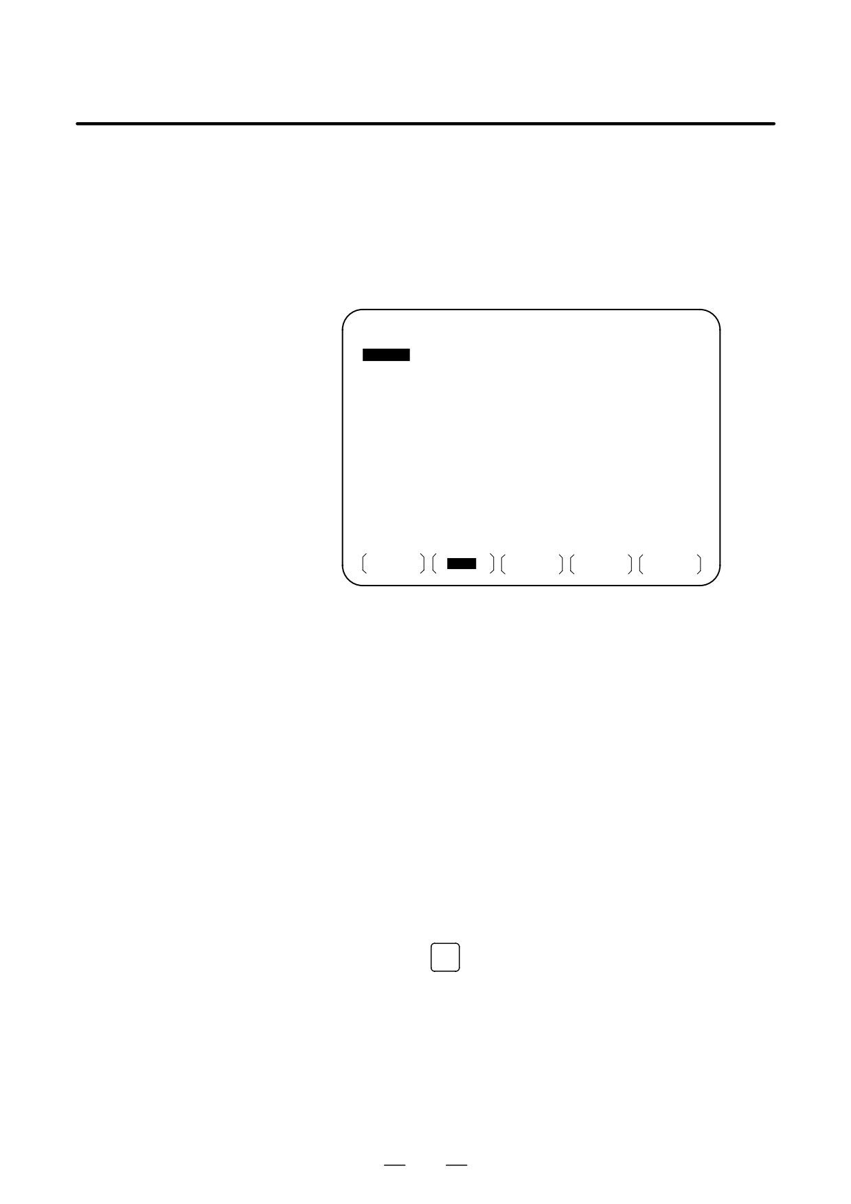
screen. The following screen appears:
PROGRAM ( MDI )
0010
00002
O0000;
G00
G90
G94
G40
G80
G50
G54
G69
G17
G22
G21
G49
G98
G67
G64
G15
B HM
T
D
F
S
>_
MDI
* * * *
* * *
* * *
20 : 40 : 05
PRGRM
MDI
CURRNT
NEXT
(OPRT)
Program number O0000 is entered automatically.
3
Prepare a program to be executed by an operation similar to normal
program editing. M99 specified in the last block can return control to
the beginning of the program after operation ends. Word insertion,
modification, deletion, word search, address search, and program
search are available for programs created in the MDI mode. For
program editing, see III-9.
4
To entirely erase a program created in MDI mode,use one of the
following methods:
a. Enter address
O
, then press the
DELETE
key on the MDI panel.
b. Alternatively, press the
RESET
key. In this case, set bit 7 of
parameter MCL No. 3203 to 1 in advance.
481
4. AUTOMATIC OPERATION
OPERATION
B-64124EN/01
5
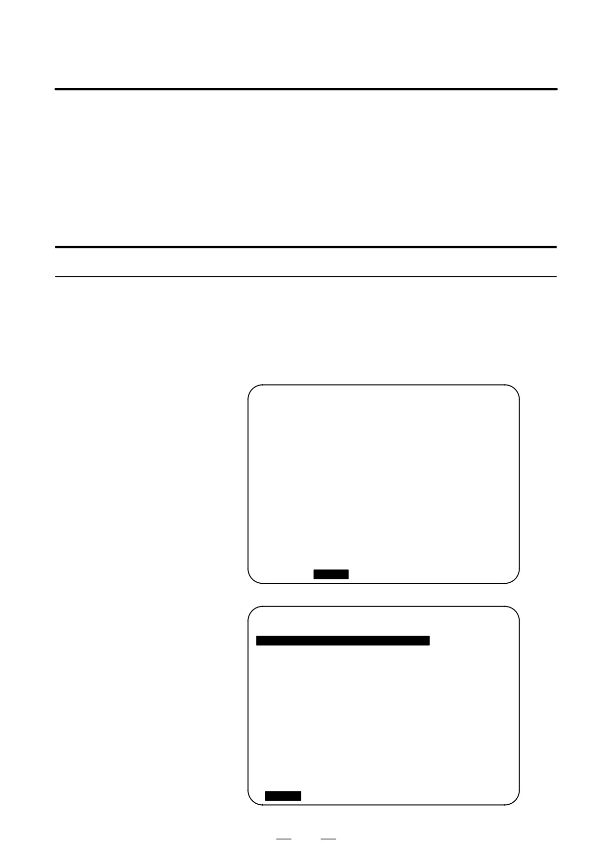
To execute a program, set the cursor on the head of the program. (Start
from an intermediate point is possible.) Push Cycle Start button on
the operator’s panel. By this action, the prepared program will start.
When the program end (M02, M30) or ER(%) is executed, the
prepared program will be automatically erased and the operation will
end.
By command of M99, control returns to the head of the prepared
program.
PROGRAM ( MDI )
O0001 N00003
O0000
G00 X100.0 Y200. ;
M03 ;
G01 Z120.0 F500 ;
M93 P9010 ;
G00 Z0.0 ;
%
G00
G90
G94
G40
G80
G50
G54
G69
G17
G22
G21
G49
G98
G67
G64
G15
B HM
T
D
F
S
>_
MDI
* * * *
* * *
* * *
12 : 42 : 39
PRGRM
MDI
CURRNT
NEXT
(OPRT)
6
To stop or terminate MDI operation in midway through, follow the
steps below.
a. Stopping MDI operation
Press the feed hold switch on the machine operator’s panel. The
feed hold LED goes on and the cycle start LED goes off. The
machine responds as follows:
(i) When the machine was moving, feed operation decelerates
and stops.
(ii) When dwell was being performed, dwell is stopped.
(iii) When M, S, or T was being executed, the operation is stopped
after M, S, or T is finished.
When the cycle start switch on the machine operator’s panel is
pressed, machine operation restarts.
b. Terminating MDI operation
Press the
RESET
key on the MDI panel.
Automatic operation is terminated and the reset state is entered.
When a reset is applied during movement, movement decelerates
then stops.
482

B-64124EN/01
OPERATION
4. AUTOMATIC OPERATION
Explanation
The previous explanation of how to execute and stop memory operation
also applies to MDI operation, except that in MDI operation, M30 does
not return control to the beginning of the program (M99 performs this
function).
D Erasing the program
Programs prepared in the MDI mode will be erased in the following cases:
S In MDI operation, if M02, M30 or ER(%) is executed.
(If bit 6 (MER) of parameter No. 3203 is set to 1, however, the
program is erased when execution of the last block of the program
is completed by single-block operation.)
S In MEMORY mode, if memory operation is performed.
S In EDIT mode, if any editing is performed.
S Background editing is performed.
S When the
O
and
DELETE
keys were pressed.
S Upon reset when bit 7 (MCL) of parameter No. 3203 is set to 1
D Restart
After the editing operation during the stop of MDI operation was done,
operation starts from the current cursor position.
D Editing a program during
A program can be edited during MDI operation. The editing of a program,
MDI operation
however, is disabled until the CNC is reset, when bit 5 (MIE) of parameter
No. 3203 is set accordingly.
Limitations
D Program registration
Programs created in MDI mode cannot be registered.
D Number of lines in a
A program can have as many lines as can fit on one page of the screen.
program
A program consisting of up to six lines can be created. When parameter
MDL (No. 3107 #7) is set to 0 to specify a mode that suppresses the
display of continuous-state information, a program of up to 10 lines can
be created.
If the created program exceeds the specified number of lines, % (ER) is
deleted (prevents insertion and modification).
D Subprogram nesting
Calls to subprograms (M98) can be specified in a program created in the
MDI mode. This means that a program registered in memory can be
called and executed during MDI operation. In addition to the main
program executed by automatic operation, up to four levels of
subprogram nesting are allowed.
Main program
Subprogram
Subprogram
O0000;
O1000;
O2000;
M98P 1000;
M98P 2000;
M98P 3000;
M30;
M99;
M99;
One-level nesting
Two-level nesting
Fig. 4.2 Nesting level of subprograms called from the MDI program
483
4. AUTOMATIC OPERATION
OPERATION
B-64124EN/01
D Macro call
Macro programs can also be created, called, and executed in the MDI
mode. However, macro call commands cannot be executed when the
mode is changed to MDI mode after memory operation is stopped during
execution of a subprogram.
D Memory area
When a program is created in the MDI mode, an empty area in program
memory is used. If program memory is full, no programs can be created
in the MDI mode.
484
B-64124EN/01
OPERATION
4. AUTOMATIC OPERATION
4.3
By activating automatic operation during the DNC operation mode
(RMT), it is possible to perform machining (DNC operation) while a
DNC OPERATION
program is being read in via reader/puncher interface, or remote buffer.
It is possible to select files (programs) saved in an external input/output
unit of a floppy format (such as Handy File) and specify (schedule) the
sequence and frequency of execution for automatic operation. (see
III-4.5)
To use the DNC operation function, it is necessary to set the parameters
related to the reader/punch interface, and remote buffer in advance.
DNC OPERATION
Procedure
1
Search for the program (file) to be executed.
2
Press the REMOTE switch on the machine operator’s panel to set
RMT mode, then press the cycle start switch. The selected file is
executed. For details of the use of the REMOTE switch, refer to the
relevant manual supplied by the machine tool builder.
D Program check screen
PROGRAM CHECK
O0001 N00020
O0010 ;
G92 G90 X100 Y200 Z50 ;
G00 X0 Y0 Z0 ;
G01 Z250 F1000
(RELATIVE)
(DIST TO GO) G00
G94
G80
X
100.000
X
0.000
G17
G21
G98
Y
100.000
Y
0.000
G90
G49
G80
Z
0.000 Z
0.000
G22
G49
G67
A
0.000 A
0.000
B
C
0.000 C
0.000 H
M
HD.T
NX.T
D M
F
S
M
ACT.F
SACT
REPEAT
RMT STRT MTN *** ***
21:20:05
[ ABS
]
[ REL
]
[
]
[
]
[
(OPRT) ]
D Program screen
PROGRAM
O0001 N00020
N020 X100.0 Z100.0 (DNC-PROG) ;
N030
X200.0
Z200.0 ;
N040
X300.0
Z300.0 ;
N050
X400.0
Z400.0 ;
N060
X500.0
Z500.0 ;
N070
X600.0
Z600.0 ;
N080
X700.0
Z400.0 ;
N090
X800.0
Z400.0 ;
N100
x900.0
z400.0 ;
N110
x1000.0
z1000.0 ;
N120
x800.0
z800.0 ;
RMT STRT MTN *** ***
21:20:05
[
PRGRM ] [ CHECK ] [
]
[
]
[
(OPRT) ]
485

4. AUTOMATIC OPERATION
OPERATION
B-64124EN/01
During DNC operation, the program currently being executed is
displayed on the program check screen and program screen.
The number of displayed program blocks depends on the program being
executed.
Any comment enclosed between a control-out mark “(” and control-in
mark “)” within a block is also displayed.
Explanations
D During DNC operation, programs stored in memory can be called.
D During DNC operation, macro programs stored in memory can be
called.
Limitations
D Limit on number of
In program display, no more than 256 characters can be displayed.
characters
Accordingly, character display may be truncated in the middle of a block.
D M198 (command for
In DNC operation, M198 cannot be executed. If M198 is executed, P/S
calling a program from
alarm No. 210 is issued.
within an external
input/output unit)
D Custom macro
In DNC operation, custom macros can be specified, but no repeat
instruction and branch instruction can be programmed. If a repeat
instruction or branch instruction is executed, P/S alarm No. 123 is issued.
When reserved words (such as IF, WHILE, COS, and NE) used with
custom macros in DNC operation are displayed during program display,
a blank is inserted between adjacent characters.
Example
[During DNC operation]
#102=SIN[#100] ;
→
#102 = S I N[#100] ;
IF[#100NE0]GOTO5 ;
→
I F[#100NE0] G O T O 5 ;
D M99
When control is returned from a subprogram or macro program to the
calling program during DNC operation, it becomes impossible to use a
return command (M99P****) for which a sequence number is specified.
Alarm
Number
Message
Contents
086
DR SIGNAL OFF
When entering data in the memory by
using Reader / Puncher interface, the
ready signal (DR) of reader / puncher
was turned off.
Power supply of I/O unit is off or cable is
not connected or a P.C.B. is defective.
123
CAN NOT USE MACRO
Macro control command is used during
COMMAND IN DNC
DNC operation.
Modify the program.
210
CAN NOT COMAND
Or M198 is executed in the DNC opera-
M198/M199
tion. Modify the program.
486
B-64124EN/01
OPERATION
4. AUTOMATIC OPERATION
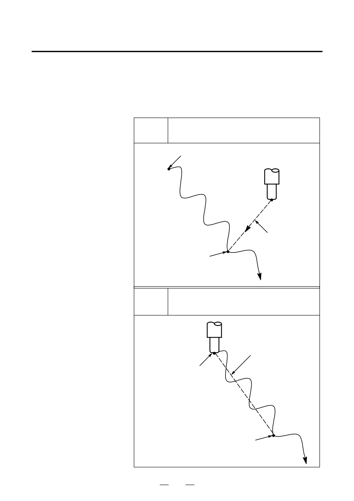
This function specifies Sequence No. of a block to be restarted when a tool
4.4
is broken down or when it is desired to restart machining operation after
PROGRAM
a day off, and restarts the machining operation from that block. It can also
RESTART
be used as a high-speed program check function.
There are two restart methods: the P-type method and Q-type method.
Operation can be restarted anywhere. This restart method is
P TYPE
used when operation is stopped because of a broken tool.
Program start point (machining start point)
ÇÇ
ÇÇ
Return operation
Restart position
Before operation can be restarted, the machine must be moved
Q TYPE
to the programmed start point (machining start point)
ÇÇ
ÇÇ
Return operation
ÇÇ
Program start point
(machining start point)
Restart position
487
4. AUTOMATIC OPERATION
OPERATION
B-64124EN/01
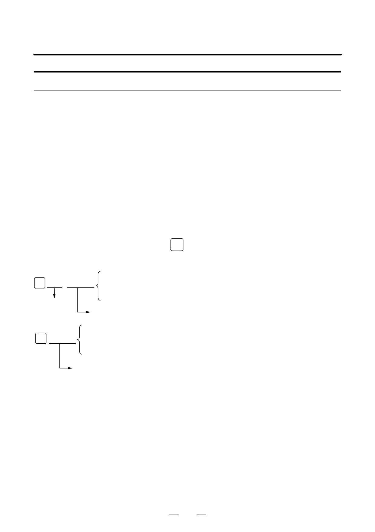
Procedure for Program Restart by Specifying a Sequence Number
Procedure 1
[ P TYPE ]
1
Retract the tool and replace it with a new one. When necessary,
change the offset.
(Go to step 2.)
[ Q TYPE ]
1
When power is turned ON or emergency stop is released, perform all
necessary operations at that time, including the reference position
return.
2
Move the machine manually to the program starting point (machining
start point), and keep the modal data and coordinate system in the
same conditions as at the machining start.
3
If necessary, modify the offset amount.
Procedure 2
[COMMON TO P TYPE /
1
Turn the program restart switch on the machine operator’s panel ON.
Q TYPE]
2
Press
PROG
key to display the desired program.
3
Find the program head.
[Q TYPE]
4
Enter the sequence number of the block to be restarted, then press th
N
fff
fffff
[P TYPE] or [Q TYPE] soft key.
or
[P TYPE]
Frequency
Sequence number
[Q TYPE]
If the same sequence number appears more than once, the location of
N
fffff
or
the target block must be specified. Specify a frequency and a
sequence number.
[P TYPE]
Sequence number
488
B-64124EN/01
OPERATION
4. AUTOMATIC OPERATION
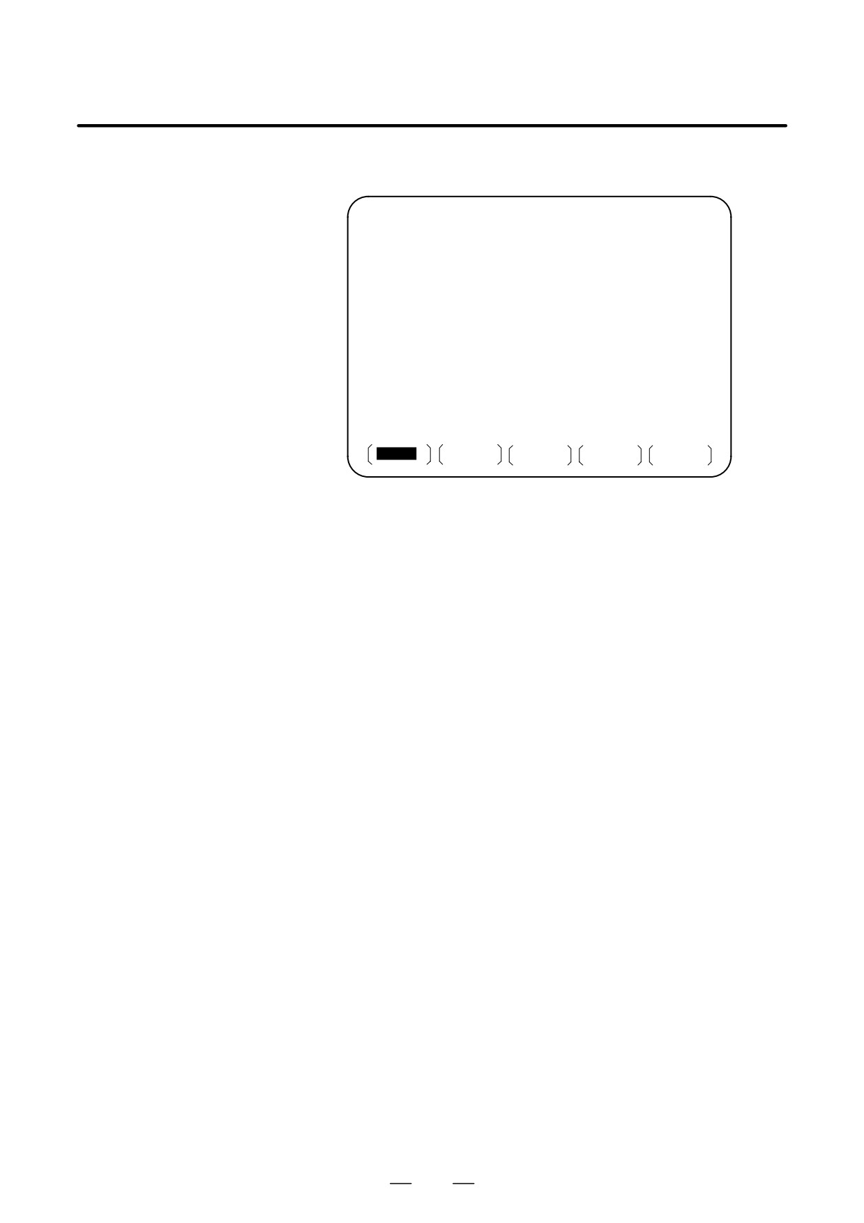
5
The sequence number is searched for, and the program restart screen
appears on the CRT display.
PROGRAM RESTART
O0002 N01000
DESTINATION
M
1
2
X 57. 096
1
2
Y 56. 877
1
2
Z 56. 943
1
2
1
2
1 * * * * * * * *
* * * * * * * ** * * * * * * *
DISTANCE TO GO
1 X 1. 459
T * * * * * * * ** * * * * * * *
2 Y 10. 309
S * * * * *
3 Z 7. 320
S
0 T0000
MEM * * * *
* * *
* * *
10 : 10 : 40
RSTR
DIR
(OPRT)
DESTINATION shows the position at which machining is to restart.
DISTANCE TO GO shows the distance from the current tool position
to the position where machining is to restart. A number to the left of
each axis name indicates the order of axes (determined by parameter
setting) along which the tool moves to the restart position.
The coordinates and amount of travel for restarting the program can
be displayed for up to five axes. If your system supports six or more
axes, pressing the [RSTR] soft key again displays the data for the
sixth and subsequent axes. (The program restart screen displays only
the data for CNC-controlled axes.)
M: Fourteen most recently specified M codes
T: Two most recently specified T codes
S: Most recently specified S code
B: Most recently specified B code
Codes are displayed in the order in which they are specified. All
codes are cleared by a program restart command or cycle start in the
reset state.
6
Turn the program re-start switch OFF. At this time, the figure at the
left side of axis name DISTANCE TO GO blinks.
7
Check the screen for the M, S, T, and B codes to be executed. If they
are found, enter the MDI mode, then execute the M, S, T, and B
functions. After execution, restore the previous mode.
These codes are not displayed on the program restart screen.
8
Check that the distance indicated under DISTANCE TO GO is correct.
Also check whether there is the possibility that the tool might hit a
workpiece or other objects when it moves to the machining restart
position. If such a possibility exists, move the tool manually to a
position from which the tool can move to the machining restart
position without encountering any obstacles.
9
Press the cycle start button. The tool moves to the machining restart
position at the dry run feedrate sequentially along axes in the order
specified by parameter settings (No. 7310). Machining is then
restarted.
489
4. AUTOMATIC OPERATION
OPERATION
B-64124EN/01
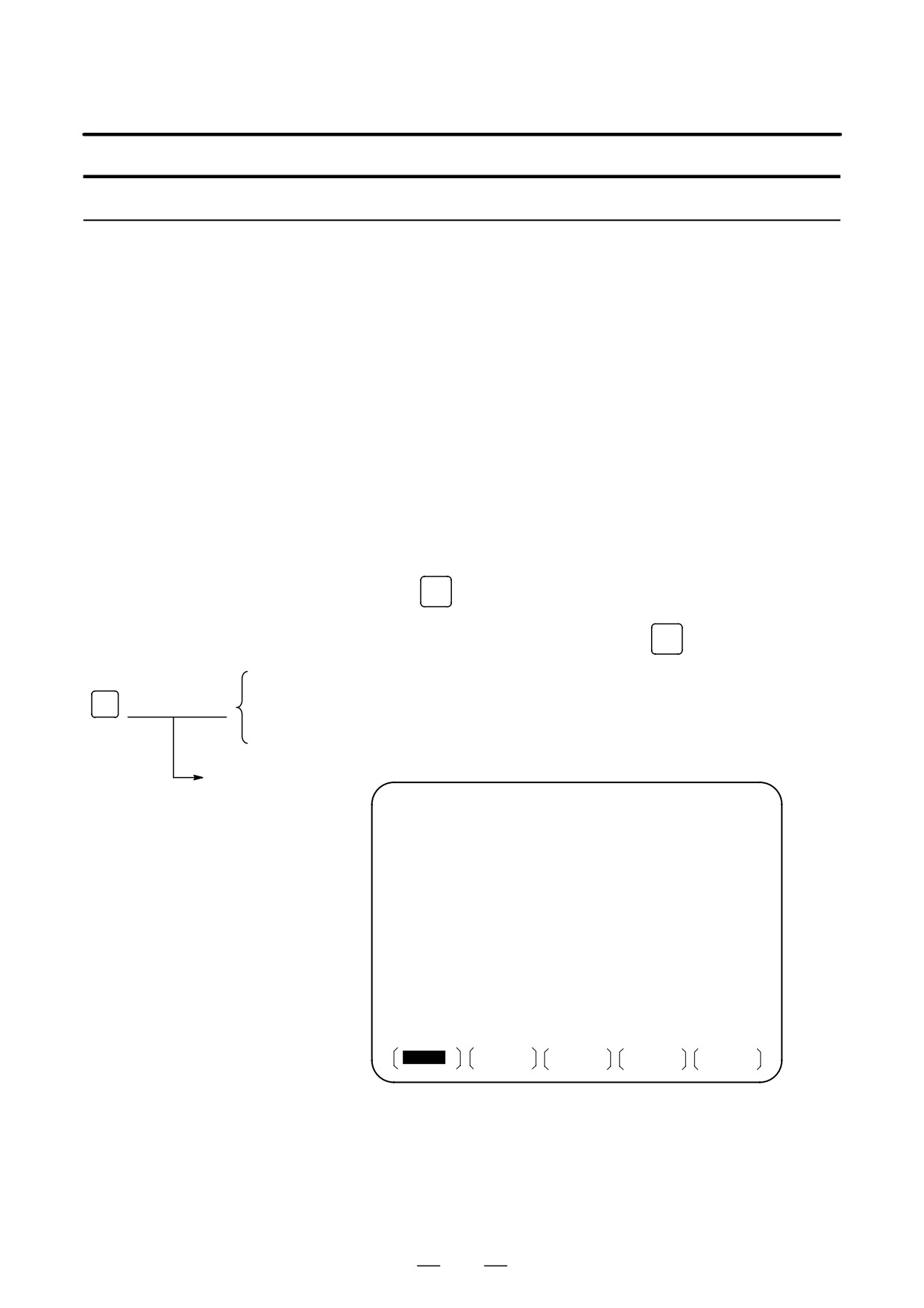
Procedure for Program Restart by Specifying a Block Number
Procedure 1
[ P TYPE ]
1
Retract the tool and replace it with a new one. When necessary,
change the offset.
(Go to step 2.)
[ Q TYPE ]
1
When power is turned ON or emergency stop is released, perform all
necessary operations at that time, including the reference position
return.
2
Move the machine manually to the program starting point (machining
start point), and keep the modal data and coordinate system in the
same conditions as at the machining start.
3
If necessary, modify the offset amount.
Procedure 2
[COMMON TO P TYPE /
1
Turn the program restart switch on the machine operator’s panel ON.
Q TYPE]
2
Press
PROG
key to display the desired program.
3
Find the program head. Press function
RESET
key.
[Q TYPE]
4
Enter the number of the block to be restarted then press the [P TYPE]
or [Q TYPE] soft key. The block number cannot exceed eight digits.
B
f f f f f f f f
or
[P TYPE]
5
The block number is searched for, and the program restart screen
appears on the display.
Block number
PROGRAM RESTART
O0002 N01000
DESTINATION
M
1
2
X 57. 096
1
2
Y 56. 877
1
2
Z 56. 943
1
2
1
2
1 * * * * * * * *
DISTANCE TO GO
* * * * * * * ** * * * * * * *
X 1. 459
T * * * * * * * ** * * * * * * *
Y 10. 309
Z 7. 320
S * * * * *
S
0 T0000
MEM * * * *
* * *
* * *
10 : 10 : 40
RSTR
DIR
FL.SDL
(OPRT)
DESTINATION shows the position at which machining is to restart.
DISTANCE TO GO shows the distance from the current tool position
to the position where machining is to restart. A number to the left of
each axis name indicates the order of axes (determined by parameter
setting) along which the tool moves to the restart position.
490

B-64124EN/01
OPERATION
4. AUTOMATIC OPERATION
The coordinates and amount of travel for restarting the program can
be displayed for up to five axes. If your system supports six or more
axes, pressing the [RSTR] soft key again displays the data for the
sixth and subsequent axes. (The program restart screen displays only
the data for CNC-controlled axes.)
M: Fourteen most recently specified M codes
T: Two most recently specified T codes
S: Most recently specified S code
B: Most recently specified B code
Codes are displayed in the order in which they are specified. All
codes are cleared by a program restart command or cycle start in the
reset state.
6
Turn the program re-start switch OFF. At this time, the figure at the
left side of axis name DISTANCE TO GO blinks.
7
Check the screen for the M, S, T, and B codes to be executed. If they
are found, enter the MDI mode, then execute the M, S, T, and B
functions. After execution, restore the previous mode.
These codes are not displayed on the program restart screen.
8
Check that the distance indicated under DISTANCE TO GO is correct.
Also check whether there is the possibility that the tool might hit a
workpiece or other objects when it moves to the machining restart
position. If such a possibility exists, move the tool manually to a
position from which the tool can move to the machining restart
position without encountering any obstacles.
9
Press the cycle start button. The tool moves to the machining restart
position at the dry run feedrate sequentially along axes in the order
specified by parameter settings (No. 7310). Machining is then
restarted.
Explanations
D Block number
When the CNC is stopped, the number of executed blocks is displayed on
the program screen or program restart screen. The operator can specify
the number of the block from which the program is to be restarted, by
referencing the number displayed on the CRT. The displayed number
indicates the number of the block that was executed most recently. For
example, to restart the program from the block at which execution
stopped, specify the displayed number, plus one.
The number of blocks is counted from the start of machining, assuming
one NC line of a CNC program to be one block.
< Example 1 >
CNC Program
Number of blocks
O 0001 ;
1
G90 G92 X0 Y0 Z0 ;
2
G01 X100. F100 ;
3
G03 X01 -50. F50 ;
4
M30 ;
5
491
4. AUTOMATIC OPERATION
OPERATION
B-64124EN/01
< Example 2 >
CNC Program
Number of blocks
O 0001 ;
1
G90 G92 X0 Y0 Z0 ;
2
G90 G00 Z100. ;
3
G81 X100. Y0. Z-120. R-80. F50. ;
4
#1 = #1 + 1 ;
4
#2 = #2 + 1 ;
4
#3 = #3 + 1 ;
4
G00 X0 Z0 ;
5
M30 ;
6
Macro statements are not counted as blocks.
D Storing / clearing the
The block number is held in memory while no power is supplied. The
block number
number can be cleared by cycle start in the reset state.
D Block number when a
The program screen usually displays the number of the block currently
program is halted or
being executed. When the execution of a block is completed, the CNC
stopped
is reset, or the program is executed in single-block stop mode, the
program screen displays the number of the program that was executed
most recently.
When a CNC program is halted or stopped by feed hold, reset, or
single-block stop, the following block numbers are displayed:
Feed hold : Block being executed
Reset : Block executed most recently
Single-block stop : Block executed most recently
For example, when the CNC is reset during the execution of block 10, the
displayed block number changes from 10 to 9.
D MDI intervention
When MDI intervention is performed while the program is stopped by
single-block stop, the CNC commands used for intervention are not
counted as a block.
D Block number exceeding
When the block number displayed on the program screen exceeds eight
eight digits
digits, the block number is reset to 0 and counting continues.
Limitations
D P-type restart
Under any of the following conditions, P-type restart cannot be
performed:
⋅
When automatic operation has not been performed since the power
was turned on
⋅
When automatic operation has not been performed since an
emergency stop was released
⋅
When automatic operation has not been performed since the
coordinate system was changed or shifted (change in an external
offset from the workpiece reference point)
D Restart block
The block to be restarted need not be the block which was interrupted;
operation can restart with any block. When P-type restart is performed,
the restart block must use the same coordinate system as when operation
was interrupted.
492