FANUC Series 0i-MC. OPERATOR’S MANUAL - page 13
B-64124EN/01
PROGRAMMING
15. CUSTOM MACRO
D When the next block
involves no movement in
> N1 G01 G41 X100.0 G100 Dd ;
cutter compensation C
N2 #1=100 ;
(G41, G42) mode
> : Block being executed
N3 Y100.0 ;
j : Blocks read into the buffer
N4 #2=200 ;
N5 M08 ;
N6 #3=300 ;
N7 X200.0 ;
:
N1
N3
NC statement
execution
N2
N4
N6
Macro statement
execution
N3
N5
N7
Buffer
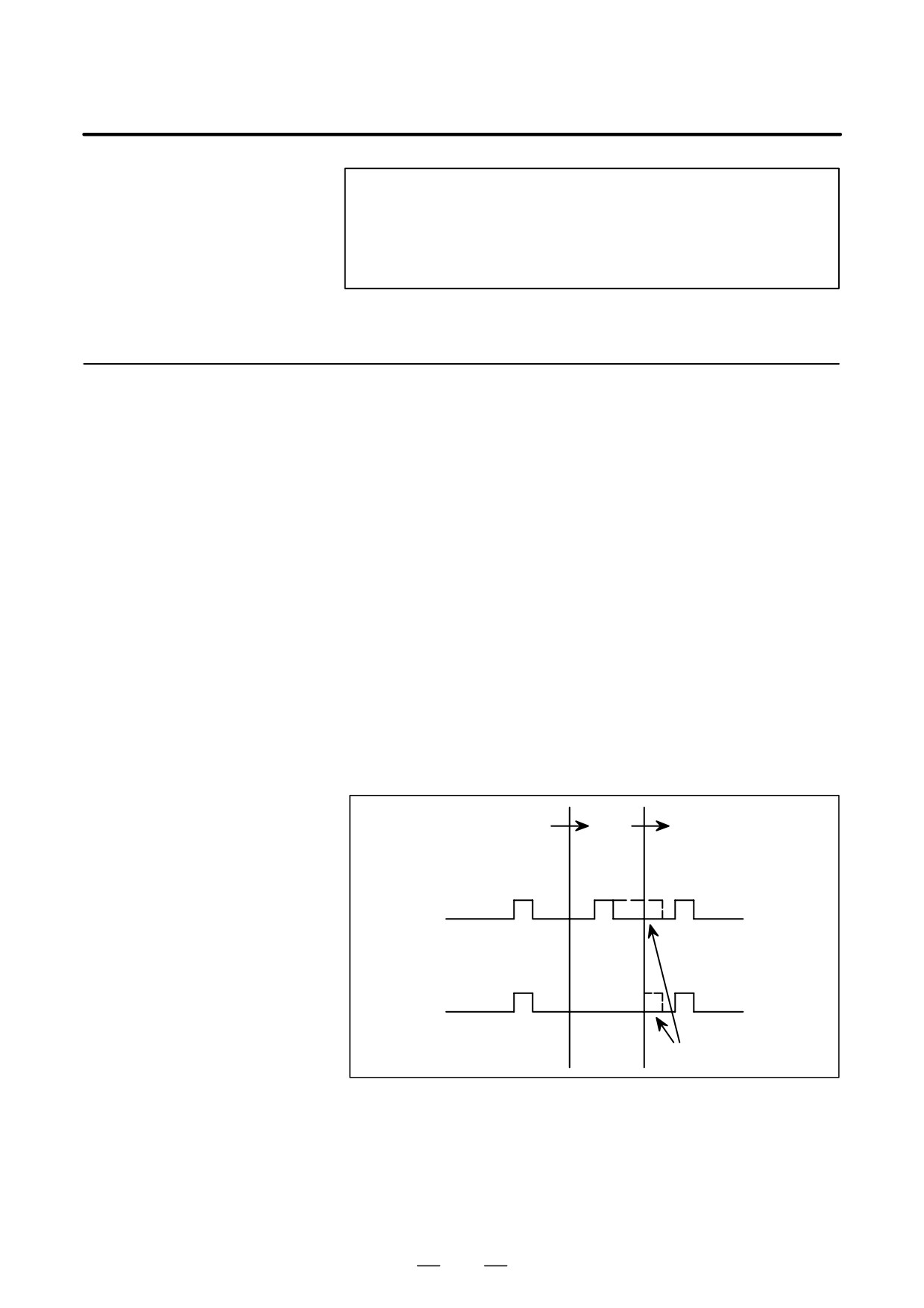
When the N1 is being executed, the NC statements in the next two blocks
(up to N5) are read into the buffer. Since N5 is a block that involves no
movement, an intersection cannot be calculated. In this case, the NC
statements in the next three blocks (up to N7) are read. The macro
statements (N2, N4, and N6) between N1 and N7 are processed during
execution of N1.
In case of using the following system variables (Table 15.7.2) in macro
15.7.2
program and you need to execute the macro program after completing the
Caution for using
block execution just before the macro program, M code which can prevent
system variables
buffering (parameter No.3411-3432) or G53 command block is necessary
just before the macro program.
Table 15.7.2
Meaning
Read
Number of
Note
Write
Variable
(In case not to
command M code
preventing buffering or
G53 block.)
Interface sig-
Read
#1000 - #1015 ,
The data is read at
nals
#1032
buffering a macro
program.
Write
#1100 - #1115 ,
The data is written at
#1132
buffering a macro
program.
Tool com-
Write
#10001 -
The data is written at
pensation val-
buffering a macro
ues
program.
Macro alarms
Write
#3000
Macro alarm is
generated at maximum
2 blocks before a macro
program.
343

15. CUSTOM MACRO
PROGRAMMING
B-64124EN/01
Table 15.7.2
Meaning
Read
Number of
Note
Write
Variable
(In case not to
command M code
preventing buffering or
G53 block.)
Program stop
Write
#3006
Program stops at
with
maximum 2 blocks
message
before a macro
program.
Time informa-
Read
#3001,#3002
The data is read / written
tion
Write
at buffering a macro
program.
Read
#3011,#3012
The data is read at
buffering a macro
program.
Automatic op-
Write
#3003, #3004
Setting data is available
eration control
at maximum 2 blocks
before a macro
program.
Settings
Write
#3005
The data is written at
buffering a macro
program.
Mirror image
Read
#3007
The data is read at
buffering a macro
program.
Currently se-
Read
#4130(P)
The data is read at
lected
#4014
maximum 3 blocks
additional
(G54 - G59)
before a macro
workpiece
program.
coordinate
system
Current posi-
Read
#5021 - #5028
The uncertain position in
tion
moving is read.
(Machine
coordinate
system)
Current posi-
Read
#5041 - #5048
The uncertain position in
tion
moving is read.
(Workpiece
coordinate
system)
Tool length
Read
#5081 - #5088
The offset value of
offset value
current execution block
is read.
Deviated ser-
Read
#5101 - #5108
The uncertain deviation
vo position
in moving is read.
Workpiece
Write
#5201 - #5328
The data is written at
zero point off-
#7001 - #7948
buffering a macro
set value
program.
344
B-64124EN/01
PROGRAMMING
15. CUSTOM MACRO
Example)
O0001
O2000
N1 X10.Y10.;
(Mxx ;) Specify preventing buffering M code or G53
N2 M98P2000;
N100 #1=#5041; (Reading X axis current position)
N3 Y200.0;
N101 #2=#5042; (Reading Y axis current position)
:
:
M99;
In above case, the buffering of N2 block is done and the macro program
of O2000 is read and executed during N1 block of main program O1000
execution. Therefore, the current position readings are executed during
axes movements at N1 block. So the unexpected position data can be read
to #1 and #2 because of axes movements. In this case, please specify M
code preventing buffering Mxx ; (or G53 ;) just before N100 block of
O2000. By this, the position data at completing the execution of N1 block
can be read to #1 and #2 because O2000 is executed after completing the
execution of N1 block of O0001.
NOTE
G53 can not be specified during the canned cycle mode. (In
this case, the P/S alarm No.44 is generated.) Therefore, in
order to prevent buffering during the canned cycle mode,
please specify preventing buffering M code.
345
15. CUSTOM MACRO
PROGRAMMING
B-64124EN/01
Custom macro programs are similar to subprograms. They can be
15.8
registered and edited in the same way as subprograms. The storage
REGISTERING
capacity is determined by the total length of tape used to store both custom
CUSTOM MACRO
macros and subprograms.
PROGRAMS
346
B-64124EN/01
PROGRAMMING
15. CUSTOM MACRO
15.9
LIMITATIONS
D MDI operation
The macro call command can be specified in MDI mode. During
automatic operation, however, it is impossible to switch to the MDI mode
for a macro program call.
D Sequence number
A custom macro program cannot be searched for a sequence number.
search
D Single block
Even while a macro program is being executed, blocks can be stopped in
the single block mode.
A block containing a macro call command (G65, G66, or G67) does not
stop even when the single block mode is on. Blocks containing arithmetic
operation commands and control commands can be stopped in single
block mode by setting SBM (bit 5 of parameter 6000) to 1.
Single block stop operation is used for testing custom macro programs.
Note that when a single block stop occurs at a macro statement in cutter
compensation C mode, the statement is assumed to be a block that does
not involve movement, and proper compensation cannot be performed in
some cases.
(Strictly speaking, the block is regarded as specifying a
movement with a travel distance 0.)
D Optional block skip
A / appearing in the middle of an <expression> (enclosed in brackets [
] on the right-hand side of an arithmetic expression) is regarded as a
division operator; it is not regarded as the specifier for an optional block
skip code.
By setting NE8 (bit 0 of parameter 3202) and NE9 (bit 4 of parameter
D Operation in EDIT mode
3202) to 1, deletion and editing are disabled for custom macro programs
and subprograms with program numbers 8000 to 8999 and 9000 to 9999.
This prevents registered custom macro programs and subprograms from
being destroyed by accident. When the entire memory is cleared (by
pressing the
RESET
and
DELETE
keys at the same time to turn on the power),
the contents of memory such as custom macro programs are deleted.
D Reset
With a reset operation, local variables and common variables #100 to
#149 are cleared to null values. They can be prevented from clearing by
setting, CLV and CCV (bits 7 and 6 of parameter 6001). System variables
#1000 to #1133 are not cleared.
A reset operation clears any called states of custom macro programs and
subprograms, and any DO states, and returns control to the main program.
D Display of the PROGRAM
As with M98, the M and T codes used for subprogram calls are not
RESTART
displayed.
D Feed hold
When a feed hold is enabled during execution of a macro statement, the
machine stops after execution of the macro statement. The machine also
stops when a reset or alarm occurs.
D Constant values that can
+0.0000001 to +99999999
be used in <expression>
-99999999 to -0.0000001
The number of significant digits is 8 (decimal). If this range is exceeded,
P/S alarm No. 003 occurs.
347
15. CUSTOM MACRO
PROGRAMMING
B-64124EN/01
In addition to the standard custom macro commands, the following macro
15.10
commands are available. They are referred to as external output
EXTERNAL
OUTPUT
commands.
COMMANDS
- BPRNT
- DPRNT
- POPEN
- PCLOS
These commands are provided to output variable values and characters
through the reader/punch interface.
Explanations
Specify these commands in the following order:
Open command: POPEN
Before specifying a sequence of data output commands, specify this
command to establish a connection to an external input/output device.
Data output command: BPRNT or DPRNT
Specify necessary data output.
Close command: PCLOS
When all data output commands have completed, specify PCLOS to
release a connection to an external input/output device.
D Open command POPEN
POPEN
POPEN establishes a connection to an external input/output device. It
must be specified before a sequence of data output commands. The CNC
outputs a DC2 control code.
D Data output command
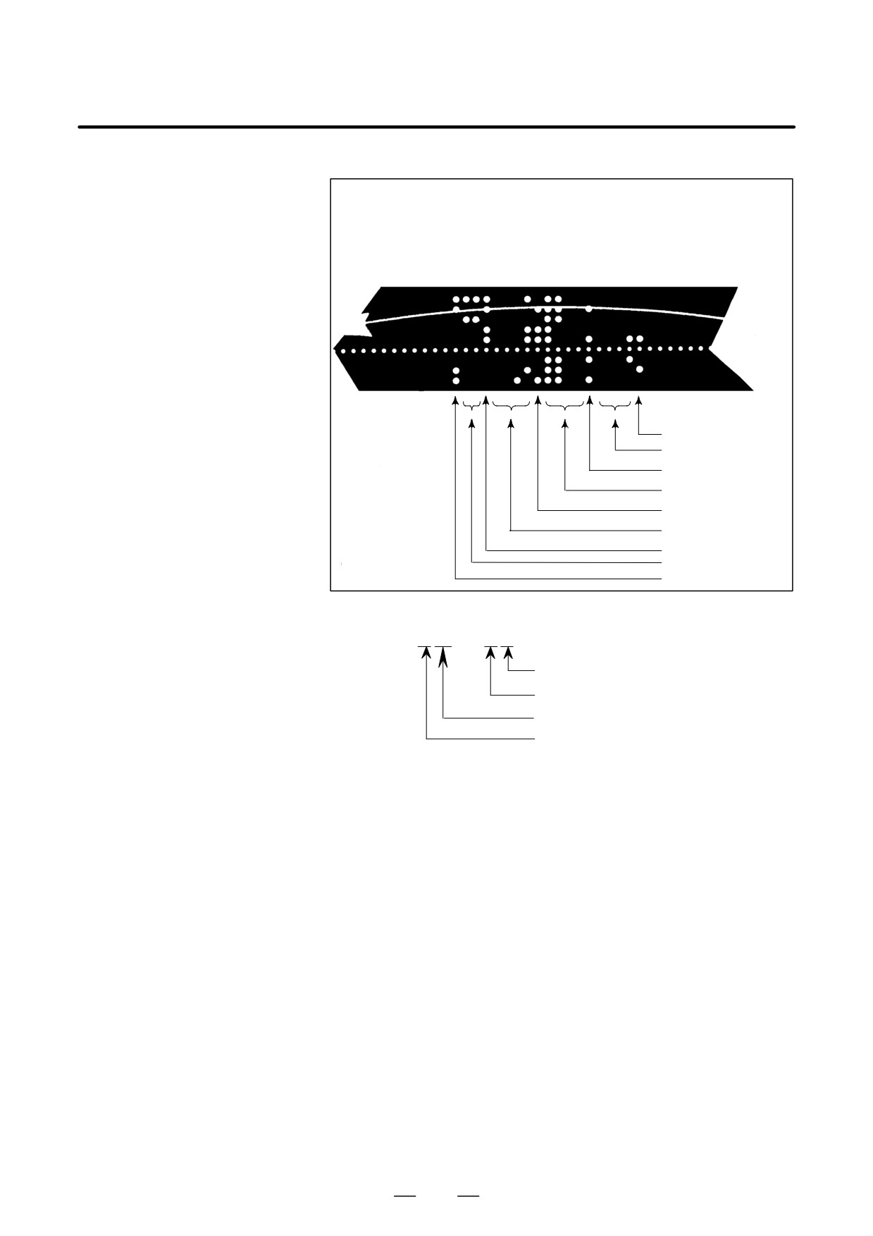
BPRNT
BPRNT [ a #b
[ c ]
… ]
Number of significant decimal places
Variable
Character
The BPRNT command outputs characters and variable values in binary.
(i) Specified characters are converted to the codes according to the
setting data (ISO) that is output at that time.
Specifiable characters are as follows:
- Letters (A to Z)
- Numbers
- Special characters (*, /, +, -, etc.)
An asterisk (*) is output by a space code.
(ii) All variables are stored with a decimal point. Specify a variable
followed by the number of significant decimal places enclosed in
brackets. A variable value is treated as 2-word (32-bit) data,
including the decimal digits. It is output as binary data starting from
the highest byte.
(iii) When specified data has been output, an EOB code is output
according to the setting code (ISO).
(iv) Null variables are regarded as 0.
348
B-64124EN/01
PROGRAMMING
15. CUSTOM MACRO
Example )
BPRNT [ C** X#100 [3] Y#101 [3] M#10 [0] ]
Variable value
#100=0.40956
#101=-1638.4
#10=12.34
LF
12 (0000000C)
M
-1638400(FFE70000)
Y
410 (0000019A)
X
Space
C
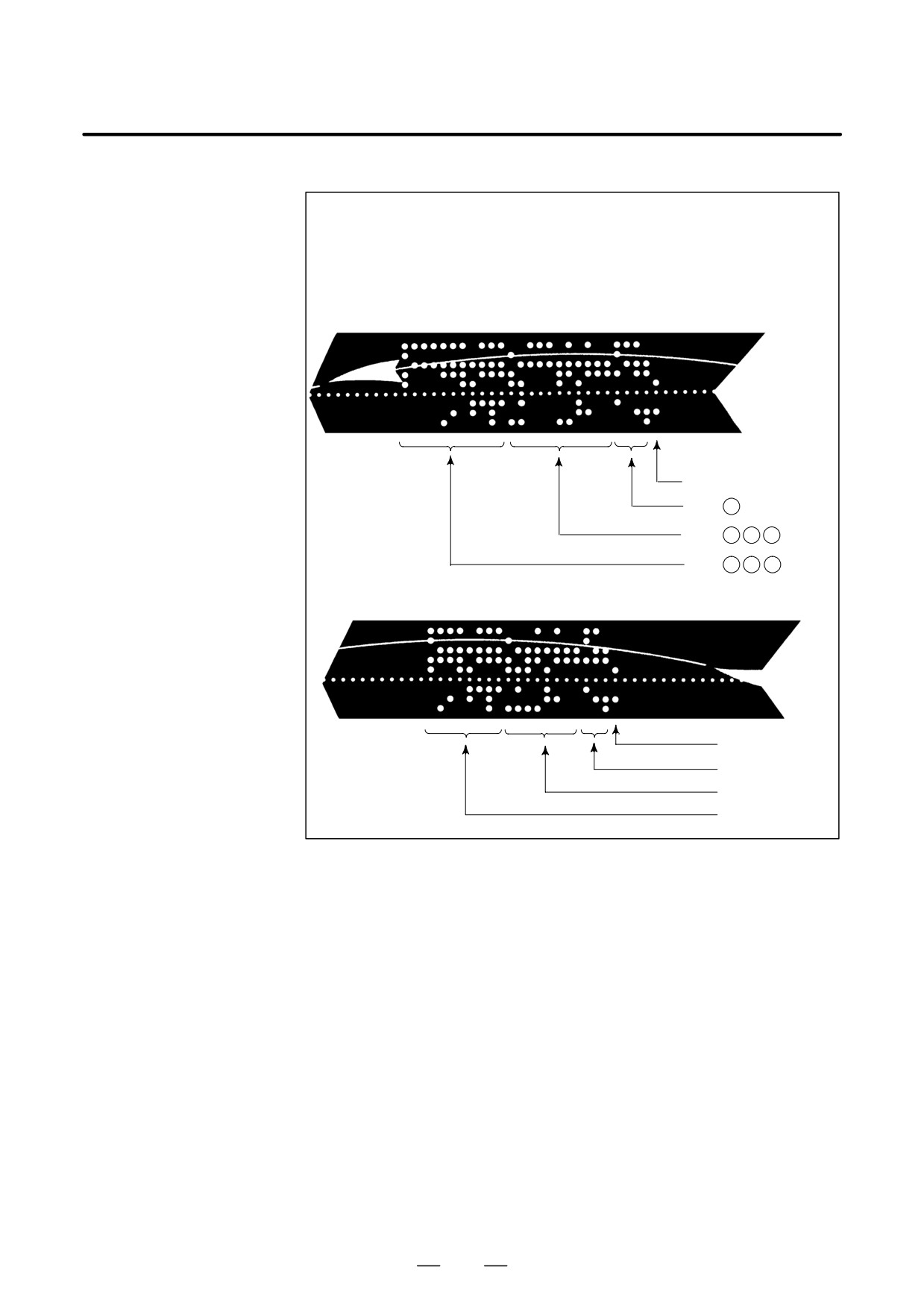
D Data output command
DPRNT
DPRNT [ a #b
[ c d ]
… ]
Number of significant decimal places
Number of significant digits in the integer part
Variable
Character
The DPRNT command outputs characters and each digit in the value of
a variable according to the code set in the settings (ISO).
(i) For an explanation of the DPRNT command, see Items (i), (iii), and
(iv) for the BPRNT command.
(ii) When outputting a variable, specify # followed by the variable
number, then specify the number of digits in the integer part and the
number of decimal places enclosed in brackets.
One code is output for each of the specified number of digits, starting
with the highest digit. For each digit, a code is output according to
the settings (ISO). The decimal point is also output using a code set
in the settings (ISO).
Each variable must be a numeric value consisting of up to eight
digits. When high-order digits are zeros, these zeros are not output
if PRT (bit1 of parameter 6001) is 1. If parameter PRT is 0, a space
code is output each time a zero is encountered.
When the number of decimal places is not zero, digits in the decimal
part are always output. If the number of decimal places is zero, no
decimal point is output.
When PRT (bit 1 of parameter 6001) is 0, a space code is output to
indicate a positive number instead of +; if parameter PRT is 1, no
code is output.
349
15. CUSTOM MACRO
PROGRAMMING
B-64124EN/01
Example )
DPRNT [ X#2 [53] Y#5 [53] T#30 [20] ]
Variable value
#2=128.47398
#5=-91.2
#30=123.456
(1) Parameter PRT(No.6001#1)=0
L F
T
sp
23
Y -
sp
sp sp
91200
X
sp sp sp
128474
(2) Parameter PRT(No.6001#1)=0
LF
T23
Y-91.200
X128.474
D Close command PCLOS
PCLOS ;
The PCLOS command releases a connection to an external input/output
device. Specify this command when all data output commands have
terminated. DC4 control code is output from the CNC.
D Required setting
Specify the channel use for setting data (I/O channel). According to the
specification of this data, set data items (such as the baud rate) for the
reader/punch interface.
I/O channel 0 : Parameters (No.101, No.102 and No.103)
I/O channel 1 : Parameters (No.111, No.112 and No.113)
I/O channel 2 : Parameters (No.112, No.122 and No.123)
Never specify the output device FANUC Cassette or Floppy for punching.
When specifying a DPRNT command to output data, specify whether
leading zeros are output as spaces (by setting PRT (bit 1 of parameter
6001) to 1 or 0).
To indicate the end of a line of data in ISO code, specify whether to use
only an LF (CRO, of bit 4 of parameter 6001 is 0) or an LF and CR (CRO
of bit 4 of parameter 6001 is 1).
350

B-64124EN/01
PROGRAMMING
15. CUSTOM MACRO
NOTE
1
It is not necessary to always specify the open command
(POPEN), data output command (BPRNT, DPRNT), and
close command
(PCLOS) together. Once an open
command is specified at the beginning of a program, it does
not need to be specified again except after a close
command was specified.
2
Be sure to specify open commands and close commands
in pairs. Specify the close command at the end of the
program. However, do not specify a close command if no
open command has been specified.
3
When a reset operation is performed while commands are
being output by a data output command, output is stopped
and subsequent data is erased. Therefore, when a reset
operation is performed by a code such as M30 at the end
of a program that performs data output, specify a close
command at the end of the program so that processing such
as M30 is not performed until all data is output.
4
Abbreviated macro words enclosed in brackets [ ] remains
unchanged. However, note that when the characters in
brackets are divided and input several times, the second
and subsequent abbreviations are converted and input.
5
O can be specified in brackets [ ]. Note that when the
characters in brackets [ ] are divided and input several
times, O is omitted in the second and subsequent inputs.
351
15. CUSTOM MACRO
PROGRAMMING
B-64124EN/01
When a program is being executed, another program can be called by
15.11
inputting an interrupt signal (UINT) from the machine. This function is
INTERRUPTION TYPE
referred to as an interruption type custom macro function. Program an
CUSTOM MACRO
interrupt command in the following format:
Format
M96 Pffff ; Enables custom macro interrupt
M97 ;
Disables custom macro interrupt
Explanations
Use of the interruption type custom macro function allows the user to call
a program during execution of an arbitrary block of another program.
This allows programs to be operated to match situations which vary from
time to time.
(1) When a tool abnormality is detected, processing to handle the
abnormality is started by an external signal.
(2) A sequence of machining operations is interrupted by another
machining operation without the cancellation of the current operation.
(3) At regular intervals, information on current machining is read.
Listed above are examples like adaptive control applications of the
interruption type custom macro function.
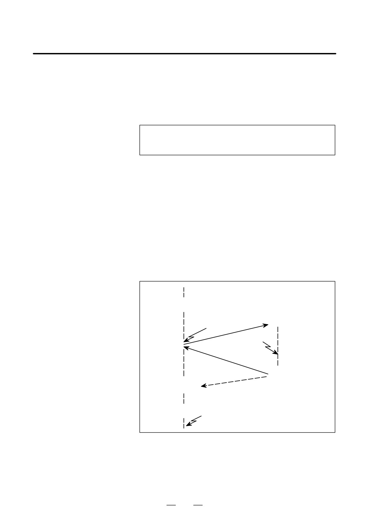
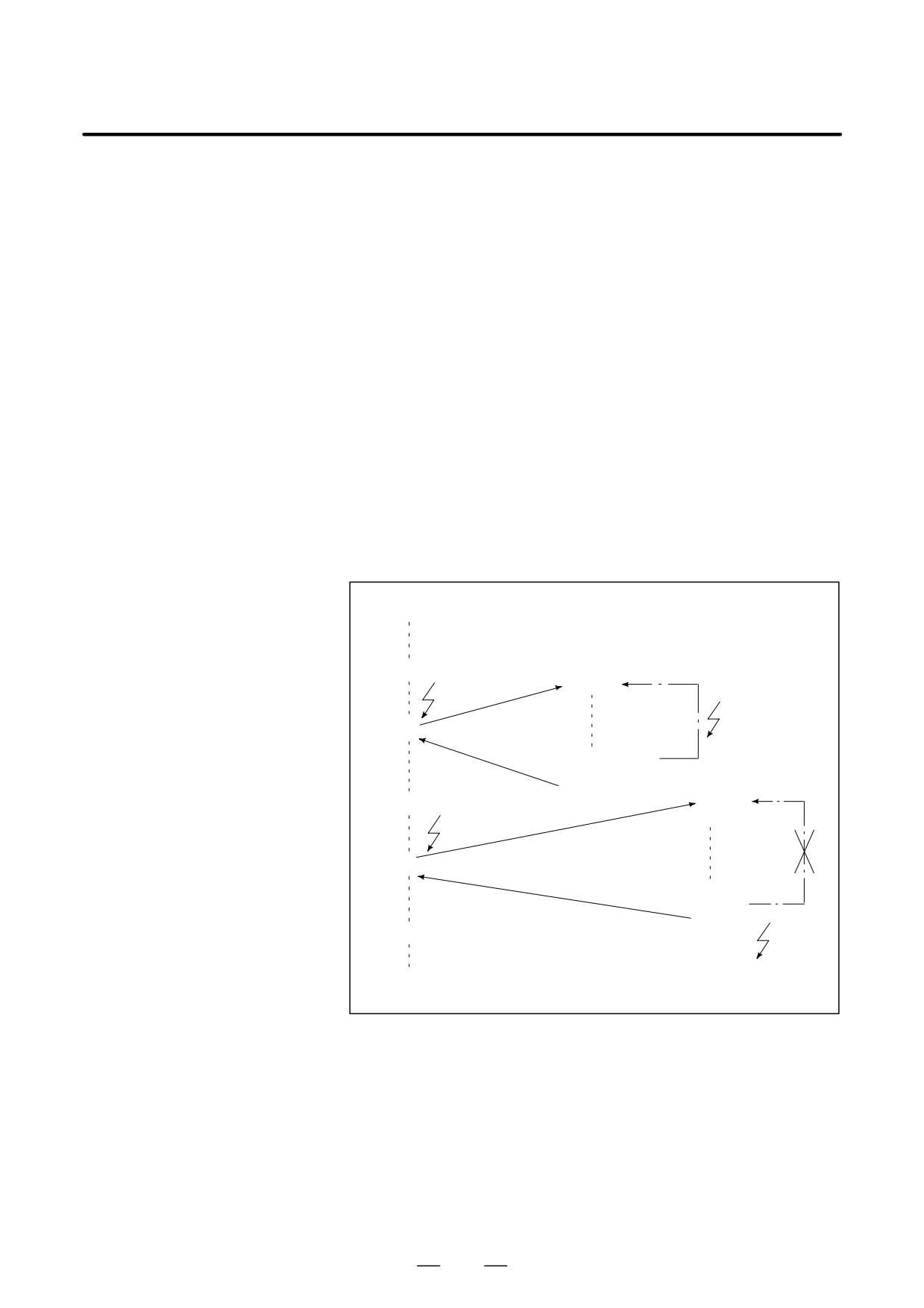
M96
Pxxxx;
Interrupt
signal
O xxxx;
(UINT)
Interrupt
signal
(UINT)**
M99 (Pffff);
Nffff;
M97 ;
Interrupt
signal
(UINT)*
Fig. 15.11 Interruption type custom macro function
When M96Pxxxx is specified in a program, subsequent program
operation can be interrupted by an interrupt signal (UINT) input to
execute the program specified by Pxxxx.
352
B-64124EN/01
PROGRAMMING
15. CUSTOM MACRO
CAUTION
When the interrupt signal (UINT, marked by * in Fig. 15.11)
is input after M97 is specified, it is ignored. And the interrupt
signal must not be input during execution of the interrupt
program.
15.11.1
Specification Method
Explanations
D Interrupt conditions
A custom macro interrupt is available only during program execution. It
is enabled under the following conditions
- When memory operation or MDI operation is selected
- When STL (start lamp) is on
- When a custom macro interrupt is not currently being processed
D Specification
Generally, the custom macro interrupt function is used by specifying M96
to enable the interrupt signal (UINT) and M97 to disable the signal.
Once M96 is specified, a custom macro interrupt can be initiated by the
input of the interrupt signal (UINT) until M97 is specified or the NC is
reset. After M97 is specified or the NC is reset, no custom macro
interrupts are initiated even when the interrupt signal (UINT) is input.
The interrupt signal (UINT) is ignored until another M96 command is
specified.
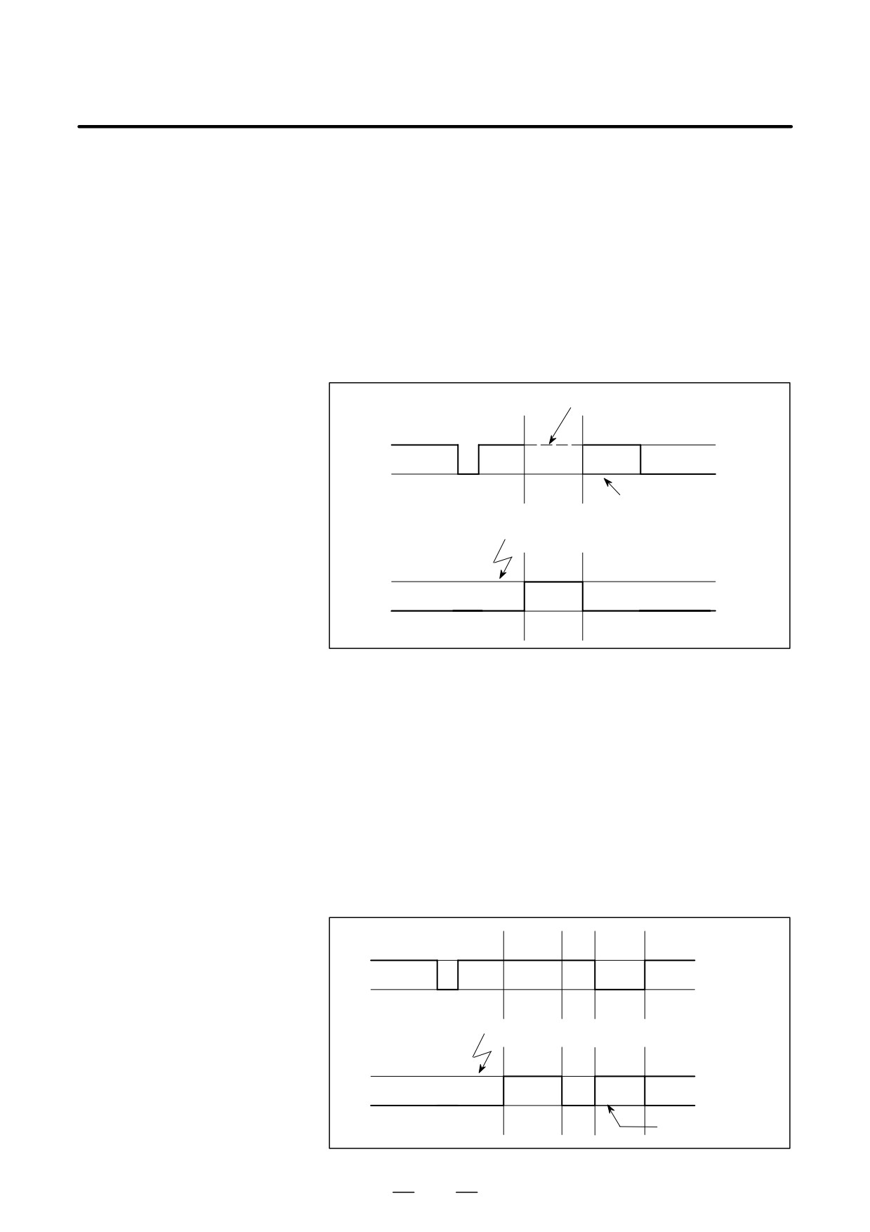
M96
M97
M96
1
0
Interrupt signal
(UINT)
Effective interrupt
input signal
When UINT is kept on
The interrupt signal (UINT) becomes valid after M96 is specified. Even
when the signal is input in M97 mode, it is ignored. When the signal input
in M97 mode is kept on until M96 is specified, a custom macro interrupt
is initiated as soon as M96 is specified (only when the status-triggered
scheme is employed); when the edge-triggered scheme is employed, the
custom macro interrupt is not initiated even when M96 is specified.
353

15. CUSTOM MACRO
PROGRAMMING
B-64124EN/01
NOTE
For the status-triggered and edge-triggered schemes, see
Item “Custom macro interrupt signal (UINT)” of II- 15.11.2.
15.11.2
Details of Functions
Explanations
D Subprogram-type
There are two types of custom macro interrupts: Subprogram-type
interrupt and macro-type
interrupts and macro-type interrupts. The interrupt type used is selected
interrupt
by MSB (bit 5 of parameter 6003).
(a) Subprogram-type interrupt
An interrupt program is called as a subprogram. This means that the
levels of local variables remain unchanged before and after the interrupt.
This interrupt is not included in the nesting level of subprogram calls.
(b) Macro-type interrupt
An interrupt program is called as a custom macro. This means that the
levels of local variables change before and after the interrupt. The
interrupt is not included in the nesting level of custom macro calls. When
a subprogram call or a custom macro call is performed within the interrupt
program, this call is included in the nesting level of subprogram calls or
custom macro calls. Arguments cannot be passed from the current
program even when the custom macro interrupt is a macro-type interrupt.
D M codes for custom
In general, custom macro interrupts are controlled by M96 and M97.
macro interrupt control
However, these M codes, may already being used for other purposes (such
as an M function or macro M code call) by some machine tool builders.
For this reason, MPR (bit 4 of parameter 6003) is provided to set M codes
for custom macro interrupt control.
When specifying this parameter to use the custom macro interrupt control
M codes set by parameters, set parameters 6033 and 6034 as follows:
Set the M code to enable custom macro interrupts in parameter 6033, and
set the M code to disable custom macro interrupts in parameter 6034.
When specifying that parameter-set M codes are not used, M96 and M97
are used as the custom macro control M codes regardless of the settings
of parameters 6033 and 6034.
The M codes used for custom macro interrupt control are processed
internally (they are not output to external units). However, in terms of
program compatibility, it is undesirable to use M codes other than M96
and M97 to control custom macro interrupts.
D Custom macro interrupts
When performing a custom macro interrupt, the user may want to
and NC statements
interrupt the NC statement being executed, or the user may not want to
perform the interrupt until the execution of the current block is completed.
MIN (bit 2 of parameter 6003)is used to select whether to perform
interrupts even in the middle of a block or to wait until the end of the
block.
354
B-64124EN/01
PROGRAMMING
15. CUSTOM MACRO
Type I
(i)
When the interrupt signal (UINT) is input, any movement or dwell
(when an interrupt is
being performed is stopped immediately and the interrupt program
performed even in the
is executed.
middle of a block)
(ii)
If there are NC statements in the interrupt program, the command in
the interrupted block is lost and the NC statement in the interrupt
program is executed. When control is returned to the interrupted
program, the program is restarted from the next block after the
interrupted block.
(iii)
If there are no NC statements in the interrupt program, control is
returned to the interrupted program by M99, then the program is
restarted from the command in the interrupted block.
Interrupted by macro interrupt
Execution in
progress
ÉÉÉÉ
ÉÉÉÉ
Normal program
ÉÉÉÉ
CNC command restart;
when there are no NC state-
Interrupt signal (UINT) input
ments in the interrupt pro-
gram
Execution in
progress
Custom macro
interrupt
Type II
(i)
If the block being executed is not a block that consists of several cycle
(when an interrupt is
operations such as a drilling canned cycle and automatic reference
performed at the end of
position return (G28), an interrupt is performed as follows:
the block)
When an interrupt signal (UINT) is input, macro statements in the
interrupt program are executed immediately unless an NC statement
is encountered in the interrupt program. NC statements are not
executed until the current block is completed.
(ii)
If the block being executed consists of several cycle operations, an
interrupt is performed as follows:
When the last movement in the cycle operations is started, macro
statements in the interrupt program are executed unless an NC
statement is encountered. NC statements are executed after all cycle
operations are completed.
Execution in
progress
Normal program
Interrupt signal (UINT) input
Execution in
progress
ÉÉÉ
ÉÉÉ
Custom macro
ÉÉÉ
NC statement in the
interrupt
interrupt program
355
15. CUSTOM MACRO
PROGRAMMING
B-64124EN/01
D Conditions for enabling
The interrupt signal becomes valid after execution starts of a block that
and disabling the custom
contains M96 for enabling custom macro interrupts. The signal becomes
macro interrupt signal
invalid when execution starts of a block that contains M97.
While an interrupt program is being executed, the interrupt signal
becomes invalid. The signal become valid when the execution of the
block that immediately follows the interrupted block in the main program
is started after control returns from the interrupt program. In type I, if the
interrupt program consists of only macro statements, the interrupt signal
becomes valid when execution of the interrupted block is started after
control returns from the interrupt program.
D Custom macro interrupt
during execution of a
block that involves cycle
operation
For type I
Even when cycle operation is in progress, movement is interrupted, and
the interrupt program is executed. If the interrupt program contains no
NC statements, the cycle operation is restarted after control is returned to
the interrupted program. If there are NC statements, the remaining
operations in the interrupted cycle are discarded, and the next block is
executed.
For type II
When the last movement of the cycle operation is started, macro
statements in the interrupt program are executed unless an NC statement
is encountered. NC statements are executed after cycle operation is
completed.
356
B-64124EN/01
PROGRAMMING
15. CUSTOM MACRO
D Custom macro interrupt
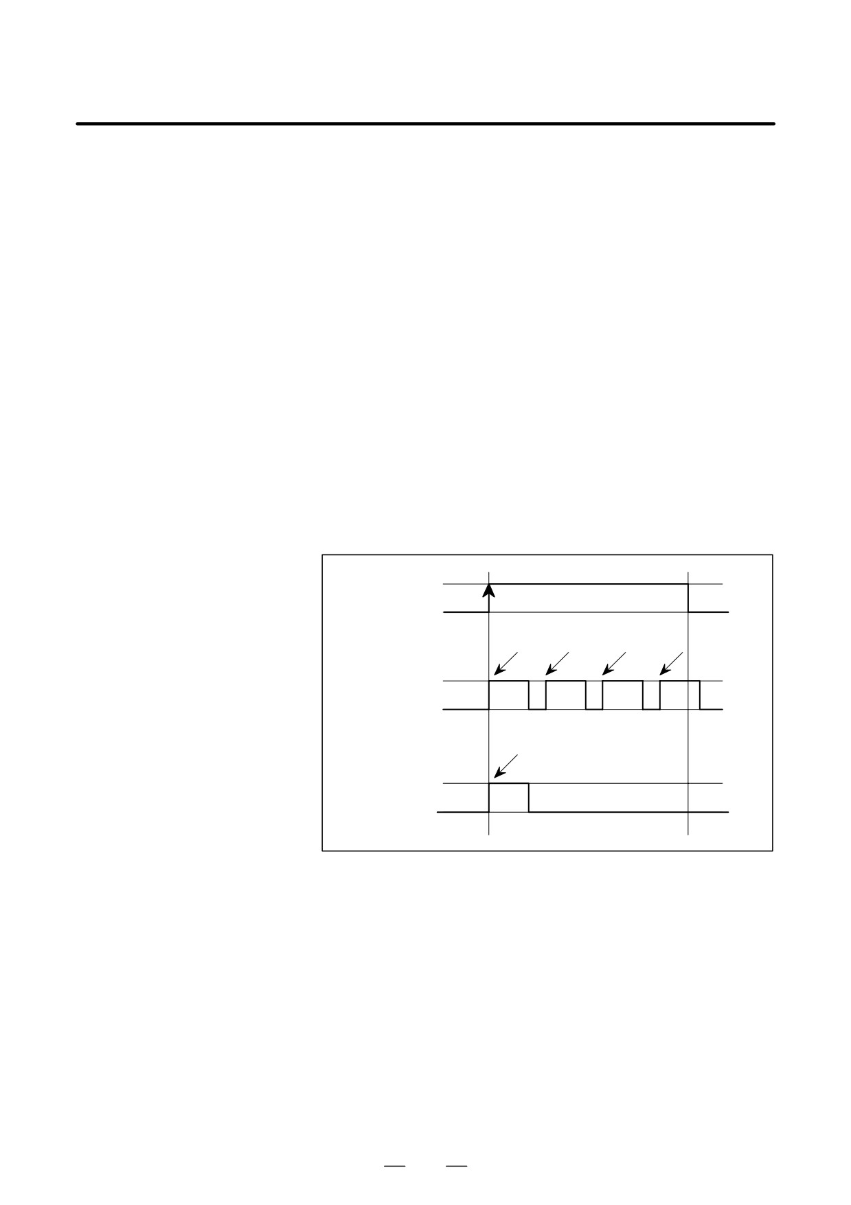
There are two schemes for custom macro interrupt signal (UINT) input:
signal (UINT)
The status-triggered scheme and edge- triggered scheme. When the
status-triggered scheme is used, the signal is valid when it is on. When
the edge triggered scheme is used, the signal becomes valid on the rising
edge when it switches from off to on status.
One of the two schemes is selected with TSE (bit 3 of parameter 6003).
When the status-triggered scheme is selected by this parameter, a custom
macro interrupt is generated if the interrupt signal (UINT) is on at the time
the signal becomes valid. By keeping the interrupt signal (UINT) on, the
interrupt program can be executed repeatedly.
When the edge-triggered scheme is selected, the interrupt signal (UINT)
becomes valid only on its rising edge. Therefore, the interrupt program
is executed only momentarily (in cases when the program consists of only
macro statements). When the status-triggered scheme is inappropriate,
or when a custom macro interrupt is to be performed just once for the
entire program (in this case, the interrupt signal may be kept on), the
edge-triggered scheme is useful.
Except for the specific applications mentioned above, use of either
scheme results in the same effects. The time from signal input until a
custom macro interrupt is executed does not vary between the two
schemes.
1
0
Interrupt signal (UINT)
Interrupt Interrupt Interrupt
Interrupt
execution execution execution
execution
Status-triggered
scheme
Interrupt
execution
Edge-triggered
scheme
In the above example, an interrupt is executed four times when the status
triggered scheme is used; when the edge- triggered scheme is used, the
interrupt is executed just once.
357
15. CUSTOM MACRO
PROGRAMMING
B-64124EN/01
D Return from a custom
To return control from a custom macro interrupt to the interrupted
macro interrupt
program, specify M99. A sequence number in the interrupted program
can also be specified using address P. If this is specified, the program is
searched from the beginning for the specified sequence number. Control
is returned to the first sequence number found.
When a custom macro interrupt program is being executed, no interrupts
are generated. To enable another interrupt, execute M99. When M99 is
specified alone, it is executed before the preceding commands terminate.
Therefore, a custom macro interrupt is enabled for the last command of
the interrupt program. If this is inconvenient, custom macro interrupts
should be controlled by specifying M96 and M97 in the program.
When a custom macro interrupt is being executed, no other custom macro
interrupts are generated; when an interrupt is generated, additional
interrupts are inhibited automatically. Executing M99 makes it possible
for another custom macro interrupt to occur. M99 specified alone in a
block is executed before the previous block terminates. In the following
example, an interrupt is enabled for the Gxx block of O1234. When the
signal is input, O1234 is executed again. O5678 is controlled by M96 and
M97. In this case, an interrupt is not enabled for O5678 (enabled after
control is returned to O1000).
O1000;
M96P1234;
Interrupt
O1234
Interrupt
GxxXxxx;
M99;
M96P5678
O5678
M97
Interrupt
GxxXxxx;
M96;
Interrupt
M99;
M97
358

B-64124EN/01
PROGRAMMING
15. CUSTOM MACRO
NOTE
When an M99 block consists only of address O, N, P, L, or
M, this block is regarded as belonging to the previous block
in the program. Therefore, a single-block stop does not
occur for this block. In terms of programming, the following
and
are basically the same.
(The difference is
whether Gff is executed before M99 is recognized.)
Gff Xfff ;
M99 ;
Gff Xfff M99 ;
D Custom macro interrupt
A custom macro interrupt is different from a normal program call. It is
and modal information
initiated by an interrupt signal (UINT) during program execution. In
general, any modifications of modal information made by the interrupt
program should not affect the interrupted program.
For this reason, even when modal information is modified by the interrupt
program, the modal information before the interrupt is restored when
control is returned to the interrupted program by M99.
When control is returned from the interrupt program to the interrupted
program by M99 Pxxxx, modal information can again be controlled by
the program. In this case, the new continuous information modified by
the interrupt program is passed to the interrupted program. Restoration of
the old modal information present before the interrupt is not desirable.
This is because after control is returned, some programs may operate
differently depending on the modal information present before the
interrupt. In this case, the following measures are applicable:
(1) The interrupt program provides modal information to be used after
control is returned to the interrupted program.
359
15. CUSTOM MACRO
PROGRAMMING
B-64124EN/01
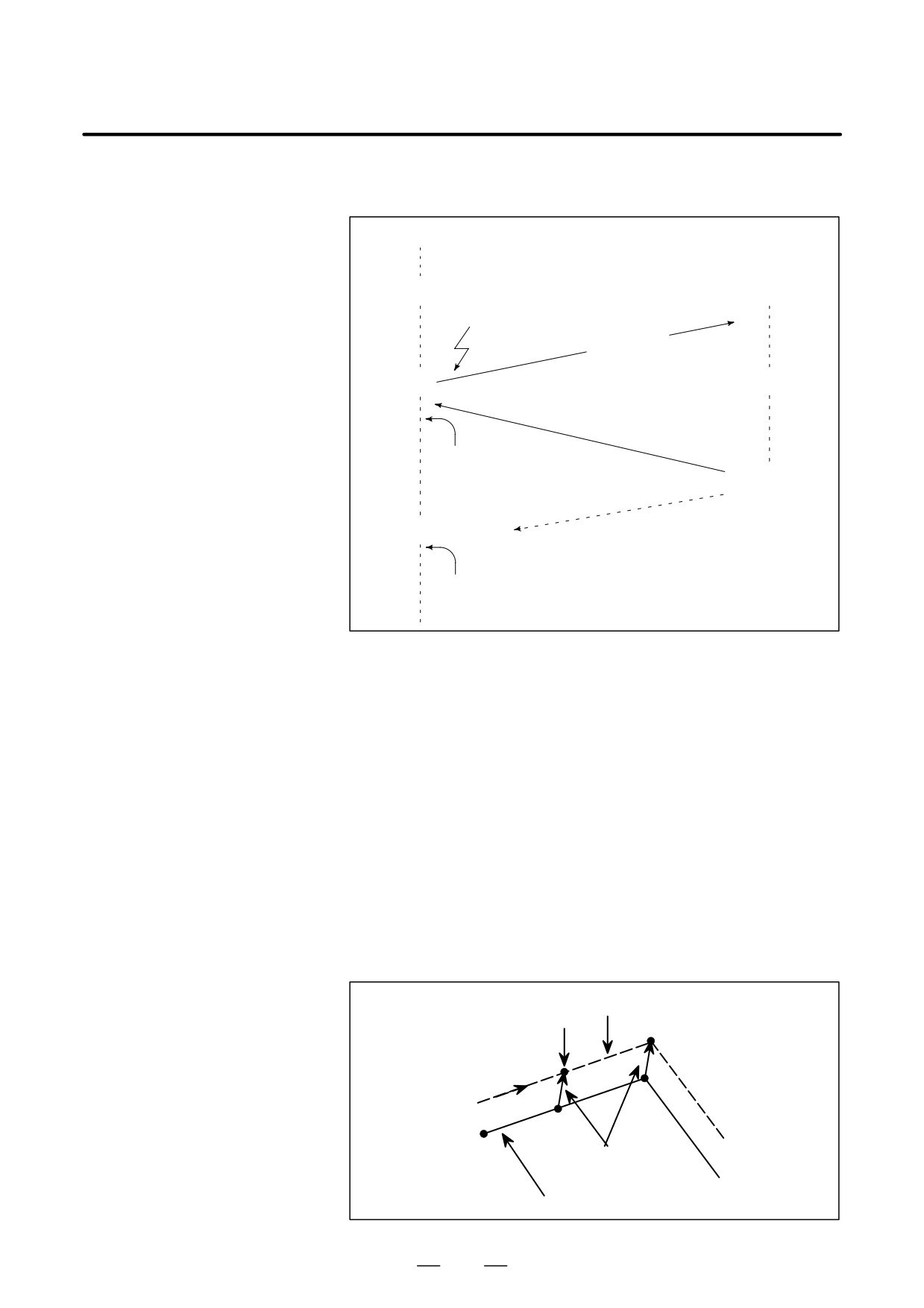
(2) After control is returned to the interrupted program, modal
information is specified again as necessary.
O∆∆∆∆
M96Pxxx
Oxxx;
Interrupt signal (UINT)
Modify modal
information
(Without P specification)
Modal
information remains
M99(Pffff);
unchanged before and
after the interrupt.
Nffff;
(With P specification)
The new modal information modified by the interrupt program
is present.
Modal information when
The modal information present before the interrupt becomes valid. The
control is returned by
new modal information modified by the interrupt program is made
M99
invalid.
Modal information when
The new modal information modified by the interrupt program remains
control is returned by
valid even after control is returned. The old modal information which was
M99 Pffff
valid in the interrupted block can be read using custom macro system
variables #4001 to #4120.
Note that when modal information is modified by the interrupt program,
system variables #4001 to #4120 are not changed.
D System variables
S The coordinates of point A can be read using system variables #5001
(position information
and up until the first NC statement is encountered.
values) for the interrupt
S The coordinates of point A’ can be read after an NC statement with no
program
move specifications appears.
S The machine coordinates and workpiece coordinates of point B’ can
be read using system variables #5021 and up and #5041 and up.
Tool center path
Interrupt generated
B
B’
A
A’
Offset vector
Programmed tool path
360
B-64124EN/01
PROGRAMMING
15. CUSTOM MACRO
D Custom macro interrupt
When the interrupt signal (UINT) is input and an interrupt program is
and custom macro
called, the custom macro modal call is canceled (G67). However, when
modal call
G66 is specified in the interrupt program, the custom macro modal call
becomes valid. When control is returned from the interrupt program by
M99, the modal call is restored to the state it was in before the interrupt
was generated. When control is returned by M99Pxxxx;, the modal call
in the interrupt program remains valid.
D Custom macro interrupt
When the interrupt signal (UINT) is input while a return operation is being
and program restart
performed in the dry run mode after the search operation for program
restart, the interrupt program is called after restart operation terminates
for all axes. This means that interrupt type II is used regardless of the
parameter setting.
D DNC operation and
“Interruption type custom macro” cannot be done during DNC operation
Interruption type custom
or executing a program with an external input-output device.
macro
361
16. PATTERN DATA INPUT
FUNCTION
PROGRAMMING
B-64124EN/01
PATTERN DATA INPUT FUNCTION
16
This function enables users to perform programming simply by extracting
numeric data (pattern data) from a drawing and specifying the numerical
values from the MDI panel.
This eliminates the need for programming using an existing NC language.
With the aid of this function, a machine tool builder can prepare the
program of a hole machining cycle (such as a boring cycle or tapping
cycle) using the custom macro function, and can store it into the program
memory.
This cycle is assigned pattern names, such as BOR1, TAP3, and DRL2.
An operator can select a pattern from the menu of pattern names displayed
on the screen.
Data (pattern data) which is to be specified by the operator should be
created in advance with variables in a drilling cycle.
The operator can identify these variables using names such as DEPTH,
RETURN RELIEF, FEED, MATERIAL or other pattern data names. The
operator assigns values (pattern data) to these names.
362
16. PATTERN DATA INPUT
B-64124EN/01
PROGRAMMING
FUNCTION
16.1
OFFSET
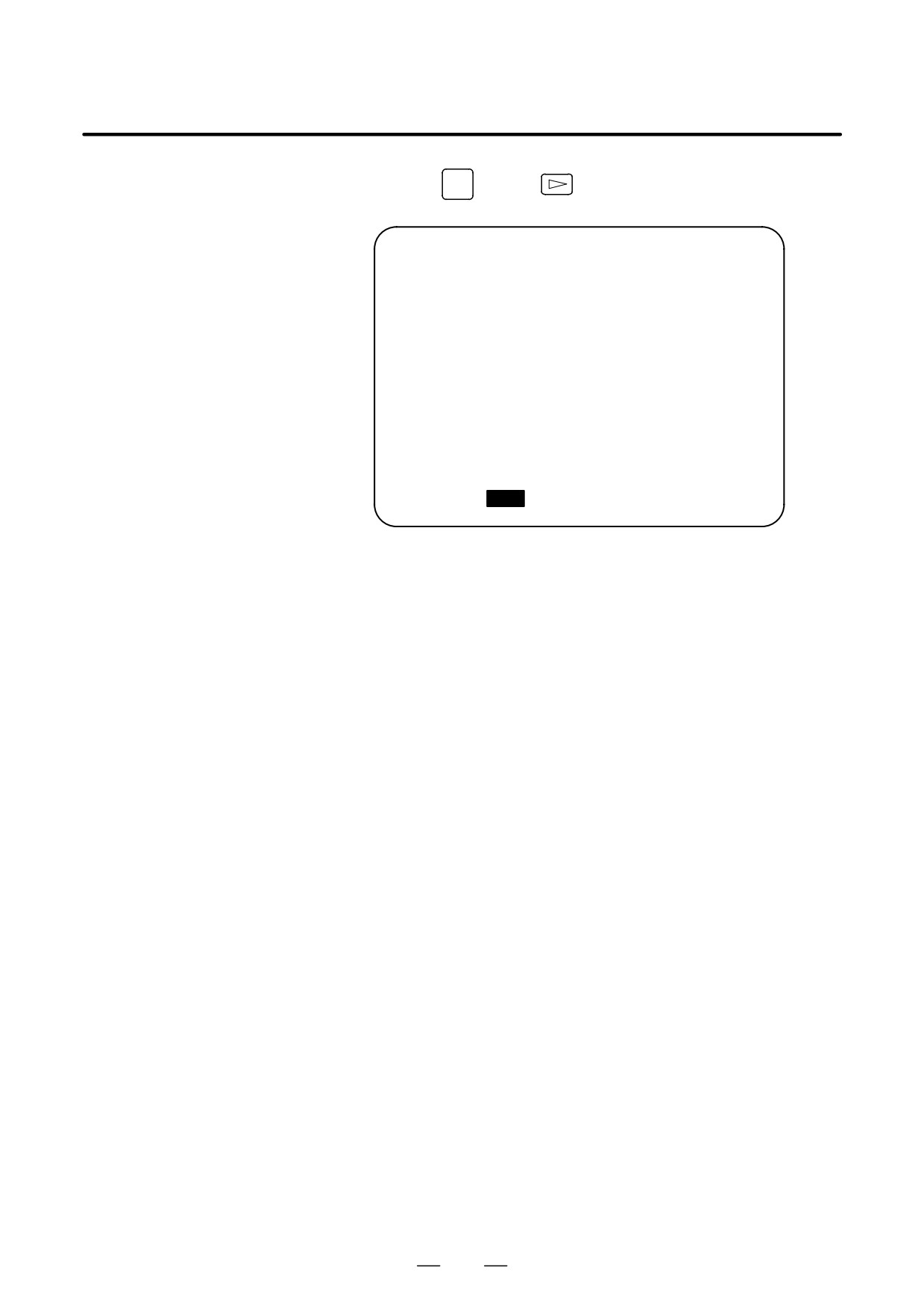
Pressing the
SETTING
key and
[MENU] is displayed on the following
DISPLAYING THE
pattern menu screen.
PATTERN MENU
MENU : HOLE PATTERN
O0000 N00000
1. BOLT HOLE
2. GRID
3. LINE ANGLE
4. TAPPING
5. DRILLING
6. BORING
7. POCKET
8. PECK
9. TEST PATRN
10. BACK
> _
MDI **** *** ***
16:05:59
[ MACRO ] [
MENU
] [ OPR
] [
] [(OPRT)]
HOLE PATTERN : This is the menu title. An arbitrary character string
consisting of up to 12 characters can be specified.
BOLT HOLE
:
This is the pattern name. An arbitrary character
string consisting of up to 10 characters can be
specified, including katakana.
The machine tool builder should specify the character strings for the menu
title and pattern name using the custom macro, and load the character
strings into program memory as a subprogram of program No. 9500.
363

16. PATTERN DATA INPUT
FUNCTION
PROGRAMMING
B-64124EN/01
D Macro commands
Menu title : C1 C2 C3 C4 C5 C6 C7 C8 C9C10 C11 C12
specifying the menu
C1,C2,,C12 : Characters in the menu title (12 characters)
title
Macro instruction
G65 H90 Pp Qq Rr Ii Jj Kk :
H90:Specifies the menu title
p : Assume a1 and a2 to be the codes of characters C1 and C2. Then,
Pfff
fff
Code a2 of character C2
Code a1 of character C1
q : Assume a3 and a4 to be the codes of characters C3 and C4. Then,
q=a3 103+a4
r : Assume a5 and a6 to be the codes of characters C5 and C6. Then,
r=a5 103+a6
i : Assume a7 and a8 to be the codes of characters C7 and C8. Then,
i=a7 103+a8
j : Assume a9 and a10 to be the codes of characters C9 and C10. Then,
j=a9 103+a10
k : Assume a11 and a12 to be the codes of characters C11 and C12.Then,
k=a11 103+a12
Example) If the title of the menu is HOLE PATTERN” then the macro
instruction is as follows:
G65 H90 P072079 Q076069 R032080
HO LE
P
I065084 J084069 K082078;
AT
TE
RN
For codes corresponding to these characters, refer to the Table
16.3 (a) in II-16.3.
364

16. PATTERN DATA INPUT
B-64124EN/01
PROGRAMMING
FUNCTION
D Macro instruction
Pattern name: C1 C2 C3 C4 C5 C6 C7 C8 C9C10
describing the pattern
C1, C2, ,C10: Characters in the pattern name (10 characters)
name
Macro instruction
G65 H91 Pn Qq Rr Ii Jj Kk ;
H91: Specifies the menu title
n : Specifies the menu No. of the pattern name
n=1 to 10
q : Assume a1 and a2 to be the codes of characters C1 and C2. Then,
q=a1 103+a2
r : Assume a3 and a4 to be the codes of characters C3 and C4. Then,
r=a3 103+a4
i : Assume a5 and a6 to be the codes of characters C5 and C6. Then,
i=a5 103+a6
j : Assume a7 and a8 to be the codes of characters C7 and C8. Then,
j=a7 103+a8
k : Assume a9 and a10 to be the codes of characters C9 and C10. Then,
k=a9 103+a10
Example) If the pattern name of menu No. 1 is BOLT HOLE ” then the
macro instruction is as follows.
G65 H91 P1 Q066079 R076084 I032072 J079076 K069032 ;
BO
LT
H OL
E
For codes corresponding to these characters, refer to the Table 16.3
(a) in II-16.3.
D Pattern No. selection
To select a pattern from the pattern menu screen, enter the corresponding
pattern No. The following is an example.
1
INPUT
The selected pattern No. is assigned to system variable #5900. The
custom macro of the selected pattern can be started by starting a fixed
program (external program No. search) with an external signal then
referring to the system variable #5900 in the program.
NOTE
If each characters of P, Q, R, I, J, and K are not specified in
a macro instruction, two spaces are assigned to each
omitted character.
365
16. PATTERN DATA INPUT
FUNCTION
PROGRAMMING
B-64124EN/01
Example
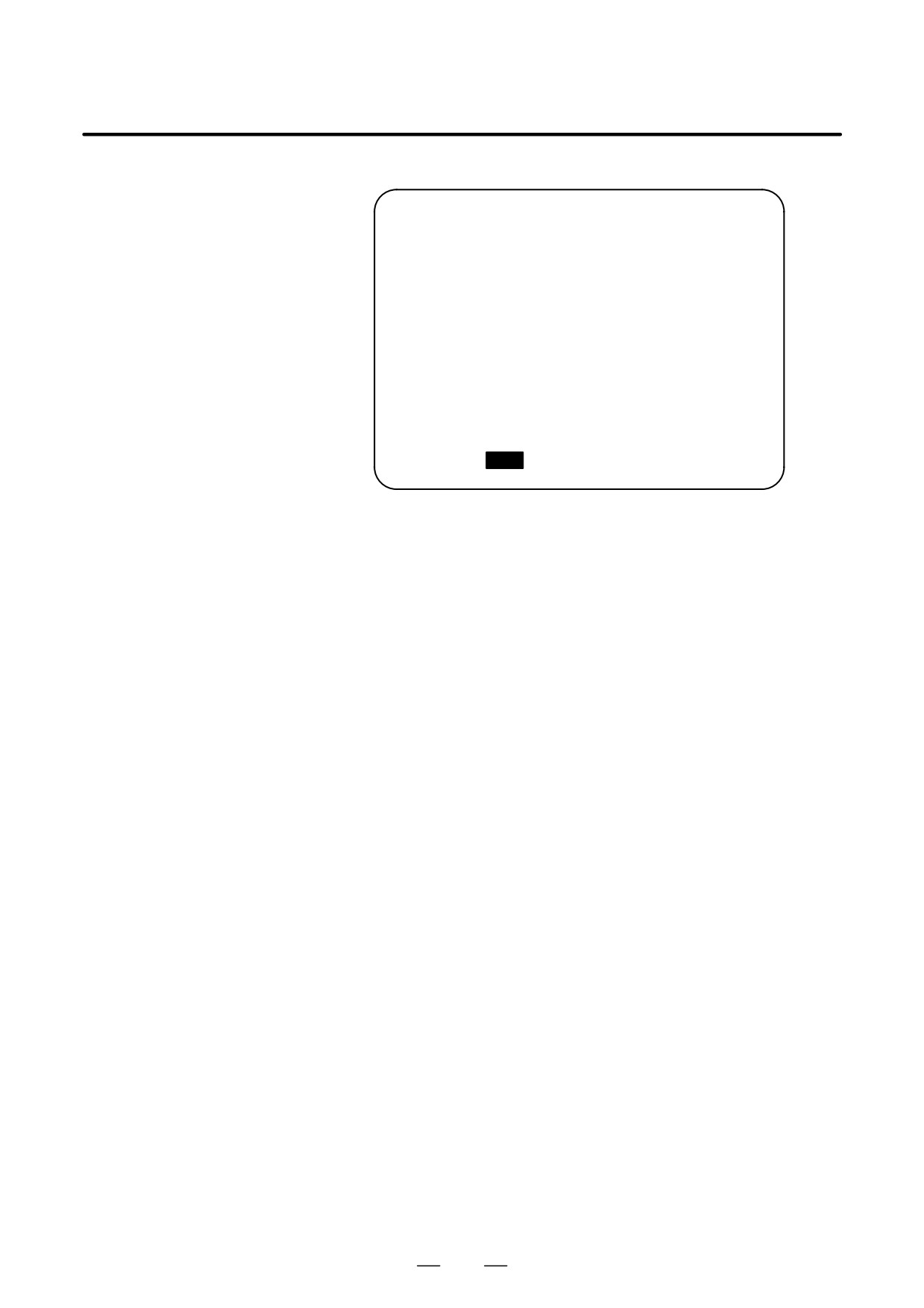
Custom macros for the menu title and hole pattern names.
MENU : HOLE PATTERN
O0000 N00000
1. BOLT HOLE
2. GRID
3. LINE ANGLE
4. TAPPING
5. DRILLING
6. BORING
7. POCKET
8. PECK
9. TEST PATRN
10. BACK
> _
MDI **** *** ***
16:05:59
[ MACRO ] [
MENU ] [ OPR ] [
] [ (OPRT) ]
O9500 ;
N1 G65 H90 P072079 Q076069 R032080 I065084 J084069 K082078 ;
HOLE PATTERN
N2 G65 H91 P1 Q066079 R076084 I032072 J079076 K069032 ;
1.BOLT HOLE
N3 G65 H91 P2 Q071082 R073068 ;
2.GRID
N4 G65 H91 P3 Q076073 R078069 I032065 J078071 K076069 ;
3.LINE ANGLE
N5 G65 H91 P4 Q084065 R080080 I073078 J071032 ;
4.TAPPING
N6 G65 H91 P5 Q068082 R073076 I076073 J078071 ;
5.DRILLING
N7 G65 H91 P6 Q066079 R082073 I078071 ;
6.BORING
N8 G65 H91 P7 Q080079 R067075 I069084 ;
7.POCKET
N9 G65 H91 P8 Q080069 R067075 ;
8.PECK
N10 G65 H91 P9 Q084069 R083084 I032080 J065084 K082078 ;
9.TEST PATRN
N11 G65 H91 P10 Q066065 R0670750 ;
10.BACK
N12 M99 ;
366
16. PATTERN DATA INPUT
B-64124EN/01
PROGRAMMING
FUNCTION
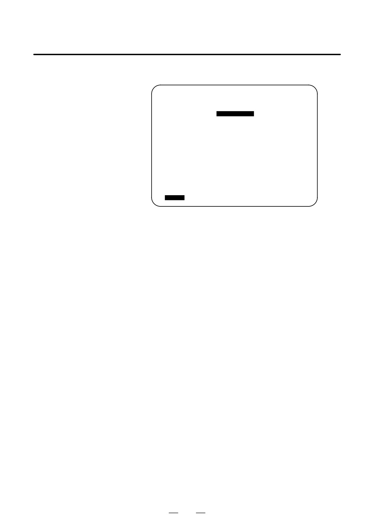
When a pattern menu is selected, the necessary pattern data is
16.2
displayed.
PATTERN DATA
DISPLAY
VAR. : BOLT HOLE
O0001 N00000
NO. NAME
DATA
COMMENT
500 TOOL
0.000
501 STANDARD X
0.000
*BOLT HOLE
502 STANDARD Y
0.000
CIRCLE*
503 RADIUS
0.000
SET PATTERN
504 S. ANGL
0.000
DATA TO VAR.
505 HOLES NO
0.000
NO.500-505.
506
0.000
507
0.000
ACTUAL POSITION (RELATIVE)
X
0.000
Y
0.000
Z
0.000
> _
MDI **** *** ***
16:05:59
[ MACRO ] [ MENU ] [ OPR
] [
] [(OPRT)]
BOLT HOLE
: This is the pattern data title. A character string
consisting of up to 12 characters can be set.
TOOL :
This is the variable name. A character string
consisting of up to 10 characters can be set.
*BOLT HOLE CIRCLE* :
This is a comment statement. A character string
can be displayed consisting of up to 8 lines, 12
characters per line.
(It is permissible to use katakana in a character string or line.)
The machine tool builder should program the character strings of pattern
data title, pattern name, and variable name using the custom macro, and
load them into the program memory as a subprogram whose No. is 9500
plus the pattern No. (O9501 to O9510).
367
16. PATTERN DATA INPUT
FUNCTION
PROGRAMMING
B-64124EN/01
Macro instruction
Menu title : C1 C2 C3 C4 C5 C6 C7 C8 C9C10C11C12
specifying the pattern
C1 ,C2,…, C12 : Characters in the menu title (12 characters)
data title
Macro instruction
G65 H92 Pp Qq Rr Ii Jj Kk ;
(the menu title)
H92 : Specifies the pattern name
p : Assume a1 and a2 to be the codes of characters C1 and C2. Then,
p=a1 103+a2
q : Assume a3 and a4 to be the codes of characters C3 and C4. Then,
q=a3 103+a4
r : Assume a5 and a6 to be the codes of characters C5 and C6. Then,
r=a5 103+a6
i : Assume a7 and a8 to be the codes of characters C7 and C8. Then,
i=a7 103+a8
j : Assume a9 and a10 to be the codes of characters C9 and C10. Then,
j=a9 103+a10
k : Assume a11 and a12 to be the codes of characters C11 and C12. Then,
k=a11 103+a12
Example) Assume that the pattern data title is BOLT HOLE .” The
macro instruction is given as follows:
G65 H92 P066079 Q076084 R032072 I079076 J069032;
BO
LT
H OL
E
For codes corresponding to these characters, refer to the
Table 16.3 (a) in II-16.3.
D Macro instruction
Variable name : C1 C2 C3 C4 C5 C6 C7 C8 C9C10
specifying the variable
C1, C2,…, C10 : Characters in the variable name (10 characters)
name
Macro instruction
G65 H93 Pp Qq Rr Ii Jj Kk ;
H93 : Specifies the variable name
p : Specifies the No. of the variable
p=100 to 149 (199), 500 to 531 (999)
q : Assume a1 and a2 to be the codes of characters C1 and C2. Then,
q=a1 103+a2
r : Assume a3 and a4 to be the codes of characters C3 and C4. Then,
r=a3 103+a4
i : Assume a5 and a6 to be the codes of characters C5 and C6. Then,
i=a5 103+a6
j : Assume a7 and a8 to be the codes of characters C7 and C8. Then,
j=a7 103+a8
k : Assume a9 and a10 to be the codes of characters C9 and C10. Then,
k=a9 103a+a10
Example) Assume that the variable name of the variable No. 503 is
“RADIUS.” The macro instruction is given as follows:
G65 H93 P503 Q082065 R068073 I085083 ;
RA DI US
For codes corresponding to these characters, refer to the Table 16.3 (a)
in II-16.3.
368
16. PATTERN DATA INPUT
B-64124EN/01
PROGRAMMING
FUNCTION
D Macro instruction to
One comment line: C1 C2 C3 C4 C5 C6 C7 C8 C9 C10 C11 C12
describe a comment
C1, C2,…, C12 : Character string in one comment line (12 characters)
Macro instruction
G65 H94 Pp Qq Rr Ii Jj Kk ;
H94 : Specifies the comment
p : Assume a1 and a2 to be the codes of characters C1 and C2. Then,
p=a1 103+a2
q : Assume a3 and a4 to be the codes of characters C3 and C4. Then,
q=a3 103+a4
r : Assume a5 and a6 to be the codes of characters C5 and C6. Then,
r=a5 103+a6
i : Assume a7 and a8 to be the codes of characters C7 and C8. Then,
i=a7 103+a8
j : Assume a9 and a10 to be the codes of characters C9 and C10. Then,
j=a9 103+a10
k : Assume a11 and a12 to be the codes of characters C11 and C12. Then,
k=a11 103+a12
A comment can be displayed in up to eight lines. The comment consists
of the first line to the eighth line in the programmed sequence of G65 H94
for each line.
Example) Assume that the comment is “BOLT HOLE.” The macro
instruction is given as follows:
G65 H94 P042066 Q079076 R084032 I072079 J076069;
*B
OL
T
HO LE
For codes corresponding to these characters, refer to the Table 16.3
(a) in II-16.3.
369
16. PATTERN DATA INPUT
FUNCTION
PROGRAMMING
B-64124EN/01
Examples
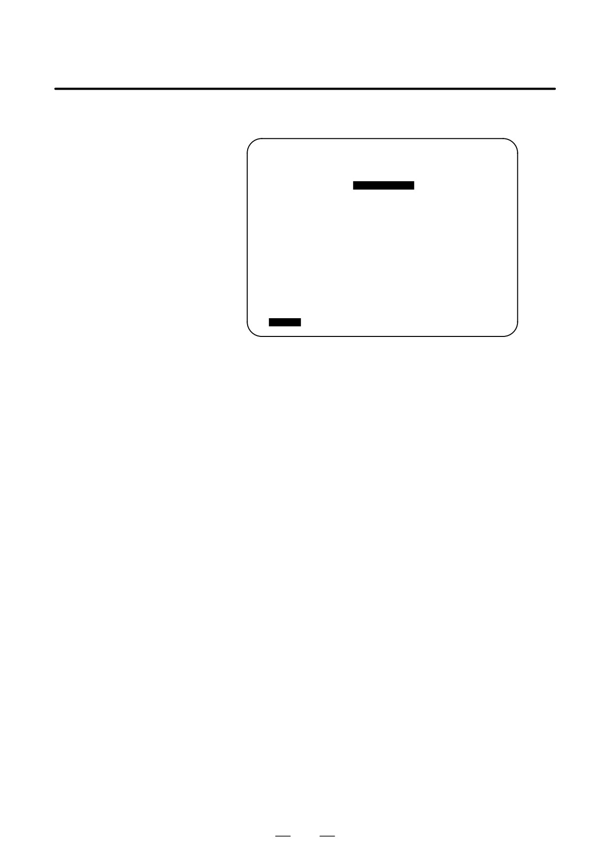
Macro instruction to describe a parameter title , the variable name, and
a comment.
VAR. : BOLT HOLE
O0001 N00000
NO. NAME
DATA
COMMENT
500 TOOL
0.000
501 STANDARD X
0.000
*BOLT HOLE
502 STANDARD Y
0.000
CIRCLE*
503 RADIUS
0.000
SET PATTERN
504 S. ANGL
0.000
DATA TO VAR.
505 HOLES NO
0.000
NO.500-505.
506
0.000
507
0.000
ACTUAL POSITION (RELATIVE)
X
0.000
Y
0.000
Z
0.000
> _
MDI **** *** ***
16:05:59
[ MACRO ] [ MENU ] [ OPR
] [
] [(OPRT)]
O9501 ;
N1 G65 H92 P066079 Q076084 R032072 I079076 J069032 ;
VAR : BOLT HOLE
N2 G65 H93 P500 Q084079 R079076 ;
#500 TOOL
N3 G65 H93 P501 Q075073 R074085 I078032 J088032 ;
#501 KIJUN X
N4 G65 H93 P502 Q075073 R074085 I078032 J089032 ;
#502 KIJUN Y
N5 G65 H93 P503 Q082065 R068073 I085083 ;
#503 RADIUS
N6 G65 H93 P504 Q083046 R032065 I078071 J076032 ;
#504 S.ANGL
N7 G65 H93 P505 Q072079 R076069 I083032 J078079 K046032 ;
#505 HOLES NO
N8 G65 H94 ;
Comment
N9 G65 H94 P042066 Q079076 R084032 I072079 J076069 ;
*BOLT HOLE
N10 G65 H94 R032067 I073082 J067076 K069042 ;
CIRCLE*
N11 G65 H94 P083069 Q084032 080065 I084084 J069082 K078032 ;
SET PATTERN
N12 G65 H94 P068065 Q084065 R032084 I079032 J086065 K082046 ;
DATA NO VAR.
N13 G65 H94 P078079 Q046053 R048048 I045053 J048053 K046032;
No.500-505
N14 M99 ;
370
16. PATTERN DATA INPUT
B-64124EN/01
PROGRAMMING
FUNCTION
16.3
CHARACTERS AND
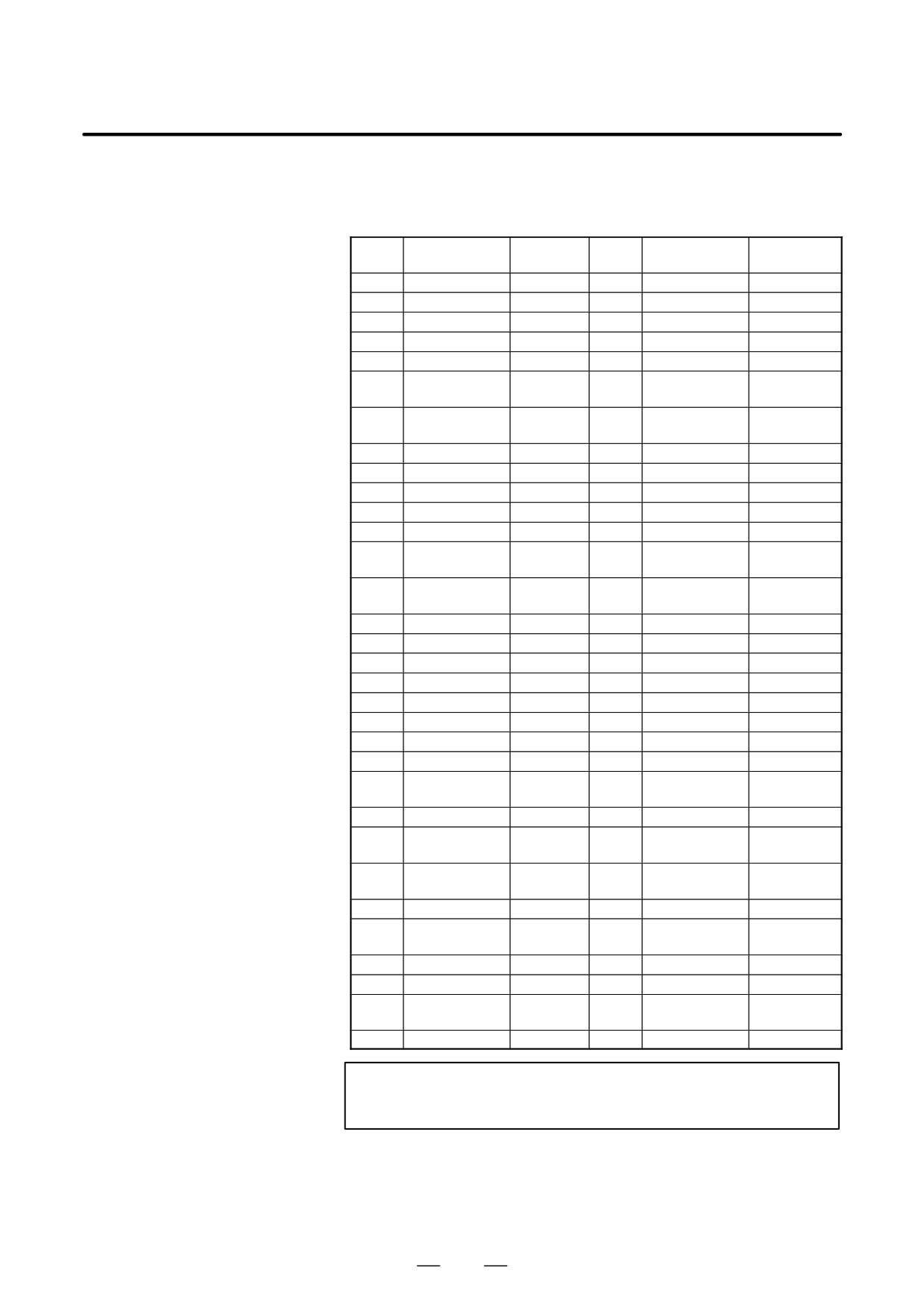
Table. 16.3 (a) Characters and codes to be used
for the pattern data input function
CODES TO BE USED
Char-
Char-
Code
Comment
Code
Comment
FOR THE PATTERN
acter
acter
A
065
6
054
DATA INPUT
B
066
7
055
FUNCTION
C
067
8
056
D
068
9
057
E
069
032
Space
F
070
!
033
Exclama-
tion mark
G
071
”
034
Quotation
mark
H
072
#
035
Hash sign
I
073
$
036
Dollar sign
J
074
%
037
Percent
K
075
&
038
Ampersand
L
076
’
039
Apostrophe
M
077
(
040
Left
parenthesis
N
078
)
041
Right
parenthesis
O
079
042
Asterisk
P
080
+
043
Plus sign
Q
081
,
044
Comma
R
082
-
045
Minus sign
S
083
046
Period
T
084
/
047
Slash
U
085
:
058
Colon
V
086
;
059
Semicolon
W
087
<
060
Left angle
bracket
X
088
=
061
Equal sign
Y
089
>
062
Right angle
bracket
Z
090
?
063
Question
mark
0
048
@
064
HAt”mark
1
049
[
091
Left square
bracket
2
050
^
092
3
051
¥
093
Yen sign
4
052
]
094
Right squar
bracket
5
053
_
095
Underscore
NOTE
Right and left parentheses cannot be used.
371
16. PATTERN DATA INPUT
FUNCTION
PROGRAMMING
B-64124EN/01
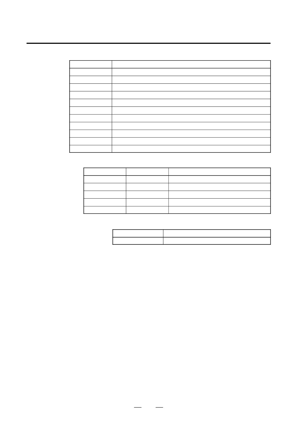
Table 16.3 (b) Numbers of subprograms employed in the pattern data input function
Subprogram No.
Function
O9500
Specifies character strings displayed on the pattern data menu.
O9501
Specifies a character string of the pattern data corresponding to pattern No.1
O9502
Specifies a character string of the pattern data corresponding to pattern No.2
O9503
Specifies a character string of the pattern data corresponding to pattern No.3
O9504
Specifies a character string of the pattern data corresponding to pattern No.4
O9505
Specifies a character string of the pattern data corresponding to pattern No.5
O9506
Specifies a character string of the pattern data corresponding to pattern No.6
O9507
Specifies a character string of the pattern data corresponding to pattern No.7
O9508
Specifies a character string of the pattern data corresponding to pattern No.8
O9509
Specifies a character string of the pattern data corresponding to pattern No.9
O9510
Specifies a character string of the pattern data corresponding to pattern No.10
Table. 16.3 (c) Macro instructions used in the pattern data input function
G code
H code
Function
G65
H90
Specifies the menu title.
G65
H91
Specifies the pattern name.
G65
H92
Specifies the pattern data title.
G65
G93
Specifies the variable name.
G65
H94
Specifies the comment.
Table. 16.3 (d) System variables employed in the pattern data input function
System variable
Function
#5900
Pattern No. selected by user.
372