FANUC Series 0i-MC. OPERATOR’S MANUAL - page 7
13. FUNCTIONS TO SIMPLIFY
B-64124EN/01
PROGRAMMING
PROGRAMMING
13.1.9
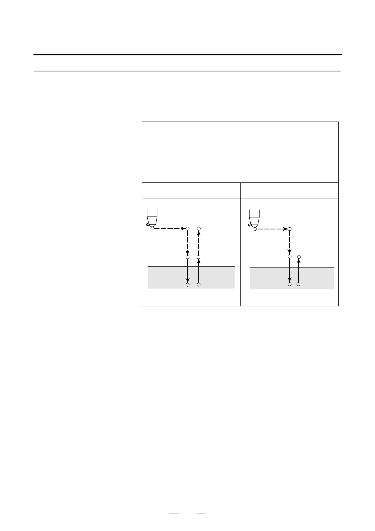
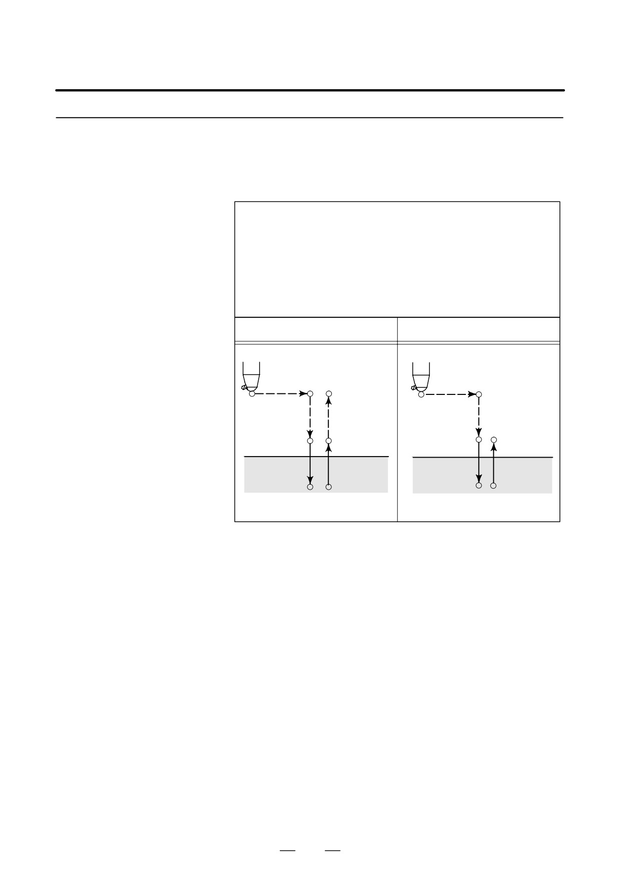
This cycle is used to bore a hole.
Boring Cycle
(G85)
Format
G85 X_ Y_ Z_ R_ F_ K_ ;
X_ Y_ : Hole position data
Z_ : The distance from point R to the bottom of the hole
R_ : The distance from the initial level to point R level
F_ : Cutting feed rate
K_ : Number of repeats (if required)
G85 (G98)
G85 (G99)
Initial level
Point R level
Point R
Point R
Point Z
Point Z
Explanations
After positioning along the X- and Y- axes, rapid traverse is performed
to point R.
Drilling is performed from point R to point Z.
When point Z has been reached, cutting feed is performed to return to
point R.
Before specifying G85, use a miscellaneous function (M code) to rotate
the spindle.
When the G85 command and an M code are specified in the same block,
the M code is executed at the time of the first positioning operation. The
system then proceeds to the next drilling operation.
When K is used to specify the number of repeats, the M code is executed
for the first hole only; for the second and subsequent holes, the M code
is not executed.
When a tool length offset (G43, G44, or G49) is specified in the canned
cycle, the offset is applied at the time of positioning to point R.
163
13. FUNCTIONS TO SIMPLIFY
PROGRAMMING
PROGRAMMING
B-64124EN/01
Limitations
D Axis switching
Before the drilling axis can be changed, the canned cycle must be
canceled.
D Drilling
In a block that does not contain X, Y, Z, R, or any other axes, drilling is
not performed.
D Cancel
Do not specify a G code of the 01 group (G00 to G03 or G60 (when the
MDL bit (bit 0 of parameter 5431) is set to 1)) and G85 in a single block.
Otherwise, G85 will be canceled.
D Tool offset
In the canned cycle mode, tool offsets are ignored.
Examples
M3 S100 ;
Cause the spindle to start rotating.
G90 G99 G85 X300. Y-250. Z-150. R-120. F120. ;
Position, drill hole 1, then return to point R.
Y-550. ;
Position, drill hole 2, then return to point R.
Y-750. ;
Position, drill hole 3, then return to point R.
X1000. ;
Position, drill hole 4, then return to point R.
Y-550. ;
Position, drill hole 5, then return to point R.
G98 Y-750. ;
Position, drill hole 6, then return to the initial
level.
G80 G28 G91 X0 Y0 Z0 ; Return to the reference position return
M5 ;
Cause the spindle to stop rotating.
164
13. FUNCTIONS TO SIMPLIFY
B-64124EN/01
PROGRAMMING
PROGRAMMING
13.1.10
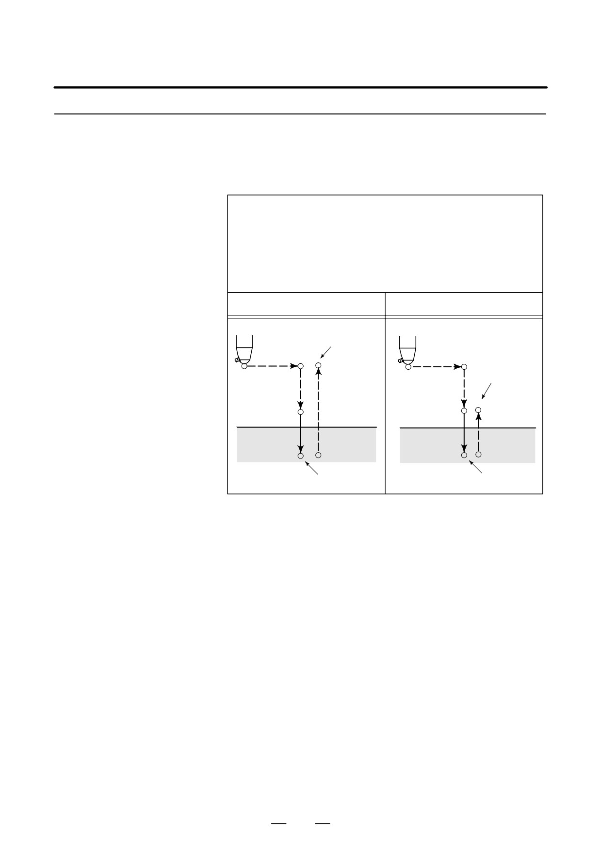
This cycle is used to bore a hole.
Boring Cycle
(G86)
Format
G86 X_ Y_ Z_ R_ F_ K_ ;
X_ Y_ : Hole position data
Z_ : The distance from point R to the bottom of the hole
R_ : The distance from the initial level to point R level
F_ : Cutting feed rate
K_ : Number of repeats (if required)
G86 (G98)
G86 (G99)
Spindle CW
Initial level
Spindle CW
Point R
Point R
Point R level
Point Z
Point Z
Spindle stop
Spindle stop
Explanations
After positioning along the X- and Y-axes, rapid traverse is performed
to point R.
Drilling is performed from point R to point Z.
When the spindle is stopped at the bottom of the hole, the tool is retracted
in rapid traverse.
Before specifying G86, use a miscellaneous function (M code) to rotate
the spindle.
When the G86 command and an M code are specified in the same block,
the M code is executed at the time of the first positioning operation.
The system then proceeds to the next drilling operation.
When K is used to specify the number of repeats, the M code is executed
for the first hole only; for the second and subsequent holes, the M code
is not executed.
When a tool length offset (G43, G44, or G49) is specified in the canned
cycle, the offset is applied at the time of positioning to point R.
165
13. FUNCTIONS TO SIMPLIFY
PROGRAMMING
PROGRAMMING
B-64124EN/01
Limitations
D Axis switching
Before the drilling axis can be changed, the canned cycle must be
canceled.
D Drilling
In a block that does not contain X, Y, Z, R, or any other axes, drilling is
not performed.
D Cancel
Do not specify a G code of the 01 group (G00 to G03 or G60 (when the
MDL bit (bit 0 of parameter 5431) is set to 1)) and G86 in a single block.
Otherwise, G86 will be canceled.
D Tool offset
In the canned cycle mode, tool offsets are ignored.
Examples
M3 S2000 ;
Cause the spindle to start rotating.
G90 G99 G86 X300. Y-250. Z-150. R-100. F120. ;
Position, drill hole 1, then return to point R.
Y-550. ;
Position, drill hole 2, then return to point R.
Y-750. ;
Position, drill hole 3, then return to point R.
X1000. ;
Position, drill hole 4, then return to point R.
Y-550. ;
Position, drill hole 5, then return to point R.
G98 Y-750. ;
Position, drill hole 6, then return to the initial
level.
G80 G28 G91 X0 Y0 Z0 ; Return to the reference position return
M5 ;
Cause the spindle to stop rotating.
166
13. FUNCTIONS TO SIMPLIFY
B-64124EN/01
PROGRAMMING
PROGRAMMING
13.1.11
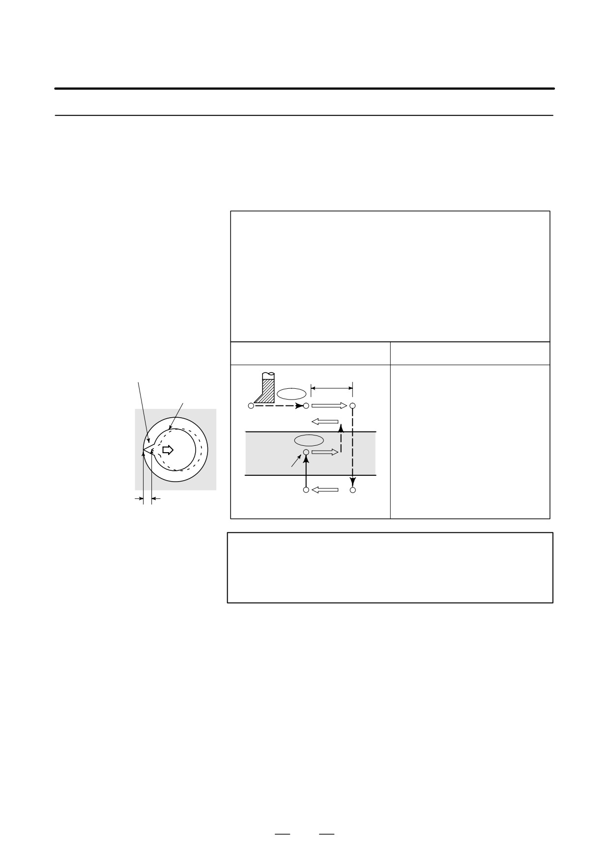
This cycle performs accurate boring.
Back Boring Cycle
(G87)
Format
G87 X_ Y_ Z_ R_ Q_ P_ F_ K_ ;
X_ Y_ : Hole position data
Z_ : The distance from the bottom of the hole to point Z
R_ : The distance from the initial level to point R
(the bottom of the hole) level
Q_ : Tool shift amount
P_ : Dwell time
F_ : Cutting feed rate
K_ : Number of repeats (if required)
G87 (G98)
G87 (G99)
Oriented spindle stop
q
OSS
Tool
Spindle CW
Not used
OSS
Point Z
P
Spindle CW
Shift amount q
Point R
WARNING
Q (shift at the bottom of a hole) is a modal value retained in
canned cycles. It must be specified carefully because it is
also used as the depth of cut for G73 and G83.
167
13. FUNCTIONS TO SIMPLIFY
PROGRAMMING
PROGRAMMING
B-64124EN/01
Explanations
After positioning along the X- and Y-axes, the spindle is stopped at the
fixed rotation position. The tool is moved in the direction opposite to the
tool tip, positioning (rapid traverse) is performed to the bottom of the hole
(point R).
The tool is then shifted in the direction of the tool tip and the spindle is
rotated clockwise. Boring is performed in the positive direction along the
Z-axis until point Z is reached.
At point Z, the spindle is stopped at the fixed rotation position again, the
tool is shifted in the direction opposite to the tool tip, then the tool is
returned to the initial level. The tool is then shifted in the direction of the
tool tip and the spindle is rotated clockwise to proceed to the next block
operation.
Before specifying G87, use a miscellaneous function (M code) to rotate
the spindle.
When the G87 command and an M code are specified in the same block,
the M code is executed at the time of the first positioning operation.
The system then proceeds to the next drilling operation. When K is used
to specify the number of repeats, the M code is executed for the first hole
only; for the second and subsequent holes, the M code is not executed.
When a tool length offset (G43, G44, or G49) is specified in the canned
cycle, the offset is applied at the time of positioning to point R.
Restrictions
D Axis switching
Before the drilling axis can be changed, the canned cycle must be
canceled.
D Boring
In a block that does not contain X, Y, Z, R, or any additional axes, boring
is not performed.
D P/Q
Be sure to specify a positive value in Q. If Q is specified with a negative
value, the sign is ignored. Set the direction of shift in bits 4 (RD1) and
5 (RD2) of parameter No.5101. Specify P and Q in a block that performs
boring. If they are specified in a block that does not perform boring, they
are not stored as modal data.
D Cancel
Do not specify a G code of the 01 group (G00 to G03 or G60 (when the
MDL bit (bit 0 of parameter 5431) is set to 1)) and G87 in a single block.
Otherwise, G87 will be canceled.
D Tool offset
In the canned cycle mode, tool offsets are ignored.
Examples
M3 S500 ;
Cause the spindle to start rotating.
G90 G87 X300. Y-250.
Position, bore hole 1.
Z-120. R-150. Q5.
Orient at the initial level, then shift by 5 mm.
P1000 F120. ;
Stop at point Z for 1 s.
Y-550. ;
Position, drill hole 2.
Y-750. ;
Position, drill hole 3.
X1000. ;
Position, drill hole 4.
Y-550. ;
Position, drill hole 5.
Y-750. ;
Position, drill hole 6
G80 G28 G91 X0 Y0 Z0 ;
Return to the reference position return
M5 ;
Cause the spindle to stop rotating.
168
13. FUNCTIONS TO SIMPLIFY
B-64124EN/01
PROGRAMMING
PROGRAMMING
13.1.12
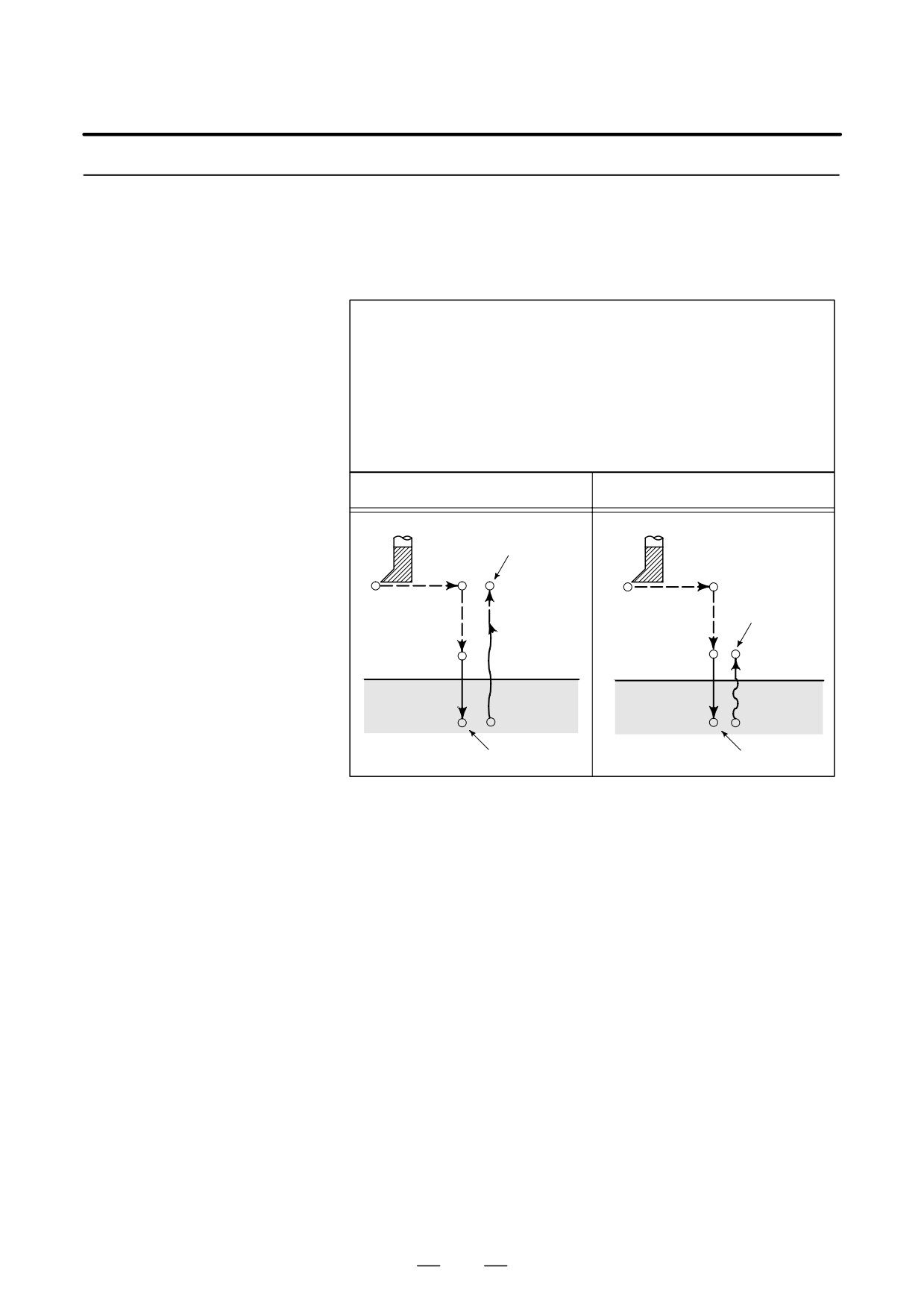
This cycle is used to bore a hole.
Boring Cycle
(G88)
Format
G88 X_ Y_ Z_ R_ P_ F_ K_ ;
X_ Y_ : Hole position data
Z_ : The distance from point R to the bottom of the hole
R_ : The distance from the initial level to point R level
P_ : Dwell time at the bottom of a hole
F_ : Cutting feed rate
K_ : Number of repeats (if required)
G88 (G98)
G88 (G99)
Spindle CW
Initial level
Spindle CW
Point R
Point R
Point R level
Point Z
Point Z
P
P
Spindle stop
Spindle stop
after dwell
after dwell
Explanations
After positioning along the X- and Y-axes, rapid traverse is performed
to point R. Boring is performed from point R to point Z. When boring
is completed, a dwell is performed, then the spindle is stopped. The tool
is manually retracted from the bottom of the hole (point Z) to point R.
At point R, the spindle is rotated clockwise, and rapid traverse is
performed to the initial level.
Before specifying G88, use a miscellaneous function (M code) to rotate
the spindle.
When the G88 command and an M code are specified in the same block,
the M code is executed at the time of the first positioning operation. The
system then proceeds to the next drilling operation.
When K is used to specify the number of repeats, the M code is executed
for the first hole only; for the second and subsequent holes, the M code
is not executed.
When a tool length offset (G43, G44, or G49) is specified in the canned
cycle, the offset is applied at the time of positioning to point R.
169
13. FUNCTIONS TO SIMPLIFY
PROGRAMMING
PROGRAMMING
B-64124EN/01
Limitations
D Axis switching
Before the drilling axis can be changed, the canned cycle must be
canceled.
D Drilling
In a block that does not contain X, Y, Z, R, or any other axes, drilling is
not performed.
D P
Specify P in blocks that perform drilling. If it is specified in a block that
does not perform drilling, it cannot be stored as modal data.
D Cancel
Do not specify a G code of the 01 group (G00 to G03 or G60 (when the
MDL bit (bit 0 of parameter 5431) is set to 1)) and G88 in a single block.
Otherwise, G88 will be canceled.
D Tool offset
In the canned cycle mode, tool offsets are ignored.
Examples
M3 S2000 ;
Cause the spindle to start rotating.
G90 G99 G88 X300. Y-250. Z-150. R-100. P1000 F120. ;
Position, drill hole 1, return to point R
then stop at the bottom of the hole for 1 s.
Y-550. ;
Position, drill hole 2, then return to point R.
Y-750. ;
Position, drill hole 3, then return to point R.
X1000. ;
Position, drill hole 4, then return to point R.
Y-550. ;
Position, drill hole 5, then return to point R.
G98 Y-750. ;
Position, drill hole 6, then return to the initial
level.
G80 G28 G91 X0 Y0 Z0 ; Return to the reference position return
M5 ;
Cause the spindle to stop rotating.
170
13. FUNCTIONS TO SIMPLIFY
B-64124EN/01
PROGRAMMING
PROGRAMMING
13.1.13
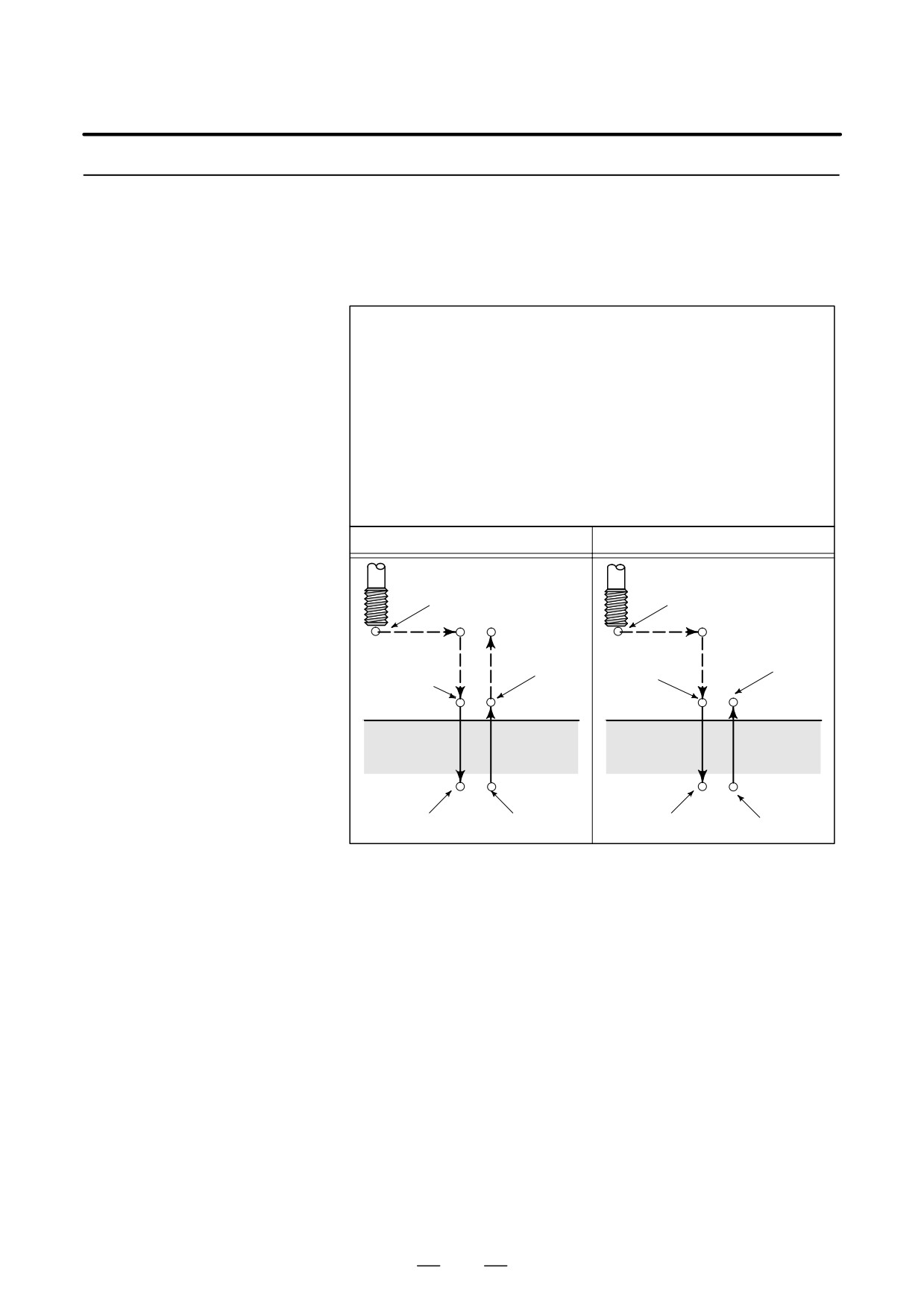
This cycle is used to bore a hole.
Boring Cycle
(G89)
Format
G89 X_ Y_ Z_ R_ P_ F_ K_ ;
X_ Y_ : Hole position data
Z_ : The distance from point R to the bottom of the hole
R_ : The distance from the initial level to point R level
P_ : Dwell time at the bottom of a hole
F_ : Cutting feed rate
K_ : Number of repeats (if required)
G89 (G98)
G89 (G99)
Initial level
Point R level
Point R
Point R
Point Z
Point Z
P
P
Explanations
This cycle is almost the same as G85. The difference is that this cycle
performs a dwell at the bottom of the hole.
Before specifying G89, use a miscellaneous function (M code) to rotate
the spindle.
When the G89 command and an M code are specified in the same block,
the M code is executed at the time of the first positioning operation. The
system then proceeds to the next drilling operation.
When K is used to specify the number of repeats, the M code is executed
for the first hole only; for the second and subsequent holes, the M code
is not executed.
When a tool length offset (G43, G44, or G49) is specified in the canned
cycle, the offset is applied at the time of positioning to point R.
171
13. FUNCTIONS TO SIMPLIFY
PROGRAMMING
PROGRAMMING
B-64124EN/01
Limitations
D Axis switching
Before the drilling axis can be changed, the canned cycle must be
canceled.
D Drilling
In a block that does not contain X, Y, Z, R, or any other axes, drilling is
not performed.
D P
Specify P in blocks that perform drilling. If it is specified in a block that
does not perform drilling, it cannot be stored as modal data.
D Cancel
Do not specify a G code of the 01 group (G00 to G03 or G60 (when the
MDL bit (bit 0 of parameter 5431) is set to 1)) and G89 in a single block.
Otherwise, G89 will be canceled.
D Tool offset
In the canned cycle mode, tool offsets are ignored.
Examples
M3 S100 ;
Cause the spindle to start rotating.
G90 G99 G89 X300. Y-250. Z-150. R-120. P1000 F120. ;
Position, drill hole 1, return to point R
then stop at the bottom of the hole for 1 s.
Y-550. ;
Position, drill hole 2, then return to point R.
Y-750. ;
Position, drill hole 3, then return to point R.
X1000. ;
Position, drill hole 4, then return to point R.
Y-550. ;
Position, drill hole 5, then return to point R.
G98 Y-750. ;
Position, drill hole 6, then return to the initial
level.
G80 G28 G91 X0 Y0 Z0 ; Return to the reference position return
M5 ;
Cause the spindle to stop rotating.
172

13. FUNCTIONS TO SIMPLIFY
B-64124EN/01
PROGRAMMING
PROGRAMMING
13.1.14
G80 cancels canned cycles.
Canned Cycle Cancel
(G80)
Format
G80 ;
Explanations
All canned cycles are canceled to perform normal operation. Point R and
point Z are cleared. This means that R = 0 and Z = 0 in incremental mode.
Other drilling data is also canceled (cleared).
Examples
M3 S100 ;
Cause the spindle to start rotating.
G90 G99 G88 X300. Y-250. Z-150. R-120. F120. ;
Position, drill hole 1, then return to point R.
Y-550. ;
Position, drill hole 2, then return to point R.
Y-750. ;
Position, drill hole 3, then return to point R.
X1000. ;
Position, drill hole 4, then return to point R.
Y-550. ;
Position, drill hole 5, then return to point R.
G98 Y-750. ; Position, drill hole 6, then return to the initial level.
G80 G28 G91 X0 Y0 Z0 ;
Return to the reference position return,
canned cycle cancel
M5 ;
Cause the spindle to stop rotating.
173
13. FUNCTIONS TO SIMPLIFY
PROGRAMMING
PROGRAMMING
B-64124EN/01
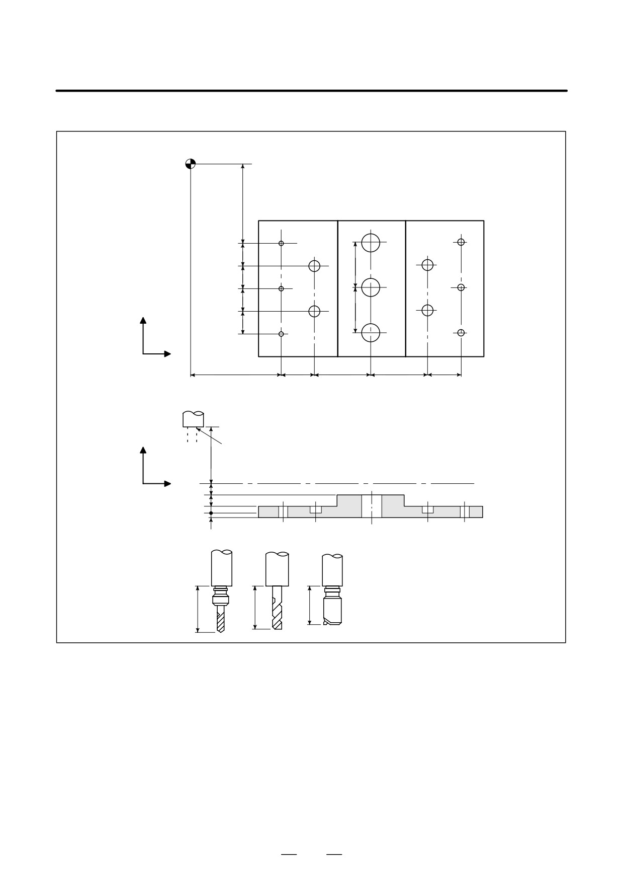
Program example using tool length offset and canned cycles
Reference position
350
#1
#11
#6
100
#7
#10
100
#2
#12
#5
100
#8
#9
Y
200
100
#3
#13
#4
X
400
150
250
250
150
# 11 to 16 Drilling of a 10mm diameter hole
# 17 to 10 Drilling of a 20mm diameter hole
# 11 to 13 Boring of a 95mm diameter hole(depth 50 mm)
Z
Retract position
250
Initial level
X
50
50
30
20
T 11
T 15
T 31
200
190
150
174

13. FUNCTIONS TO SIMPLIFY
B-64124EN/01
PROGRAMMING
PROGRAMMING
Offset value +200.0 is set in offset No.11, +190.0 is set in offset No.15, and +150.0 is set in offset No.31
Program example
;
N001
G92X0Y0Z0;
Coordinate setting at reference position
N002
G90 G00 Z250.0 T11 M6;
Tool change
N003
G43 Z0 H11;
Initial level, tool length offset
N004
S30 M3
Spindle start
N005
G99 G81X400.0 R Y-350.0
Z-153,0R-97.0 F120;
Positioning, then #1 drilling
N006
Y-550.0;
Positioning, then #2 drilling and point R level return
N007
G98Y-750.0;
Positioning, then #3 drilling and initial level return
N008
G99X1200.0;
Positioning, then #4 drilling and point R level return
N009
Y-550.0;
Positioning, then #5 drilling and point R level return
N010
G98Y-350.0;
Positioning, then #6 drilling and initial level return
N011
G00X0Y0M5;
Reference position return, spindle stop
N012
G49Z250.0T15M6;
Tool length offset cancel, tool change
N013
G43Z0H15;
Initial level, tool length offset
N014
S20M3;
Spindle start
N015
G99G82X550.0Y-450.0
Positioning, then #7 drilling, point R level return
Z-130.0R-97.0P300F70;
N016
G98Y-650.0;
Positioning, then #8 drilling, initial level return
N017
G99X1050.0;
Positioning, then #9 drilling, point R level return
N018
G98Y-450.0;
Positioning, then #10 drilling, initial level return
N019
G00X0Y0M5;
Reference position return, spindle stop
N020
G49Z250.0T31M6;
Tool length offset cancel, tool change
N021
G43Z0H31;
Initial level, tool length offset
N022
S10M3;
Spindle start
N023
G85G99X800.0Y-350.0
Positioning, then #11 drilling, point R level return
Z-153.0R47.0F50;
N024
G91Y-200.0K2;
Positioning, then #12, 13 drilling. point R level return
N025
G28X0Y0M5;
Reference position return, spindle stop
N026
G49Z0;
Tool length offset cancel
N027
M0;
Program stop
175
13. FUNCTIONS TO SIMPLIFY
PROGRAMMING
PROGRAMMING
B-64124EN/01
The tapping cycle (G84) and left-handed tapping cycle (G74) may be
13.2
performed in standard mode or rigid tapping mode.
RIGID TAPPING
In standard mode, the spindle is rotated and stopped along with a
movement along the tapping axis using miscellaneous functions M03
(rotating the spindle clockwise), M04
(rotating the spindle
counterclockwise), and M05 (stopping the spindle) to perform tapping.In
rigid mode, tapping is performed by controlling the spindle motor as if
it were a servo motor and by interpolating between the tapping axis and
spindle.
When tapping is performed in rigid mode, the spindle rotates one turn
every time a certain feed (thread lead) which takes place along the tapping
axis. This operation does not vary even during acceleration or
deceleration.
Rigid mode eliminates the need to use a floating tap required in the
standard tapping mode, thus allowing faster and more precise tapping.
176
13. FUNCTIONS TO SIMPLIFY
B-64124EN/01
PROGRAMMING
PROGRAMMING
13.2.1
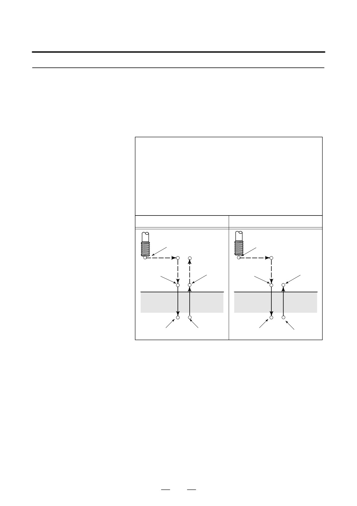
When the spindle motor is controlled in rigid mode as if it were a servo
motor, a tapping cycle can be sped up.
Rigid Tapping
(G84)
Format
G84 X_ Y_ Z_ R_ P_ F_ K_ ;
X_ Y_ : Hole position data
Z_ : The distance from point R to the bottom of the hole and the
position of the bottom of the hole
R_ : The distance from the initial level to point R level
P_ : Dwell time at the bottom of the hole and at point R when a
return is made
F_ : Cutting feedrate
K_ : Number of repeats (Only for necessity of repeat)
G84.2 X_ Y_ Z_ R_ P_ F_ L_ ;
(FS10/11 format)
L_
: Number of repeats (only for necessity of repeat)
G84(G98)
G84(G99)
Spindle stop
Spindle stop
Initial level
Operation1
Operation6
Operation2
Spindle stop
Spindle CW
Spindle
Spindle CW
P
P
stop
Point R level
Point R
Point R
Operation3
Operation5
Point Z
Point Z
P
P
Operation4
Spindle stop
Spindle CCW
Spindle stop
Spindle CCW
Explanations
After positioning along the X- and Y-axes, rapid traverse is performed
to point R.
Tapping is performed from point R to point Z. When tapping is
completed, the spindle is stopped and a dwell is performed . The spindle
is then rotated in the reverse direction, the tool is retracted to point R, then
the spindle is stopped. Rapid traverse to initial level is then performed.
While tapping is being performed, the feedrate override and spindle
override are assumed to be 100%.
However, the speed for extraction (operation 5) can be overridden by up
to 2000% depending on the setting at bit 4 (DOV) of parameter No.5200,
bit 3 (OVU) of parameter No.5201, and parameter No.5211.
D Rigid mode
Rigid mode can be specified using any of the following methods:
⋅Specify M29 S***** before a tapping command.
⋅Specify M29 S***** in a block which contains a tapping
command.
⋅Specify G84 for rigid tapping (parameter G84 No. 5200 #0 set to 1).
177
13. FUNCTIONS TO SIMPLIFY
PROGRAMMING
PROGRAMMING
B-64124EN/01
D Thread lead
In feed-per-minute mode, the thread lead is obtained from the
expression, feedrate × spindle speed. In feed-per-revolution mode, the
thread lead equals the feedrate speed.
D Tool length
If a tool length compensation (G43, G44, or G49) is specified in the
compensation
canned cycle, the offset is applied at the time of positioning to point R.
D FS10/11-format
Rigid tapping can be performed using FS10/11-format commands.
command
These commands are used according to the sequence (including data
transfer to and from the PMC), limitations, and other rigid tapping
conditions for the FS 0i.
Limitations
D Axis switching
Before the drilling axis can be changed, the canned cycle must be
canceled. If the drilling axis is changed in rigid mode, P/S alarm (No.
206) is issued.
D S command
If a speed higher than the maximum speed for the gear being used is
specified, P/S alarm (No. 200) is issued.
The S command, which is specified at rigid tapping, is cleared at
commanding Rigid Tapping Cancel and the condition is the same that S0
is commanded.
D Distribution amount for
For an analog spindle control circuit:
the spindle
Upon specifying a speed command requiring more than 4096 pulses, in
detection units, within 8 ms, a P/S alarm (No.202) is issued because the
result of such an operation is unpredictable.
For a serial spindle:
Upon specifying a speed command requiring more than 32767 pulses, in
detection units, within 8 ms, a P/S alarm (No.202) is issued because the
result of such an operation is unpredictable.
D F command
If a value exceeding the upper limit of cutting feedrate is specified, P/S
alarm (No. 011) is issued.
D Unit of F command
Metric input
Inch input
Remarks
G94
1 mm/min
0.01 inch/min
Decimal point programming
allowed
G95
0.01 mm/rev
0.0001 inch/rev
Decimal point programming
allowed
D M29
If an S command and axis movement are specified between M29 and G84,
P/S alarm (No. 203) is issued. If M29 is specified in a tapping cycle, P/S
alarm (No. 204) is issued.
D P
Specify P in a block that performs drilling. If R is specified in a
non-drilling block, it is not stored as modal data.
D Cancel
Do not specify a G code of the 01 group (G00 to G03 or G60 (when the
MDL bit (bit 0 of parameter 5431) is set to 1)) and G84 in a single block.
Otherwise, G84 will be canceled.
D Tool offset
In the canned cycle mode, tool offsets are ignored.
178
13. FUNCTIONS TO SIMPLIFY
B-64124EN/01
PROGRAMMING
PROGRAMMING
D Program restart
Any program cannot be resumed during rigid tapping.
Examples
Z-axis feedrate 1000 mm/min
Spindle speed 1000 min-1
Thread lead
1.0 mm
<Programming of feed per minute>
G94 ;
Specify a feed-per-minute command.
G00 X120.0 Y100.0 ;
Positioning
M29 S1000 ;
Rigid mode specification
G84 Z-100.0 R-20.0 F1000 ; Rigid tapping
<Programming of feed per revolution>
G95 ;
Specify a feed-per-revolution command.
G00 X120.0 Y100.0 ;
Positioning
M29 S1000 ;
Rigid mode specification
G84 Z-100.0 R-20.0 F1.0 ;
Rigid tapping
179
13. FUNCTIONS TO SIMPLIFY
PROGRAMMING
PROGRAMMING
B-64124EN/01
13.2.2
When the spindle motor is controlled in rigid mode as if it were a servo
motor, tapping cycles can be sped up.
Left-handed Rigid
Tapping Cycle
(G74)
Format
G74 X_ Y_ Z_ R_ P_ F_ K_ ;
X_ Y_ : Hole position data
Z_ : The distance from point R to the bottom of the hole and
the position of the bottom of the hole
R_ : The distance from the initial level to point R level
P_ : Dwell time at the bottom of the hole and at point R when
return is made.
F_ : Cutting feedrate
K_ : Number of repeats (Only for necessity of repeat)
G84.3 X_ Y_ Z_ R_ P_ F_ L_ ; (FS15 format)
L_
: Number of repeats (Only for necessity of repeat)
G74 (G98)
G74 (G99)
Spindle stop
Spindle stop
Initial level
Operation1
Operation2
Operation6
Spindle
Spindle
Spindle
Spindle
P
CCW
stop
P
stop
CCW
Point R
Point R level
Point R
Point R level
Operation3
Operation5
Point Z
Point Z
P
P
Spindle stop
Operation4 Spindle CW
Spindle stop
Spindle CW
Explanations
After positioning along the X- and Y-axes, rapid traverse is performed
to point R.
Tapping is performed from point R to point Z. When tapping is
completed, the spindle is stopped and a dwell is performed. The spindle
is then rotated in the normal direction, the tool is retracted to point R, then
the spindle is stopped. Rapid traverse to initial level is then performed.
While tapping is being performed, the feedrate override and spindle
override are assumed to be 100%.
However, the speed for extraction (operation 5) can be overridden by up
to 2000% depending on the setting at bit 4 (DOV) of parameter 5200, bit
3 (OVU) of parameter No.5201, and parameter 5211.
D Rigid mode
Rigid mode can be specified using any of the following methods:
⋅ Specify M29 S***** before a tapping command.
⋅ Specify M29 S***** in a block which contains a tapping command.
⋅ Specify G84 for rigid tapping. (parameter G84 No. 5200#0 set to1).
180
13. FUNCTIONS TO SIMPLIFY
B-64124EN/01
PROGRAMMING
PROGRAMMING
D Thread lead
In feed-per-minute mode, the thread lead is obtained from the
expression, feedrate × spindle speed. In feed-per-revolution mode, the
thread lead equals the feedrate.
D Tool length
If a tool length offset (G43, G44, or G49) is specified in the canned cycle,
compensation
the offset is applied at the time of positioning to point R.
D FS10/11-format
Rigid tapping can be performed using FS10/11-format commands.
command
These commands are used according to the sequence (including data
transfer to and from the PMC), limitations, and other rigid tapping
conditions for the FS 0i.
Limitations
D Axis switching
Before the drilling axis can be changed, the canned cycle must be
canceled. If the drilling axis is changed in rigid mode,P/S alarm (No.
206) is issued.
D S command
Specifying a rotation speed exceeding the maximum speed for the gear
used causes P/S alarm (No. 200).
The S command, which is specified at rigid tapping, is cleared at
commanding Rigid Tapping Cancel and the condition is the same that S0
is commanded.
D Distribution amount for
For an analog spindle control circuit:
the spindle
Upon specifying a speed command requiring more than 4096 pulses, in
detection units, within 8 ms, a P/S alarm (No.202) is issued because the
result of such an operation is unpredictable.
For a serial spindle:
Upon specifying a speed command requiring more than 32767 pulses, in
detection units, within 8 ms, a P/S alarm (No.202) is issued because the
result of such an operation is unpredictable.
D F command
Specifying a value that exceeds the upper limit of cutting feedrate causes
P/S alarm (No. 011).
D Unit of F command
Metric input
Inch input
Remarks
G94
1 mm/min
0.01 inch/min
Decimal point
programming allowed
G95
0.01 mm/rev
0.0001 inch/rev
Decimal point
programming allowed
D M29
Specifying an S command or axis movement between M29 and G74
causes P/S alarm (No. 203).
Then, specifying M29 in the tapping cycle causes P/S alarm (No. 204).
D P
Specify P in a block that performs drilling. If R is specified in a
non-drilling block, it ss not stored as modal data.
D Cancel
Do not specify a G code of the 01 group (G00 to G03 or G60 (when the
MDL bit (bit 0 of parameter 5431) is set to 1)) and G74 in a single block.
Otherwise, G74 will be canceled.
D Tool offset
In the canned cycle mode, tool offsets are ignored.
181
13. FUNCTIONS TO SIMPLIFY
PROGRAMMING
PROGRAMMING
B-64124EN/01
Examples
Z-axis feedrate 1000 mm/min
Spindle speed 1000 min-1
Thread lead
1.0 mm
<Programming for feed per minute>
G94 ;
Specify a feed-per-minute command.
G00 X120.0 Y100.0 ;
Positioning
M29 S1000 ;
Rigid mode specification
G84 Z-100.0 R-20.0 F1000 ; Rigid tapping
<Programming for feed per revolution>
G95 ;
Specify a feed-per-revolution command.
G00 X120.0 Y100.0 ;
Positioning
M29 S1000 ;
Rigid mode specification
G74 Z-100.0 R-20.0 F1.0 ;
Rigid tapping
182
13. FUNCTIONS TO SIMPLIFY
B-64124EN/01
PROGRAMMING
PROGRAMMING
13.2.3
Tapping a deep hole in rigid tapping mode may be difficult due to chips
sticking to the tool or increased cutting resistance. In such cases, the peck
Peck Rigid Tapping
rigid tapping cycle is useful.
Cycle (G84 or G74)
In this cycle, cutting is performed several times until the bottom of the
hole is reached. Two peck tapping cycles are available: High-speed peck
tapping cycle and standard peck tapping cycle. These cycles are selected
using the PCP bit (bit 5) of parameter 5200.
Format
G84 (or G74) X_ Y_ Z_ R_ P_ Q_ F_ K_ ;
X_ Y_ : Hole position data
Z_ : The distance from point R to the bottom of the hole and the
position of the bottom of the hole
R_ : The distance from the initial level to point R level
P_ : Dwell time at the bottom of the hole and at point R when a
return is made
Q_ : Depth of cut for each cutting feed
F_ : The cutting feedrate
K_ : Number of repeats
G84, G74 (G98)
G84, G74 (G99)
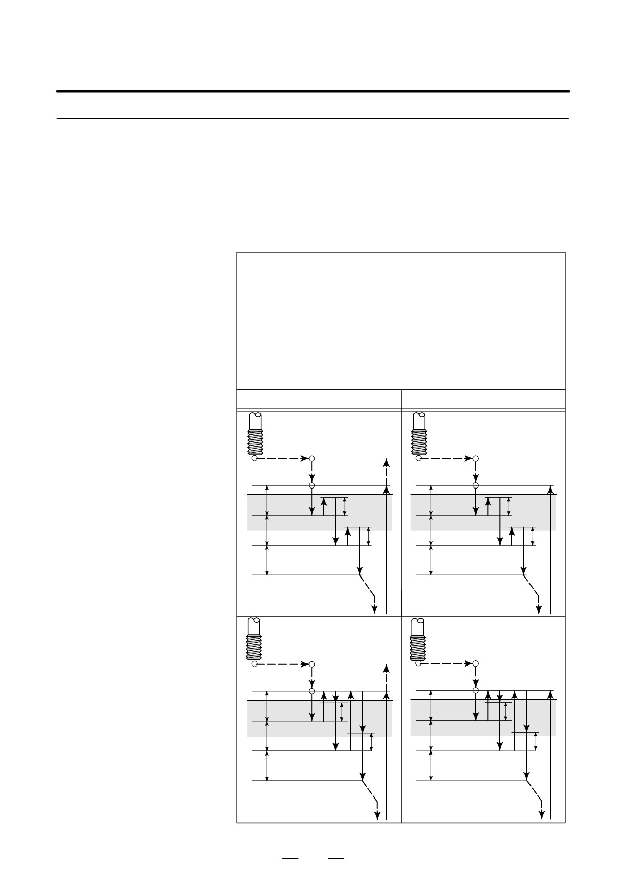
⋅ High-speed peck tapping cycle
d=retraction distance
(Parameter PCP(No.5200#5=0))
Initial level
(1) The tool operates at a normal
cutting feedrate. The normal time
Point R level
constant is used.
Point R
Point R level
Point R
(2) Retraction can be overridden.
(1)
(1)
q
q
The retraction time constant is
d
d
(2)
(2)
used.
q
q
d
d
q
q
Point Z
Point Z
⋅ Peck tapping cycle
d=cutting start distance
(Parameter PCP(No.5200#5=1))
Initial level
(1) The tool operates at a normal
cutting feedrate. The normal time
constant is used.
Point R level
Point R
Point R level
Point R
(2) Retraction can be overridden.
(3)
(3)
(1)
(1)
The retraction time constant is
q
q
used.
(2)
d
(2)
d
(3) Retraction can be overridden.
q
q
The normal time constant is used.
d
d
During a rigid tapping cycle, in-position
q
q
check is performed at the end of each
operation of (1) and (2) in the peck tap-
ping cycle.
Point Z
Point Z
183

13. FUNCTIONS TO SIMPLIFY
PROGRAMMING
PROGRAMMING
B-64124EN/01
Explanations
D High-speed peck
After positioning along the X- and Y-axes, rapid traverse is performed
tapping cycle
to point R. From point R, cutting is performed with depth Q (depth of cut
for each cutting feed), then the tool is retracted by distance d. The DOV
bit
(bit
4) of parameter
5200 specifies whether retraction can be
overridden or not. When point Z has been reached, the spindle is stopped,
then rotated in the reverse direction for retraction.
Set the retraction distance, d, in parameter 5213.
D Peck tapping cycle
After positioning along the X- and Y-axes, rapid traverse is performed
to point R level. From point R, cutting is performed with depth Q (depth
of cut for each cutting feed), then a return is performed to point R. The
DOV bit (bit 4) of parameter 5200 specifies whether the retraction can be
overridden or not. The moving of cutting feedrate F is performed from
point R to a position distance d from the end point of the last cutting,
which is where cutting is restarted. For this moving of cutting feedrate
F, the specification of the DOV bit (bit 4) of parameter 5200 is also valid.
When point Z has been reached, the spindle is stopped, then rotated in the
reverse direction for retraction.
Set d (distance to the point at which cutting is started) in parameter 5213.
Limitations
D Axis switching
Before the drilling axis can be changed, the canned cycle must be
canceled. If the drilling axis is changed in rigid mode, P/S alarm (No.
206) is issued.
D S command
Specifying a rotation speed exceeding the maximum speed for the gear
used causes P/S alarm (No. 200).
The S command, which is specified at rigid tapping, is cleared at
commanding Rigid Tapping Cancel and the condition is the same that S0
is commanded.
D Distribution amount for
For an analog spindle control circuit:
the spindle
Upon specifying a speed command requiring more than 4096 pulses, in
detection units, within 8 ms, a P/S alarm (No.202) is issued because the
result of such an operation is unpredictable.
For a serial spindle:
Upon specifying a speed command requiring more than 32767 pulses, in
detection units, within 8 ms, a P/S alarm (No.202) is issued because the
result of such an operation is unpredictable.
D F command
Specifying a value that exceeds the upper limit of cutting feedrate causes
alarm (No. 011).
D Unit of F
Metric input
Inch input
Remarks
G94
1 mm/min
0.01 inch/min
Decimal point programming
allowed
G95
0.01 mm/rev
0.0001 inch/rev
Decimal point programming
allowed
D M29
Specifying an S command or axis movement between M29 and G84
causes P/S alarm (No. 203).
Then, specifying M29 in the tapping cycle causes P/S alarm (No. 204).
184

13. FUNCTIONS TO SIMPLIFY
B-64124EN/01
PROGRAMMING
PROGRAMMING
D P/Q
Specify P and Q in a block that performs drilling. If they are specified in
a block that does not perform drilling, they are not stored as modal data.
When Q0 is specified, the peck rigid tapping cycle is not performed.
D Cancel
Do not specify a group 01 G code (G00 to G03) and G73 in the same block.
If they are specified together, G73 is canceled.
D Tool offset
In the canned cycle mode, tool offsets are ignored.
13.2.4
The rigid tapping canned cycle is canceled. For how to cancel this cycle,
see II-13.1.14.
Canned Cycle Cancel
(G80)
NOTE
When Rigid Tapping Cancel is commanded, the S
command, which is used at rigid tapping, is also cleared. (It
is the same that S0 is commanded.)
Therefore, the S command, which is specified for rigid
tapping, can not be used at blocks after Rigid Tapping
Cancel. Please re-specify S command after Rigid Tapping
Cancel if necessary.
185
13. FUNCTIONS TO SIMPLIFY
PROGRAMMING
PROGRAMMING
B-64124EN/01
13.3
Canned grinding cycles make it easier for the programmer to create
programs that include grinding. With a canned grinding cycle, repetitive
CANNED GRINDING
operation peculiar to grinding can be specified in a single block with a G
CYCLE
function; without canned grinding cycles, normally more than one block
(FOR GRINDING
is required. In addition, the use of canned grinding cycles shortens the
program to save memory. The following four canned grinding cycles are
MACHINE)
available:
⋅Plunge grinding cycle (G75)
⋅Direct constant-dimension plunge grinding cycle (G77)
⋅Continuous-feed surface grinding cycle (G78)
⋅Intermittent-feed surface grinding cycle (G79)
186
13. FUNCTIONS TO SIMPLIFY
B-64124EN/01
PROGRAMMING
PROGRAMMING
13.3.1
A plunge grinding cycle is performed.
Plunge Grinding Cycle
(G75)
Format
G75 I_ J_ K_ X(Z)_ R_ F_ P_ L_ ;
I_ : Depth-of-cut 1 (A sign in the command specifies the direction
of cutting.)
J_
: Depth-of-cut 2 (A sign in the command specifies the direction
of cutting.)
K_ : Total depth of cut (A sign in the command specifies the direction
of cutting.)
X(Z)_ : Range of grinding (A sign in the command specifies the
direction of grinding.)
R_ : Feedrate for I and J
F_ : Feedrate for X (Z)
P_ : Dwell time
L_
: Grinding-wheel wear compensation (Only for continuous dressing)
G75
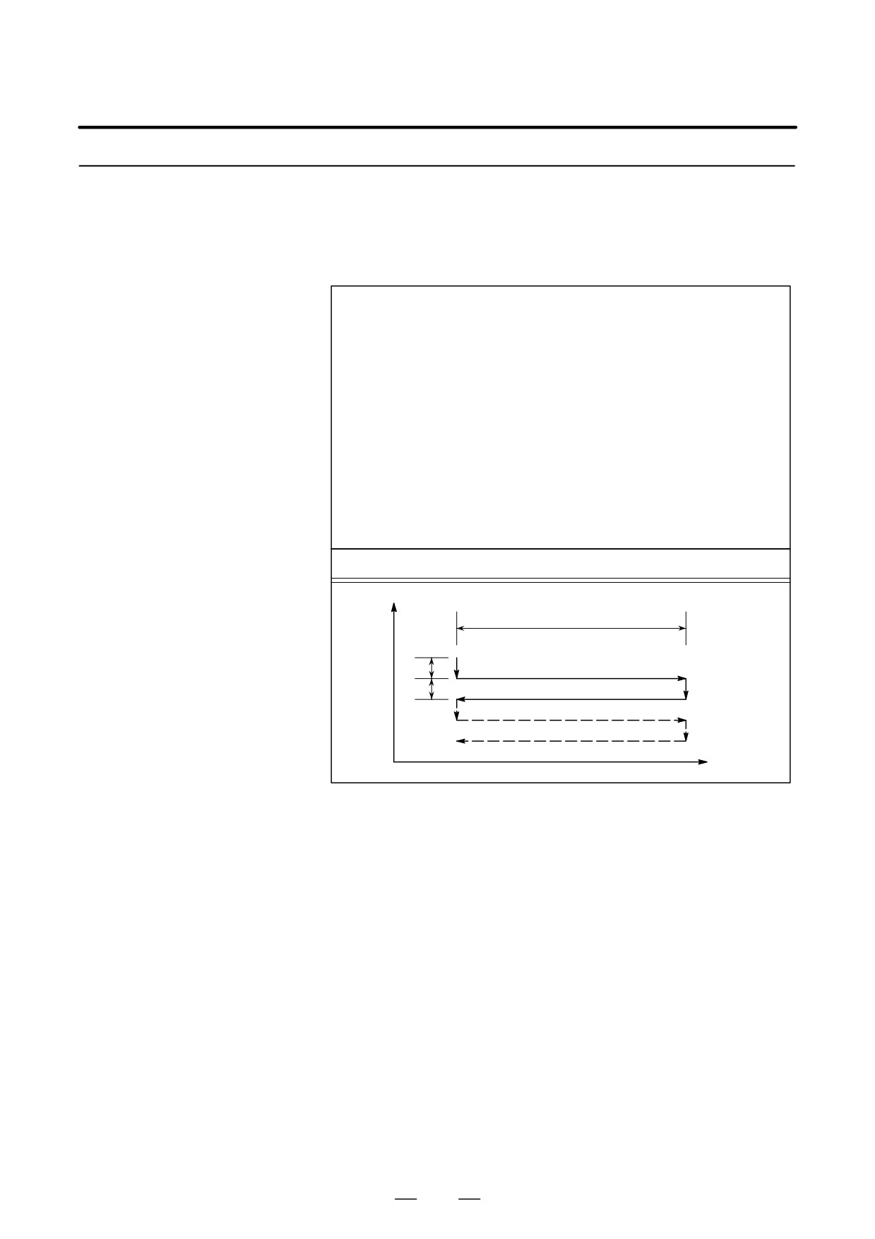
Y
X(Z)
(1) (R)
I
(3) (F)
J
(2) P
(4) (R)
(6) (F)
(5) P
X(Z)
Explanations
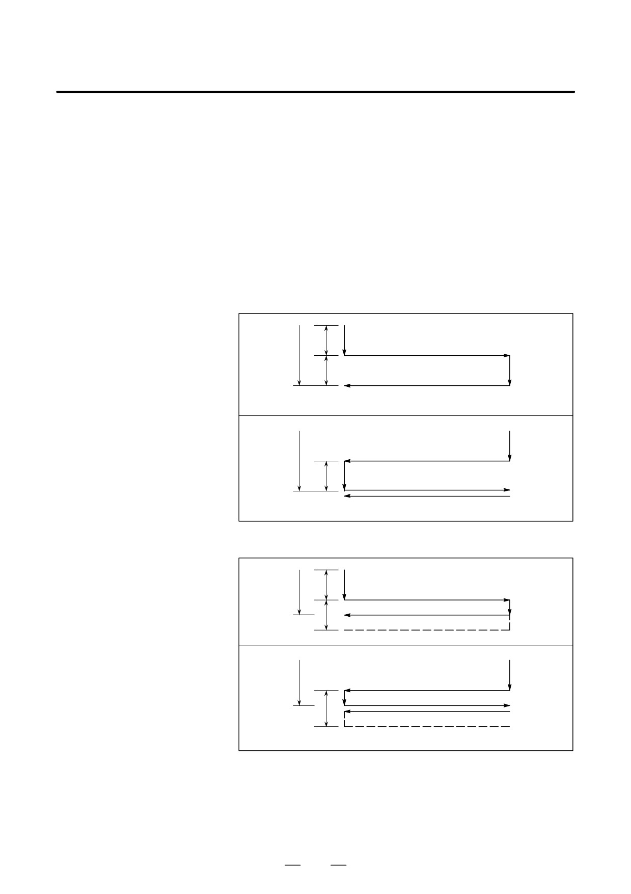
The plunge grinding cycle consists of six operation sequences.
Operations (1) to (6) are repeated until the depth reaches the total depth
of cut specified at address K. In the single block stop mode, operations
(1) to (6) are performed every cycle start.
D Grinding wheel cutting
(1) Cutting is performed along the Y-axis in cutting feed mode for the
amount specified by I (depth of cut 1). The feedrate is specified by R.
D Dwell
(2) Dwell is performed for the time specified by P.
D Grinding
(3) Cutting feed is performed for the amount specified by X (or Z). The
feedrate is specified by F.
D Grinding wheel cutting
(4) Cutting is performed along the Y-axis in cutting feed mode for the
amount specified by J (depth of cut 2). The feedrate is specified by R.
D Dwell
(5) Dwell is performed for the time specified by P.
D Grinding
(6) Feeding is performed in the reverse direction for the amount specified
(return direction)
by X (or Z) at a feedrate specified by F.
187
13. FUNCTIONS TO SIMPLIFY
PROGRAMMING
PROGRAMMING
B-64124EN/01
Limitations
D X(Z), I, J, K
X, (Z), I, J, and K must all be specified in incremental mode.
D Clear
I, J, X, and Z in canned cycles are modal data common to G75, G77, G78,
and G79. They remain valid until new data is specified. They are cleared
when a group 00 G code other than G04 or a group 01 G code other than
G75, G77, G78, and G79 is specified.
D Operation performed
When the total depth of cut is reached during cutting using I or J, the
when the total depth of
subsequent operation sequences (up to
) are executed, then the cycle
cut is reached
terminates. In this case, no further cutting is performed after the total
depth of cut is reached.
D Chart of operation in which the total depth of cut is reached by cutting
specified by I and J:
I
K
J
K
I
D Chart of operation in which the total depth of cut is reached during
cutting specified by I and J:
I
K
J
K
I
188
13. FUNCTIONS TO SIMPLIFY
B-64124EN/01
PROGRAMMING
PROGRAMMING
13.3.2
A direct constant-dimension plunge grinding cycle is performed.
Direct
Constant-Dimension
Plunge Grinding Cycle
(G77)
Format
G77 I_ J_ K_ X(Z)_ R_ F_ P_ L_ ;
I_ : Depth-of-cut 1 (A sign in the command specifies the direction
of cutting.)
J_
: Depth-of-cut 2 (A sign in the command specifies the direction
of cutting.)
K_ : Total depth of cut (A sign in the command specifies the direction
of cutting.)
X(Z)_ : Range of grinding (A sign in the command specifies the direction
of grinding.)
R_ : Feedrate for I and J
F_ : Feedrate for X (Z)
P_ : Dwell time
L_
: Grinding-wheel wear compensation (Only for continuous
dressing)
G77
Y
X(Z)
(R)
I
(F)
J
P
(R)
(F)
P
X(Z)
Explanations
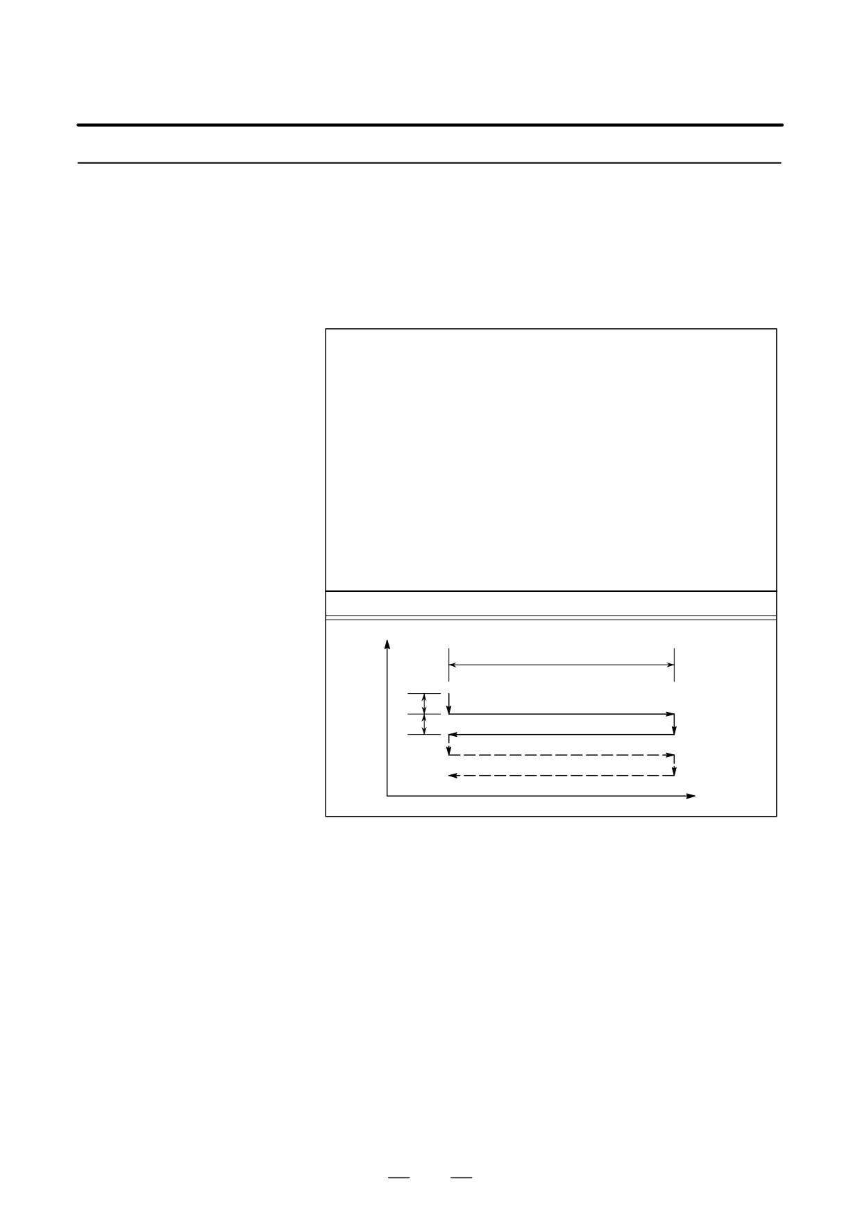
The constant-dimension plunge grinding cycle consists of six operation
sequences. Operations
to
are repeated until the depth reaches the
total depth of cut specified at address K.
D Grinding wheel cutting
Cutting is performed along the Y-axis in cutting feed mode for the
amount specified by I (depth of cut 1). The feedrate is specified by R.
D Dwell
Dwell is performed for the time specified by P.
D Grinding
Cutting feed is performed for the amount specified by X (or Z). The
feedrate is specified by F.
D Grinding wheel cutting
Cutting is performed along the Y-axis in cutting feed mode for the
amount specified by J (depth of cut 2). The feedrate is specified by R.
D Dwell
Dwell is performed for the time specified by P.
D Grinding
Feeding is performed in the reverse direction for the amount specified
(return direction)
by X (or Z) at a feedrate specified by F.
189
13. FUNCTIONS TO SIMPLIFY
PROGRAMMING
PROGRAMMING
B-64124EN/01
D Skip signal
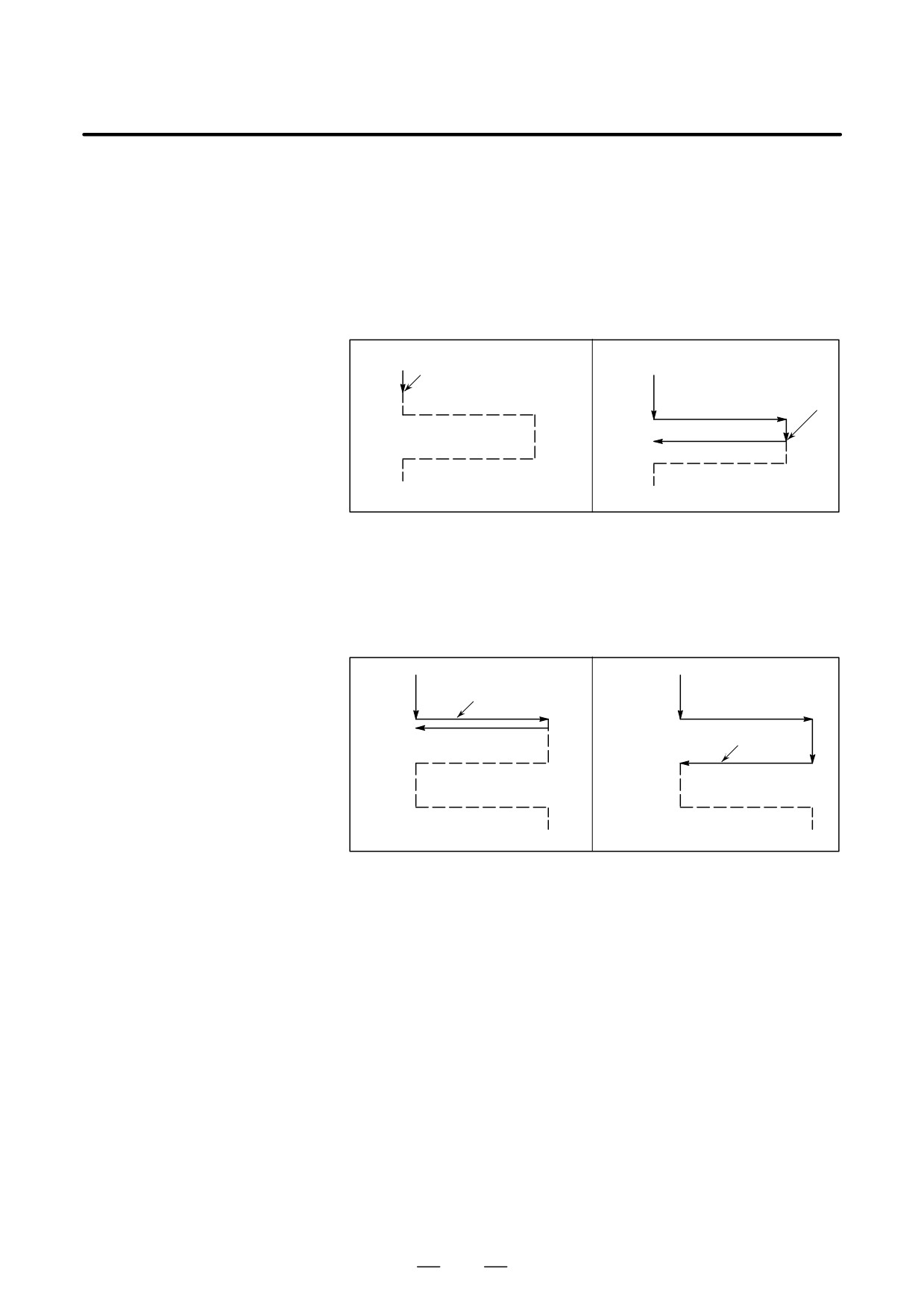
When the cycle is performed using G77, a skip signal can be input to
terminate the cycle. When a skip signal is input, the current operation
sequence is interrupted or completed, then the cycle is terminated.
The following shows how the system operates when the skip signal is
input during each operation sequence.
D When the skip signal is input during operation sequence 1 or 4 (cutting
feed specified by I or J), cutting is stopped immediately and the tool
returns to the X (Z) coordinate at which the cycle started.
Skip Signal
(End)
Skip Signal
(End)
D When the skip signal is input during operation sequence 2 or 5 (dwell),
dwell is stopped immediately and the tool returns to the X (Z)
coordinate at which the cycle started.
D When the skip signal is input during operation sequence 3 or 6
(movement), the tool returns to the X (Z) coordinate at which the cycle
started after the movement specified by X (Z) is completed.
Skip Signal
(End)
Skip Signal
(End)
Limitations
D X(Z), I, J, K
X, (Z), I, J, and K must all be specified in incremental mode.
D Clear
I, J, X, and Z in canned cycles are modal data common to G75, G77, G78,
and G79. They remain valid until new data is specified. They are cleared
when a group 00 G code other than G04 or a group 01 G code other than
G75, G77, G78, and G79 is specified.
190
13. FUNCTIONS TO SIMPLIFY
B-64124EN/01
PROGRAMMING
PROGRAMMING
13.3.3
A continuous-feed surface grinding cycle is performed.
Continuous-Feed
Surface Grinding Cycle
(G78)
Format
G78 I_ (J_) K_ X_ F_ P_ L_ ;
I_
: Depth-of-cut 1
(A sign in the command specifies the direction of cutting.)
J_
: Depth-of-cut 2
(A sign in the command specifies the direction of cutting.)
K_
: Total depth of cut
(A sign in the command specifies the direction of cutting.)
X(Z)_ : Range of grinding
(A sign in the command specifies the direction of grinding.)
R_
: Feedrate for I and J
F_
: Feed rate
P_
: Dwell time
L_
: Grinding-wheel wear compensation
(Only for continuous dressing)
G78
Z
X
P(Dwell)
(F)
I
I(J)
(F)
P(Dwell)
X
Explanations
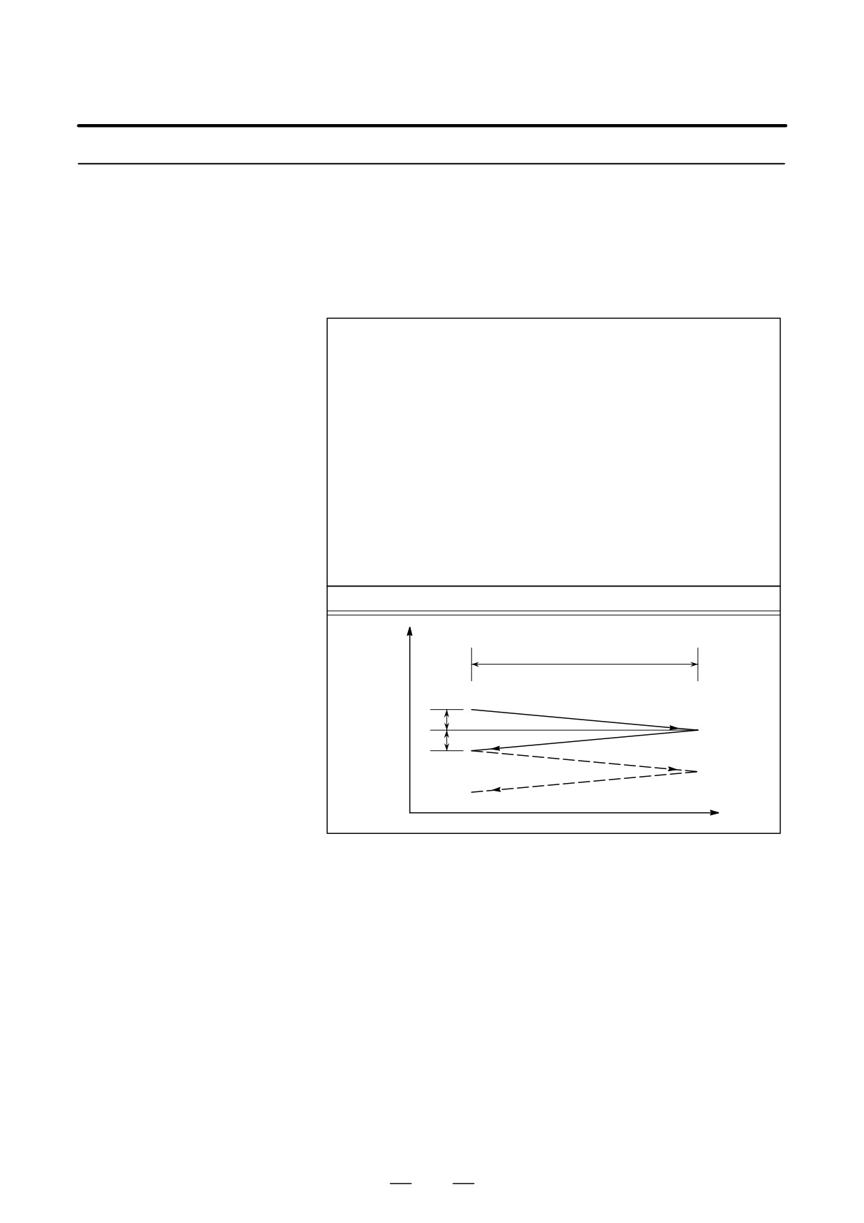
The continuous-feed surface grinding cycle consists of four operation
sequences. Operations
to
are repeated until the depth reaches
the total depth of cut specified in address K. In the single block stop mode,
operations
to
are performed every cycle start.
Dwell
Grinding
Dwell
Grinding (in reverse direction)
191
13. FUNCTIONS TO SIMPLIFY
PROGRAMMING
PROGRAMMING
B-64124EN/01
Restrictions
D J
When J is omitted, it is assumed to be 1. J is valid only in the block where
it is specified.
D I, J, K, X
X, (Z), I, J, and K must all be specified in incremental mode.
D Clear
I, J, X, and Z in canned cycles are modal data common to G75, G77, G78,
and G79. They remain valid until new data is specified. They are cleared
when a group 00 G code other than G04 or a group 01 G code other than
G75, G77, G78, and G79 is specified.
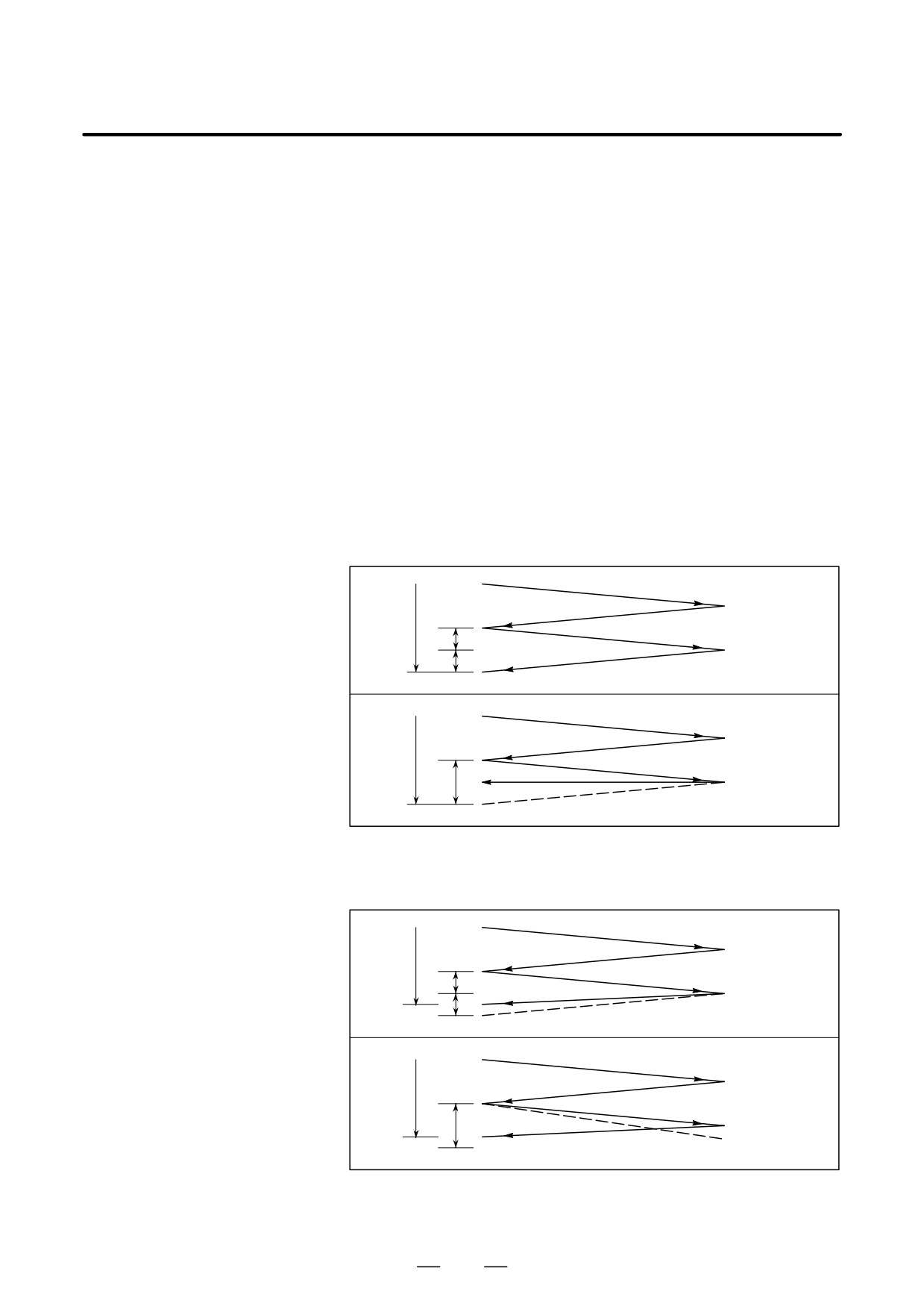
D Operation performed
When the total depth of cut is reached during cutting using I or J, the
when the total depth of
subsequent operation sequences (up to
) are executed, then the cycle
cut is reached
terminates. In this case, no further cutting is performed after the total
depth of cut is reached.
D Chart of operation in which the total depth of cut is reached by cutting
specified by I and J:
K
I
J
K
I
D Chart of operation in which the total depth of cut is reached during
cutting specified by I and J:
K
I
J
K
I
192