FANUC Series 0i-MC. OPERATOR’S MANUAL - page 2
B-64124EN/01
PROGRAMMING
1. GENERAL
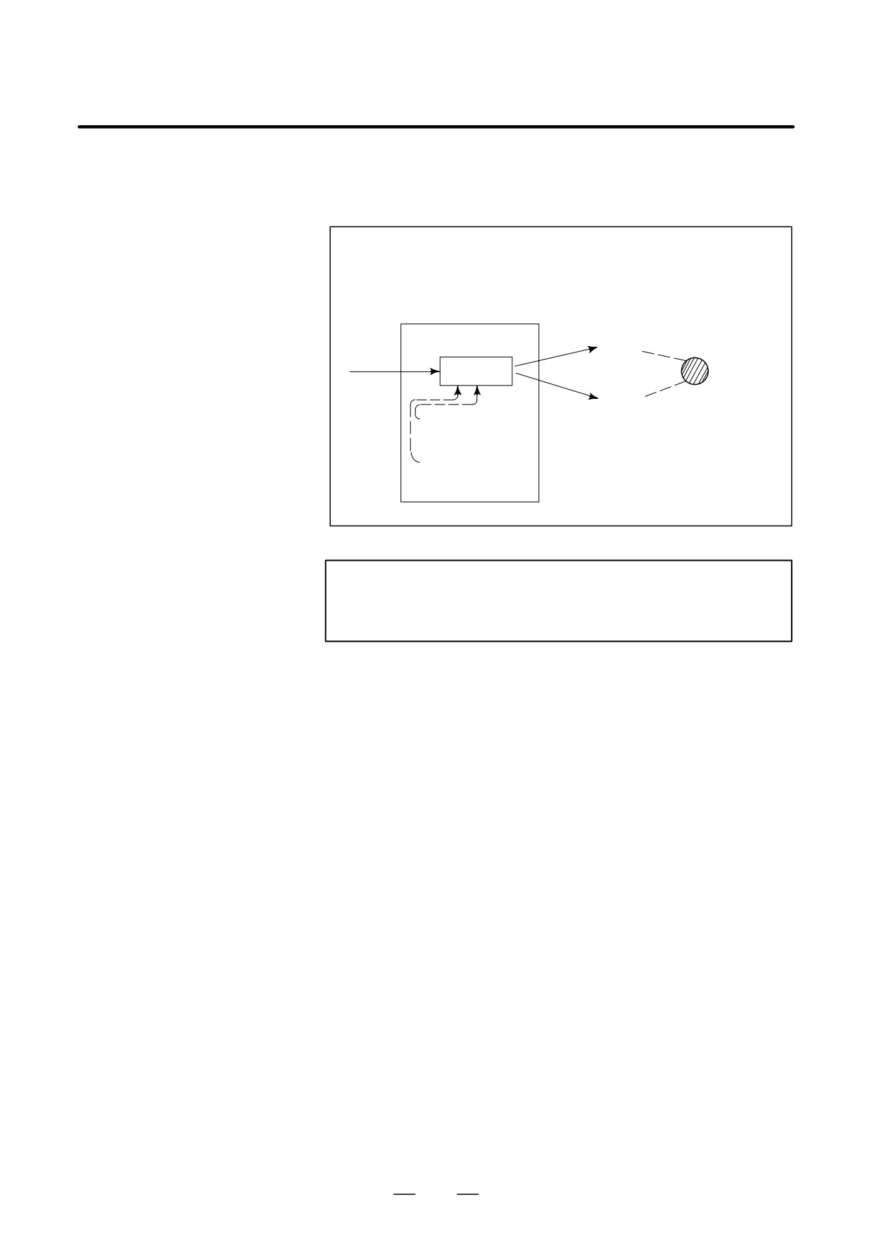
Symbols of the programmed commands G01, G02, ... are called the
preparatory function and specify the type of interpolation conducted in
the control unit.
(a) Movement along straight line
(b) Movement along arc
G01 Y_ _;
G03X--Y--R--;
X- -Y- - - -;
Control unit
X axis
Tool
Interpolation
move-
ment
Y axis
a)Movement
along straight
line
b)Movement
along arc
Fig. 1.1 (c) Interpolation function
NOTE
Some machines move tables instead of tools but this
manual assumes that tools are moved against workpieces.
13
1. GENERAL
PROGRAMMING
B-64124EN/01
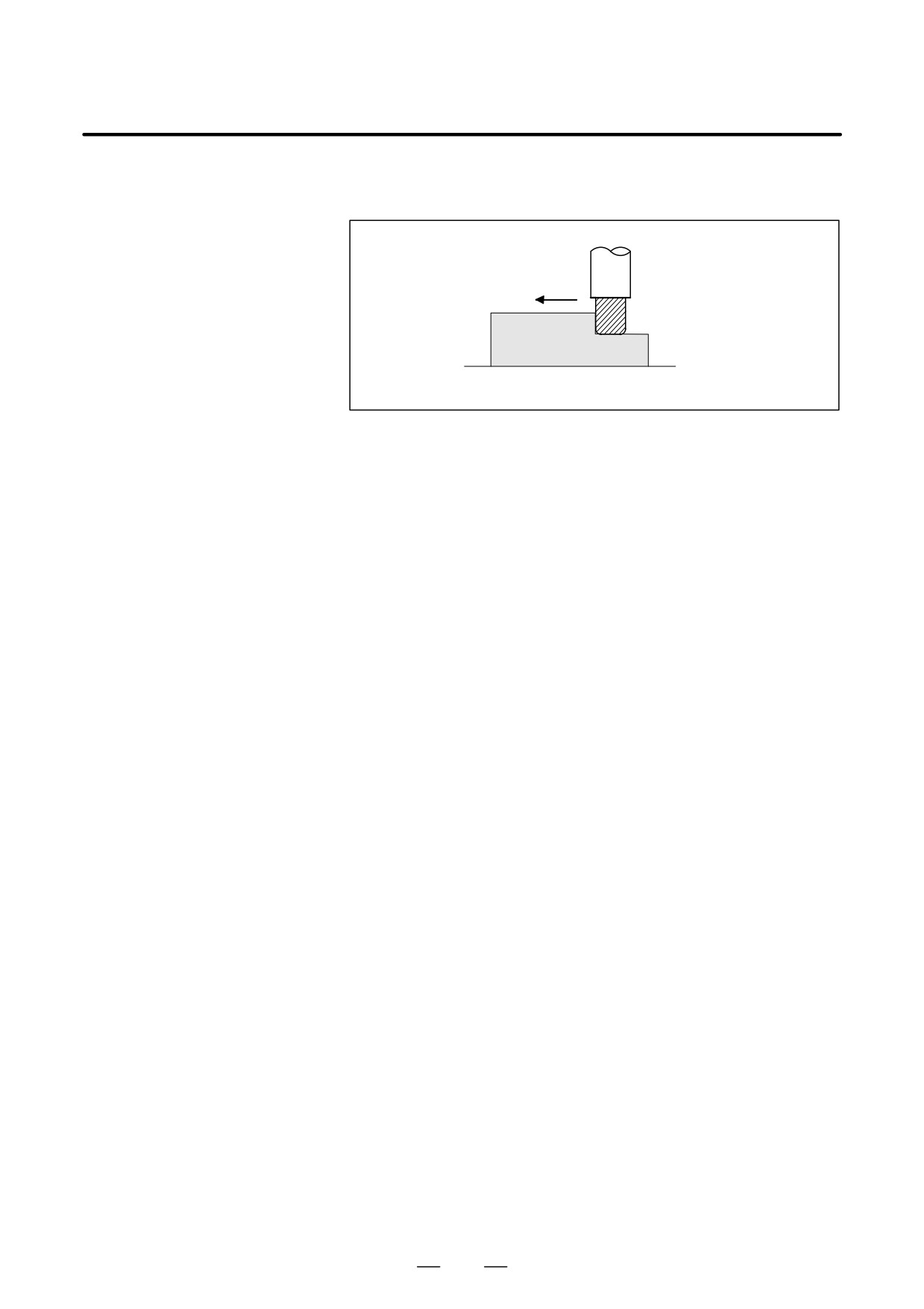
Movement of the tool at a specified speed for cutting a workpiece is called
1.2
the feed.
FEED-FEED
FUNCTION
mm/min
Tool
F
Workpiece
Table
Fig. 1.2 Feed function
Feedrates can be specified by using actual numerics. For example, to feed
the tool at a rate of 150 mm/min, specify the following in the program:
F150.0
The function of deciding the feed rate is called the feed function (See
II-5).
14
B-64124EN/01
PROGRAMMING
1. GENERAL
1.3
PART DRAWING AND
TOOL MOVEMENT
1.3.1
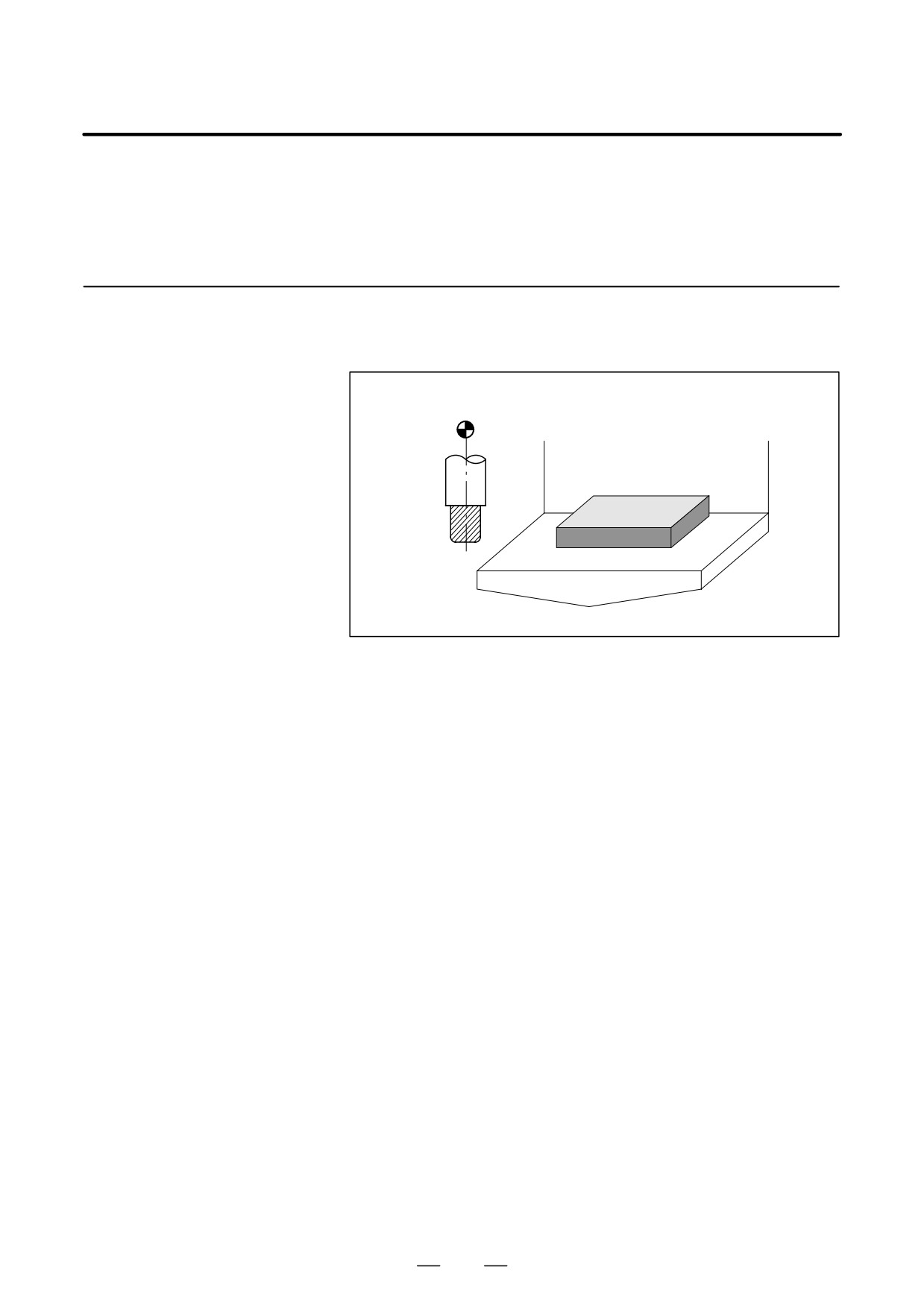
A CNC machine tool is provided with a fixed position. Normally, tool
change and programming of absolute zero point as described later are
Reference Position
performed at this position. This position is called the reference position.
(Machine-Specific
Position)
Reference position
Tool
Workpiece
Table
Fig. 1.3.1 Reference position
Explanations
The tool can be moved to the reference position in two ways:
(1) Manual reference position return (See III-3.1)
Reference position return is performed by manual button operation.
(2) Automatic reference position return (See II-6)
In general, manual reference position return is performed first after the
power is turned on. In order to move the tool to the reference position
for tool change thereafter, the function of automatic reference position
return is used.
15
1. GENERAL
PROGRAMMING
B-64124EN/01
1.3.2
Coordinate System on
Part Drawing and
Z
Coordinate System
Z
Specified by CNC -
Program
Y
Y
Coordinate System
X
X
Coordinate system
Part drawing
CNC
Command
Tool
Z
Y
Workpiece
X
Machine tool
Fig. 1.3.2 (a) Coordinate system
Explanations
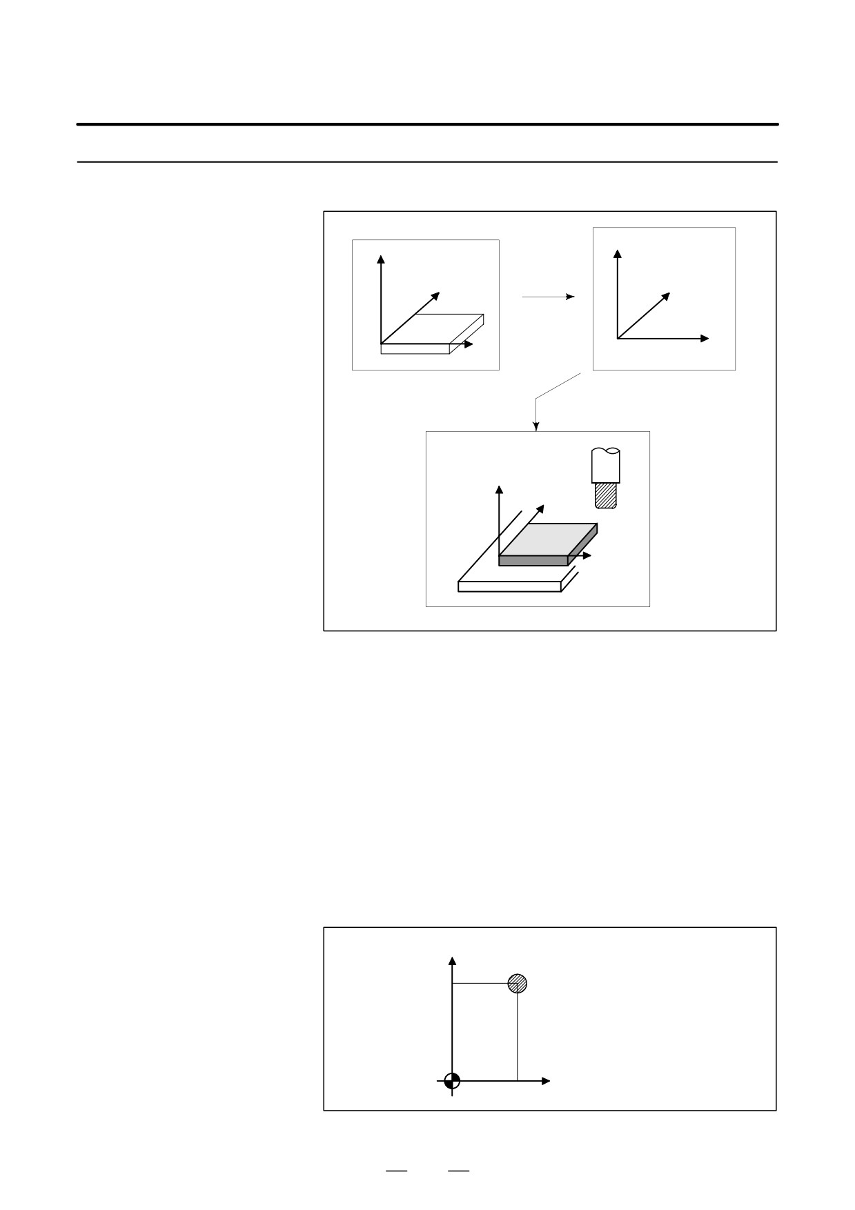
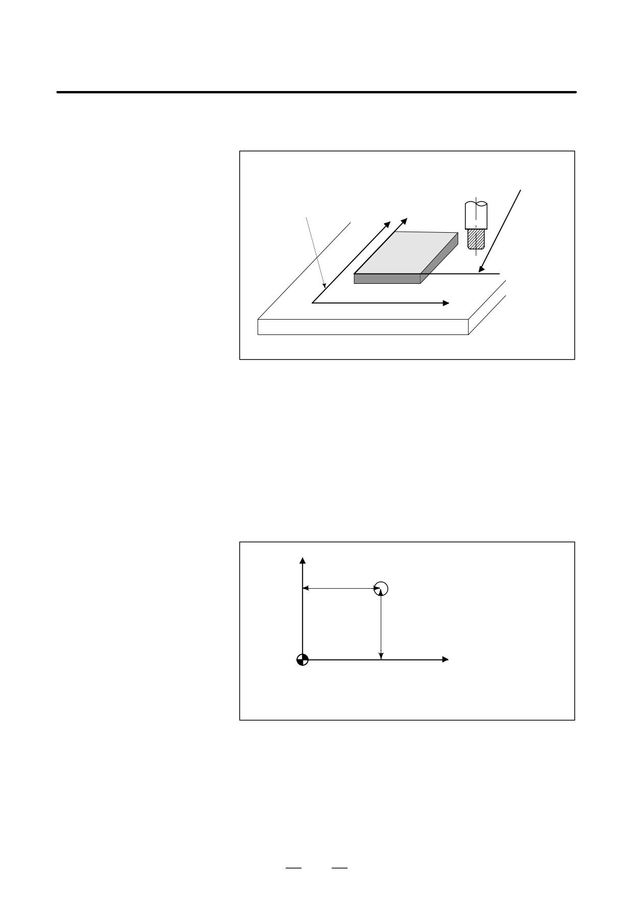
D Coordinate system
The following two coordinate systems are specified at different locations:
(See II-7)
(1) Coordinate system on part drawing
The coordinate system is written on the part drawing. As the program
data, the coordinate values on this coordinate system are used.
(2) Coordinate system specified by the CNC
The coordinate system is prepared on the actual machine tool table.
This can be achieved by programming the distance from the current
position of the tool to the zero point of the coordinate system to be set.
Y
230
Present tool position
300
Distance to the zero point of a coor-
Program
dinate system to be set
zero point
X
Fig. 1.3.2 (b) Coordinate system specified by the CNC
16
B-64124EN/01
PROGRAMMING
1. GENERAL
The positional relation between these two coordinate systems is
determined when a workpiece is set on the table.
Coordinate system on
part drawing established
on the workpiece
Coordinate system spe-
cified by the CNC estab-
lished on the table
Y Y
Workpiece
X
X
Table
Fig. 1.3.2 (c) Coordinate system specified by CNC and coordinate
systemon part drawing
The tool moves on the coordinate system specified by the CNC in
accordance with the command program generated with respect to the
coordinate system on the part drawing, and cuts a workpiece into a shape
on the drawing.
Therefore, in order to correctly cut the workpiece as specified on the
drawing, the two coordinate systems must be set at the same position.
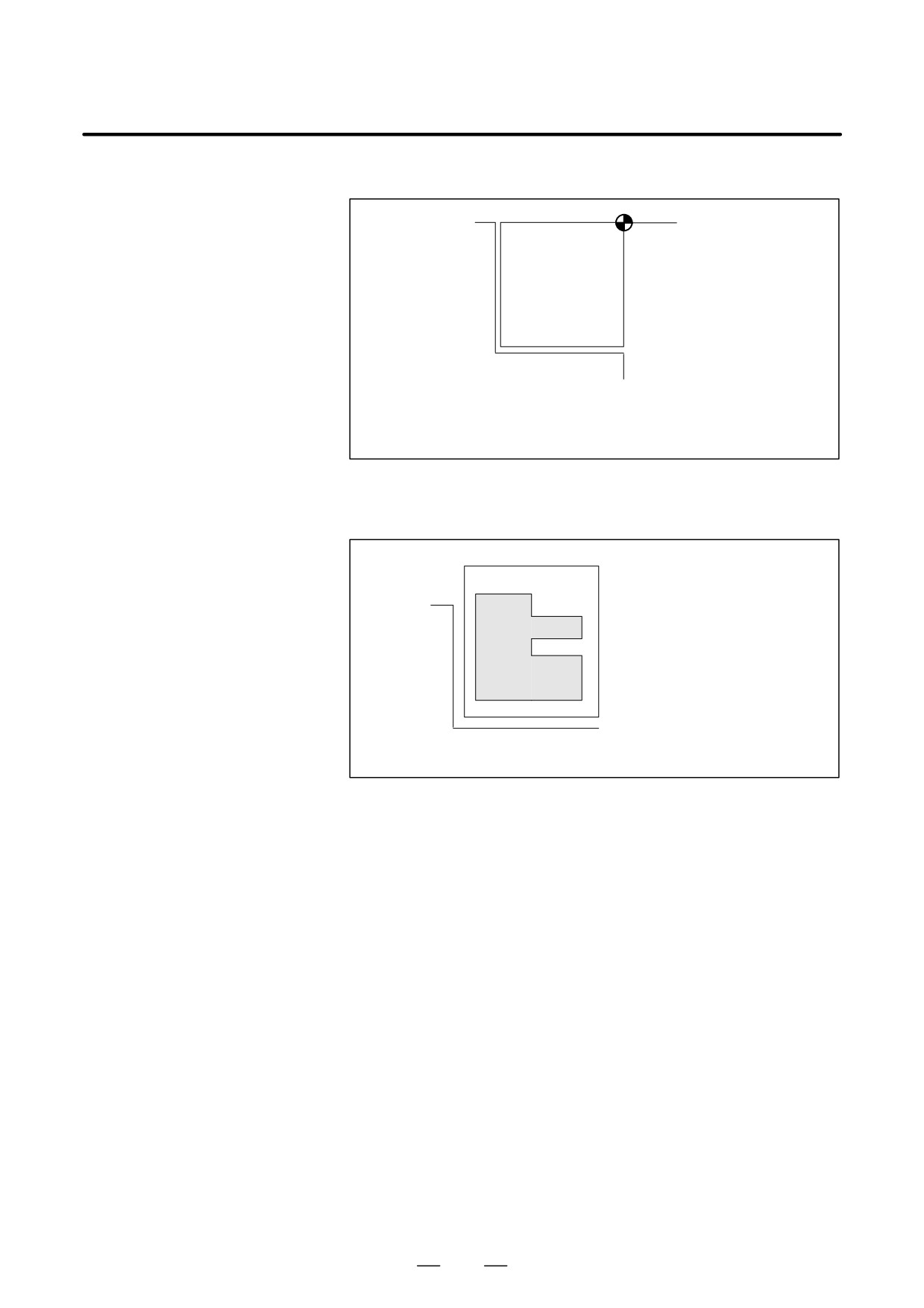
D Methods of setting the
To set the two coordinate systems at the same position, simple methods
two coordinate systems
shall be used according to workpiece shape, the number of machinings.
in the same position
(1) Using a standard plane and point of the workpiece.
Y
Workpiece’s
Fixed distance
standard point
Fixed distance
Program
zero point
X
Bring the tool center to the workpiece standard point.
And set the coordinate system specified by CNC at this position.
17
1. GENERAL
PROGRAMMING
B-64124EN/01
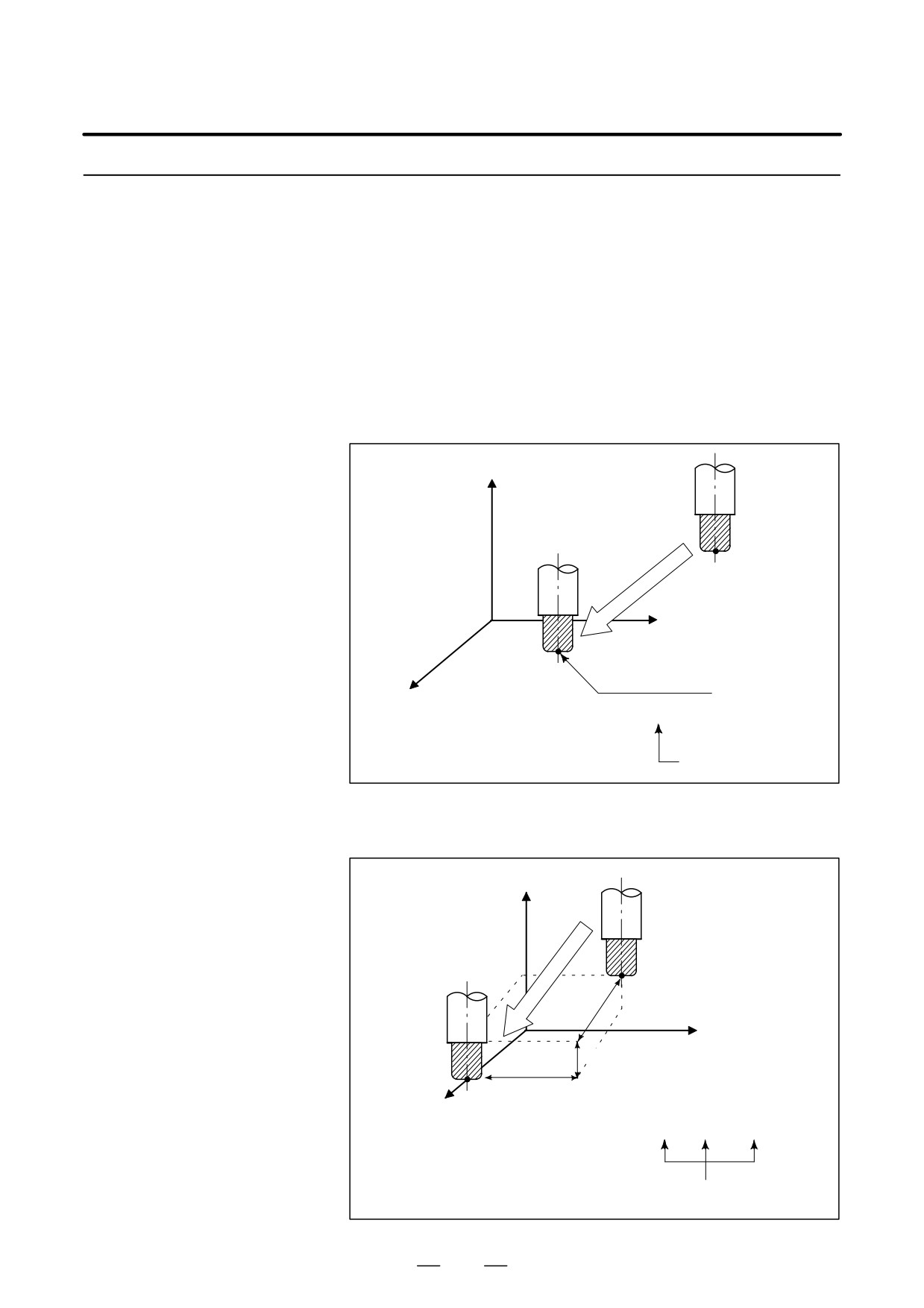
(2) Mounting a workpiece directly against the jig
Program zero point
Jig
Meet the tool center to the reference position. And set the coordinate system
specified by CNC at this position. (Jig shall be mounted on the predetermined
point from the reference position.)
(3) Mounting a workpiece on a pallet, then mounting the workpiece and
pallet on the jig
ÂÂÂÂÂÂÂ
ÂPalletÂÂÂÂÂ
 ÂÂÂÂ
Â
ÂÂ
Jig
Â
ÂÂ
Workpiece
Â
ÂÂ
ÂÂÂÂÂÂÂ
ÂÂÂÂÂÂÂ
(Jig and coordinate system shall be specified by the same as (2)).
18
B-64124EN/01
PROGRAMMING
1. GENERAL
1.3.3
How to Indicate
Command Dimensions
for Moving the Tool -
Absolute, Incremental
Commands
Explanations
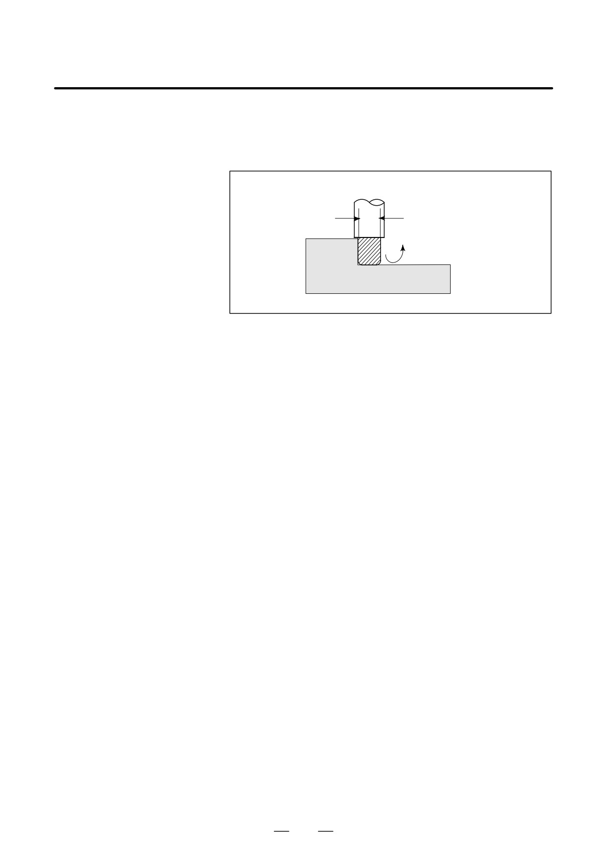
Command for moving the tool can be indicated by absolute command or
incremental command (See II-8.1).
D Absolute command
The tool moves to a point at “the distance from zero point of the
coordinate system” that is to the position of the coordinate values.
Z
Tool
A
Y
X
B(10.0,30.0,20.0)
Command specifying movement from G90 X10.0 Y30.0 Z20.0 ;
point A to point B
Coordinates of point B
D Incremental command
Specify the distance from the previous tool position to the next tool
position.
Z
Tool
A
X=40.0
Y
Z=-10.0
B
X
Y=-30.0
Command specifying movement from
G91 X40.0 Y-30.0 Z-10.0 ;
point A to point B
Distance and direction for
movement along each axis
19
1. GENERAL
PROGRAMMING
B-64124EN/01
1.4
The speed of the tool with respect to the workpiece when the workpiece
is cut is called the cutting speed.
CUTTING SPEED -
As for the CNC, the cutting speed can be specified by the spindle speed
SPINDLE SPEED
in min-1 unit.
FUNCTION
Tool
Tool diameter
Spindle speed N
min-1
f D mm
V: Cutting speed
m/min
Workpiece
Examples
<When a workpiece should be machined with a tool 100 mm in
diameter at a cutting speed of 80 m/min. >
The spindle speed is approximately 250 min-1, which is obtained from
N=1000v/πD. Hence the following command is required:
S250;
Commands related to the spindle speed are called the spindle speed
function (See II-9) .
20
B-64124EN/01
PROGRAMMING
1. GENERAL
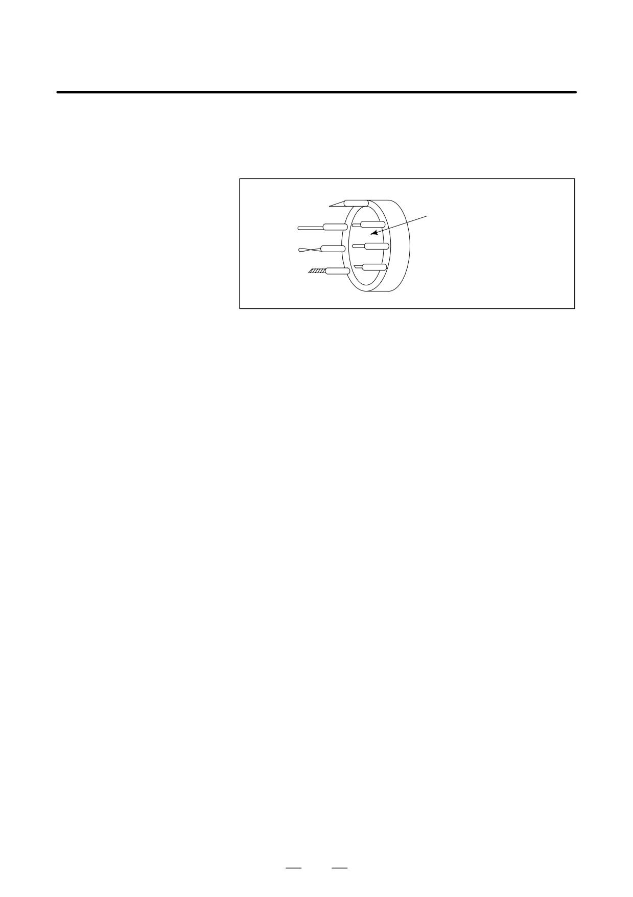
1.5
When drilling, tapping, boring, milling or the like, is performed, it is
necessary to select a suitable tool. When a number is assigned to each tool
SELECTION OF TOOL
and the number is specified in the program, the corresponding tool is
USED FOR VARIOUS
selected.
MACHINING - TOOL
FUNCTION
Tool number
01
ATC magazine
02
Examples
<When No.01 is assigned to a drilling tool>
When the tool is stored at location 01 in the ATC magazine, the tool
can be selected by specifying T01. This is called the tool function (See
II-10).
21
1. GENERAL
PROGRAMMING
B-64124EN/01
1.6
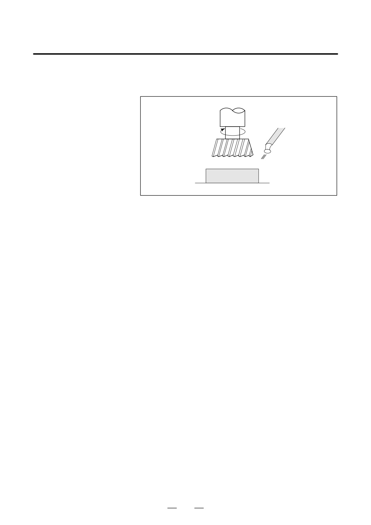
When machining is actually started, it is necessary to rotate the spindle,
and feed coolant. For this purpose, on-off operations of spindle motor and
COMMAND FOR
coolant valve should be controlled.
MACHINE
OPERATIONS -
MISCELLANEOUS
Tool
FUNCTION
Coolant
Workpiece
The function of specifying the on-off operations of the components of the
machine is called the miscellaneous function. In general, the function is
specified by an M code (See II-11).
For example, when M03 is specified, the spindle is rotated clockwise at
the specified spindle speed.
22
B-64124EN/01
PROGRAMMING
1. GENERAL
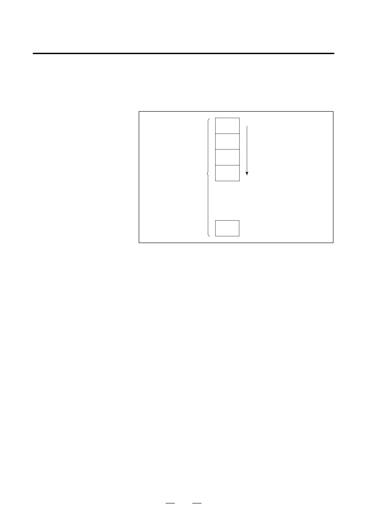
A group of commands given to the CNC for operating the machine is
1.7
called the program. By specifying the commands, the tool is moved along
PROGRAM
a straight line or an arc, or the spindle motor is turned on and off.
CONFIGURATION
In the program, specify the commands in the sequence of actual tool
movements.
Block
Block
Tool movement sequence
Block
Program
Block
⋅
⋅
⋅
⋅
Block
Fig. 1.7 (a) Program configuration
A group of commands at each step of the sequence is called the block.
The program consists of a group of blocks for a series of machining. The
number for discriminating each block is called the sequence number, and
the number for discriminating each program is called the program
number (See II-12).
23
1. GENERAL
PROGRAMMING
B-64124EN/01
Explanations
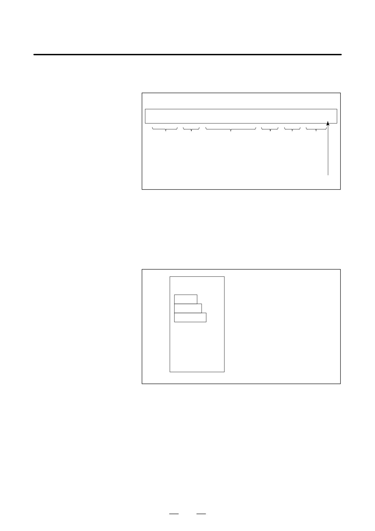
The block and the program have the following configurations.
D Block
1 block
N ffff G ff Xff.f Yfff.f M ff S ff T ff ;
Sequence Preparatory Dimension word Miscel-
Spindle Tool
number function
laneous
function func-
function
tion
End of
block
Fig. 1.7 (b) Block configuration
A block starts with a sequence number to identify the block and ends with
an end-of-block code.
This manual indicates the end-of-block code by ; (LF in the ISO code and
CR in the EIA code).
The contents of the dimension word depend on the preparatory function.
In this manual, the portion of the dimension word may be represent as IP_.
D Program
;
Offff;
Program number
Block
Block
Block
⋅
⋅
⋅
⋅
⋅
⋅
M30 ;
End of program
Fig. 1.7 (c) Program configuration
Normally, a program number is specified after the end-of-block (;) code
at the beginning of the program, and a program end code (M02 or M30)
is specified at the end of the program.
24
B-64124EN/01
PROGRAMMING
1. GENERAL
D Main program and
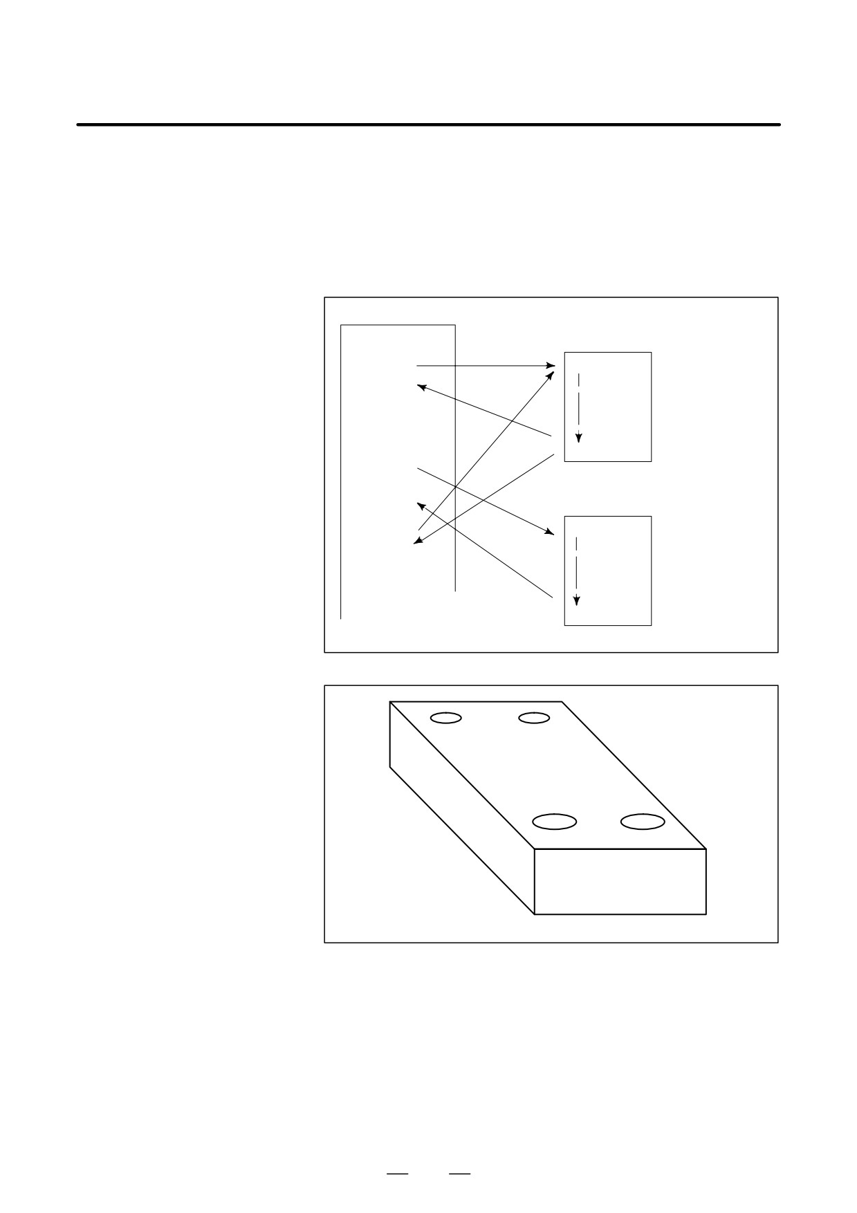
When machining of the same pattern appears at many portions of a
subprogram
program, a program for the pattern is created. This is called the
subprogram. On the other hand, the original program is called the main
program. When a subprogram execution command appears during
execution of the main program, commands of the subprogram are
executed. When execution of the subprogram is finished, the sequence
returns to the main program.
Main program
⋅
Subprogram #1
⋅
M98P1001
O1001
Program for
hole #1
⋅
⋅
⋅
M99
M98P1002
⋅
⋅
Subprogram #2
O1002
Program for
M98P1001⋅
hole #2
⋅
⋅
⋅
M99
Hole #1
Hole #1
Hole #2
Hole #2
25
1. GENERAL
PROGRAMMING
B-64124EN/01
1.8
TOOL FIGURE AND
TOOL MOTION BY
PROGRAM
Explanations
D Machining using the end
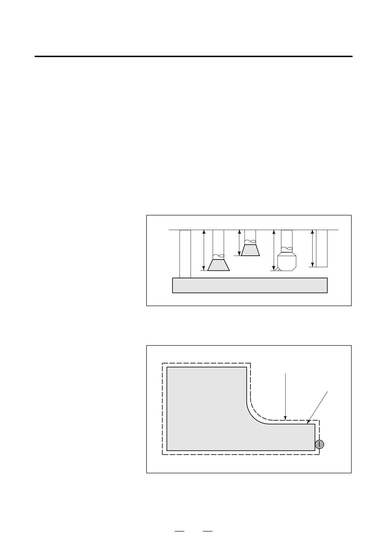
Usually, several tools are used for machining one workpiece. The tools
of cutter - Tool length
have different tool length. It is very troublesome to change the program
compensation function
in accordance with the tools.
(See II-14.1)
Therefore, the length of each tool used should be measured in advance.
By setting the difference between the length of the standard tool and the
length of each tool in the CNC (data display and setting : see III-11),
machining can be performed without altering the program even when the
tool is changed. This function is called tool length compensation.
ÇÇÇ
ÂÂ
ÇÇÇ
ÂÂ
H1
H2
H3
H4
StandardÇÇ
ÂÂ
tool
ÇÇÇ
ÂÂ
ÇÇÇ
ÂÂ
ÇÇÇ
Workpiece
D Machining using the side
Because a cutter has a radius, the center of the cutter path goes around the
of cutter - Cutter
workpiece with the cutter radius deviated.
compensation function
(See II-14.4,14.5,14.6)
Cutter path using cutter
compensation
Machined part
figure
Workpiece
Cutter
If radius of cutters are stored in the CNC (Data Display and Setting : see
III-11), the tool can be moved by cutter radius apart from the machining
part figure. This function is called cutter compensation.
26
B-64124EN/01
PROGRAMMING
1. GENERAL
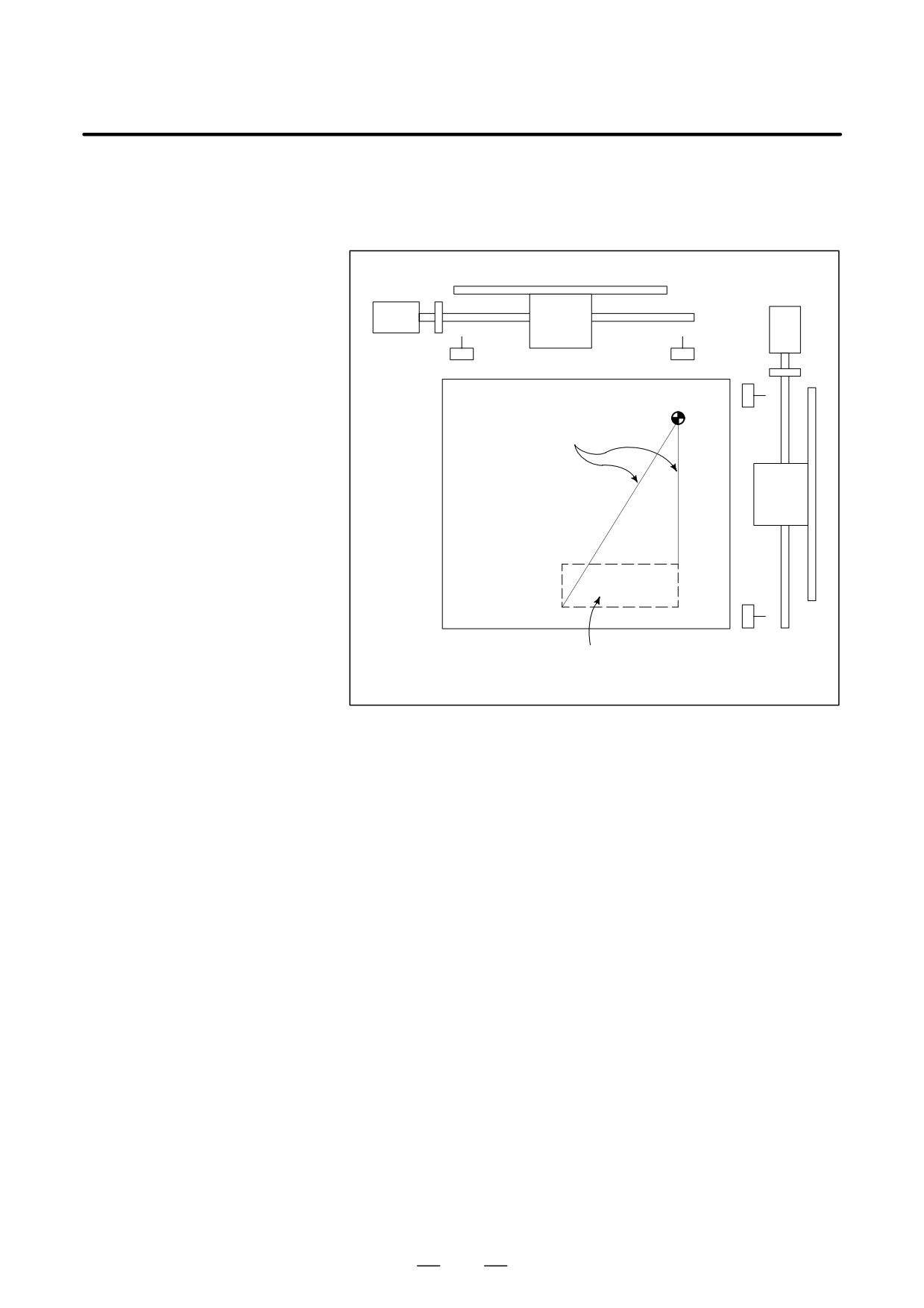
Limit switches are installed at the ends of each axis on the machine to
1.9
prevent tools from moving beyond the ends. The range in which tools can
TOOL MOVEMENT
move is called the stroke.
RANGE - STROKE
Table
Motor
Limit switch
Machine zero point
Specify these distances.
ÇÇÇÇÇÇ
ÇÇÇÇÇÇ
ÇÇÇÇÇÇ
Tools cannot enter this area. The area is specified by data in memory or
a program.
Besides strokes defined with limit switches, the operator can define an
area which the tool cannot enter using a program or data in memory. This
function is called stroke check (see III-6.3).
27
2. CONTROLLED AXES
PROGRAMMING
B-64124EN/01
CONTROLLED AXES
2
28

B-64124EN/01
PROGRAMMING
2. CONTROLLED AXES
2.1
CONTROLLED AXES
Item
0i-MC
No. of basic controlled axes
3 axes
Controlled axes expansion (total)
Max. 4 axes (included in Cs axis)
Basic simultaneously controlled axes
3 axes
Simultaneously controlled axes
Max. 4 axes
expansion (total)
NOTE
The number of simultaneously controllable axes for manual
operation jog feed, manual reference position return, or
manual rapid traverse) is 1 or 3 (1 when bit 0 (JAX) of
parameter 1002 is set to 0 and 3 when it is set to 1).
2.2
The names of three basic axes are always X, Y, and Z. The name of an
additional axis can be set to A, B, C, U, V, or W by using parameter 1020.
AXIS NAME
Parameter No. 1020 is used to determine the name of each axis.
Limitations
D Default axis name
When this parameter is set to 0 or a character other than the valid
characters is specified, an axis name from 1 to 4 is assigned by default.
When a default axis name (1 to 4) is used, operation in the MEM mode
and MDI mode is disabled.
D Duplicate axis names
If a duplicate axis name is specified in the parameter, operation is enabled
only for the axis specified first.
29
2. CONTROLLED AXES
PROGRAMMING
B-64124EN/01
2.3
The increment system consists of the least input increment (for input) and
least command increment (for output). The least input increment is the
INCREMENT SYSTEM
least increment for programming the travel distance. The least command
increment is the least increment for moving the tool on the machine. Both
increments are represented in mm, inches, or deg.
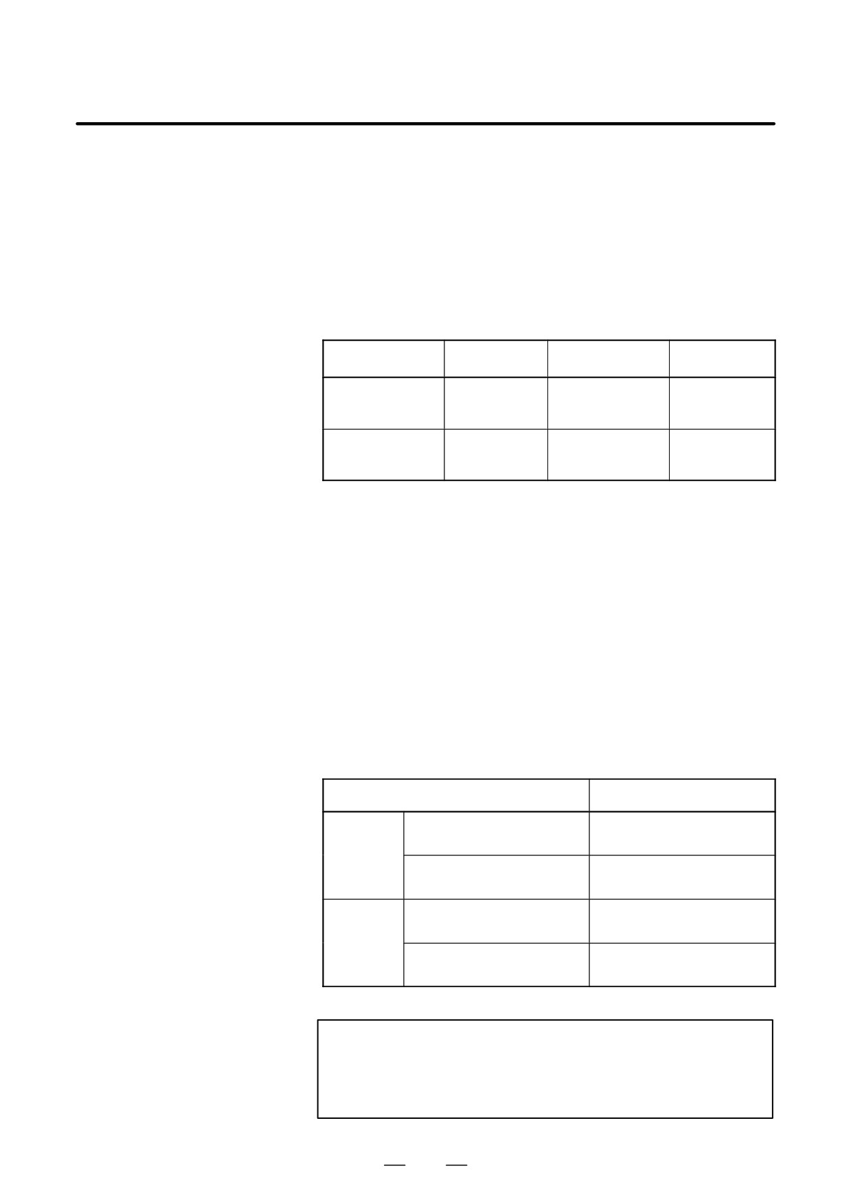
Set bit 1 (ISC) of parameter No. 1004 to select which increment system
to use. The setting of bit 1 (ISC) of parameter No. 1004 is applied to all
the axes. For example, when IS-C is selected, the increment system for
all the axes is IS-C.
Name of
Least input
Least command
Maximum
increment system
increment
increment
stroke
0.001mm
0.001mm
99999.999mm
IS-B
0.0001inch
0.0001inch
9999.9999inch
0.001deg
0.001deg
99999.999deg
0.0001mm
0.0001mm
9999.9999mm
IS-C
0.00001inch
0.00001inch
999.99999inch
0.0001deg
0.0001deg
9999.9999deg
The least command increment is either metric or inch depending on the
machine tool. Set metric or inch to the parameter INM (No.100#0).
For selection between metric and inch for the least input increment, G
code (G20 or G21) or a setting parameter selects it.
Combined use of the inch system and the metric system is not allowed.
There are functions that cannot be used between axes with different unit
systems (circular interpolation, cutter compensation, etc.). For the
increment system, see the machine tool builder’s manual.
2.4
Maximum stroke = Least command increment
99999999
See table 2.4 Incremen System.
MAXIMUM STROKE
Table 2.4 Maximum strokes
Increment system
Maximum stroke
Metric machine system
± 99999.999 mm
± 99999.999 deg
IS–B
Inch machine system
± 9999.9999 inch
± 99999.999 deg
Metric machine system
± 9999.9999 mm
± 9999.9999 deg
IS–C
Inch machine system
± 999.99999 inch
± 9999.9999 deg
NOTE
1
A command exceeding the maximum stroke cannot be
specified.
2
The actual stroke depends on the machine tool.
30
3. PREPARATORY FUNCTION
B-64124EN/01
PROGRAMMING
(G FUNCTION)
PREPARATORY FUNCTION (G FUNCTION)
3
A number following address G determines the meaning of the command
for the concerned block.
G codes are divided into the following two types.
Type
Meaning
One-shot G code
The G code is effective only in the block in which it is
specified.
Modal G code
The G code is effective until another G code of the
same group is specified.
(Example )
G01 and G00 are modal G codes in group 01.
G01X ;
Z;
G01 is effective in this range.
X;
G00Z ;
31
3. PREPARATORY FUNCTION
(G FUNCTION)
PROGRAMMING
B-64124EN/01
Explanations
1. When the clear state (bit 6 (CLR) of parameter No. 3402) is set at
power-up or reset, the modal G codes are placed in the states
described below.
(1) The modal G codes are placed in the states marked with
as
indicated in Table 3.
(2) G20 and G21 remain unchanged when the clear state is set at
power-up or reset.
(3) Which status G22 or G23 at power on is set by parameter G23 (No.
3402#7). However, G22 and G23 remain unchanged when the
clear state is set at reset.
(4) The user can select G00 or G01 by setting bit 0 (G01) of parameter
No. 3402.
(5) The user can select G90 or G91 by setting bit 3 (G91) of parameter
No. 3402.
(6) The user can select G17, G18, or G19 by setting bit 1 (parameterG18)
and bit 2 (parameter G19) of parameter No. 3402.
2.G codes other than G10 and G11 are one-shot G codes.
3.When a G code not listed in the G code list is specified, or a G code
that has no corresponding option is specified, P/S alarm No. 010 is
output.
4.Multiple G codes can be specified in the same block if each G code
belongs to a different group. If multiple G codes that belong to the
same group are specified in the same block, only the last G code
specified is valid.
5.If a G code belonging to group 01 is specified in a canned cycle, the
canned cycle is cancelled. This means that the same state set by
specifying G80 is set. Note that the G codes in group 01 are not
affected by a G code specifying a canned cycle.
6.G codes are indicated by group.
7.The group of G60 is switched according to the setting of the MDL bit
(bit 0 of parameter 5431). (When the MDL bit is set to 0, the 00 group
is selected. When the MDL bit is set to 1, the 01 group is selected.)
32
3. PREPARATORY FUNCTION
B-64124EN/01
PROGRAMMING
(G FUNCTION)
Table 3 G code list (1/3)
G code
Group
Function
G00
Positioning
G01
Linear interpolation
01
G02
Circular interpolation/Helical interpolation CW
G03
Circular interpolation/Helical interpolation CCW
G04
Dwell, Exact stop
G05.1
AI advanced control/AI contour control
G07.1 (G107)
Cylindrical interpolation
G08
00
Advanced preview control
G09
Exact stop
G10
Programmable data input
G11
Programmable data input mode cancel
G15
Polar coordinates command cancel
17
G16
Polar coordinates command
G17
XpYp plane selection
Xp: X axis or its parallel axis
G18
02
ZpXp plane selection
Yp: Y axis or its parallel axis
G19
YpZp plane selection
Zp: Z axis or its parallel axis
G20
Input in inch
06
G21
Input in mm
G22
Stored stroke check function on
04
G23
Stored stroke check function off
G27
Reference position return check
G28
Return to reference position
G29
00
Return from reference position
G30
2nd, 3rd and 4th reference position return
G31
Skip function
G33
01
Thread cutting
G37
Automatic tool length measurment
00
G39
Corner offset circular interpolation
G40
Cutter compensation cancel/Three dimensional compensation cancel
G41
07
Cutter compensation left/Three dimensional compensation
G42
Cutter compensation right
G40.1 (G150)
Normal direction control cancel mode
G41.1 (G151)
19
Normal direction control left side on
G42.1 (G152)
Normal direction control right side on
G43
Tool length compensation + direction
08
G44
Tool length compensation - direction
G45
Tool offset increase
G46
Tool offset decrease
00
G47
Tool offset double increase
G48
Tool offset double decrease
33
3.
PREPARATORY FUNCTION
(G FUNCTION)
PROGRAMMING
B-64124EN/01
Table 3 G code list (2/3)
G code
Group
Function
G49
08
Tool length compensation cancel
G50
Scaling cancel
11
G51
Scaling
G50.1
Programmable mirror image cancel
22
G51.1
Programmable mirror image
G52
Local coordinate system setting
00
G53
Machine coordinate system selection
G54
Workpiece coordinate system 1 selection
G54.1
Additional workpiece coordinate system selection
G55
Workpiece coordinate system 2 selection
G56
14
Workpiece coordinate system 3 selection
G57
Workpiece coordinate system 4 selection
G58
Workpiece coordinate system 5 selection
G59
Workpiece coordinate system 6 selection
G60
00/01
Single direction positioning
G61
Exact stop mode
G62
Automatic corner override
15
G63
Tapping mode
G64
Cutting mode
G65
00
Macro call
G66
Macro modal call
12
G67
Macro modal call cancel
G68
Coordinate rotation/Three dimensional coordinate conversion
16
Coordinate rotation cancel/Three dimensional coordinate conversion
G69
cancel
G73
Peck drilling cycle
09
G74
Counter tapping cycle
G75
01
Plunge grinding cycle (for grinding machine)
G76
09
Fine boring cycle
G77
Direct constant-dimension plunge grinding cycle(for grinding machine)
G78
01
Continuous-feed surface grinding cycle(for grinding machine)
G79
Intermittent-feed surface grinding cycle(for grinding machine)
G80
Canned cycle cancel/external operation function cancel
G81
Drilling cycle, spot boring cycle or external operation function
G82
Drilling cycle or counter boring cycle
G83
Peck drilling cycle
G84
09
Tapping cycle
G85
Boring cycle
G86
Boring cycle
G87
Back boring cycle
G88
Boring cycle
G89
Boring cycle
34
3. PREPARATORY FUNCTION
B-64124EN/01
PROGRAMMING
(G FUNCTION)
Table 3 G code list (3/3)
G code
Group
Function
G90
Absolute command
03
G91
Increment command
G92
Setting for work coordinate system or clamp at maximum spindle speed
00
G92.1
Workpiece coordinate system preset
G94
Feed per minute
05
G95
Feed per rotation
G96
Constant surface speed control
13
G97
Constant surface speed control cancel
G98
Return to initial point in canned cycle
10
G99
Return to R point in canned cycle
G160
In-feed control function cancel (for grinding machine)
20
G161
In-feed control function (for grinding machine)
35
4. INTERPOLATION FUNCTIONS
PROGRAMMING
B-64124EN/01
INTERPOLATION FUNCTIONS
4
36
B-64124EN/01
PROGRAMMING
4. INTERPOLATION FUNCTIONS
4.1
The G00 command moves a tool to the position in the workpiece system
specified with an absolute or an incremental command at a rapid traverse
POSITIONING
rate.
(G00)
In the absolute command, coordinate value of the end point is
programmed.
In the incremental command the distance the tool moves is programmed.
Format
G00
IP
_;
IP: For an absolute command, the coordinates of an end
position, and for an incremental commnad, the distance
the tool moves.
Explanations
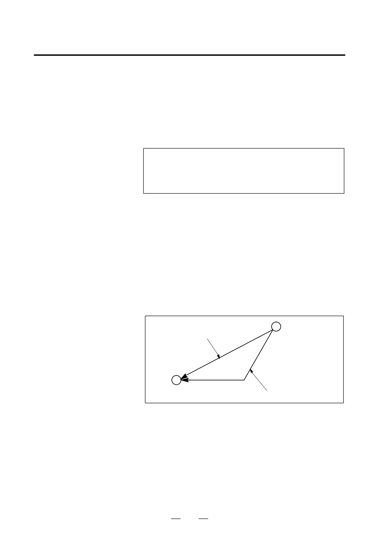
Either of the following tool paths can be selected according to bit 1 of
parameter LRP No. 1401.
D Nonlinear interpolation positioning
The tool is positioned with the rapid traverse rate for each axis
separately. The tool path is normally straight.
D Linear interpolation positioning
The tool path is the same as in linear interpolation (G01). The tool is
positioned within the shortest possible time at a speed that is not more
than the rapid traverse rate for each axis. However, the tool path is not
the same as in linear interpolation (G01).
Start position
Linear interpolation positioning
End position
Non linear interpolation positioning
The rapid traverse rate in G00 command is set to the parameter No. 1420
for each axis independently by the machine tool builder. In the
posiitoning mode actuated by G00, the tool is accelerated to a
predetermined speed at the start of a block and is decelerated at the end
of a block. Execution proceeds to the next block after confirming the
in-position.
“In-position ” means that the feed motor is within the specified range.
This range is determined by the machine tool builder by setting to
parameter (No. 1826).
In-position check for each block can be disabled by setting bit 5 (NCI)
of parameter No.1601 accordingly.
37
4. INTERPOLATION FUNCTIONS
PROGRAMMING
B-64124EN/01
Limitations
The rapid traverse rate cannot be specified in the address F.
Even if linear interpolation positioning is specified, nonlinear
interpolation positioning is used in the following cases. Therefore, be
careful to ensure that the tool does not foul the workpiece.
D G28 specifying positioning between the reference and intermediate
positions.
D G53
38
B-64124EN/01
PROGRAMMING
4. INTERPOLATION FUNCTIONS
4.2
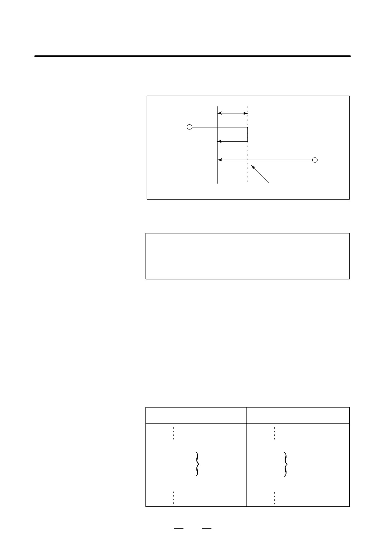
For accurate positioning without play of the machine (backlash), final
positioning from one direction is available.
SINGLE DIRECTION
POSITIONING (G60)
Overrun
Start position
Start position
Temporary stop
End position
Format
G60
_;
IP
IP : For an absolute command, the coordinates of an end
position, and for an incremental commnad, the distance
the tool moves.
Explanations
An overrun and a positioning direction are set by the parameter (No.
5440). Even when a commanded positioning direction coincides with
that set by the parameter, the tool stops once before the end point.
G60, which is an one-shot G-code, can be used as a modal G-code in
group 01 by setting 1 to the parameter (No. 5431 bit 0 MDL).
This setting can eliminate specifying a G60 command for every block.
Other specifications are the same as those for an one-shot G60 command.
When an one-shot G code is sepcified in the single direction positioning
mode, the one-shot G command is effective like G codes in group 01.
Examples
When one-shot
When modal
G60 commands are used.
G60 command is used.
G90;
G90G60;
Single direction
positioning mode start
G60
X0Y0;
X0Y0;
Single direction
Single direction
G60
X100;
X100;
positioning
positioning
G60
Y100;
Y100;
G04
X10;
G04X10;
G00
X0Y0;
G00X0Y0; Single direction
positioning
mode cancel
39
4. INTERPOLATION FUNCTIONS
PROGRAMMING
B-64124EN/01
Restrictions
D During canned cycle for drilling, no single direction positioning is
effected in Z axis.
D No single direction positioning is effected in an axis for which no
overrun has been set by the parameter.
D When the move distance 0 is commanded, the single direction
positioning is not performed.
D The direction set to the parameter is not effected by mirror image.
D The single direction positioning does not apply to the shift motion in
the canned cycles of G76 and G87.
40

B-64124EN/01
PROGRAMMING
4. INTERPOLATION FUNCTIONS
Tools can move along a line
4.3
LINEAR
INTERPOLATION
(G01)
Format
G01
IP_F_;
_:For an absolute command, the coordinates of an end point ,
IP
and for an incremental commnad, the distance the tool moves.
F_:Speed of tool feed (Feedrate)
Explanations
A tools move along a line to the specified position at the feedrate
specified in F.
The feedrate specified in F is effective until a new value is specified. It
need not be specified for each block.
The feedrate commanded by the F code is measured along the tool path.
If the F code is not commanded, the feedrate is regarded as zero.
The feedrate of each axis direction is as follows.
G01ααββγγζζ
Ff ;
Feed rate of α axis direction : Fa +a
f
L
b
Feed rate of β axis direction :
Fb +
f
L
g
Feed rate of γ axis direction :
Fg +
f
L
z
Feed rate of ζ axis direction : Fz +
f
L
L + a2 ) b2 ) g2 ) z2Ǹ
The feed rate of the rotary axis is commanded in the unit of deg/min (the
unit is decimal point position).
When the straight line axis α(such as X, Y, or Z) and the rotating axisβ
(such as A, B, or C) are linearly interpolated, the feed rate is that in which
the tangential feed rate in the αandβ cartesian coordinate system is
commanded by F(mm/min).
β-axis feedrate is obtained ; at first, the time required for distribution is
calculated by using the above fromula, then the β -axis feedrate unit is
changed to deg 1min.
41
4. INTERPOLATION FUNCTIONS
PROGRAMMING
B-64124EN/01
A calcula;tion example is as follows.
G91 G01 X20.0B40.0 F300.0 ;
This changes the unit of the C axis from 40.0 deg to 40mm with metric
input. The time required for distribution is calculated as follows:
Ǹ202 ) 402
8 0.14907
(min)
300
The feed rate for the C axis is
40
8
268.3 degńmin
0.14907
In simultaneous 3 axes control, the feed rate is calculated the same way
as in 2 axes control.
Examples
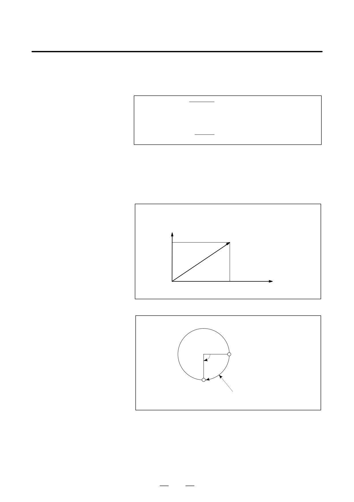
D Linear interpolation
(G91) G01X200.0Y100.0F200.0 ;
Y axis
(End position)
100.0
X axis
0
(Start position)
200.0
D Feedrate for the
rotation axis
G91G01C-90.0 G300.0 ;Feed rate of 300deg/min
(Start point)
90°
(End point)
Feedrate is 300 deg/min
42